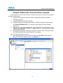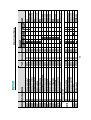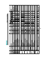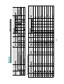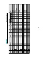
1
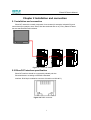
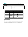
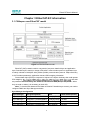
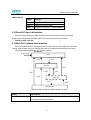
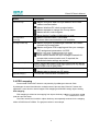
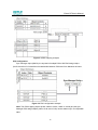
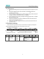
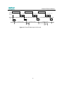
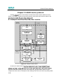
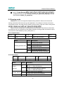
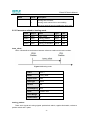
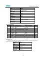
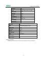
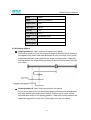
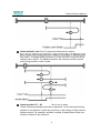
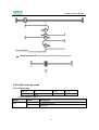
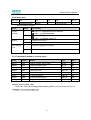
EtherCAT User's Manual
(Version: V1.01)
Version update history
Date
version
description
Author
2012-11-09
V1.00
Initial release.
Gao Lvbo
2012-11-20
V1.01
The section 5.8 Interpolation position
mode is added.
Gao Lvbo
EtherCAT User's Manual
Content
Chapter 1 Brief introduction of EtherCAT ..............................................................1
1.1 What is EtherCAT .......................................................................................... 1
1.2 EtherCAT general introduction .......................................................................1
1.3 Product introduction .......................................................................................1
1.4 CoE terms ......................................................................................................1
1.5 Data type .......................................................................................................2
1.6 Communication specifications ........................................................................3
1.7 EC-100 module structure ...............................................................................4
1.8 LED indicators................................................................................................4
Chapter 2 Installation and connection ....................................................................7
2.1 Installation and connection ............................................................................. 7
2.2 EtherCAT interface specification ....................................................................7
2.3 Wire specification ...........................................................................................8
Chapter 3 EtherCAT-EC information.......................................................................9
3.1 CANopen over EtherCAT model ....................................................................9
3.2 EtherCAT slave information .........................................................................10
3.3 EtherCAT network state machine .................................................................10
3.4 PDO mapping ..............................................................................................11
3.5 Emergency message ...................................................................................13
Chapter 4 Network synchronization based on distributed clocks .....................14
Chapter 5 CiA402 device protocol .........................................................................16
5.1 CANopen over EtherCAT(CoE) state machine............................................. 16
5.2 Parameters for device control ......................................................................17
5.2.1 controlword ...................................................................................................... 18
5.2.2 statusword ....................................................................................................... 19
5.2.3 shutdown_option_code..................................................................................... 21
5.2.4 disable_operation_option_code ........................................................................ 21
5.2.5 quick_stop_option_code ................................................................................... 22
5.2.6 halt_option_code .............................................................................................. 23
5.2.7 fault_reaction_option_code............................................................................... 23
5.3 Control mode ...............................................................................................24
5.4 Control mode parameters ............................................................................24
5.5 Homing mode...............................................................................................26
5.5.1 Control word..................................................................................................... 26
5.5.2 State word ........................................................................................................ 26
5.5.3 Parameters related to homing mode ................................................................. 27
5.5.4 Homing method................................................................................................ 30
5.6 Profile velocity mode ....................................................................................32
i
EtherCAT User's Manual
5.6.1 Control word..................................................................................................... 32
5.6.2 State word ........................................................................................................ 33
5.6.3 Parameters related to velocity mode................................................................. 33
5.7 Profile position mode....................................................................................37
5.7.1 Control word..................................................................................................... 37
5.7.2 State word ........................................................................................................ 38
5.7.3 Parameters related to position control .............................................................. 38
5.7.4 Function description ......................................................................................... 42
5.8 Interpolation position mode ..........................................................................44
5.8.1 Control word..................................................................................................... 44
5.8.2 State word ........................................................................................................ 44
5.8.3 Parameters related to interpolation position control ........................................... 45
5.9 Cyclic synchronous position mode ...............................................................48
Chapter 6 EtherCAT communication example .....................................................49
Appendix: Object dictionary..................................................................................53
ii
EtherCAT User's Manual
Chapter 1 Brief introduction of EtherCAT
1.1 What is EtherCAT
EtherCAT is an open network based on Ethernet to achieve real time control. It could
support high speed and synchronized control. By using efficient network topology, the network
structure with too many concentrator and complicated connections are avoided. It is very suitable
to use this protocol in motion control and other factory automation applications.
1.2 EtherCAT general introduction
EtherCAT technology breaks the limits of normal internet solution. Through this technology,
to receive Ethernet data, decode the data, and then copy the process data to
different devices. EtherCAT
information when the frame passes this device. As the same, some data will be written into the
frame when it passes the device. In this way, data reading and data writing could be done within
several nanoseconds.
EtherCAT uses standard Ethernet technology and support almost kinds of topologies,
including the line type, tree type, star type and so on. Its physical layer could be 100 BASE-TXI
twisted-pair wire, 100BASE-FX fiber or LVDS (low voltage differential signaling). It could also be
done through switch or media converters or in order to achieve the combination of different
Ethernet structure.
Relying on the ASICs for EtherCAT in the slave and DMA technology that reads network
interface data, the processing of the protocol is done in the hardware. EtherCAT system could
update the information for 1000 I/O within 30µs. It could exchange a frame as big as 1486 bytes
within 300µs. This is almost like 12000 digital output or input. Controlling one servo with 100
8-byte I/O data only takes 100µs. Within this period, the system could update the actual positions
and status presented by command value and control data. Distributed clock technology could
make the cyclic synchronous error lower than 1µs.
1.3 Product introduction
ProNet servo drive achieves EtherCAT communication through EC100 network module. It is
a real time Ethernet communication and the application layer applies CANopen Drive Profile (CiA
402).
Besides supporting the PV, PP, IP and other control mode defined in CANopen DS402, this
module also supports CSP control mode. Clients could switch the control mode by changing
correspondent parameters. It is available from simple velocity control to high speed high
precision position control.
1.4 CoE terms
The tables below lists the terms used in CANopen and EtherCAT.
Abbreviation
Description
APRD
Auto Increment Physical Read: a command of EtherCAT Date link layer.
1
EtherCAT User's Manual
Abbreviation
Description
APWR
Auto Increment Physical Write: a command of EtherCAT Date link layer.
APRW
Auto Increment Physical ReadWrite: a command of EtherCAT Date link
layer.
ARMW
Auto Increment Physical Read Multiple Write: a command of EtherCAT
Date link layer.
BRD
Broadcast Read: a command of EtherCAT Date link layer.
BRW
Broadcast Write: a command of EtherCAT Date link layer.
CiA
CAN in Automation
CoE
CANopen over EtherCAT
DC
Distributed Clocks Mechanism to synchronize EtherCAT slaves and master.
ECAT
EtherCAT
EEPROM
Electrically Erasable Programmable Read Only Memory.
ESC
EtherCAT Slave Controller
ESM
EtherCAT State Machine
ETG
EtherCAT Technology Group(http://www.ethercat.org)
EtherCAT
Real-time Standard for Industrial Ethernet Control Automation
Technology(Ethernet for Control Automation Technology)
FMMU
Filedbus Memory Management Unit
INIT
INIT state of EtherCAT state machine
LRD
Logical Read: a command of EtherCAT Date link Layer
LWR
Logical Write: a command of EtherCAT Date link Layer
LRW
Logical ReadWrite: a command of EtherCAT Date link Layer
OP
Operational state of EtherCAT state machine
OD
Object Dictionary
PDO
Process Data Object
PREOP
Pre-Operational state of EtherCAT state machine
RXPDO
Receive PDO, i.e. Process Date that will be received by ESC
SAFEOP
Safe-Operational state of EtherCAT state machine
SDO
Service Data Object
SyncManager
ESC unit for coordinated data exchange between master and slaver
controller
TXPDO
Transmit PDO, i.e. Process Date that will be transmitted by ESC
1.5 Data type
The table below lists all the data types and their range that will be used in this manual.
2
EtherCAT User's Manual
Code
Data type
Range
UINT8
Unsigned integer 8
0 to 255
INT8
Integer 8
-128 to +127
UINT16
Unsigned integer 16
0 to 65535
INT16
Integer 16
-32768 to +32767
UINT32
Unsigned integer 32
0 to 4294967295
INT32
Signed integer 32
STR
string
2147483648 to +2147483627
-
1.6 Communication specifications
applied
IEC 61158 Type12, IEC 61800-7 CiA402 Drive Profile
communication
standard
Physical layer
Interface
Wiring
SyncManager
FMMU
EtherCAT
communication
100BASE-TX (IEEE802.3)
CN5 (RJ45): EtherCAT Signal IN
CN6 (RJ45): EtherCAT Signal OUT
Level-5 twisted pair wire
SM0: output mailbox, SM1: input mailbox
SM2: input process data, SM3: Output
process data
FMMU0: mapped to output area of process
data(RXPDO)
FMMU1: mapped to transmit area of process
data(TxPDO)
FMMU2: mapped to mailbox status
EtherCAT
APRD, FPRD, BRD, LRD, APWR, FPWR, BWR, LWR,
Commands
ARMW, FRMW
(Data Link
Note: APRW, FPRW, BRW, LRW Commands are not
Layer)
supported.
PDO data
Dynamic PDO mapping
Mailbox (CoE)
Emergency Message, SDO Request, SDO Response,
SDO information
Note:
TxPDO/RxPDO.
3
EtherCAT User's Manual
data(DC)
Free-run, DC mode(activated by configuration)
supported DC cycle time: 250us 2ms
SII
256 bytes(read only)
Distributed
LED light
CiA402 Drive Profile
EtherCAT system indicator(SYS)×1
EtherCAT run indicator(RUN)×1
EtherCAT error indicator(ERR)×1
Homing mode
Profile position mode
Profile velocity mode
Cyclic synchronous position mode
1.7 EC-100 module structure
Figure 1-1 Module structure
1.8 LED indicators
SYS
EC-100 module indicates light, used to show the software status in the module.
LED light(green/yellow)
Introduction
Status
Description
Off
Continuously off
No power supply or
reset status
Flashing( yellow)
On (green)
Boot mode
program has finished
Continuously on
initiation and
operates well.
RUN
RUN light is used to indicate the communication status of EtherCAT
4
EtherCAT User's Manual
LED indicator(green)
Introduction
Status
Description
Off
Continuously off
System
initiation
pre-operation
Blinking
status
safety
Double
operation
flashing
On
mode
Operation
Continuously on
status
ERR
ERR light is used to indicate the error in EtherCAT communication.
LED light(red)
Status
Description
Off
Continuously off
Introduction
No error
Blinking
Due to register
problem or
object
configuration
problem, the
status
changing
required by the
be achieved.
Single
Sync error.
flash
Communicatio
n data error
Double
Application
flash
program
supervision
overtime.
SyncManager
watchdog
overtime
5
EtherCAT User's Manual
Flickerin
Initiating error
g
On
Continuously on
PDI
supervision
overtime
LINK/ACT (green light on RJ45 COM1/COM2)
LINK/ACT light is used to indicate the physical communication and if there is data exchange.
LED light(green)
Status
Description
Off
Continuously off
Introduction
Physical level
communication has not
been started. EtherCAT
controller has not been
started.
Flickering
On
slave is exchanging data
Continuously on
There is connection in link
layer but there is no date
exchange
6
EtherCAT User's Manual
Chapter 2 Installation and connection
2.1 Installation and connection
EtherCAT network is normally composed of one master (for example, industrial PC) and
some slaves (for example, servo drives, filed bus terminals and so on). Every EtherCAT slave
has two standard Ethernet interfaces.
Figure 2-1 EtherCAT network
2.2 EtherCAT interface specification
EtherCAT interface should be connected by twisted pair wire
Electrical feature: according to IEEE802.3 standard
Interface: RJ45 8 pin modularize connector (According to ISO 8877)
Figure 2-2 RJ45 connector
7
EtherCAT User's Manual
RJ45 connector
connector
description
CN5
EtherCAT IN port
CN6
EtherCAT OUT port
Pin layout
Pin No.
Signal name
abbreviation
signal transmit direction
1
Data transmit
TD
Output
2
Data transmit
TD-
Output
3
Data receive
RD+
Input
4
Not used
5
6
Not used
Data receive
RD-
Input
7
Not used
8
Not used
Interface grounding
grounding
FG
2.3 Wire specification
Level 5 or above.
Shield
Note: Identify the cable model is suitable for the interface. Identify items are as follows:
conductor specification, single cable/pair cable, two pair/ four pair, external diameter etc.
8
EtherCAT User's Manual
Chapter 3 EtherCAT-EC information
3.1 CANopen over EtherCAT model
Figure 3-1 Communication model
EtherCAT (CoE) network model is composed of two parts: data link layer and application
layer. Data link layer is mainly in charge of EtherCAT communication protocol. Application layer
is mainly oriented to CANOpen drive profiles (DS402) communication protocol. Object dictionary
in CoE includes parameters, application data and PDO mapping information.
Process data object (PDO) is composed of objects in the object dictionary that could operate
PDO mapping
and write
are periodical without checking OD. However, mail communication (SDO) is not periodic. When
they are read or written, it is necessary to check OD.
Note: To decode SDO data and PDO data on EtherCAT data link layer correctly, we need to
configure FMMU and Sync Manager as below
Sync Manager Configuration
Sync Manager
Assignment(Fixed)
Size
Start Address(Fixed)
Sync Manager 0
Assigned to Receive Mailbox
128byte(Fixed)
0x1000
Sync Manager 1
Assigned to Transmit Mailbox
128byte(Fixed)
0x1080
Sync Manager 2
Assigned to Receive PDO
0 to 200byte
0x1100
Sync Manager 3
Assigned to Transmit PDO
0 to 200byte
0x1358
9
EtherCAT User's Manual
FMMU Settings
FMMU
Settings
FMMU 0
Mapped to Receive PDO
FMMU 1
Mapped to Transmit PDO
FMMU 2
Mapped to Fill Status of Transmit Mailbox
3.2 EtherCAT slave information
EtherCAT slave information (XML document) could be read by the master to build the
master-slave configuration. ESTUN ProNet servo drive offers document as below
ESTUN_ProNet_CoE.xml
3.3 EtherCAT network state machine
EtherCAT state machine is used to describe the states that one slave applies and the state
change. State change request is normally launched by the master and answered by the slave.
state machine.
The graph below describes
Power ON
Init
(PI)
(IP)
Pre-Op
(SI)
(PS)
(OI)
(OP)
(SP)
Safe-Op
(SO)
Operational
Status
Description
Init
No mailbox communication
No process data communication
10
(OS)
EtherCAT User's Manual
Status
Init to Pre-Op
Pre-Operation
(Pre-Op)
Pre-Op to Safe-Op
Description
Master configures data link layer address and initiate
mailbox communication
Master initializes DC clock synchronization.
Master requests to change into Pre-op status.
Master sets AL control register.
Slave checks if mailbox initialization is good.
Mailbox communication is activated.
Process data communication is not available.
Master configures SyncManager channels and FMMU
channels for process data.
Master configures PDO mapping and the sync manager
PDO assignment parameters via SDO.
Slave checks whether the sync manager channels for
process data communication and, if required, the
distributed clocks settings are correct.
Safe-Operation(Safe-Op)
output. Output is set as safety status.
Safe-Op to Op
Operational(Op)
Master transmits effective output data.
Master asks to change into OP status.
Process data communication is available now.
3.4 PDO mapping
Process data of EtherCAT slaves is composed by SyncMangaer channels. Each
SyncMangaer channel describes the consistent area of process data. EtherCAT slaves with
application control function should support PDO mapping and SM-PDO-Assign object reading.
PDO mapping
PDO mapping is related to the mapping from object dictionary to
s
(real time process data).
The index 0x1600 and 0x1A00 in object dictionary are separately reserved for the mapping
tables of RXPDO and TxPDOs. The graph as below is one example.
11
EtherCAT User's Manual
Figure 3-2 PDO mapping example
PDO configuration
Sync manager object (SMCO) is composed of multiple PDOs. SM-PDO-Assign object
(0x1C12 and 0x1C13) describes the relationship between PDOs and Sync Manager as below
Figure 3-3 PDO configuration example
Note: The PDO mapping objects (index 1600h to 1603h, 1A00h to 1A03h) and the Sync
Manager PDO assign objects (Index 1C12h and 1C13h) can be written only in Pre-Operation
state.
12
EtherCAT User's Manual
PDO mapping process
1
2
3
4
5
6
Stop PDO allocating function (set the sub-index 0 of 0x1c12 and 0x1c13 into
0).
Stop PDO mapping function (set sub-index 0 of 0x1600 0x1603 and
0x1A00 0x1A03 into 0).
Set the number of mapping entries in PDO mapping objects (Set sub-index 0
of object 0x1600h to 0x1603h/0x1A00h to 0x1A03h).
Set the assignment of the Sync manager and PDO (Set sub index 1 of object
0x1C12h and 0x1C13h)
Enable the assignment of the Sync manager and PDO (Set sub index 0 of
object 0x1C12h and 0x1C13h to 1).
Over again open PDO assignment function (set the sub-index 0 of 0x1c12
and 0x1c13 into 1)
3.5 Emergency message
When the servo drive generates an alarm, Coe will activate an emergency message and
inform consumers the current servo drive model number and error code.
Emergency message structure:
6 bytes
2 bytes
2 bytes
1 byte
5 bytes
Mailbox Header
CoE Header
ErrorCode
Error Register
Data
Standard CANopen urgent event message
Standard data frame head
Byte
0
Data
1
Data1
2
3
4
Emergency
Error
Reserved
Manufacturer Specific Error Field
Error Code
Register
ProNet
(Object
Alarm/Warning
1001h)
Code*2
13
5
Optional
6
Reserved
7
EtherCAT User's Manual
Chapter 4 Network synchronization based on
distributed clocks
Any slave in the EtherCAT network can be used as reference clock for the whole network. It
provides system time. And the distribute clock in slave device synchronizes with the reference
clock. It enables
local application to synchronize with reference clock events.
EC-netX50 model achieves the synchronous mode as following. Switching synchronous
mode can be controlled by synchronous control register (ESC 0x980 and 0x981).
Free-Run mode (ESC register: 0x980 = 0x0000)
In this mode, local application cycle, communication cycle and master cycle is
independent.
DC mode (ESC register: 0x980 = 0x0300))
In this mode, local application is synchronous with Sync0.
Index
Sub
Name
PDO
Access
Mapping
Type
Value
Sync Manager channel 2 (process data output) Synchronization
Current status of DC
mode
1
Synchronization
type
RO
No
UINT
0x1C32
0: Free-run
2: DC Mode
(Synchronous
with Sync0)
Sync0 event cycle
[ns]
(The value is set by
2
Cycle time
RO
No
UINT
master via ESC
register.)
range: 125000*n (n
= 2 16) [ns]
Sync Manager channel 3 (process data input) Synchronization
0x1C33
3
6
Shift time
Calc and copy
time
RO
No
UINT
RO
No
UINT
Time schedule figure in DC mode is as follows:
14
EtherCAT User's Manual
Master application task
Master application task
Master application task
Master
Network
Frame
U
Frame
U
Frame
Calc + Copy time
(1C33:06)
Slave
Sync0
Event
U
U
U
U
Sync0
Event
Sync0
Event
Cycle time (1C32:02)
Cycle time (1C32:02)
Delay Time
(1C32:09)
Cycle time (1C32:02)
Shift time (1C32:03)
Delay Time
(1C32:09)
Input
latch
output
valid
Figure 4-1 Time schedule figure in DC mode
15
U
EtherCAT User's Manual
Chapter 5 CiA402 device protocol
ProNet
control is used mainly to achieve the motion control in different control
modes. The master controls the servo drive through control word and knows the status of the
5.1 CANopen over EtherCAT(CoE) state machine
Power
Disabled
Fault
Start
0
13
Not Ready to
Switch On
Fault
Reaction
Active
1
2
Fault
7
12
Ready to
Switch On
Power
Enabled
3
9
8
14
15
Switch On
Disabled
10
6
Switched
On
4
5
11
16
Operation
Enable
Quick Stop
Active
Figure 5-1 CANopen state machine
As above, the state machines
es
servo drive will finish initiating and then enter SWITECH_ON_DISA status. Now we could
configure the servo drive, for example, set the working mode of the servo drive as profile position
mode.
16
EtherCAT User's Manual
At this time, the main power supply is still shut down and the servo motor is now excitated.
After the state transition 2, 3 and 4, the servo drive will be in OPERATION ENABLE mode. At this
time, the main power will be switched on and servo drive starts to control the servo motor
according to the configured working mode. So, before this state, we must ensure the servo
parameters are correct. State Transition 9 will be used to shut down the main power
States
Description
Not Ready to Switch On
Servo drive is initiating.
Switch On Disabled
Initiation completed.
Ready to Switch On
Switched On
Servo drive enters Switch On state. The servo motor is not
servo-on yet.
Servo drive ready and main power is on
Operation Enable
Quick Stop Active
Fault Reaction Active
Fault
Servo on and control the servo motor according to the control
mode.
Servo drive stops in pre-defined method
Servo drive detects alarm and stop according to pre-defined
method. Servo motor is still on.
Servo off
5.2 Parameters for device control
Index
Object
Name
Type
Attr.
6040 h
VAR
Controlword
UINT16
RW
6041 h
VAR
Statusword
UINT16
RO
605A h
VAR
Quick stop option code
INT16
RW
605B h
VAR
Shutdown option code
INT16
RW
605C h
VAR
Disabled operation option code
INT16
RW
605D h
VAR
Halt option code
INT16
RW
605E h
VAR
Fault reaction option code
INT16
RW
17
EtherCAT User's Manual
5.2.1 controlword
Index
6040 h
Name
Control word
Object Code
VAR
Data Type
UINT16
Access
RW
PDO Mapping
YES
Units
--
Value Range
--
Default Value
0
Control word bit description:
Bit0 ~ 3 and Bit7:
The transmission of state machine will be triggered by the command
composed by these 5 bits.
Device control command list
Command
Bit of the controlword
Fault
Enable
Quick
Enable
Switch
Transitions
reset
operation
stop
voltage
on
Shutdown
0
×
1
1
0
2,6,8
Switch on
0
0
1
1
1
3*
Switch on
0
1
1
1
1
3**
Disable
0
×
×
0
×
7,9,10,12
Quick stop
0
×
0
1
×
7,9,10,11
Disable
0
0
1
1
1
5
0
1
1
1
1
4,16
×
×
×
×
15
voltage
operation
Enable
operation
Fault reset
Note: X means this bit could be ignored.
18
EtherCAT User's Manual
Bit4, 5, 6, 8:
In d
Control mode
Bit
profile position mode
profile velocity mode
homing mode
4
New set point
reserved
Start homing operation
5
Change set immediately
reserved
reserved
6
abs/rel
reserved
reserved
8
Halt
Halt
Halt
The other bits: All reserved.
5.2.2 statusword
Index
6041 h
Name
statusword
Object Code
VAR
Data Type
UINT16
Access
RO
PDO Mapping
YES
Units
--
Value Range
--
Default Value
--
Statusword bit introduction is as below
bit
introduction
0
Ready to switch on
1
Switched on
2
Operation enabled
3
Fault
4
Voltage enabled
5
Quick stop
6
Switch on disabled
7
Warning
9~8
reserved
10
Target reached
19
EtherCAT User's Manual
bit
introduction
11
Internal limit active
13~12
Operation mode specific
15~14
reserved
Bit0 ~ 3 , Bit5 and Bit6:
The combination of these bits represents the status of the servo drive
Value(binary)
State
xxxx xxxx x0xx 0000
Not ready to switch on
xxxx xxxx x1xx 0000
Switch on disabled
xxxx xxxx x01x 0001
Ready to switch on
xxxx xxxx x01x 0011
Switched on
xxxx xxxx x01x 0111
Operation enabled
xxxx xxxx x00x 0111
Quick stop active
xxxx xxxx x0xx 1111
Fault reaction active
xxxx xxxx x0xx 1000
Fault
Bit4: Voltage enabled
When this bit is 1, it means the main power is on.
Bit5: Quick stop
When this bit is 0, it means the servo drive will stop the servo motor
according to the configuration(605A h: quick_stop_option_code)
Bit7: Warning
When the bit is 1, it means the servo drive detects alarm.
Bit10: Target reached
In different control mode, this bit has different meanings.
- In Profile Position Mode, when the set position is reached, this bit will
be set as 1. When Halt is activated and speed decreases to zero, this bit
will be set as 1. When a new position is set, this bit will be cleared.
- In Profile Velocity Mode, when the speed reaches the required speed,
this bit will be set as 1. When Halt is activated, the speed will decrease to
zero and this bit will be set as 1.
Bit11: Internal limit active
When this bit is 1, it means that the internal torque has surpassed the set
value.
Bit12, 13:
These two bits in different control mode have different meaning.
20
EtherCAT User's Manual
Control mode
Bit
profile position mode
profile velocity mode
homing mode
12
Set-point acknowledge
Speed
Homing attained
13
Following error
Max slippage error
Homing error
The other bits: All reserved
5.2.3 shutdown_option_code
When Operation Enable mode is transit to Ready to Switch On status,
Shutdown_option_code will be used to define how to stop the servo motor.
Index
605B h
Name
Shutdown option code
Object Code
VAR
Data Type
INT16
Access
RW
PDO Mapping
NO
Units
--
Value Range
0,1
Default Value
0
value
Introduction
0
Shutdown servo excitation signal. Servo motor will stop freely.
1
After the servo motor decelerates and stops, the servo excitation signal will be shut
down.
5.2.4 disable_operation_option_code
When the status of Operation Enable transits to Switched On status,
disable_operation_option_code will decide how to halt.
21
EtherCAT User's Manual
Index
605C h
Name
Disable operation option code
Object Code
VAR
Data Type
INT16
Access
RW
PDO Mapping
NO
Units
--
Value Range
0,1
Default Value
0
Value
Introduction
0
Shutdown servo excitation signal. Servo motor will stop freely.
After the servo motor decelerates and stops, the servo excitation signal will be shut
1
down.
5.2.5 quick_stop_option_code
When the Operation Enable status transits to Quick Reaction Active status,
quick_stop_option_code will define how to stop.
Index
605A h
Name
quick_stop_option_code
Object Code
VAR
Data Type
INT16
Access
RW
PDO Mapping
NO
Units
--
Value Range
0,1,2,5,6
Default Value
0
Value
Introduction
0
Shutdown servo excitation signal. Servo motor will stop freely.
1
After the servo motor decelerates and stops, the servo excitation signal will be shut
down.
22
EtherCAT User's Manual
Value
Introduction
2
After servo motor stops urgently, the servo excitation signal will be shut down.
5
After the servo motor decelerates to zero, it will still stay in QuickStop status.
6
After the servo motor stops urgently, it will still stay in QuickStop status.
5.2.6 halt_option_code
When bit8 of Controlword is 1, halt option code will define how to halt. .
Index
605D h
Name
halt_option_code
Object Code
VAR
Data Type
INT16
Access
RW
PDO Mapping
NO
Units
--
Value Range
1,2
Default Value
0
Value
Introduction
1
Servo motor will decelerate gradually to zero
2
Servo motor will decelerate urgently and then stop.
5.2.7 fault_reaction_option_code
When it alarms, fault_reaction_option_code will decide how to halt. .
23
EtherCAT User's Manual
Index
605D h
Name
fault_reaction_option_code
Object Code
VAR
Data Type
INT16
Access
RW
PDO Mapping
NO
Units
--
Value Range
0
Default Value
0
Value
Introduction
The servo excitation signal will be shut down and servo motor will
0
stop freely.
5.3 Control mode
Now, ProNet servo drive supports 5 control modes:
HOMING MODE
PROFILE VELOCITY MODE
PROFILE POSITION MODE
CYCLIC SYNCHRONIZATION POSITION MODE
INTERPOLATION POSITION MODE
This chapter will mainly describe these 5 control methods as above.
5.4 Control mode parameters
Index
Object
Name
Type
Attr.
6060 h
VAR
modes_of_operation
INT8
RW
6061 h
VAR
modes_of_operation_display
INT8
RO
modes_of_operation
24
EtherCAT User's Manual
Index
6060 h
Name
modes_of_operation
Object Code
VAR
Data Type
INT8
Access
RW
PDO Mapping
YES
Units
--
Value Range
1,3,6
Default Value
0
Value
Introduction
0
Not any control mode
1
PROFILE POSITION MODE
3
PROFILE VELOCITY MODE
6
HOMING MODE
8
CYCLIC SYNCHRONIZATION POSITION
modes_of_operation_display
nt control mode could be read from the modes_of_operation_display.
Index
6061 h
Name
modes_of_operation_display
Object Code
VAR
Data Type
INT8
Access
RO
PDO Mapping
YES
Units
--
Value Range
1,3,6,7,8
Default Value
0
Note:
Only through the parameters of modes_of_operation_display, we could get
the control mode of the servo drive.
25
EtherCAT User's Manual
Only in Target Reached
configured control mode. And then modes_of_operation_display could be
the same as modes_of_operation.
5.5 Homing mode
PRONET servo drive now supports multiple homing methods. Clients could choose the
homing method that suits the motor type and application. For example, if the servo drive uses
incremental encoder, we could choose C pulse to do the homing. If the servo drive is using serial
Clients can set homing method, homing speed and acceleration. After the servo drive finds
the reference point, we could also set the distance between homing position and reference point
as much as the value defined by home_offset (607C h).
5.5.1 Control word
15 ~ 9
8
7~5
4
3~0
*
Halt
*
home_start_operation
*
*: please referred to previous chapters
Name
Homing operation start
Value
Description
0
Homing mode inactive
Start homing mode
1
Homing mode active
Interrupt homing mode
Halt
0
Execute the instruction of bit 4
1
Stop axle with homing acceleration
5.5.2 State word
15 ~ 14
13
12
11
10
9~0
*
homing_error
homing_attained
*
target_reached
*
*: Please refer to the previous chapters
Name
Target
reached
Homing attained
Homing error
Value
0
1
Description
Halt = 0: Home position not reached
Halt = 1: Axle decelerates
Halt = 0: Home position reached
Halt = 1: Axle has velocity 0
0
Homing mode not yet completed
1
Homing mode carried out successfully
0
No homing error
26
EtherCAT User's Manual
Name
Value
Description
Homing error occurred;
1
Homing mode carried out not successfully;
The error cause is found by reading the error code
5.5.3 Parameters related to homing mode
Index
Object
Name
Type
Attr.
607C h
VAR
home_offset
INT32
RW
6098 h
VAR
homing_method
INT8
RW
6099 h
ARRAY
homing_speeds
UINT32
RW
609A h
VAR
homing_acceleration
INT32
RW
home_offset
Home_offset defines the distance between reference position and homing position.
Figure 5-2 Homing mode
Index
607C h
Name
home_offset
Object Code
VAR
Data Type
INT32
Access
RW
PDO Mapping
YES
Units
position units
Value Range
--
Default Value
0
homing_method
There are 4 signals as homing signals: positive limit switch, negative limit switch, reference
position switch and C pulse.
27
EtherCAT User's Manual
Index
6098 h
Name
homing_method
Object Code
VAR
Data Type
INT8
Access
RW
PDO Mapping
YES
Units
--
Value Range
1,2,3,4,17,18,19,20
Default Value
1
Homing method table
Method
Direction
Target position
Reference Position
DS402
1
negative
NOT
C pulse
1
2
positive
POT
C pulse
2
3
negative
reference position switch
C pulse
3
4
positive
Reference position switch
C pulse
4
17
negative
NOT
NOT
17
18
positive
POT
POT
18
19
negative
reference position switch
reference position switch
19
20
positive
reference position switch
reference position switch
20
35
--
currently position
currently position
35
homing_speeds
Two kinds of speed are used in finding the reference position: The speed to find reference
position and the speed to find zero position.
Index
6099 h
Name
homing_speeds
Object Code
ARRAY
No. of Elements
2
Data Type
INT32
28
EtherCAT User's Manual
Sub-Index
01 h
Name
speed_during_search_for_switch
Object Code
VAR
Data Type
INT32
Access
RW
PDO Mapping
YES
Units
speed units
Value Range
--
Default Value
0
Sub-Index
02 h
Name
speed_during_search_for_zero
Object Code
VAR
Data Type
INT32
Access
RW
PDO Mapping
YES
Units
speed units
Value Range
--
Default Value
0
homing_acceleration
Acceleration and deceleration in homing are all defined by homing_acceleration.
29
EtherCAT User's Manual
Index
609A h
Name
homing_acceleration
Object Code
VAR
Data Type
INT32
Access
RW
PDO Mapping
YES
Units
acceleration units
Value Range
--
Default Value
0
5.5.4 Homing method
Homing method 1: Use C pulse and negative limit switch
Servo drive needs to move at first toward negative direction fast till reaching
the negative limit switch and then decelerate till stop. And then, servo motor
will be bounced back slowly and find the target homing position. Under this
homing method, the target homing position is the first C pulse away from the
limit switch.
Homing method 2: Use C pulse and positive limit switch
At first servo motor will move fast toward positive direction and decelerate to
stop after reaching the positive limit switch. And then servo motor will be
bounced back slowly to find homing position. Under this homing method, the
target homing position is the first C pulse away from the limit switch.
30
EtherCAT User's Manual
Home method 3 and 4: Use C pulse and reference limit switch
limit switch. The target homing position is on the left side or right side of the
reference limit switch. The distance between the reference position switch
and homing position is one C pulse.
Homing method 17 ~ 20
Not to use C pulse
These 4 homing methods are similar to approach 1-4 but the target homing
position is not relied on C pulse any more but on the change of limit switch or
reference point. For example, as below, method 19 and method 20 are just
similar to method 3 and method 4.
31
EtherCAT User's Manual
Homing method 35: set current position as the homing point.
5.6 Profile velocity mode
5.6.1 Control word
15 ~ 9
8
7~4
3~0
*
Halt
*
*
*: Refer to previous chapters
Name
Value
Description
Halt
0
Execute the motion
1
Stop axle
32
EtherCAT User's Manual
5.6.2 State word
15 ~ 14
13
12
11
10
9~0
*
MaxSlippageError
Speed
*
Target reached
*
*: Refer to previous chapters
Name
Value
Target
0
Description
Halt = 0: Target position not reached
Halt = 1: Axle decelerates
Halt = 0: Target velocity reached
Halt = 1: Axle has velocity 0
reached
1
Speed
Max slippage
0
Speed is not equal 0
1
Speed is equal 0
0
Maximum slippage not reached
1
Maximum slippage reached
error
5.6.3 Parameters related to velocity mode
Index
Object
Name
Type
Attr.
6069 h
VAR
velocity_sensor_actual_value
INT32
RO
606B h
VAR
velocity_demand_value
INT32
RO
606C h
VAR
velocity_actual_value
INT32
RO
609D h
VAR
velocity_window
UINT16
RW
606E h
VAR
velocity_window_time
UINT16
RW
606F h
VAR
velocity_threshold
UINT16
RW
6070 h
VAR
velocity_threshold_time
UINT16
RW
60FF h
VAR
target_velocity
INT32
RW
velocity_sensor_actual_value
The master could read velocity_sensor_actual_value to know the current velocity. The
par
33
EtherCAT User's Manual
Index
6069 h
Name
velocity_sensor_actual_value
Object Code
VAR
Data Type
INT32
Access
RW
PDO Mapping
YES
Units
0.1rmps
Value Range
--
Default Value
--
(1R/10min)
velocity_demand_value
Master can read velocity_demand_value to know the current reference speed value of the
Index
606B h
Name
velocity_demand_value
Object Code
VAR
Data Type
INT32
Access
RO
PDO Mapping
YES
Units
speed units
Value Range
--
Default Value
--
velocity_actual_value
The master can read velocity_ actual _value to know the current velocity of the servo motor.
34
EtherCAT User's Manual
Index
606C h
Name
velocity_actual_value
Object Code
VAR
Data Type
INT32
Access
RO
PDO Mapping
YES
Units
speed units
Value Range
--
Default Value
--
velocity_window
The difference between velocity_actual_value (606C h) and target_velocity (60FF h) is
defined as actual velocity error window. If the actual velocity error window is always smaller than
velocity_window(606D h) within the time set by velocity_window_time(606E h ), then bit 10 of
status word (target_reached) will be set as 1 to indicate that the set velocity has been reached.
Index
Name
Object Code
Data Type
Access
PDO Mapping
Units
Value Range
Default Value
606D h
velocity_window
VAR
UINT16
RW
YES
speed units
-20 R/10min
velocity_window_time
Velocity window comparator is composed of velocity_window_time and velocity_window.
35
EtherCAT User's Manual
Index
606E h
Name
velocity_window_time
Object Code
VAR
Data Type
UINT16
Access
RW
PDO Mapping
YES
Units
ms
Value Range
--
Default Value
0
velocity_threshold
Velocity_threshold indicates a range close to zero speed in order to define if the servo
motor has already stopped.
Index
606F h
Name
velocity_threshold
Object Code
VAR
Data Type
UINT16
Access
RW
PDO Mapping
YES
Units
speed units
Value Range
--
Default Value
10 R/10min
velocity_threshold_time
Velocity_threshold_time is used to set the shortest
under velocity threshold. The unit is: ms
the threshold is more than velocity_threshold_time, status word bit 12(speed is zero) will be set
as 1.
36
EtherCAT User's Manual
Index
6070 h
Name
velocity_threshold_time
Object Code
VAR
Data Type
UINT16
Access
RW
PDO Mapping
YES
Units
ms
Value Range
--
Default Value
0
target_velocity
Target_velocity is reference speed.
Index
60FF h
Name
target_velocity
Object Code
VAR
Data Type
INT32
Access
RW
PDO Mapping
YES
Units
speed units
Value Range
--
Default Value
0
5.7 Profile position mode
5.7.1 Control word
15 ~ 9
8
7
6
5
4
3~0
*
Halt
*
abs / rel
change set immediately
New set-point
*
*: Please refer to previous chapters
Name
Value
Description
New Set-point
0
Does not assume target position
1
Assume target position
37
EtherCAT User's Manual
0
Change set
Finish the actual positioning and then start the next
positioning
immediately
Abs/rel
Halt
1
Interrupt the actual positioning and start the next positioning
0
Target position is an absolute value
1
Target position is a relative value
0
Execute positioning
1
Stop axle with profile deceleration (if not supported with
profile acceleration)
5.7.2 State word
15 ~ 14
13
12
11
10
9~0
*
Following error
Set_point acknowledge
*
Target reached
*
*: please refer to previous chapters
N-ame
Value
Description
Halt = 0: Target position not reached
Halt = 1: Axle decelerates
Halt = 0: Target position reached
Halt = 1: Velocity of axle is 0
0
Target reached
1
Set-point
0
acknowledge
Following error
Trajectory generator has not assumed the positioning values
(yet)
1
Trajectory generator has assumed the positioning values
0
No following error
1
Following error
5.7.3 Parameters related to position control
Index
Name
Type
Attr.
PDO Mapping
M/O
6040h
Control word
UINT16
RW
YES
M
6041h
Statusword
UINT16
RO
YES
M
607A h
target_position
INT32
RW
YES
M
607Bh
Positin_range_limit
INT32
RW
NO
O
6081 h
profile_velocity
UINT32
RW
YES
M
6082 h
end_velocity
UINT32
RW
YES
O
6083 h
profile_acceleration
UINT32
RW
YES
O
6084 h
profile_deceleration
UINT32
RW
YES
O
6085 h
quick_stop_deceleration
UINT32
RW
YES
O
6086 h
motion_profile_type
INT16
RW
YES
M
38
EtherCAT User's Manual
target_position
Target_position is reference position and this position could be an incremental value or an
absolute value. It is up to bit6 of control word.
Index
607A h
Name
target_ position
Object Code
VAR
Data Type
INT32
Access
RW
PDO Mapping
YES
Units
position units
Value Range
--
Default Value
0
profile_velocity
Profile_velocity is the speed that the servo motor could finally reach after acceleration.
Index
6081 h
Name
profile_velocity
Object Code
VAR
Data Type
UINT32
Access
RW
PDO Mapping
YES
Units
speed units
Value Range
--
Default Value
0
end_velocity
End_velocity is the speed when servo motor reaches the target_position. Normally we set
this value as 0 in order to stop the servo motor when the servo motor reaches the requested
position. But in continuous multiple position, this value could be set as a non-zero value.
39
EtherCAT User's Manual
Index
6082 h
Name
end_velocity
Object Code
VAR
Data Type
UINT32
Access
RW
PDO Mapping
YES
Units
speed units
Value Range
--
Default Value
0
profile_acceleration
Profile_acceleration is the acceleration speed before reaching the target position.
Index
6083 h
Name
profile_acceleration
Object Code
VAR
Data Type
UINT32
Access
RW
PDO Mapping
YES
Units
acceleration units
Value Range
--
Default Value
100000 R/10min/s
profile_deceleration
Profile_deceleration is the deceleration speed before reaching the target position.
40
EtherCAT User's Manual
Index
6084 h
Name
profile_deceleration
Object Code
VAR
Data Type
UINT32
Access
RW
PDO Mapping
YES
Units
acceleration units
Value Range
--
Default Value
100000 R/10min/s
quick_stop_deceleration
Quick_stop_deceleration is the deceleration speed in Quick Stop.
Index
6085 h
Name
quick_stop_deceleration
Object Code
VAR
Data Type
UINT32
Access
RW
PDO Mapping
YES
Units
acceleration units
Value Range
--
Default Value
200000 R/10min/s
motion_profile_type
Motion_profile_type is used to select the motion curve. Now we only support trapezoid
speed curve.
41
EtherCAT User's Manual
Index
6086 h
Name
motion_profile_type
Object Code
VAR
Data Type
INT16
Access
RW
PDO Mapping
YES
Units
--
Value Range
0
Default Value
0
5.7.4 Function description
There are two methods to allocate a reference position.
Single step setting:
After reaching the target position, servo drive will inform the master that Reach the target
position. And the servo drive will start new motion after getting new target position. Before
getting the new reference position, the velocity of the servo motor is zero.
Continuous setting:
After reaching the target position, the servo motor will keep moving toward next target
position which is set in advance. In this way, the servo motor could move continuously without
pause. Between two reference positions
Above two methods could be switched to each other by using control word bit 4, bit 5 and
statues word bit 12 (set_point_acknowledge) in real time. Through handshaking mechanism,
we could pause the position control in the process and use these bits above to reset the target
position and then re-active and operate.
Single step setting procedure:
1
2
3
At first, set the NMT status into Operational and set the control mode
parameter (6060 h) as 1.
According to the actual demand, we could set the target position
(target_positon: 607A h) and so on.
We need set bit4 (new_set_point) of the control word as 1, bit 5
(change_set_immediately) as 0, bit 6 (absolute/comparative) should be
determined by whether the reference target position is an absolute value or
a comparative value.
42
EtherCAT User's Manual
4
5
We use bit12 (set_point_acknowledge) of the status word to configure the
servo drive acknowledge mechanism. And then we start to operate position
control.
After reaching the target position, servo drive will need to respond through
bit 10 (target_reached) of the status word. And then servo drive will follow
the program to keep moving or accept new target position.
Continuous step setting procedure:
1
2
3
4
5
6
At first, we need to set NMT status into operational and set control mode
(6060 h) as 1. According to actual demand, we need to set the first target
position (target_position: 607A h), target speed, acceleration/deceleration
and other relevant parameters.
Set bit 4 (new_set_point) of control word as 1. Set bit 5
(change_set_immediately) as 0. Set bit6 (absolute/comparative) according
to the type of object position.
Set bit 12 (set_point_acknowledge) of the status word and then start to
operate position control.
Set the second target position (target_position: 607A h), target speed,
acceleration/deceleration speed.
Set bit4 (new_set_point) as 1, bit 5 (change_set_immediately) as 0. Set
Bit6 (absolute/comparative) according to the target position type.
After reaching the first target position, the servo drive will not stop and keep
moving toward the second target position. After reaching the second target
position, the servo drive will respond through status word bit 10
(target_reached). And then the servo motor will follow the program to keep
moving or accept new target position.
43
EtherCAT User's Manual
5.8 Interpolation position mode
5.8.1 Control word
15 ~ 9
8
7
6
5
4
3~0
*
Halt
*
*
*
Enable ip mode
*
*: please referred to previous chapters
Name
Enable ip mode
Halt
Value
Description
0
Interpolated position mode inactive
1
Interpolated position mode active
0
Execute the instruction of bit 4
1
Stop axle
5.8.2 State word
15 ~ 14
13
12
11
10
9~0
*
*
ip mode active
*
Target reached
*
*: please referred to previous chapters
Name
Value
Target
0
reached
1
Description
Halt = 0: Target position not (yet) reached
Halt = 1: Axle decelerates
Halt = 0: Target position reached
Halt = 1: Velocity of axle is 0
ip mode
0
Interpolated position mode inactive
active
1
Interpolated position mode active
44
EtherCAT User's Manual
5.8.3 Parameters related to interpolation position control
Index
Object
Name
Type
Attr.
60C0 h
VAR
Interpolation sub mode select
INT16
RW
60C1 h
ARRAY
Interpolation data record
INT32
RW
60C2 h
RECORD
Interpolation time period
RW
Interpolation sub mode select
Interpolation sub mode select is used to select the method of interpolation under IP control.
Pronet servo drive only offers linear interpolation.
Index
60C0h
Name
Interpolation sub mode select
Object Code
VAR
Data Type
INT16
Access
RW
PDO Mapping
NO
Value Range
0
Default Value
0
Comment
0: Linear interpolation
Interpolation data record
interpolation command only uses the first data whose subindex is 1.
Index
60C1h
Subindex
0
Object Code
ARRAY
Data Type
INT32
Access
RO
PDO Mapping
YES
Value Range
INT8
Default Value
2
Comment
number of entries
45
EtherCAT User's Manual
Index
60C1h
Subindex
1
Object Code
ARRAY
Data Type
INT32
Access
RW
PDO Mapping
YES
Value Range
INT32
Default Value
0
Comment
the first parameter of ip function
Index
60C1h
Subindex
2
Object Code
ARRAY
Data Type
INT32
Access
RW
PDO Mapping
YES
Value Range
INT32
Default Value
0
Comment
The second parameter of ip function
Interpolation time period
Interpolation time period is used to reserve the time data of interpolation position.
46
EtherCAT User's Manual
Index
60C2h
Subindex
0
Object Code
RECORD
Data Type
INT8
Access
RO
PDO Mapping
NO
Value Range
2
Default Value
2
Comment
number of entries
Index
60C2h
Subindex
1
Object Code
Data Type
UINT8
Access
RW
PDO Mapping
YES
Value Range
0~255
Default Value
1
Comment
Interpolation time units
Index
60C2h
Subindex
2
Object Code
Data Type
INT8
Access
RW
PDO Mapping
YES
Value Range
-4~0
Default Value
-3
Comment
Interpolation time index
47
EtherCAT User's Manual
5.9 Cyclic synchronous position mode
Cyclic synchronous position mode is similar to position interpolation mode. In this control
mode, the master could offer extra speed and torque to achieve speed and torque feed forward
control. The interpolation cycle time defines the time for target position updating. In this case,
interpolation cycle time is the same as sync time.
Parameters related to CYCLIC SYNCHRONOUS POSITION MODE
Index
Name
Type
Attr.
PDO Mapping
M/O
6040h
Controlword
UINT16
RW
YES
M
6041h
Statusword
UINT16
RO
YES
M
6064h
Position_actual_value
INT32
RO
YES
M
607A h
target_position
INT32
RW
YES
M
607Bh
Positin_range_limit
INT32
RW
NO
O
6081 h
profile_velocity
UINT32
RW
YES
M
6082 h
end_velocity
UINT32
RW
YES
O
6083 h
profile_acceleration
UINT32
RW
YES
O
6084 h
profile_deceleration
UINT32
RW
YES
O
6085 h
quick_stop_deceleration
UINT32
RW
YES
O
48
EtherCAT User's Manual
Chapter 6 EtherCAT communication example
In this example, we use Beckhoff TwinCAT software as the real time master. Please prepare
as below before the test:
1
2
3
4
5
1) Identify the network interface model number and install the network
interface correctly.
2) Install Beckhoff TwinCAT software.
3) Copy the device description document (.XML document) to the directory
C:\TwinCAT\IO\EtherCAT. (You could contact Estun to have this XML
document)
4)
Pn704 is the address.
After finishing copying, reactivate TwinCAT software. Then TwinCAT will list
an ESTUN ProNet servo drive EtherCAT bus option.
And then please follow steps as below:
1
Use the right button of the mouse to single click I/O Device and choose
EtherCAT network adapter. Name it as Device 1.
49
EtherCAT User's Manual
2
Use the right button of the mouse to single click Device 1 and add a slave
ProNet device.
3
3. Add one NC task and name it as Task 1.
4
Add Axis 1 under NC task.
50
EtherCAT User's Manual
5
Choose application layer protocol CoE.
6
Click Link to button and map servo drive axis to the device.
51
EtherCAT User's Manual
7
Click activate configuration button on the toolbar and activate
configuration. Click online label and start to operate on servo axis.
52