1
REFERENCE MANUAL
Inspector PI50
Vision Sensor
WARNING
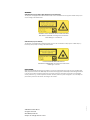
VSPP-5F2113 (Inspector PI50), VSPP-5F2134 (Inspector PI50 ECAT)
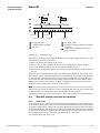
The Inspector is equipped with a LED illumination that must be considered as a lamp system of Risk Group 1 (low
risk) according to IEC 62471:2006
WARNING: OPTICAL RADIATION DO NOT STARE INTO BEAM
RISK GROUP 1 (LOW RISK) according to IEC 62471:2006
Visible LED light λ = 400-800 nm
VSPP-5F2413 (Inspector PI50-IR)
The Inspector is equipped with an LED illumination that must be considered as a lamp system of Risk Group 0 /
Free Group (exempt risk) according to IEC 62471:2006
NOTICE: IR EMITTED FROM THIS PRODUCT
RISK GROUP 0 (EXEMPT RISK) according to IEC 62471:2006
IR LED light λ = 850 nm
DISCLAIMER
©SICK AG 2012-08-23
All rights reserved
8014694/2012-08
Subject to change without notice
0.1.0.166
SICK uses standard IP technology for its products, e.g. IO Link, industrial PCs. The focus here is on providing availability of products and services. SICK always assumes that the integrity and confidentiality of data and rights involved
in the use of the above-mentioned products are ensured by customers themselves. In all cases, the appropriate
security measures, e.g. network separation, firewalls, antivirus protection, patch management, etc., are always implemented by customers themselves, according to the situation.
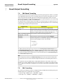
Reference Manual
Inspector PI-series
Inspector PI50
Table of Contents
1. Introduction ....................................................................................................... 7
1. Introduction ............................................................................................... 8
1.1. Interfaces Overview ......................................................................... 8
1.2. Intended Readers ............................................................................ 8
2. Interfaces .......................................................................................................... 9
2. I/O Extension Box ..................................................................................... 10
2.1. Physical Network Connection ........................................................... 10
2.2. Configuration of the IP Address on the I/O Extension Box .................... 10
2.2.1. Basic Configuration of the IP address .................................... 11
2.3. Setup of the I/O Extension Box in the SOPAS Single Device Application .................................................................................................... 11
2.3.1. Enabling the I/O Extension Box ............................................. 12
2.4. Input and Output Connections ......................................................... 12
2.4.1. Special Conditions During Startup ......................................... 13
2.4.2. Connection to the I/O Extension Box lost During Operation ....... 13
2.4.3. Object Selection with I/O Extension Box ................................. 13
2.4.4. Timing Issues ..................................................................... 13
2.4.5. Use of the Digital Outputs for Logic ........................................ 13
2.4.6. Change of Modules in the I/O Extension Box ........................... 13
2.5. Troubleshooting ............................................................................. 13
2.5.1. The I/O LED Flashes 10 Times .............................................. 13
2.5.2. No Contact with the I/O Extension Box ................................... 13
2.5.3. High Number of Unanswered Requests to the I/O Extension
Box ............................................................................................ 14
3. Web Interface .......................................................................................... 15
3.1. Introduction .................................................................................. 15
3.2. Get Results via Web API .................................................................. 15
3.2.1. Live Image ......................................................................... 15
3.2.2. Logged Images ................................................................... 15
3.3. Control the Sensor via Web API ........................................................ 16
3.3.1. Basic Principles .................................................................. 16
3.3.2. Command Syntax ................................................................ 16
3.3.3. Current Reference Object ..................................................... 17
3.3.4. Select Reference Object in Run mode .................................... 17
3.3.5. Backup and Restore Configuration ........................................ 17
3.4. Handle the Web API ....................................................................... 18
4. Ethernet Raw ........................................................................................... 19
4.1. Introduction .................................................................................. 19
4.1.1. Port Interval ....................................................................... 19
4.2. Get Results via Ethernet Raw ........................................................... 19
4.2.1. TCP versus UDP .................................................................. 19
4.2.2. ASCII versus Binary ............................................................. 19
4.2.3. Attributes ........................................................................... 20
4.2.4. Default Formatting Strings ................................................... 20
4.3. Control the Sensor via Ethernet Raw ................................................. 23
4.3.1. Basic Principles .................................................................. 23
4.3.2. Command Syntax ................................................................ 23
4.3.3. Select Reference Object ....................................................... 23
4.3.4. Image Trig .......................................................................... 24
4.3.5. Single Port Solution ............................................................. 24
5. EtherNet/IP ............................................................................................. 25
5.1. Introduction .................................................................................. 25
5.2. Get Results via Ethernet/IP ............................................................. 25
5.2.1. Attributes ........................................................................... 25
5.2.2. Example Formatting Strings .................................................. 25
8014694/2012-08
©SICK AG • Advanced Industrial Sensors • www.sick.com • All rights reserved
Subject to change without notice
3
Inspector PI50
Reference Manual
Inspector PI-series
5.3. Control the Sensor via EtherNet/IP ...................................................
5.3.1. Basic Principles ..................................................................
5.3.2. Command Syntax ................................................................
5.3.3. Select Reference Object .......................................................
5.3.4. Image Trig ..........................................................................
5.3.5. Input Assemblies, Result Channel .........................................
5.3.6. Assemblies Command Channel .............................................
6. EtherCAT .................................................................................................
6.1. Introduction ..................................................................................
6.2. EtherCAT Function Overview ............................................................
6.3. EtherCAT communication ................................................................
6.3.1. EtherCAT Communication Specification ..................................
6.3.2. EtherCAT LED:s ...................................................................
6.3.3. EtherCAT process data toggle indicators .................................
6.3.4. EtherCAT cycle time .............................................................
6.4. Get Results via EtherCAT .................................................................
6.4.1. Mandatory TxPDO:s .............................................................
6.4.2. Optional TxPDO:s ................................................................
6.4.3. Results via EtherCAT - Work flow ...........................................
6.4.4. Illumination trig output ........................................................
6.4.5. Example Formatting Strings ..................................................
6.5. Control the Sensor via EtherCAT .......................................................
6.5.1. Triggering of the Inspector ....................................................
6.5.2. Using the CoE command channel ..........................................
6.6. EoE - Web server/Web API ..............................................................
6.6.1. Error Codes - EoE ................................................................
6.7. FoE - Configuration Handling and Firmware Download .........................
6.7.1. FoE Download (to Inspector) .................................................
6.7.2. FoE Upload (to Master) ........................................................
6.7.3. FoE Error Codes ..................................................................
6.8. DC - Distributed Clock (DC) features .................................................
6.8.1. Time Stamp .......................................................................
6.8.2. Programmable Trig ..............................................................
6.9. EtherCAT related constants and variables .........................................
6.9.1. Station Alias .......................................................................
6.9.2. Vendor Id ...........................................................................
6.9.3. Revision Number ................................................................
6.9.4. Serial Number ....................................................................
6.9.5. Device Type ........................................................................
6.9.6. Manufacturer Hardware Version ............................................
6.9.7. Manufacturer Software Version .............................................
6.10. PDO Overview ..............................................................................
6.11. ESI file .......................................................................................
3. Appendix .........................................................................................................
7. Result Output Formatting ...........................................................................
7.1. XML Based Formatting ...................................................................
7.2. XML Formatting .............................................................................
7.3. Container Specific Tags ..................................................................
7.3.1. General Tags ......................................................................
7.3.2. Attributes ...........................................................................
A. Command Channel ...................................................................................
A.1. Command Syntax ...........................................................................
A.1.1. Commands ID numbers for EtherNet/IP and EtherCAT ..............
A.2. Command descriptions ...................................................................
A.3. Error Codes ...................................................................................
A.4. Version information ........................................................................
A.5. Command Examples ......................................................................
A.5.1. Command Examples Ethernet Raw ........................................
4
©SICK AG • Advanced Industrial Sensors • www.sick.com • All rights reserved
Subject to change without notice
30
31
31
32
32
32
33
36
36
36
37
37
37
38
38
38
38
38
40
41
41
44
44
45
48
49
49
50
50
51
51
51
52
53
53
54
54
54
54
54
54
54
57
58
59
59
59
60
64
65
67
67
68
68
77
78
79
79
8014694/2012-08
Reference Manual
Inspector PI-series
Inspector PI50
A.5.2. Command Examples EtherCAT ..............................................
B. Web API ..................................................................................................
B.1. Select Reference Object in Run Mode ...............................................
B.1.1. Create a Session Cookie ......................................................
B.1.2. Login .................................................................................
B.1.3. Select Reference Object .......................................................
B.1.4. Logout ...............................................................................
B.2. Restore Configuration .....................................................................
B.2.1. Create Session Cookie .........................................................
B.2.2. Login .................................................................................
B.2.3. Prepare Restore Mode .........................................................
B.2.4. Transfer Restore File to Device ..............................................
B.2.5. Device Restart ....................................................................
Index ..................................................................................................................
8014694/2012-08
©SICK AG • Advanced Industrial Sensors • www.sick.com • All rights reserved
Subject to change without notice
80
83
83
83
83
83
84
84
84
84
85
85
85
86
5
Inspector PI50
6
©SICK AG • Advanced Industrial Sensors • www.sick.com • All rights reserved
Subject to change without notice
Reference Manual
Inspector PI-series
8014694/2012-08
Introduction
Introduction
1
Introduction
Reference Manual
Inspector PI-series
Introduction
The Reference Manual is a complement to the Operating Instructions for Inspector PI50 and
covers the functionality of all product variants. See Technical Data section of the Operating
Instructions for Inspector PI50 to see which features each product variant supports.
The Operating Instructions for Inspector PI50 describes how to set up and configure the interfaces via SOPAS Single Device.
The Reference Manual contains detailed information about the interfaces including syntax
and available functionality. It focuses on Inspector PI50 specific topics and does not describe
the basic technology behind each interface.
The details of the result output formatting and the contents and syntax of the command
channel are shared by several interfaces. They are described in an appendix valid for all relevant interfaces.
1.1
Interfaces Overview
The Reference Manual contains detailed information for the following interfaces:
• I/O Extension Box is used to increase the number of available input and output connections
• Web API interface is intended for integration with external HMI implementations
• Ethernet Raw interface is intended for integration with external PLC equipment
• EtherNet/IP interface is intended for integration with external PLC equipment following the
EtherNet/IP communication standard
• EtherCAT interface is intended for integration with external PLC equipment following the
EtherCAT communication standard
See also Technical Data section of the Operating Instructions for Inspector PI50 for descriptions of which features each interface supports, and which interfaces that are available for
each product variant.
1.2
Intended Readers
The intended readers of the Reference Manual are users working with integration between
the Inspector PI50 and other equipment, for example PLC programmers and Custom HMI
developers.
The readers are assumed to have knowledge about the Inspector PI50 product and features
as described in the Operating Instructions for Inspector PI50. The readers are also assumed
to have knowledge about the basic functionality of the technology of the interfaces used for
the integration.
8
©SICK AG • Advanced Industrial Sensors • www.sick.com • All rights reserved
Subject to change without notice
8014694/2012-08
Interfaces
Interfaces
2
I/O Extension Box
Reference Manual
Inspector PI-series
I/O Extension Box
The Inspector PI50, VSPP-5F2113 and VSPP-5F2413, can be connected to an I/O extension
box that increases the number of digital inputs and outputs. The I/O Extension box is available
as an accessory from SICK. This section covers how the I/O extension box is connected to
the Inspector PI50, and how it is configured. The I/O extension box is not available for the
Inspector PI50 ECAT, VSPP-5F2134.
The following basic steps are required to use the I/O extension box with the Inspector PI50.
Details about the steps are found in the subsequent sections.
1. Connect the I/O extension box to the network.
2. Configure the IP address of the I/O extension box to match the settings of the network,
and the Inspector PI50.
3. Enter the IP address of the I/O extension box in the SOPAS Single Device application.
4. Activate the inputs and/or outputs on the I/O extension box depending on the application.
Note
The SOPAS Single Device application should be closed or set to offline when the power to the
I/O box is disconnected. The I/O extension box needs to be restarted if the IP address is
changed or if the connections to the inputs and output on the box are changed.
2.1
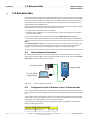
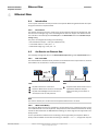
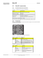
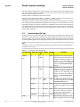
Physical Network Connection
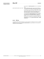
To minimize network latency, it is recommended that the I/O extension box is connected
directly to the Inspector PI50. The I/O box has a network switch so that a PC running SOPAS
Single Device can be connected via the I/O box.
I/O Extension box
Inspector PI50
PC with SOPAS
Single Device
Figure 2.1
2.2
Physical network connection
Configuration of the IP Address on the I/O Extension Box
This section briefly describes how to configure the I/O extension box for operation with the
Inspector PI50. For details, please refer to the user manual delivered with the I/O extension
box.
The IP address of the I/O extension box must be compatible with the addresses of the Inspector PI50 and of the PC. For details of how to set and view the IP address of the Inspector PI50,
please refer to the Operating Instructions for Inspector PI50.
The following is an example of how the IP addresses can be configured for the Inspector
PI50, the I/O box and the PC.
Inspector PI50 I/O Extension Box PC
192.168.1.110 192.168.1.3
10
192.168.1.30
©SICK AG • Advanced Industrial Sensors • www.sick.com • All rights reserved
Subject to change without notice
8014694/2012-08
Reference Manual
Inspector PI-series
I/O Extension Box
Interfaces
2.2.1
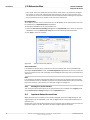
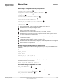
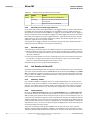
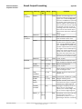
Basic Configuration of the IP address
The address selection switch on the I/O extension box configures the host part of the IP address, that is, the last of the four parts of the IP address. By default, the first three parts of
the address (also known as the network address) are set to 192.168.1. If the switch is set
to a value other than 0 (all switches set to Off) or 255 (all switches set to On), the I/O extension
box will use the host part of the IP address assigned by the switch.
Figure 2.2
Example
The setting above configures the I/O extension box to have a host ID of 3 corresponding to
the binary value “00000011” where switch 1 is bit 0 (LSB) and switch 8 is bit 7 (MSB). The
I/O box will then have an IP address of 192.168.1.3.
Advanced Configuration of the IP Address
If the network part of the IP address must be changed from the default 192.168.1 for the
I/O extension box, the internal web server of the I/O extension box can be used. For details
please refer to the manual delivered with the I/O extension box.
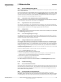
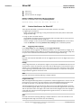
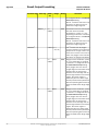
2.3
Setup of the I/O Extension Box in the SOPAS Single Device
Application
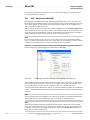
The communication with the I/O extension box is configured using the Interfaces and I/O Settings
dialog from the InspectorPI50 menu. Check the Digital I/O and I/O extension boxes in the Interfaces
tab. The I/O extension box is disabled if Ethernet is enabled in the same tab.
Figure 2.3
I/O Extension Box setup
Communication Mode
It is possible to adjust the way that the Inspector PI50 is communicating with the I/O extension
box. The settings are made in the I/O extension box setup tab in the Interfaces and I/O Settings
dialog from InspectorPI50 menu. There are three modes available:
• Robust mode. This is the default communication mode, and it is the recommended one if
the Inspector PI50 is connected to the SOPAS Single Device application during operation.
• Fast mode. This mode allows the Inspector PI50 to operate at a higher frame rate but there
is a risk that some data in the communication with the I/O extension box is lost if there is
high load on the network. This mode shall not be used if the Inspector PI50 is connected
to the SOPAS Single Device application during operation.
8014694/2012-08
©SICK AG • Advanced Industrial Sensors • www.sick.com • All rights reserved
Subject to change without notice
11
Interfaces
I/O Extension Box
Reference Manual
Inspector PI-series
• User mode. This is the advanced communication mode where it is possible to configure
the number of retries that the Inspector PI50 performs, and the timeout for each retry.
The timeout is the time (in milliseconds) that the Inspector PI50 is waiting for a reply from
the I/O extension box for a request to set outputs or read inputs.
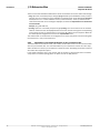
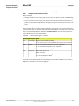
IP Configuration
To be able to connect to the I/O extension box, the IP address of the I/O extension box must
be specified in the SOPAS Single Device application.
To specify the IP address of the I/O extension box:
1. Open the Interfaces and I/O Settings dialog from the InspectorPI50 menu. Enter the selected
IP address of the I/O extension box setup tab in the four fields separated with dots.
2. Click Apply to store the settings.
Figure 2.4
Set up mode and IP address
Verify Connection
It is possible to verify that the connection to the I/O extension box can be established by
clicking the Verify connection button. The SOPAS Single Device application will then try to connect
to the I/O extension box, and a message will be displayed informing if the I/O extension box
was found.
Note
It is possible to configure the Inspector PI50 for use with the I/O extension box even when
the I/O extension box is not available. As soon as the Inspector PI50 detects the I/O extension
box on the network, it will connect to it and start using it as configured.
2.3.1
Enabling the I/O Extension Box
The use of the inputs and outputs on the I/O extension box is enabled on the Digital I/O tab
of the Interface and I/O Settings dialog from the InspectorPI50 menu.
2.4
Input and Output Connections
When delivered, the I/O extension box contains 4 digital inputs and 8 digital outputs. The
digital outputs can be expanded to 16, and the digital inputs of the Inspector PI50 can be
extended to 5.
Please refer to the manual delivered with the I/O extension box for details on how to connect
the power supply to the box, and where to find the digital inputs and outputs.
12
©SICK AG • Advanced Industrial Sensors • www.sick.com • All rights reserved
Subject to change without notice
8014694/2012-08
Reference Manual
Inspector PI-series
I/O Extension Box
Interfaces
2.4.1
Special Conditions During Startup
The following applies if the Inspector PI50 is configured to use the inputs of the I/O extension
box for object selection:
If the I/O extension box is not available when the Inspector PI50 starts up, the Inspector PI50
will use the last reference object selected in the SOPAS Single Device application before saving
to flash. Once the I/O extension box is available, the Inspector PI50 will read the inputs of
the box, and select the corresponding reference object.
2.4.2
Connection to the I/O Extension Box lost During Operation
If the connection to the I/O extension box is lost during operation, the last status of the inputs
on the box will be used until the connection is re-established.
2.4.3
Object Selection with I/O Extension Box
The status of the inputs on the I/O extension box is checked in the end of each inspection
cycle. If the Inspector PI50 is configured to use external image trig, the status of the external
inputs will only be checked when an image trig signal has been received.
2.4.4
Timing Issues
The digital outputs on the I/O extension box shall be read at minimum delay time as displayed
in the SOPAS Single Device application.
2.4.5
Use of the Digital Outputs for Logic
The digital outputs on the I/O extension box are not guaranteed to be jitter-free. It is not recommended to use these outputs for direct control of other devices. The I/O extension box
shall be connected to a PLC for process control.
2.4.6
Change of Modules in the I/O Extension Box
The Inspector PI50 supports I/O extension box configurations with up to 16 digital outputs
and 5 digital inputs (The standard configuration of the I/O extension box contains 8 digital
outputs and 4 digital inputs.). The configuration of an I/O extension box can be changed by
adding/removing I/O modules to/from the I/O extension box. I/O modules are available as
an accessory from SICK. For details about Accessories Ordering information see the Operating
Instructions for Inspector PI50.
Perform the following steps to connect and use more I/O modules:
1. Close the SOPAS Single Device application.
2. Disconnect the power from the I/O extension box.
3. Connect the additional I/O modules (inputs and/or outputs) to the I/O extension box.
Please refer to the manual delivered with the I/O extension box for details.
4. Re-connect the power to the I/O extension box.
5. Re-start the SOPAS Single Device application.
The additional digital outputs are now be available in the SOPAS Single Device application.
2.5
Troubleshooting
2.5.1
The I/O LED Flashes 10 Times
If the power to the I/O extension box has been disconnected for a longer period of time, the
internal clock in the box will be reset. The I/O LED on the box will then flash 10 times in red.
This is not a serious error, and the I/O extension box can still be used together with the Inspector PI50 without any problems.
2.5.2
No Contact with the I/O Extension Box
Ensure that the network card on the PC has the same network address, for instance
192.168.1, as the I/O extension box. The host part of the IP address (that is the last number
in the IP address) must not be the same as for the I/O extension box or the Inspector PI50.
8014694/2012-08
©SICK AG • Advanced Industrial Sensors • www.sick.com • All rights reserved
Subject to change without notice
13
Interfaces
I/O Extension Box
Reference Manual
Inspector PI-series
There are two tools available in Windows to check the network connection and the IP settings:
• Ping. Open the command prompt, and type ping followed by the IP address of the I/O extension box. If the I/O extension box is available the following text will be displayed: Reply from
x.x.x.x (where x.x.x.x is the IP address of the I/O extension box). If the I/O extension box
could not be found an error message is displayed, for instance Request timed out or Destination
host unreachable.
Example: ping 192.168.1.3
• Ipconfig. Open the command prompt and type ipconfig. The current status for the network
cards on the PC will then be displayed. Ensure that the network settings are corresponding
to the setting for the I/O extension box. The current IP address for the Inspector PI50 can
be viewed by selecting Device Info from the InspectorPI50 menu.
The web browser on the PC must be configured not to use a proxy when communicating with
the web server in the I/O extension box.
2.5.3
High Number of Unanswered Requests to the I/O Extension Box
The advanced communication mode, User mode, can be used to fine tune the communication
with the I/O extension box. It is recommended to try to increase the timeout as a first step,
and if this does not work, try to increase the number of retries. Increasing the number of retries
will reduce the inspection speed.
If the problem persists even if the timeout and the number of retries have been increased,
verify that the network topology does not block the use of UDP packets.
14
©SICK AG • Advanced Industrial Sensors • www.sick.com • All rights reserved
Subject to change without notice
8014694/2012-08
Reference Manual
Inspector PI-series
3
Web Interface
Interfaces
Web Interface
3.1
Introduction
The Web Interface is available in two variants: the Web API and the Web Server. The Web
API is used to create custom HMI solutions and offers a wide range of functions to control
and monitor the Inspector PI50. A subset of these functions is employed by the Web Server,
providing intuitive operation of the Inspector PI50 and high accessibility through a standard
web browser.
The command channel, shared with other interfaces, is available through the Web API as
well as specific functions to access images and to backup and restore configurations.
The Web Server interface is described in the Operating Instructions for Inspector PI50. The
Web API is described in this manual.
3.2
Get Results via Web API
The Web API presents the inspection results as overlay graphics in the live image. It is not
possible to get detailed inspection results through the Web API.
3.2.1
Live Image
The live image can be retrieved through the Web API by a live image request using the URL
http://<IP-address>/LiveImage.jpg The response to the request is a data buffer
containing a JPEG image.
If the image is not available, an empty image is returned with a smaller size than a normal
image.
Note
The live image is not available when SOPAS Single Device or the Inspector Viewer is connected
to the Inspector PI50.
Live image response can be much slower when activating the Send to FTP feature. The FTP
image transfer function has higher priority.
Example URLs
Request a live image without overlay graphics:
http://192.168.1.110/LiveImage.jpg
The response to the request is a data buffer containing a JPEG image.
Request a live image with overlay graphics:
http://192.168.1.110/LiveImage.jpg?ShowOverlay
3.2.2
Logged Images
Logged images can be retrieved using the URL http://<IP-address>/getP50LogImage?00
where the argument "00" is the image number. The image number is two digits in the range
[00, 29]. The device keeps writing to the log and therefore the log first has to be locked to
be able to retrieve an image. This is done by using the URL http://<IP-address>/LockLog
The response to the request is a data buffer containing a JPEG image. An empty image with
a smaller size than a normal image is returned if no log image is available for a certain position.
Example URL
http://192.168.1.110/LockLog
http://192.168.1.110/getP50LogImage?00
To start logging images again the log has to be unlocked first and this is done by using the
URL http://<IP-address>/LockLog?Unlock
8014694/2012-08
©SICK AG • Advanced Industrial Sensors • www.sick.com • All rights reserved
Subject to change without notice
15
Interfaces
Web Interface
Reference Manual
Inspector PI-series
Example URL
http://192.168.1.110/LockLog?Unlock
3.3
Control the Sensor via Web API
The Web API supports the command channel used to read and update parts of the device
configuration.
The Web API also supports the functionality to do a backup of the device configuration to a
file and to restore the configuration again. This is a convenient way to handle configurations
without installing and using SOPAS Single Device.
3.3.1
Basic Principles
The command channel has a set of basic principles:
• Only one command at a time can be executed.
• Each command is followed by a return message (ACK) that includes the result of the
command as well as error codes.
• The commands are not unique to a specific task, it is the commands together with its
parameters that uniquely points to a specific configuration change (see list of command
types and parameters in Appendix A,“Command Channel” (page 67)).
• Writing a parameter can typically only be done when the device is in Edit mode. Reading
a parameter can be done in both Edit and Run mode.
• It is possible to block configuration changes by unchecking the Allow changes via Web Server
checkbox in the Web Server tab in the dialog Interfaces and I/O Settings in InspectorPI50 menu.
3.3.2
Command Syntax
The Web API command channel has the following syntax:
http://<IP-address>/CmdChannel?<command>_<identifier>_<argument 1>_<argument 2>..._<argument N>
The ACK message has the following syntax:
<ACK Command> <identifier> <errorCode> <returnValue1> <returnValue2> ...
<returnValueN> <errorMessage>
The command is sent as an ASCII string. The combination of a command with its parameters
will either change the device configuration or fetch information from the device. For more
command examples see Section A.1, “Command Syntax” (page 67) and Section A.5, “Command Examples” (page 79).
Note
The command syntax differs from other interfaces where the initial part http://<IP-address>/CmdChannel? is added and all space characters (" ") are replaced by an underscore
character ("_"). The ACK messages still contain spaces.
Example URL
The successful execution of the following command
http://192.168.1.110/CmdChannel?sINT_1_1
will perform the command (to select reference object with index 1) and then return an HTML
page with a body containing the following string:
rsINT 1 0
while a failed command may return
rsINT 1 8100 Can not change ref bank in Run mode.
16
©SICK AG • Advanced Industrial Sensors • www.sick.com • All rights reserved
Subject to change without notice
8014694/2012-08
Reference Manual
Inspector PI-series
Web Interface
Interfaces
3.3.3
Current Reference Object
The reference image of the current reference object can be retrieved using the URL http://<IP-address>/ActiveReferenceImage.jpg
The response to the request is a data buffer containing a JPEG image.
Example URL
http://192.168.1.110/ActiveReferenceImage.jpg
3.3.4
Select Reference Object in Run mode
It is possible to select reference object also in Run mode.
The operation is a multiple step procedure that requires a login. The details of the procedure
is described in Appendix B,“Web API” (page 83).
Note
It is also possible to select reference object in Edit mode using the command channel, see
Section A.1, “Command Syntax” (page 67).
3.3.5
Backup and Restore Configuration
It is possible to backup and restore the device configuration through the Web API. This is the
same functionality also available through the standard web pages of the Web Server interface.
The backup data contains the device name and reference objects including corresponding
inspection and interface settings. Examples of data not included in the backup are IP address
and chessboard calibration settings.
Note
The backup and restore functionality of the Web Server and the Web API corresponds to the
Save Device File functionality of SOPAS Single Device. The file format created by the Web API is
not compatible with the ".sdv" file format.
Backup Configuration
The URL to export a configuration is http://<IP-address>/backup_config?config1
Example URL:
http://192.168.1.110/backup_config?config1
The result of the request is a buffer containing the device configuration. This file can be
stored in the file system of the receiving unit and used later in the restore procedure.
The Web Server standard web pages requires a login to perform a backup. A login is not required when doing a backup through the Web API.
Restore Configuration
The restore operation takes a device configuration created with the backup functionality and
replaces the current configuration with the configuration in the backup file.
The operation is a multiple step procedure that requires a login. The details of the procedure
is described in Appendix B,“Web API” (page 83).
The operation may take several minutes and the Inspector PI50 is automatically restarted
after the configuration has been transferred to the Inspector PI50.
Note
During the restore operation the device is set in a special restore mode only expecting restore
operation requests. Operations and requests via other interfaces like field buses, SOPAS
Single Device, Inspector Viewer or Web browsers (other than) shall then be avoided since
they may interfere with the restore operation.
8014694/2012-08
©SICK AG • Advanced Industrial Sensors • www.sick.com • All rights reserved
Subject to change without notice
17
Interfaces
Web Interface
3.4
Reference Manual
Inspector PI-series
Handle the Web API
The Web Server and Web API interfaces can be activated or deactivated. When activated, it
is possible to select port number and to allow command channel changes. The same settings
apply both to the Web Server and to the Web API. The Web interfaces are configured in the
Interfaces and I/O settings dialog in the InspectorPI50 menu.
The Web API is based on standard HTTP request and responses. Recommended request
timeout time is 3 seconds to allow for images to be transferred properly.
18
©SICK AG • Advanced Industrial Sensors • www.sick.com • All rights reserved
Subject to change without notice
8014694/2012-08
Reference Manual
Inspector PI-series
4
Ethernet Raw
Interfaces
Ethernet Raw
4.1
Introduction
To set up the connection and output results for Inspector PI50 using Ethernet Raw see Operating Instructions for Inspector PI50.
4.1.1
Port Interval
The default interval for the ports used by the communication channels is 2114-2116. This
interval can be changed, e.g. if the controlling device does not support the default interval.
The interval is controlled by the field Start port in the Ethernet Raw tab of the Interface and I/O
settings dialog.
The ports are assigned according to the following:
• Ethernet Result Output = start port (default 2114)
• Command channel = start port + 1
• Dedicated image trig = start port + 2
4.2
Get Results via Ethernet Raw
The following settings are done in the Ethernet Result Output dialog under Inspector PI50 menu.
4.2.1
TCP versus UDP
The basic difference between these protocols, for the Ethernet result output function, is which
side initiates the connection to receive/send the data.
TCP:
UDP:
PC/PLC initiates the connection
Inspector PI50 sends results to the PC/PLC
PC/PLC acknowledges that results are received (built into the TCP protocol)
Inspector PI50 sends results to the
specified IP address and port,
without knowing if it has been received
Note
For TCP the default port number that the Inspector PI50 listens to is 2114.
4.2.2
ASCII versus Binary
The Inspector PI50 supports the possibility to choose whether the configured output is to be
sent in ASCII format or in a binary format. The parameters that should be transferred in binary
format are also defined in the XML based formatting, but some tags are not supported in the
binary format.
If such a parameter is added to the formatting it will be ignored by the Inspector PI50. In
binary mode all added text and text formatting, for example <SPACE/>, are ignored. Only the
8014694/2012-08
©SICK AG • Advanced Industrial Sensors • www.sick.com • All rights reserved
Subject to change without notice
19
Interfaces
Ethernet Raw
Reference Manual
Inspector PI-series
values of the parameters describing results from the inspected images are sent out. For details
on which tags can be used in binary output see Section 7.2, “XML Formatting” (page 59).
4.2.3
Attributes
Attributes are used to control the formatting and identification of inspections. Some of them
can be controlled directly in the Ethernet Result Output dialog in the section Message settings. All
available attributes are listed in the table in section XML Formatting in Section 7.2, “XML
Formatting” (page 59).
Min number of digits
Choose the minimum number of digits (including decimal
point) to be sent out in the result. If the value to be sent out
has less number of digits, the result is padded with leading
zeros. Default value is 0 which means the number of digits
that will be sent will differ depending on how many digits are
needed. Note: This attribute is only applicable for ASCII
Number of decimals
Choose number of digits to be sent out after the decimal point
for parameters with decimals. This will be a rounded value.
Default value is 2. Max number of decimals is 9. Note: This
attribute is only applicable for ASCII
Degrees/Radians
Choose unit for the rotation for object locator and angle for
blobs.
Little/Big Endian
Only applicable when using binary format. This describes the
order of the bytes transferred from the device on Ethernet.
When using Little endian the least significant byte is transferred first and for Big endian the most significant byte is
transferred first. See the 2-byte example in tables below:
Value to be sent
from device:
Most significant
byte
Least significant
byte
10000100
01110000
Transfer order First transferred byte
Pixels/Millimeters
Second transferred
byte
Little endian
01110000
10000100
Big endian
10000100
01110000
Choose if position coordinates should be sent in pixel or millimeter unit. Note: The device must be calibrated for it to be
possible to use the “mm” attribute. An error message is given
in the output string if the device is not calibrated and mm is
chosen.
4.2.4
Default Formatting Strings
The auto-generated default string will look different depending on the configuration in the
selected reference object. The intention with the default string is to give an idea of the
available tags and to be a good starting point for creating the best format for the application
that should be solved.
Below follow some short descriptions of default strings, or part of default strings, for different
configurations. For more information about the XML formatting see Chapter 7, “Result Output
Formatting” (page 59).
20
©SICK AG • Advanced Industrial Sensors • www.sick.com • All rights reserved
Subject to change without notice
8014694/2012-08
Reference Manual
Inspector PI-series
Ethernet Raw
Interfaces
Default string for configuration with only an Object locator
<MESSAGE_SIZE/><NEWLINE/>
Image_number:<SPACE/><IMAGE_NUMBER/><NEWLINE/>
Object_locator.<NEWLINE/>
<OBJECT_LOC>
Located:<SPACE/><DECISION/><NEWLINE/>
Score:<SPACE/><SCORE/><NEWLINE/>
Scale:<SPACE/><SCALE/><NEWLINE/>
Position_(X,Y):<SPACE/>(<X/>,<Y/>)<NEWLINE/>
Rotation:<SPACE/><ROTATION/><NEWLINE/>
</OBJECT_LOC>
Size of the message, number of characters (ASCII) or bytes (binary)
Explanatory text and analyzed images number
Explanatory text
Start of container for object locator
Explanatory text and value for locator decision; 0=not found, 1=found
Explanatory text and locator score value, in percent how well of the object is found in
the object locator due to match settings
Explanatory text and locator scale value, factor of analyzed live image compared to
taught reference object
Explanatory text and x and y position of the reference point. This can be outside the
image and therefore negative. Shown in "pixels" or "mm"
Explanatory text and locator rotation, in degrees or radians depending on the configured
value in the Ethernet Result Output settings dialog
End of container for object locator
Result of validating output string with only an Object locator
The result of validating the default formatting output string with output format ASCII will be
as follows:
97
Image_number: 14471
Object_locator.
Located: 1
Score: 96.00
Scale: 1.00
Position_(X,Y): (291.52,238.55)
Rotation: 0.22
The result of validating the default formatting output string for only an object locator with
output format binary will be as follows:
Binary output OK. Number of bytes: 27
Part of default string for configuration with a Blob
Blob_tool.<NEWLINE/>
<BLOB index="0" name="Blob 1">
Found_blobs:<SPACE/><FOUND_BLOBS/><NEWLINE/>
-------------------------<NEWLINE/>
Blob_information:<NEWLINE/>
Position_(X,Y):<SPACE/>(<X/>,<SPACE/><Y/>)<NEWLINE/>
8014694/2012-08
©SICK AG • Advanced Industrial Sensors • www.sick.com • All rights reserved
Subject to change without notice
21
Interfaces
Ethernet Raw
Reference Manual
Inspector PI-series
Area:<SPACE/><AREA/><NEWLINE/>
Angle:<SPACE/><ANGLE/><NEWLINE/>
Structure:<SPACE/><EDGE_PIXELS/><NEWLINE/>
Touches_ROI_border:<SPACE/><EDGE_FLAG/><NEWLINE/>
</BLOB>
Explanatory text
Start of container for the blob tool named "Blob 1" and instruction to fetch the first (index="0") blob in accordance with the Sort by criteria
Explanatory text and number of found blobs in analyzed image
Separator
Explanatory text
Explanatory text and information of blob with index="0" concerning position and center
of gravity (x and y position), in "pixels" or "mm"
Explanatory text and blob (index="0") area, in "pixels"
Explanatory text and blob (index="0") angle value, in degrees or radians depending on
the configured value in the Ethernet Result Output settings dialog
Explanatory text and blob (index="0") structure value, number of edge pixels inside the
blob
Explanatory text and blob (index="0") edge value, 0=blob fully within ROI, 1= blob touches
ROI border
End of container for blob tool
Result of validating output string with a Blob
The result of validating the default formatting output string with output format ASCII will be
as follows:
Blob_tool.
Found_blobs: 16
------------------------Blob_information:
Position_(X,Y): (177.00, 156.89)
Area: 75
Angle: 154.33
Structure: 0
Touches_ROI_border: 0
The result of validating the default formatting output string for a blob with output format
binary will be as follows:
Binary output OK. Number of bytes: 28
Part of default string for configuration with a Polygon
Polygon1<POLYGON name="Polygon1"><NEWLINE/>
Corners:<SPACE/><NUM_CORNERS/><NEWLINE/>
<CORNERS corners="all">(X,Y):<SPACE/>(<X/>,<Y/>)<NEWLINE/>
</CORNERS>
</POLYGON>
Explanatory text and start of polygon container tag for the polygon tool named "Polygon
1"
Explanatory text and number of polygon corners
Start of container tag for polygon corners with instruction to loop over all polygon corners,
explanatory text, and corner position
End of container for polygon corners
22
©SICK AG • Advanced Industrial Sensors • www.sick.com • All rights reserved
Subject to change without notice
8014694/2012-08
Reference Manual
Inspector PI-series
Ethernet Raw
Interfaces
End of container for polygon
Result of validating output string with a Polygon
The result of validating the default formatting output string with output format ASCII will be
as follows:
Polygon_1
Corners: 4
(X,Y): (329.15,235.70)
(X,Y): (371.31,235.60)
(X,Y): (372.58,314.97)
(X,Y): (329.82,315.22)
The result of validating the default formatting output string for a polygon with output format
binary will be as follows:
Binary output OK. Number of bytes: 39
4.3
Control the Sensor via Ethernet Raw
The command channel makes it possible to read and write a defined set of configuration
parameters, and to trigger image acquisition, via UDP or TCP. This section describes how to
setup image triggering and command channel settings in SOPAS Single Device, as well as the
syntax of the command channel.
4.3.1
Basic Principles
The command channel has a set of basic principles:
• Only one command at a time can be executed.
• Each command is followed by a return message (ACK) that includes result of the command
as well as error codes.
• The commands are not unique to a specific task, it is the commands together with their
parameters that uniquely point to a specific configuration change (see list of command
types and parameters in Appendix A,“Command Channel” (page 67)).
• Writing a parameter can typically only be done when the device is in Edit mode. Reading
a parameter can be done in both Edit and Run mode.
• It is possible to block configuration changes by deselecting the setting Allow changes via
Ethernet Raw in the Ethernet Raw tab in the dialog Interfaces and I/O Settings in InspectorPI50
menu.
4.3.2
Command Syntax
The command channel has the following syntax:
<command> <identifier> <arg1> <arg2> ... <argN>
The ACK message has the following syntax:
<ACK Command> <identifier> <errorCode> <returnValue1> <returnValue2> ...
<returnValueN> <errorMessage>
The command is sent as an ASCII string. The combination of a command with its parameters
will either change the devices configuration or fetch information from the device. For more
command examples see Section A.5, “Command Examples” (page 79) and Section A.1,
“Command Syntax” (page 67).
4.3.3
Select Reference Object
To enable reference object selection via Ethernet Raw do the following:
1. Choose Interface and I/O Settings from the InspectorPI50 menu.
2. In the tab Interface choose Ethernet and Ethernet Raw in the listbox.
8014694/2012-08
©SICK AG • Advanced Industrial Sensors • www.sick.com • All rights reserved
Subject to change without notice
23
Interfaces
Ethernet Raw
Reference Manual
Inspector PI-series
To select reference object via command channel change to Edit mode, sMOD 1, change the
value to select the reference object, sINT 1 <object index> and then change back to
Run mode sMOD 0. The object index that corresponds to each reference object can be found
in the Reference object list in the Main view.
4.3.4
Image Trig
It is possible to trigger the image acquisition via Ethernet. The communication runs on UDP
or TCP port 2116 (configurable). In order to use this function the triggering has to be enabled
in SOPAS Single Device. In the InspectorPI50 menu and Interfaces and I/O settings dialog check the
Ethernet box and in the list Ethernet Raw in the Interfaces tab. For the selected reference object,
choose Triggered by Ethernet in the Image settings tab.
4.3.5
Single Port Solution
In real-time applications, the sensor is controlled using three ports. However, it is possible
to use only the command port (default 2115) to control the sensor. The single port solution
is only recommended for applications where the cycle time is significantly larger than the
image analysis time. One reason for this is that the image acquisition has a lower priority on
the command port. Another reason is that the Ethernet Result string must be retrieved from
the sensor, i.e. image trig and result handling cannot be performed in parallel when using
the single port solution.
This is how the sensor is controlled by using only the command port:
• The image acquisition is performed by the TRIG command (with lower priority).
• The Ethernet Result Output string is retrieved explicitly by the controlling device, e.g. a PLC.
This is done by the command gRES. The sensor does not send the result automatically on
this port.
• All other commands on the command channel are available as in the standard three port
solution
24
©SICK AG • Advanced Industrial Sensors • www.sick.com • All rights reserved
Subject to change without notice
8014694/2012-08
Reference Manual
Inspector PI-series
5
EtherNet/IP
Interfaces
EtherNet/IP
5.1
Introduction
The Inspector PI50 can be controlled and results
can be read out using the EtherNet/IP™ standard,
see http://www.odva.org/. To be able to do this
some settings have to be done first.
To set up the connection and output results for Inspector PI50 using Ethernet/IP see Operating
Instructions for Inspector PI50.
5.2
Get Results via Ethernet/IP
The following settings are done in the Ethernet Result Output dialog in the Inspector PI50 menu.
5.2.1
Attributes
Attributes are used to control the formatting and identification of inspections. Some of them
can be controlled directly in the Ethernet Result Output dialog in the section Message settings. All
available attributes are listed in the table in section XML Formatting in Section 7.2, “XML
Formatting” (page 59).
Degrees/Radians
Choose unit for the rotation for object locator and angle for blobs.
Pixels/Millimeters
Choose if position coordinates should be sent in pixel or millimeter unit. Note: The device must be calibrated for it to be possible to use the “mm” attribute. An error message is given in the
output string if the device is not calibrated and mm is chosen.
5.2.2
Example Formatting Strings
The auto-generated example string will look different depending on the configuration in the
selected reference object. The intention with the default string is to give an idea of the
available tags and to be a good starting point for creating the best format for the application
that should be solved.
Below follow some short descriptions of example strings, or part of default strings, for different
configurations. For more information about the XML formatting see Chapter 7, “Result Output
Formatting” (page 59).
Example string for configuration with only an Object locator
<IMAGE_NUMBER dataType="DINT" pos="0"/>
<OBJECT_LOC>
<DECISION dataType="SINT" pos="0"/>
<SCORE dataType="REAL" pos="0"/>
<SCALE dataType="REAL" pos="1"/>
<X dataType="REAL" pos="2"/>
<Y dataType="REAL" pos="3"/>
<ROTATION dataType="REAL" pos="4"/>
</OBJECT_LOC>
Analyzed image’s number
Start of container for object locator
Decision show if object is found (=1) or not found (=0)
8014694/2012-08
©SICK AG • Advanced Industrial Sensors • www.sick.com • All rights reserved
Subject to change without notice
25
Interfaces
EtherNet/IP
Reference Manual
Inspector PI-series
Score shown in percent how well of the object is found in the object locator due to match
setting
Scale is the factor of analyzed live image compared to taught reference object
Position (x) of the reference point of the object locator
Position (y) of the reference point of the object locator
Rotation of the object locator, in degrees or radians depending on the configured value
in the Ethernet Result Output dialog
End of container for object locator
Attribute dataType
Casts to the specified datatype. When using EtherNet/IP the attribute dataType specifies the dataType section in the selected
assembly. The attribute dataType can be SINT, INT, DINT or REAL.
For more details about dataType and pos see table in Section 7.3.2, “Attributes” (page 65).
Attribute pos
Used by EtherNet/IP to determine a position in the dataType
section in the selected assembly. The first position number of
the dataType section is 0. The range of the attribute pos depends
on which assembly is used. For example if assembly 1 and
dataType section SINT is selected the range of position is 8, i.e.
[0, 7]. For more details about dataType and pos see table in
Section 7.3.2, “Attributes” (page 65).
Therefore the value of the attributes dataType and pos together specifies which parameter
in the assembly the result value should be mapped to.
Result of validating output string with only an Object locator
The validating in SOPAS Single Device will give the following result:
EtherNet/IP assembly string OK.
Result in PLC with only an Object Locator
The table below describes how the Assembly 1's data structure will be populated when using
the configuration example above.
Position ref (pos)
Data type Offset byte Variable from
from XML configuration (dataType)
example above
26
0
SINT
0
1
SINT
1
2
SINT
2
3
SINT
3
4
SINT
4
5
SINT
5
6
SINT
6
7
SINT
7
0
INT
8
1
INT
10
2
INT
12
3
INT
14
4
INT
16
5
INT
18
6
INT
20
7
INT
22
DECISION
©SICK AG • Advanced Industrial Sensors • www.sick.com • All rights reserved
Subject to change without notice
8014694/2012-08
Reference Manual
Inspector PI-series
EtherNet/IP
Interfaces
Position ref (pos)
Data type Offset byte Variable from
from XML configuration (dataType)
example above
0
DINT
24
IMAGE_NUMBER
1
DINT
28
2
DINT
32
3
DINT
36
4
DINT
40
0
REAL
44
SCORE
1
REAL
48
SCALE
2
REAL
52
X
3
REAL
56
Y
4
REAL
60
ROTATION
Example string for configuration with only an Blob
<IMAGE_NUMBER dataType="DINT" pos="0"/>
<BLOB index="0" name="Blob 1">
<FOUND_BLOBS dataType="SINT" pos="0"/>
<X dataType="REAL" pos="0"/>
<Y dataType="REAL" pos="1"/>
<AREA dataType="DINT" pos="1"/>
<ANGLE dataType="REAL" pos="2"/>
<EDGE_PIXELS dataType="DINT" pos="2"/>
<EDGE_FLAG dataType="SINT" pos="1"/>
</BLOB>
Analyzed image’s number, attributes dataType and pos
Start of container for blob, Index number of the found blob according to current blob
sorting order. Index 0 is the first blob. Name refers to the blob tool's name in the Tools
tab
Number of found blobs
Blob center of gravity (x position), "pixels" or "mm"
Blob center of gravity (y position), "pixels" or "mm"
Blob area in pixels
Angle of the blob, in degrees or radians depending on the configured value in the Ethernet
Result Output dialog
Structure value (number of edge pixels inside the blob)
Edge flag: 0= the blob is fully within the ROI, 1=the blob touches ROI border
End of container for Blob
Attribute dataType
Casts to the specified datatype. When using EtherNet/IP the attribute dataType specifies the dataType section in the selected
assembly. The attribute dataType can be SINT, INT, DINT or REAL.
For more details about dataType and pos see table in Section 7.3.2, “Attributes” (page 65).
Attribute pos
Used by EtherNet/IP to determine a position in the dataType
section in the selected assembly. The first position number of
the dataType section is 0. The range of the attribute pos depends
on which assembly is used. For example if assembly 1 and
dataType section SINT is selected the range of position is 8, i.e.
8014694/2012-08
©SICK AG • Advanced Industrial Sensors • www.sick.com • All rights reserved
Subject to change without notice
27
Interfaces
EtherNet/IP
Reference Manual
Inspector PI-series
[0, 7]. For more details about dataType and pos see table in
Section 7.3.2, “Attributes” (page 65).
Therefore the value of the attributes dataType and pos together specifies which parameter
in the assembly the result value should be mapped to.
Result of validating output string with only an Blob
The validating in SOPAS Single Device will give the following result:
EtherNet/IP assembly string OK.
Result in PLC with only an Blob
The table below describes how the Assembly 1's data structure will be populated when using
the configuration example above.
Position ref (pos)
Data type Offset byte Variable from
from XML configuration (dataType)
example above
0
SINT
0
FOUND_BLOBS
1
SINT
1
EDGE_FLAG
2
SINT
2
3
SINT
3
4
SINT
4
5
SINT
5
6
SINT
6
7
SINT
7
0
INT
8
1
INT
10
2
INT
12
3
INT
14
4
INT
16
5
INT
18
6
INT
20
7
INT
22
0
DINT
24
IMAGE_NUMBER
1
DINT
28
AREA
2
DINT
32
EDGE_PIXELS
3
DINT
36
4
DINT
40
0
REAL
44
X
1
REAL
48
Y
2
REAL
52
ANGLE
3
REAL
56
4
REAL
60
Part of default string for configuration with only an Polygon
<IMAGE_NUMBER dataType="DINT" pos="0"/>
<POLYGON name="Polygon 1">
28
©SICK AG • Advanced Industrial Sensors • www.sick.com • All rights reserved
Subject to change without notice
8014694/2012-08
Reference Manual
Inspector PI-series
EtherNet/IP
Interfaces
<NUM_CORNERS dataType="SINT" pos="0"/>
<CORNERS corners="0">
<X dataType="INT" pos="1"/>
<Y dataType="INT" pos="2"/>
</CORNERS>
</POLYGON>
Analyzed image’s number, attributes dataType and pos
Start of container for Polygon, Name refers to the Polygon tool's name in the Tools tab
Number of corners used for this Polygon tool
Number 0 to 15 gives the properties of a single corner. The index of this corner is the
order in which the polygon corner was added when the polygon was drawn
Polygon corner coordinate (x), "pixels" or "mm"
Polygon corner coordinate (y), "pixels" or "mm"
End of tag for corners
End of container for Polygon
Attribute dataType
Casts to the specified datatype. When using EtherNet/IP the attribute dataType specifies the dataType section in the selected
assembly. The attribute dataType can be SINT, INT, DINT or REAL.
For more details about dataType and pos see table in Section 7.3.2, “Attributes” (page 65).
Attribute pos
Used by EtherNet/IP to determine a position in the dataType
section in the selected assembly. The first position number of
the dataType section is 0. The range of the attribute pos depends
on which assembly is used. For example if assembly 1 and
dataType section SINT is selected the range of position is 8, i.e.
[0, 7]. For more details about dataType and pos see table in
Section 7.3.2, “Attributes” (page 65).
Therefore the value of the attributes dataType and pos together specifies which parameter
in the assembly the result value should be mapped to.
Result of validating output string with only and Polygon
The validating in SOPAS Single Device will give the following result:
EtherNet/IP assembly string OK.
If the used assembly is too small the validating will give the following result:
EtherNet/IP assembly string not OK. Out of slots for data type INT
Use a larger assembly to solve this problem . Choose a larger assembly in the dialog Interfaces
and I/O settings in the InspectorPI50 menu and the EtherNet/IP tab.
Result in PLC with only an Polygon
The table below describes how the Assembly 1's data structure will be populated when using
the configuration example above.
Position ref (pos)
Data type Offset byte Variable from
from XML configuration (dataType)
example above
8014694/2012-08
0
SINT
0
1
SINT
1
2
SINT
2
3
SINT
3
NUM_CORNERS
©SICK AG • Advanced Industrial Sensors • www.sick.com • All rights reserved
Subject to change without notice
29
Interfaces
EtherNet/IP
Reference Manual
Inspector PI-series
Position ref (pos)
Data type Offset byte Variable from
from XML configuration (dataType)
example above
5.3
4
SINT
4
5
SINT
5
6
SINT
6
7
SINT
7
0
INT
8
X
1
INT
10
Y
2
INT
12
3
INT
14
4
INT
16
5
INT
18
6
INT
20
7
INT
22
0
DINT
24
1
DINT
28
2
DINT
32
3
DINT
36
4
DINT
40
0
REAL
44
1
REAL
48
2
REAL
52
3
REAL
56
4
REAL
60
IMAGE_NUMBER
Control the Sensor via EtherNet/IP
The Inspector PI50 has the following EtherNet/IP characteristics:
• Device type: Communication adapter
The Inspector PI50 relies on a Scanner device to set up the communication channel. The
IP address of the Inspector PI50 can be found by choosing Device Info from the InspectorPI50
menu.
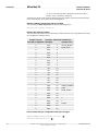
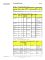
• Assemblies Instance no. Size (bytes) Comment
Assembly no.
Output
100
4
Slim command channel
Input
101
36
Command channel result
Output
102
32
Command channel
Input
103
64
Small result channel
1
Input
105
124
Medium result channel
2
Input
107
248
Large result channel
3
Input
109
484
Extra large result channel 4
• Minimum RPI: > 16 ms.
When retrieving inspection results via EtherNet/IP, the time between two inspections
should be at least twice the RPI (Requested Packet Interval) specified for the communication
channel.
30
©SICK AG • Advanced Industrial Sensors • www.sick.com • All rights reserved
Subject to change without notice
8014694/2012-08
Reference Manual
Inspector PI-series
EtherNet/IP
Interfaces
With the shortest possible RPI, the highest recommended inspection rate is therefore approximately 30 Hz.
The EDS file for the Inspector PI50 can be found in the Documentation folder on the Inspector
CD.
The Inspector PI50 has two Output assemblies that can be used for controlling the Inspector
PI50. To do this the connection has to be set first, see Operating Instructions for Inspector
PI50.
The slim command channel assembly (instance no. 100) is used for controlling the Inspector
PI50 in the following ways:
• Select reference object
• Image trig
The command channel assembly (instance no. 102) is also used for controlling the Inspector
PI50. With this assembly you have access to all functions in the command channel, see
Section A.2, “Command descriptions” (page 68).
The two output assemblies are described in detail, see Section 5.3.6, “Assemblies Command
Channel” (page 33).
5.3.1
Basic Principles
The command channel has a set of basic principles:
• In order to be able to change the configuration via Ethernet/IP this must be enabled. This
is done In the dialog Interfaces and I/O Settings from the InspectorPI50 menu. Check Ethernet
and EtherNet/IP in the tab Interfaces. In the same dialog and tab EtherNet/IP check Allow
changes via EtherNet/IP.
• It is possible to block configuration changes by deselecting the setting Allow changes via
Ethernet/IP in the Ethernet/IP tab in the dialog Interfaces and I/O Settings in InspectorPI50 menu.
• Writing a parameter can typically only be done when the device is in Edit mode. Reading
a parameter can be done in both Edit and Run mode.
• The commands is sent with help of output assembly 102 and the result is received with
input assembly 101.
• The result for a sent command can be received at the earliest in the next PLC cycle. The
PLC program will have to wait for the result of an undefined number of seconds.
• Make sure that the PLC program waits for a response with the same command and ID as
the sent command. If the command response never shows up a timeout must be implemented. This is done by sending another command for example gVER.
5.3.2
Command Syntax
To send commands through the command channel use the output assembly 102. The command channel has the following syntax:
<command> <identifier> <arg1> <arg2> <arg3> <arg4> <arg5> <arg6>
Replace <command> with the commands id, see Table A.3, “Command ID numbers - for EtherNet/IP and EtherCAT” (page 68).
The result of a command, sent over output assembly 102, can be received through input
assembly 101. The syntax for ACK message is:
<command>
<identi- <error
fier>
code>
<retV- <retV- <retV- <retV- <retV- <retVal1>
al2>
al3>
al4>
al5>
al6>
The combination of a command with its parameters will either change the devices configuration or fetch information from the device. For more command examples see Section A.1,
“Command Syntax” (page 67) and Section A.5, “Command Examples” (page 79).
8014694/2012-08
©SICK AG • Advanced Industrial Sensors • www.sick.com • All rights reserved
Subject to change without notice
31
Interfaces
EtherNet/IP
Reference Manual
Inspector PI-series
5.3.3
Select Reference Object
There are two ways to select reference object with EtherNet/IP and command channel.
The first way to select reference object:
To select the reference object via the slim command channel, change the value of Select
reference object in the slim command channel assembly (instance no. 100). The object
index that corresponds to each reference object can be found in the Reference object list in
the Main view.
If the value in Select reference object does not correspond to any reference object,
the Inspector PI50 will ignore the attempt to switch reference object.
The second way to select reference object:
To select reference object via command channel change to Edit mode, 0 0, change the value
to select the reference object, 2 1 <object index> and then change back to Run mode 0
1 in the command channel assembly (instance no. 102). The object index that corresponds
to each reference object can be found in the Reference object list in the Main view.
The time it takes to switch reference object depends on the number of inspections, inspection
type, and sizes of the regions in the reference object. Typically it takes in the order of one
second to switch reference object. For more information see Operating Instructions for Inspector PI50.
5.3.4
Image Trig
To enable triggering via EtherNet/IP, do the following:
1. Choose Interfaces and I/O Settings from the InspectorPI50 menu.
2. In the tab Interface choose Ethernet and EtherNet/IP in the list box.
3. In the Image settings tab choose Trig by EtherNet/IP.
To trigger an image acquisition via EtherNet/IP, specify that the slim command channel (instance no. 100) is to be used here and set the value of Trigger to 1. The image capture is
made immediately, without any delays.
The Inspector PI50 will capture an image each time the value of Trigger is changed to 1
(i.e. rising edge). To trigger the next image caption, you must first set the value to 0.
When triggering via EtherNet/IP, the time between two image captions should be at least 4
times the RPI. This means that the maximum triggering rate via EtherNet/IP is approximately
15 Hz.
5.3.5
Input Assemblies, Result Channel
There are four input assemblies, each assembly corresponds to respective assembly in the
EtherNet/IP tab in the Interfaces and I/O Settings dialog. Each assembly has four different dataType
sections, SINT, INT, DINT, and REAL. Each dataType section has a different number of positions, the number of positions depends on the assembly and the dataType selected. Example:
The dataType SINT in assembly 1 has 8 positions [0, 7] and the dataType REAL in assembly
4 has 44 positions [0, 43]. The contents of the assembly are defined from the Ethernet Result
Output dialog.
Note
On the installation CD there is an excel file with templates for the four result input assemblies
(file name: AssemblyMappingPI50.xls). These can be used to document the mapping between
position in data structure and what is configured in the Ethernet Result Output dialog.
Assembly 1 - Small Result Channel
Instance ID:
103
Size:
64 bytes
32
©SICK AG • Advanced Industrial Sensors • www.sick.com • All rights reserved
Subject to change without notice
8014694/2012-08
Reference Manual
Inspector PI-series
EtherNet/IP
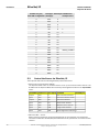
Table 5.1
Interfaces
Input Assembly 1
Datatype Number/ size Offset (bytes) Total size
SINT
8/ 1 byte each 0
8 bytes
INT
8/ 2 bytes each 8
16 bytes
DINT
5/ 4 bytes each 24
20 bytes
REAL
5/ 4 bytes each 44
20 bytes
Assembly 2 - Medium Result Channel
Instance ID:
105
Size:
124 bytes
Table 5.2
Input Assembly 2
Datatype
Number/ size
Offset (bytes) Total size
SINT
12/ 1 byte each 0
12 bytes
INT
12/ 2 bytes each 12
24 bytes
DINT
11/ 4 bytes each 36
44 bytes
REAL
11/ 4 bytes each 80
44 bytes
Assembly 3 - Large Result Channel
Instance ID:
107
Size:
248 bytes
Table 5.3
Input Assembly 3
Datatype
Number/ size
Offset (bytes) Total size
SINT
24/ 1 byte each 0
24 bytes
INT
24/ 2 bytes each 24
48 bytes
DINT
22/ 4 bytes each 72
88 bytes
REAL
22/ 4 bytes each 160
88 bytes
Assembly 4 - Extra Large Result Channel
Instance ID:
109
Size:
484 bytes
Table 5.4
Input Assembly 4
Datatype
Number/ size
Offset (bytes) Total size
SINT
44/ 1 byte each 0
44 bytes
INT
44/ 2 bytes each 44
88 bytes
DINT
44/ 4 bytes each 132
176 bytes
REAL
44/ 4 bytes each 308
176 bytes
5.3.6
Assemblies Command Channel
The Output assembly contains two parameters that are used for selecting reference object
and trigger inspections.
The value that corresponds to each reference object can be found in the Reference object list
in the Main view.
8014694/2012-08
©SICK AG • Advanced Industrial Sensors • www.sick.com • All rights reserved
Subject to change without notice
33
Interfaces
EtherNet/IP
Reference Manual
Inspector PI-series
Slim Command Channel
Instance ID:
100
Size:
4 bytes
Table 5.5
Slim Command channel
Data
Type Offset (bytes)
Values
Select reference object SINT 0
0-31: Selected reference object
Trigger
SINT 1
1: Trigger inspection.
Set to 0 before triggering next inspection.
Reserved
SINT 2
Reserved
SINT 3
Command Channel
Instance ID:
102
Size:
32 bytes
Table 5.6
Data
102 output, Command channel
Type Offset (bytes)
Command
DINT 0
Identifier
DINT 4
Argument 1 DINT 8
Argument 2 DINT 12
Argument 3 DINT 16
Argument 4 DINT 20
Argument 5 DINT 24
Argument 6 DINT 28
Command Channel Result
Instance ID:
101
Size:
36 bytes
Note
If a Class 1 connection has been made to the device it is recommended to use the gVer
command as a Noop (no operation) command.
Table 5.7
Data
101 input Command channel result
Type Offset (bytes)
Command
DINT 0
Identifier
DINT 4
Error code
DINT 8
Returnvalue 1 DINT 12
Returnvalue 2 DINT 16
Returnvalue 3 DINT 20
Returnvalue 4 DINT 24
Returnvalue 5 DINT 28
34
©SICK AG • Advanced Industrial Sensors • www.sick.com • All rights reserved
Subject to change without notice
8014694/2012-08
Reference Manual
Inspector PI-series
EtherNet/IP
Data
Interfaces
Type Offset (bytes)
Returnvalue 6 DINT 32
8014694/2012-08
©SICK AG • Advanced Industrial Sensors • www.sick.com • All rights reserved
Subject to change without notice
35
Interfaces
6
EtherCAT
Reference Manual
Inspector PI-series
EtherCAT
6.1
Introduction
The Inspector PI50 ECAT can be operated as an
EtherCAT® aslave device in an EtherCAT network.
This means that the Inspector PI50 can be controlled and results can be read out in an EtherCAT
network. For more general information about
EtherCAT see http://www.ethercat.org/.
a
EtherCAT® is registered trademark and patented technology, licensed by Beckhoff Automation GmbH, Germany.
The EtherCAT interface for the Inspector PI50 ECAT is always enabled and the specific settings
for EtherCAT can be done in SOPAS Single Device, see Operating Instructions for Inspector PI50.
The Inspector PI50 ECAT has been verified in an EtherCAT network using the TwinCAT® 2.x
Master from Beckhoff, see http://www.beckhoff.com. All examples in this manual uses
TwinCAT as Master.
6.2
EtherCAT Function Overview
The Inspector PI50 ECAT interfaces an EtherCAT network in the following way:
Table 6.1
EtherCAT function overview
Inspector PI50 ECAT feature EtherCAT mapping
Inspection result
Process data, see section Section 6.4, “Get Results via EtherCAT” (page 38)
Illumination trig
Process data, see section Section 6.4.4, “Illumination trig
output” (page 41)
Inspection trig
Process data, see section Section 6.5.1, “Triggering of the
Inspector” (page 44)
Command channel
CoE (Command over EtherCAT), see section Section 6.5.2,
“Using the CoE command channel” (page 45)
Web server/Web API
EoE (Ethernet over EtherCAT), see section Section 6.6, “EoE
- Web server/Web API” (page 48)
Configuration handling (upload/download)
FoE (File access over EtherCAT), see section Section 6.7,
“FoE - Configuration Handling and Firmware Download” (page 49)
Firmware handling (download) FoE (File access over EtherCAT), see section Section 6.7,
“FoE - Configuration Handling and Firmware Download” (page 49)
How the different Inspector PI50 ECAT features are used in an EtherCAT network are described
in following sections.
36
©SICK AG • Advanced Industrial Sensors • www.sick.com • All rights reserved
Subject to change without notice
8014694/2012-08
Reference Manual
Inspector PI-series
EtherCAT
Interfaces
6.3
EtherCAT communication
6.3.1
EtherCAT Communication Specification
Table 6.2
EtherCAT Communication Specification
Feature
Specification
Communication protocol EtherCAT protocol (ETG.1000)
Modulation method
Baseband
Transmission speed
100Mbps
Physical layer
100BASE-TX (IEEE802.3)
Connector
Two M12. X1 EtherCAT in. X2 EtherCAT out.
Communication medium CAT5 or higher
Communication distance Distance between nodes (slaves): 100m or less
6.3.2
EtherCAT LED:s
Figure 6.1, “EtherCAT LED on the Inspector PI50 ECAT” (page 37) shows the EtherCAT LED
on the Inspector PI50 ECAT.
/Act
Run
/Act
X2
X1
Err
Figure 6.1
Table 6.3
EtherCAT Run indicator LED
Color
Status
Details
Green
Off
Device in INIT mode
Blinking
Device in PRE-OPERATIONAL mode
Single flash
Device in SAFE-OPERATIONAL mode
On
Device in OPERATIONAL mode
Table 6.4
8014694/2012-08
EtherCAT LED on the Inspector PI50 ECAT
EtherCAT Err indicator LED
Color
Status
Details
Red
Off
No error
Blinking
General configuration error
Single flash
Local slave error
Double flash
Application watchdog timeout
On
Critical error
©SICK AG • Advanced Industrial Sensors • www.sick.com • All rights reserved
Subject to change without notice
37
Interfaces
EtherCAT
Table 6.5
Reference Manual
Inspector PI-series
EtherCAT Link/Act indicator LED for X1/X2
Color
Status
Details
Green
Off
Physical link layer not established
Flashing
Physical link layer established and data
is being sent
On
Physical link layer established
6.3.3
EtherCAT process data toggle indicators
For the EtherCAT process data objects (PDO:s) one toggle indicator is used for data between
the Master and the Inspector (Rx Toggle bit for the RxPDO:s) and one toggle indicator for
data between the Inspector and the Master (Tx toggle bit for the TxPDO:s). The Rx Toggle indicator is implemented as one single bit (toggle bit) and will toggle each time any of the RxPDO:s have been updated, and the Tx Toggle indicator is implemented as three bits and will
toggle each time any of the TxPDO:s have been updated. See Section Section 6.10, “PDO
Overview” (page 54) for a summary of PDO:s.
The purpose of the toggle indicators is to indicate that data have been updated and that it
should be read by the Master or the Inspector respectively.
6.3.4
EtherCAT cycle time
The following two conditions have to be fulfilled related to the selected EtherCAT cycle time:
1. Minimum EtherCAT cycle time is 0.5ms. Verified using a single Inspector PI50 in an EtherCAT network running a typical inspection at an inspection cycle of 5Hz and using a process
data size of 64bytes.
2. Assure that the EtherCAT cycle time is maximally one fourth of the Inspection cycle time.
For example, running a fast inspection with an Inspection cycle time of 20ms (50Hz),
results in a maximal EtherCAT cycle time of 20/4 = 5ms.
The EtherCAT cycle time is set by the EtherCAT Master.
6.4
Get Results via EtherCAT
The Inspector PI50 ECAT generates an inspection result every inspection cycle. The Inspection
cycle time can be calculated from the Frame rate (Hz) found under the Live image in the SOPAS
GUI. In an EtherCAT network the Inspection result is mapped to EtherCAT process data (PD)
using a number of TxPDO:s (Tx Process Data Objects). Two types of result PDO:s exist, mandatory PDO:s and optional PDO:s.
6.4.1
Mandatory TxPDO:s
Five mandatory TxPDO:s are always used in the Inspector PI50 ECAT. This means that the
inspection result sent to the Master in these PDO:s are always there, i.e. they cannot be deselected. The TxPDO:s used are Status, Mode, Time Stamp, Early Time Stamp, and Image
Number. See section Section 6.10, “PDO Overview” (page 54) for a summary of TxPDO:s.
6.4.2
Optional TxPDO:s
By using the Ethernet Result Output dialog under InspectorPI50ECAT menu in SOPAS Single Device
the user can select a set of inspection results that are output in each inspection cycle. An
XML formatting string defines what inspection results to output in each inspection cycle. To
output this user selectable inspection result in the EtherCAT network it is mapped to optional
TxPDO:s. Depending on the total size of the inspection result selected by the XML formatting
string, the EtherCAT user has to select the appropriate set of optional TxPDO:s to match the
required size. That is, the size of the selected optional TxPDO:s has to be at least the size of
the selected inspection result output.
There exist six different sized optional TxPDO:s that the user can select from, sizes are
16bytes, 32bytes, 64bytes, 128bytes, 256bytes, and 512bytes. Any combination of these
differently sized optional TxPDO:s can be selected, but only one of the same size. This means
38
©SICK AG • Advanced Industrial Sensors • www.sick.com • All rights reserved
Subject to change without notice
8014694/2012-08
Reference Manual
Inspector PI-series
EtherCAT
Interfaces
that the maximal size of the inspection result output selected by the XML formatting string
is 16+32+64+128+256+512 = 1008bytes. That is, it is possible to select any total size
between 0 and 1008bytes in step of 16bytes. Note that the selection of optional TxPDO:s
are done from the EtherCAT Master side.
Mandatory TxPDO
(14 bytes)
Selected optional
TxPDO
Available optional
TxPDO:s
16
32
64
128
256
512
Figure 6.2
Selecting optional TxPDO:s for the result
The order the inspection results appear in the XML formatting string is also the order that
they will appear in the selected set of optional TxPDO:s. The size in bytes of the selected inspection result can be found in Section 7.3, “Container Specific Tags” (page 60). To ease
for the PLC programmer a function block generator is available that makes the mapping
between the XML formatting string and variables in a PLC program, see Section Section 6.11,
“ESI file” (page 57).
Figure 6.3, “Mapping results into the optional TxPDO” (page 39) shows an example how the
XML formatting string maps data into a selected set of optional TxPDO:s along with the
mandatory TxPDO:s.
Mandatory TxPDO (14 bytes)
Optional TxPDO (size set by EtherCAT master)
Figure 6.3
Mapping results into the optional TxPDO
See Section Section 6.10, “PDO Overview” (page 54) for a summary of TxPDO:s.
8014694/2012-08
©SICK AG • Advanced Industrial Sensors • www.sick.com • All rights reserved
Subject to change without notice
39
Interfaces
EtherCAT
Reference Manual
Inspector PI-series
6.4.3
Results via EtherCAT - Work flow
Typically the following steps are done in order to map the XML formatting string specified
inspection results to EtherCAT optional TxPDO:s.
Configure your inspection
Start with configuring your inspection, see Part 2, "How To" in the Operating Instructions.
Select inspection results to output
Open the dialog Ethernet Result Output under the InspectorPI50ECAT menu.
The active reference object is selected by default in the Reference object entry.
The Message settings represents the default units that will be used for inspection results.
Degrees/Radians
Choose unit for the rotation for object locator and angle for blobs.
Pixels/Millimeters
Choose if position coordinates should be sent in pixel or millimeter unit. Note: The device must be calibrated for it to be possible to use the “mm” attribute. An error message is given in the
output string if the device is not calibrated and mm is chosen.
Note that the units can be individually changed for specific inspection results by the use of
attributes to the result tag:s. All available attributes are listed in the table in section Section 7.2, “XML Formatting” (page 59).
Enter the result output formatting string in the Formatting string for Ethernet Output window or
click the Create example formatting string button to create an example formatting string. Edit the
string to adjust it if necessary.
Validate and find the size of the XML output string
In the Ethernet Result Output dialog click the Validate output string button. A text will now appear
in the Current output string window that will indicate any syntax errors in the XML formatting
string.
The text will also display the required size in bytes for the inspection result defined by the
XML-string. That is, this is the size that the optional TxPDO:s have to match.
Below are three examples of validated output string in SOPAS Single Device when...
• The Master has selected a total size for the optional TxPDO:s that is too small. Optional
TxPDO size is in this example 16bytes and the required size form the XML formatting string
is 57bytes.
Error: Result string too long. Max size: 16 Size: 57
• The Master has not any selected optional TxPDO:s
Error: No PD containers selected from Master, formatting string
cannot be used. Required size: 57 bytes
• The Master has not yet reported an optional TxPDO sizes yet (e.g. Master not on-line).
Warning: Master has not reported PD size yet, cannot validate
formatting string size.
Note that the Master need to set the Inspector into OPERATIONAL mode in order for the
optional TxPDO-size to be transferred to the Inspector.
Select the correct TxPDO size on the EtherCAT Master
Based on the reported size for the inspection result select a combination of optional TxPDO:s
on the Master side that is at least equal to this size.
Example of validated output string in SOPAS Single Device when the TxPDO:s size is big enough
to fit the XML formatting string selected inspection results.
EtherCAT binary output OK. Max size: 80 Size: 57
40
©SICK AG • Advanced Industrial Sensors • www.sick.com • All rights reserved
Subject to change without notice
8014694/2012-08
Reference Manual
Inspector PI-series
EtherCAT
Interfaces
In the above example the 16byte and the 64byte optional TxPDO:s have been selected by
the Master (totally 80bytes), and this is enough to fit the required 57bytes. Note that it also
would have been sufficient to select only the 64byte optional TxPDO.
Note that the maximal size of XML formatting string inspection output is 1008bytes. If this
limit is exceeded the following is displayed.
Error: Formatting string specifies more data than supported by the
Inspector (1008 bytes). Required size: 1024 bytes
6.4.4
Illumination trig output
The mandatory TxPDO Status (see Section Section 6.10, “PDO Overview” (page 54)) contains
one bit for Illumination trig. This bit is typically used for triggering external illumination sources
controlled by the EtherCAT Master when the Inspector is not triggered by the Master.
The Illumination trig bit is a toggle bit where every toggle of the bit indicates a time point from
where there is a defined time left until the exposure of the next image will start. This is outlined
in Figure 6.4, “Illumination trig” (page 41).
#1
#2
#1
#2
t
Exposure
Analysis
Illumination trig bit
Figure 6.4
EtherCAT cycles
Inspector's inspection cycle time
Illumination trig for the next exposure
Illumination trig
As seen in Figure 6.4, “Illumination trig” (page 41) the Inspector will trigger an EtherCAT Illumination trig that is valid for the next image at the same time as the current image starts its
exposure. Note that since the EtherCAT cycle is not correlated to the inspection cycle the
actual toggle of the Illumination trig bit can be delayed one or two EtherCAT cycles (depending
on EtherCAT cycle time) before it reaches the Master. This means that when the Inspector
initiate to send out the Illumination trig the time left until the exposure starts is the actual
Inspector cycle time. In order to turn on the illumination in time before the exposure starts
the user should account for the possible EtherCAT cycle delay.
Note
It is possible to read out the inspection cycle time via the CoE command channel. See Section A.2, “Command descriptions” (page 68).
6.4.5
Example Formatting Strings
The auto-generated example string will look different depending on the configuration in the
selected reference object. The intention with the example string is to give an idea of the
available tags and to be a good starting point for creating the best format for the application
that should be solved.
Below follow some short descriptions of example strings for different configurations. For more
information about the XML formatting see Chapter 7, “Result Output Formatting” (page 59).
8014694/2012-08
©SICK AG • Advanced Industrial Sensors • www.sick.com • All rights reserved
Subject to change without notice
41
Interfaces
EtherCAT
Reference Manual
Inspector PI-series
It is possible to verify the actual size of the output result defined by the XML formatting string.
This is done by validating the output string in the Ethernet Result Output dialog. Assign the appropriate Inspection Result PDO:s in the EtherCAT Master, see Table 6.9, “PDO overview” (page 55).
Example string for configuration with only an Object locator
<MESSAGE_SIZE/>
<IMAGE_NUMBER/>
<OBJECT_LOC>
<DECISION/>
<SCORE/>
<SCALE/>
<X/>
<Y/>
<ROTATION/>
</OBJECT_LOC>
Size of the message (bytes)
Analyzed images number
Start of container for object locator
Value for locator decision; 0=not found, 1=found
Locator score value, in percent how well of the object is found in the object locator due
to match settings
Locator scale value, factor of analyzed live image compared to taught reference object
X position of the reference point. This can be outside the image and therefore negative.
Shown in "pixels" or "mm"
Y position of the reference point. This can be outside the image and therefore negative.
Shown in "pixels" or "mm"
Locator rotation, in degrees or radians depending on the configured value in the Ethernet
Result Output settings dialog
End of container for object locator
Result of validating output string with only an Object locator
Example of validated output string in SOPAS Single Device:
EtherCAT binary output OK. Max size: 240 Size: 27
Example string for configuration with only an Blob
<MESSAGE_SIZE/>
<IMAGE_NUMBER/>
<BLOB index="0" name="Blob 1">
<FOUND_BLOBS/>
<X/>
<Y/>
<AREA/>
<ANGLE/>
<EDGE_PIXELS/>
<EDGE_FLAG/>
</BLOB>
42
©SICK AG • Advanced Industrial Sensors • www.sick.com • All rights reserved
Subject to change without notice
8014694/2012-08
Reference Manual
Inspector PI-series
EtherCAT
Interfaces
Size of the message (bytes)
Analyzed images number
Start of container for the blob tool named "Blob 1" and instruction to fetch the first (index="0") blob in accordance with the Sort by criteria
Number of found blobs in analyzed image
information of blob with index="0" concerning position and center of gravity (x position),
in "pixels" or "mm"
information of blob with index="0" concerning position and center of gravity (y position),
in "pixels" or "mm"
Blob (index="0") area, in "pixels"
Blob (index="0") angle value, in degrees or radians depending on the configured value
in the Ethernet Result Output settings dialog
Blob (index="0") structure value, number of edge pixels inside the blob
Blob (index="0") edge value, 0=blob fully within ROI, 1= blob touches ROI border
End of container for blob tool
Result of validating output string with only an Blob
Example of validated output string in SOPAS Single Device:
EtherCAT binary output OK. Max size: 240 Size: 28
Example string for configuration with only an Polygon
<MESSAGE_SIZE/>
<IMAGE_NUMBER/>
<POLYGON name="Polygon 1">
<NUM_CORNERS/>
<CORNERS corners="0">
<X/>
<Y/>
</CORNERS>
<CORNERS corners="1">
<X/>
<Y/>
</CORNERS> 12
<CORNERS corners="2">
<X/>
<Y/>
</CORNERS>
</POLYGON> 13
Size of the message (bytes)
Analyzed images number
Start of polygon container tag for the polygon tool named "Polygon 1"
Number of corners used for this polygon
Start of container tag for polygon corners with instruction to loop over all polygon corners
Corner position, X
Corner position, Y
End of container for polygon corners
Same as 5
Same as 6
8014694/2012-08
©SICK AG • Advanced Industrial Sensors • www.sick.com • All rights reserved
Subject to change without notice
43
Interfaces
EtherCAT
12
13
Reference Manual
Inspector PI-series
Same as 7
Same as 8
End of container for polygon
Result of validating output string with only an Polygon
Example of validated output string in SOPAS Single Device:
EtherCAT binary output OK. Max size: 240 Size: 19
6.5
Control the Sensor via EtherCAT
The Inspector PI50 ECAT is controlled in an EtherCAT network in two ways.
1. Triggering of the Inspector
Either in process data (PD Trig) or using the Distributed Clock (DC) feature of EtherCAT
(Programmable Trig).
2. Using the CoE command channel
The available commands used for the EtherCAT CoE command channel can be found in
Appendix A,“Command Channel” (page 67).
To allow changes via the command channel Allow changes via EtherCAT has to be checked
in the tab EtherCAT in the dialog Interfaces and I/O Settings. This is enabled by default.
6.5.1
Triggering of the Inspector
In the Image settings tab under Triggering choose Triggered by EtherCAT.
An inspection can be triggered in an EtherCAT network in two ways. Either by a trigger bit in
the mandatory RxPDO Control (PD Trig), see Section Section 6.10, “PDO Overview” (page 54))
or by the use of the Distributed Clock feature of EtherCAT (Programmable Trig).
Note
Note that the Inspector PI50 ECAT can still be triggered by the use of the digital input in3 (if
enabled).
PD Trig
A low-to-high transition on the Inspection Trig bit in the process data (RxPDO Control) will tell
the Inspector to start an inspection cycle. Note that the PD Trig has a time resolution that is
related to the used EtherCAT cycle. That is, the Trig can only occur at discrete times related
to the beginning of each EtherCAT cycle. If better time resolution is required for the Trig the
Programmable Trig feature should be used.
Note
Note that the Process data Trig (PD Trig) is always enabled.
Programmable Trig
With the Programmable Trig feature it is possible for the PLC programmer to set the time for
the Trig to occur. The time is set with reference to the EtherCAT Distribute Clock (DC) time.
DC mode of operation in the EtherCAT network has to be enabled by the Master.
The PLC programmer sets the time for the Trig to occur in the StartTime register, and then
sets the Activate register. When the Trig has occurred the Activate register has to be set low,
and the procedure starts over again. This means that the PLC programmer cannot program
a new Trig time until the previously programmed Trig has occurred, i.e. there is no queue
handling of Trig times.
Note
Note that the Process data Trig (PD Trig) is always enabled. It is not recommended to use
the Programmable Trig at the same time as the PD Trig.
44
©SICK AG • Advanced Industrial Sensors • www.sick.com • All rights reserved
Subject to change without notice
8014694/2012-08
Reference Manual
Inspector PI-series
EtherCAT
Interfaces
For more details see Section 6.8.2, “Programmable Trig” (page 52).
6.5.2
Using the CoE command channel
Basic principles:
• Writing a parameter can typically only be done when the device is in Edit mode. Reading
a parameter can be done in both Edit and Run mode.
• A new command can not be sent until the previous command has been completed. It is
possible to download and upload files (using FoE) though a command has not been completed.
CoE Command Syntax
The command channel uses the protocol CANopen over Ethernet (CoE), and the standard
CoE Command Object is used (see ETG.1020, Command Object). The index used for the CoE
object in the EtherCAT Master is 0x2000, callCommandChannel. The table below shows the
used subindices for the Command Object.
Table 6.6
CoE Command Object - subindex
Subindex Description Value
01
Command
Byte 0-n: Service Request Data
A write access to the command data will execute the command
02
Status
1: Last command completed, no errors, reply there
3: Last command completed, error, reply there
255: Command is executing
03
Response
Byte 0: See subindex 2
Byte 1: Unused
2-n: Service Response Dataa
a
See Figure 6.6, “Subindex 3, Response” (page 47)
The syntax for the EtherCAT CoE command channel (Command, Subindex 01) is shown in
Figure 6.5, “Subindex 1, Command” (page 46).
8014694/2012-08
©SICK AG • Advanced Industrial Sensors • www.sick.com • All rights reserved
Subject to change without notice
45
Interfaces
EtherCAT
Reference Manual
Inspector PI-series
Subindex 1
MSB
LSB
Byte 1
Byte 0
Byte 3
Byte 2
Byte 5
Byte 4
Byte 7
Byte 6
Byte 9
Byte 8
Byte 11
Byte 10
Byte 13
Byte 12
Byte 15
Byte 14
Byte 17
Byte 16
Byte 19
Byte 18
Byte 21
Byte 20
Byte 23
Byte 22
Byte 25
Byte 24
Byte 27
Byte 26
Byte 29
Byte 28
Byte 31
Byte 30
Figure 6.5
3
2 command 1
0
7
6 identifier 5
4
11
10
arg1
9
8
15
14
arg2
13
12
19
18
arg3
17
16
23
22
arg4
21
20
27
26
arg5
25
24
31
30
arg6
29
28
Subindex 1, Command
• command
Replace command with the commands id, see Table A.3, “Command ID numbers - for
EtherNet/IP and EtherCAT” (page 68).
• identifier
Replace identifier with commands identifier found in Section A.2, “Command descriptions” (page 68).
• arg1-arg6
Replace arg1-arg6 with the argument required for the selected command. Unused arguments will be ignored and is therefore not necessary to set.
CoE Response syntax
The syntax for the EtherCAT CoE command channel (Response, Subindex 03) is shown in
Figure 6.6, “Subindex 3, Response” (page 47).
46
©SICK AG • Advanced Industrial Sensors • www.sick.com • All rights reserved
Subject to change without notice
8014694/2012-08
Reference Manual
Inspector PI-series
EtherCAT
Interfaces
Subindex 3
MSB
5
9
13
177
21
25
29
33
37
107
Figure 6.6
4 replyCommand 3
8 identifier 7
12 errorCode 11
16 retVal1 15
20 retVal2 19
24 retVal3 23
28 retVal4 27
32 retVal5 31
36 retVal6 35
resultString
2
6
10
14
18
22
26
30
34
LSB
Byte 1
Unused
Byte 0
Status
Byte 3
Byte 2
Byte 5
Byte 4
Byte 7
Byte 6
Byte 9
Byte 8
Byte 11
Byte 10
Byte 13
Byte 12
Byte 15
Byte 14
Byte 17
Byte 16
Byte 19
Byte 18
Byte 21
Byte 20
Byte 23
Byte 22
Byte 25
Byte 24
Byte 27
Byte 26
Byte 29
Byte 28
Byte 31
Byte 30
Byte 33
Byte 32
Byte 35
Byte 34
Byte 37
Byte 36
Byte 39
Byte 38
Byte 107
Byte 106
38
Subindex 3, Response
Byte 0 in the Response message is the Status byte (see Subindex 2 in Table 6.6, “CoE
Command Object - subindex” (page 45)) and can be either 1= OK or 3 = not OK.
• replyCommand
An echo of the command sent.
• identifier
An echo of the identifier sent.
• errorCode
In case the command ended with an error this is the reported error code, see Section A.3,
“Error Codes” (page 77).
• retVal1-retVal6
The return value, if such exists for the executed command, see Section A.2, “Command
descriptions” (page 68).
• resultString
In case the command ended with an error resultString is an ASCII description of the error.
8014694/2012-08
©SICK AG • Advanced Industrial Sensors • www.sick.com • All rights reserved
Subject to change without notice
47
Interfaces
EtherCAT
Reference Manual
Inspector PI-series
For command examples see Section A.1, “Command Syntax” (page 67) and Section A.5,
“Command Examples” (page 79).
6.6
EoE - Web server/Web API
By enabling the EtherCAT feature EoE, Web server/Web API traffic can be tunneled in the
EtherCAT network instead of being routed in the Fast Ethernet interface (Ethernet connector).
This means that you do not need to use the Fast Ethernet cable if the only usage for this
cable is Web server/Web API traffic.
EoE can only be enabled or disabled in the EtherCAT Master and not in SOPAS Single Device or
with any command in the command channel. The IP address used for EoE tunneling must
not be the same as the IP address used for the Fast Ethernet interface. Further the EoE interface and the Fast Ethernet interface cannot be on the same sub-net.
Note
In this release the Web server has to run on the same computer as the EtherCAT Master
runs, e.g. the PC that TwinCAT runs on. This means that it is not possible to connect a laptop
computer to the Master computer and run the Web server on the laptop.
Figure 6.7, “Configuring IP address in TwinCAT System Manager for using EoE” (page 48)
show an example of configuring EoE in TwinCAT System Manager.
Figure 6.7
Configuring IP address in TwinCAT System Manager for using EoE
The IP address entered is the IP address used for the EoE traffic. That is, this is the IP address
that the Web server should use to connect to the Inspector over EoE. Note that this is not
the same IP address as the Inspector IP address used for the SOPAS connection.
The only Inspector PI50 ECAT traffic that can be tunneled via EoE is the Web server/Web API
traffic, i.e. SOPAS Single device and Store images to FTP traffic only works on the Fast Ethernet
interface.
Note
The fact that EoE has been disabled is not reported by TwinCAT to the Inspector PI50 ECAT.
This means that the Inspector PI50 ECAT will still respond on the EoE channel.
Note
Depending on EtherCAT network settings and the Inspector configuration used, the Web
server live image frame rate can be lower than the default vale of 1fps. If this happens no
live image, or a sporadic live image, will be shown. Increase the Refresh interval to get a live
image that is updated continuously.
48
©SICK AG • Advanced Industrial Sensors • www.sick.com • All rights reserved
Subject to change without notice
8014694/2012-08
Reference Manual
Inspector PI-series
EtherCAT
Interfaces
6.6.1
Error Codes - EoE
The table below list error codes that may result from commands or configuration of the device.
The error codes are valid for EoE.
Table 6.7
Error codes valid for EoE
Error code propagated Description
to EtherCAT Master
0x0
No error
0x1
Error in IP address, could be one of:
• Trying to use the same IP address as the one already used for
Fast Ethernet
• Trying to use a broad cast address as IP address
• Trying to use 0.0.0.0
• Trying to use the local host address, 127.0.0.1
• Trying to use a reserved address; 240.0.0.0/4
0x1
Invalid subnet mask
0x1
Invalid gateway
0x1
Trying to enable DHCP which is not implemented
0x1
EtherCAT support in Inspector PI50 ECAT is not initialized. This
usually points to a hard ware error
0x1
EtherCAT module internal error
Note
Due to limitations in the Inspector PI50 ECAT EtherCAT slave controller implementation, all
EoE errors reported from the Inspector PI50 ECAT is mapped to an unspecified error (0x1)
on the EtherCAT Master side.
6.7
FoE - Configuration Handling and Firmware Download
In the EtherCAT Master it is possible to download (to the Inspector) a device configuration
file or a firmware file to the Inspector PI50 ECAT. It is also possible to upload (to the Master)
a device configuration file using the FoE mechanism. To be able to do file transfers the Inspector PI50 ECAT has to be set into BOOTSTRAP mode.
Note
To be able to go into BOOTSTRAP mode the Inspector has to be in Edit mode. Edit mode can
be set via the CoE command channel or the SOPAS GUI.
An FoE transfer can take in the range of minutes. As an example a 3.6Mbyte large file takes
90seconds when having an EtherCAT cycle time of 2ms.
8014694/2012-08
©SICK AG • Advanced Industrial Sensors • www.sick.com • All rights reserved
Subject to change without notice
49
Interfaces
EtherCAT
Figure 6.8
Reference Manual
Inspector PI-series
File transfers in TwinCAT System Manager
6.7.1
FoE Download (to Inspector)
To start a FoE download supply the file name and the FoE password (a 32bit integer). Factory
default setting for the FoE password is "0". One FoE password is used for all types of FoE
transfers. The password can be set via an EtherCAT command, see Table A.5, “Command
channel - only for EtherCAT” (page 69). In TwinCAT System Manager an FoE download is
started by clicking the Download... button in Figure 6.8, “File transfers in TwinCAT System
Manager” (page 50). A file selection dialog then appears where the desired file for download
is selected. After that a new dialog appears where the FoE-password must also be supplied.
Note that TwinCAT has in this dialog stripped the file extension so it has to be entered back
by hand.
A file downloaded with the file extension .s0 will be regarded as a firmware download, and
all other file extensions will be regarded as a configuration download. If a downloaded configuration file is invalid the device will automatically be re-booted, and the last configuration
saved in Flash will be used.
A device configuration file created with the Backup command in the Web server/Web API (see
Section 3.3.5, “Backup and Restore Configuration” (page 17)) can be used for FoE configuration download. Vice versa, an FoE saved configuration file can be used by the Web server/Web API Restore command.
Note
When downloading a configuration to the Inspector, the Inspector will automatically be restarted after the configuration has been stored in flash. When downloading new FW to the Inspector the FW is stored in flash, but the user himself have to reset the Inspector in order
for the new FW to be used.
6.7.2
FoE Upload (to Master)
A configuration file can be uploaded to the EtherCAT Master, i.e. saved in the file system of
the EtherCAT Master. To start an upload supply the file name to use and the FoE password
(same password as for downloads). In TwinCAT System Manager an FoE upload is started by
clicking the Upload... button in Figure 6.8, “File transfers in TwinCAT System Manager” (page 50). A file selection dialog then appears where the desired file for download is
selected. After that a new dialog appears where the FoE password must be supplied. Note
that TwinCAT has in this dialog also stripped the file extension but the file will still be named
as selected in the initial dialog.
50
©SICK AG • Advanced Industrial Sensors • www.sick.com • All rights reserved
Subject to change without notice
8014694/2012-08
Reference Manual
Inspector PI-series
EtherCAT
Interfaces
6.7.3
FoE Error Codes
Below is a list of the used EtherCAT FoE error codes. Note that FoE is only allowed in BOOTSTRAP mode.
Table 6.8
Error codes valid for FoE
Error code propagated
to EtherCAT Master
Description
0x00000000
No error
0x00008000
When writing the firmware file (Application, FPGA, EtherCAT) to
the Inspector PI50 ECAT Flash memory an error occurred
0x00008002
The password provided for FoE access does not match the password stored for FoE usage
0x00008004
This error occurs if an FoE transfer is attempted in Run mode or
if the FoE file format is wrong. The file format can be wrong due
to the following reasons:
• Wrong file extension. Use “*.s0” for firmware files (Application,
FPGA, EtherCAT)
• “*.s0” header indicated wrong firmware file type, i.e. not Application, FPGA, or EtherCAT
• Wrong product type code in the “*.s0” firmware file
0x00080008
Inspector PI50 ECAT is not in BOOTSTRAP mode which is required
for the FoE operation
0x0000800B
FoE file checksum error. The checksum of the transferred file
could not be validated on the Inspector PI50 ECAT.
Note! If using TwinCAT the error codes are not propagated to the GUI or PLC level due to the
implementation of TwinCAT.
6.8
DC - Distributed Clock (DC) features
EtherCAT Distributed Clock (DC) mode has to be enabled in the EtherCAT Master before this
feature can be used.
The Time Stamp feature and Programmable Trig feature utilizes the DC feature of the EtherCAT
network.
The DC features in an EtherCAT network assures that all slaves supporting DC has a common
reference time. One of the DC capable slaves in the EtherCAT network holds the Reference
Clock and the other DC capable slaves each holds a Local Clock to which drift and offset
compensation are applied in order to align to the common Reference Clock.
Normally the Reference Clock is a 64bit value representing the offset from a Jan 1 2000,
where one bit (tick) represents 1ns. A 64bit value will then give a wrap-around time of about
500years. Due to limitations in the EtherCAT Slave Controller in the Inspector this value is
instead a 32bit value. Therefore the wrap-around time is about 4.2seconds in the Inspector.
This has to be handled by the PLC programmer.
6.8.1
Time Stamp
The Time Stamp feature is a way to know at which DC time the image started its exposure.
After the exposure of the image the inspection result will be calculated, and finally the inspection result is sent out. The inspection result will be paired with the corresponding 32bit Time
Stamp value and sent out in the TxPDO Time Stamp. Another TxPDO, Early Time Stamp, will
send out the time stamp value as fast as possible on the EtherCAT network. Figure 6.9, “Time
Stamp and Early Time Stamp” (page 52) shows an example of this.
8014694/2012-08
©SICK AG • Advanced Industrial Sensors • www.sick.com • All rights reserved
Subject to change without notice
51
Interfaces
EtherCAT
Reference Manual
Inspector PI-series
#1
#2
#3
#2
#1
#1
#2
#3
#3
t
#1
#1
#2
#1
#2
#2
Exposure
Analysis
EtherCAT cycles
Inspection result TxPDO
Figure 6.9
#3
Time stamp TxPDO
Early time stamp TxPDO
The Inspector updates the time stamp
when starting a new inspection
Time Stamp and Early Time Stamp
6.8.2
Programmable Trig
The Programmable Trig feature is a way for the user to program an EtherCAT Distributed
Clock (DC) time when he wants the Inspector to be triggered. In this way the user is not bound
to trigger the Inspector upon an EtherCAT cycle basis, i.e. as part of the process data (see
PD Trig), instead the trigger time can freely be chosen. The Programmable Trig feature is a
single shot feature, meaning that you actively have to set the DC time for each trigger event.
From an EtherCAT network perspective the Programmable Trig feature is implemented by
using the EtherCAT Distributed Clock single shot SYNC0 event.
Enable Programmable Trig
The DC feature used to implement the Programmable Trig feature has to be enabled by the
Master. In TwinCAT SystemManager this is done by selecting the Inspector box and in the DC
tab select the Operation Mode DC Single Shot event. Also make sure that the Distributed Clock
dialog in the Advanced Settings... on the DC tab has the following settings:
• Operation Mode: DC Single Shot Event and Enable selected
• SYNC 0: Enable SYNC 0
SYNC 0 - Cycle Time: User Defined selected.
Programmable Trig is by default disabled in the Inspector. Programmable Trig is enabled in
the EtherCAT tab in the Interfaces and IO settings dialog in the Inspector PI50 menu in SOPAS by
checking the box Enable Programmable Trig.
Note
The use of the Programmable Trig feature and the Trig bit in the process data are allowed
simultaneously. However it is recommended to only use one of the features in a configuration.
Using Programmable Trig
The Programmable Trig feature is programmed using the two EtherCat Slave Controller (ESC)
registers StartTime (0x990) and Activate (0x981) on the Inspector. The PLC programmer
accesses these registers by using the PDO DC Sync Activate and PDO DC Sync Start PDO:s, see
Section 6.10, “PDO Overview” (page 54).
52
©SICK AG • Advanced Industrial Sensors • www.sick.com • All rights reserved
Subject to change without notice
8014694/2012-08
Reference Manual
Inspector PI-series
EtherCAT
Interfaces
#2
#1
T1
StartTime=T1
Activate=3
T2
StartTime=T2
Activate=0
Activate=3
Imager exposure
Programmable Trig signal
DC time
Figure 6.10
t
Activate=0
EtherCAT cycles
Delay from Programmable Trig to Imager
exposure
Pulse width of Programmable Trig, fix
value of 500 μs
Illumination trig
Figure 6.10, “Illumination trig” (page 53) shows how the Programmable Trig feature is used.
The following procedure can be used:
1. Make sure the Activate register is set to 0x0.
2. Set the time, T1, when you want the Trig to occur in the StartTime register (0x990).
3. In the next EtherCAT cycle, set the Activate register (0x981) to 0x3.
4. When the rising edge of the Trig has occurred set the Activate register to 0x0. Go back to
step "2".
Note that when the Programmable Trig occurs (the StartTime equals the Distributed Clock
time) there is a delay of approximately 60µs until the exposure of the image starts, indicated
as Trig to exposure delay in Figure 6.10, “Illumination trig” (page 53). This delay varies to
some extent and the maximum measured delay is 90µs and the minimum delay is 50µs. If
SOPAS is connected to the Inspector the delay is increased to approximately 70µs with a
maximum delay of 120µs and a minimum delay of 50µs.
Note
Note that the DC time of the Inspector is kept in a 32bit register and thus have a wrap-around
of approximately 4.2 seconds. This has to be handled in the PLC program.
6.9
EtherCAT related constants and variables
6.9.1
Station Alias
In an EtherCAT network, slaves are automatically assigned addresses based on their position
in the network. But when the device must have a positive identification that is independent
of cabling, a Station Alias is needed. For Inspector PI50 ECAT, the Station alias is configured
in the EtherCAT Master and stored in the Inspector PI50 ECAT. When the Inspector PI50 ECAT
is reset to factory default, the Station Alias will also be reset to its default value, but a reboot
of the Inspector PI50 ECAT is needed for the default value to take effect.
The default Station Alias value is "0".
8014694/2012-08
©SICK AG • Advanced Industrial Sensors • www.sick.com • All rights reserved
Subject to change without notice
53
Interfaces
EtherCAT
Reference Manual
Inspector PI-series
6.9.2
Vendor Id
The Vendor Id is 0x01000056 for SICK AG. The Vendor Id is available at CoE index 0x1018,
subindex 1. The Vendor Id will never change.
6.9.3
Revision Number
The Revision Number is used to match the ESI-file to the EtherCAT Slave Controller firmware
version. If the Revision Number in the ESI-file does not match the Revision Number in the
EtherCAT Slave Controller the Master will signal an error. The Revision Number is available
as a constant at CoE index 0x1018, subindex 3.
6.9.4
Serial Number
The Serial Number is the serial number of the Inspector PI50 ECAT. It can be read out as a
constant at CoE address 0x1018, subindex 4.
6.9.5
Device Type
The EtherCAT device type is set to 0x0. The Device Type is available as a constant at CoE
index 0x1000.
6.9.6
Manufacturer Hardware Version
The hardware version number, available as a constant at CoE index 0x1009.
6.9.7
Manufacturer Software Version
The EtherCAT Slave Controller software version, available as a constant at CoE index 0x100A.
6.10
PDO Overview
Note! When using trigged mode it is necessary to send a trig or change mode to update the
content of the PDO:s.
Note! All PDO:s (Process Data Object) contain one single PDO entry. This means that the size
of the PDO is always equal to the size of the PDO entry. Some PDO entries define bits that
have different meanings. For example, the mandatory Time stamp TxPDO is four bytes and
the PDO entry is also four bytes representing the time stamp only. Whereas the mandatory
Status TxPDO is one byte and the PDO entry (also one byte) defines different meanings for
the bits in the byte.
54
©SICK AG • Advanced Industrial Sensors • www.sick.com • All rights reserved
Subject to change without notice
8014694/2012-08
Reference Manual
Inspector PI-series
EtherCAT
Table 6.9
Interfaces
PDO overview
Direc- PDO
tion
Transmit from Inspector PI50 ECAT Receive from EtherCAT Master
(TxPDO)
(RxPDO)
PDO Control (1 byte)a
PDO entry - details
Size of PDO entries
Rx Toggle Bit (bit 0)
1 bit
Inspection Trig (bit 1), PD Trig 1 bit
Bit 2-7 not used
6 bits
PDO DC Sync Activate (1 byte)
Activate (bit2-bit7 not used)
1 byte
PDO DC Sync Start (4 bytes)
Start Time
4 bytes
PDO Status (1 byte) a
Tx Toggle Bits (bit 0-2)
3 bit
Illumination Trig (bit 3)
1 bit
All Passed (bit 4)
1 bit
Not Located (bit 5)
1 bit
Detail Inspection Failed (bit 6) 1 bit
PDO Mode (1 byte)
a
PDO Time Stamp (4 bytes)
a
Bit 7 not used
1 bit
Mode
1 byte
Time Stamp
4 bytes
PDO Early Time Stamp (4 bytes) Early Time Stamp
4 bytes
PDO Image Number (4 bytes) a Image Number
4 bytes
a
System Time
4 bytes
PDO Inspection Result 16 (16
bytes)
Byte0...Byte15
16 bytes
PDO Inspection Result 32 (32
bytes)
Byte0...Byte31
32 bytes
PDO Inspection Result 64 (64
bytes)
Byte0...Byte63
64 bytes
a
PDO Sys Time (4 bytes)
PDO Inspection Result 128 (128 Byte0...Byte127
bytes)
128 bytes
PDO Inspection Result 256 (256 Byte0...Byte255
bytes)
256 bytes
PDO Inspection Result 512 (512 Byte0...Byte511
bytes)
512 bytes
a
Mandatory PDO
Process Data from EtherCAT Master to Inspector (RxPDO)
Detailed explanation:
PDO Control
Control byte. Contains Rx Toggle bit and Inspection Trig
(PD Trig). One toggle bit for all RxPDO:s. All PDO entries
in Control are mandatory process data.
Rx Toggle bit
Toggle flag. The RX Toggle bit has to be toggled each
time the RxPDO has been updated or changed. Bit 0 in
the Control byte.
8014694/2012-08
©SICK AG • Advanced Industrial Sensors • www.sick.com • All rights reserved
Subject to change without notice
55
Interfaces
EtherCAT
Inspection Trig (PD Trig)
PDO DC Sync Activate
PDO DC Sync Start
Reference Manual
Inspector PI-series
Contains the inspection trigger. Changing the Inspection
Trig-bit from 0 to 1 will trigger the Inspector PI50 ECAT.
Bit 1 in the Control byte.
This is the Activate register for the Programmable Trig
feature. See Section 6.8, “DC - Distributed Clock (DC)
features” (page 51).
This is the programmed DC StartTime for the Programmable Trig feature. See Section 6.8, “DC - Distributed
Clock (DC) features” (page 51).
Process Data from Inspector to EtherCAT Master (TxPDO)
Detailed explanation:
PDO Status
Status byte. Contains Tx Toggle Bits, Illumination Trig,
All Pass, Not Located and Detail Inspection Failed. All
PDO entries in Status are mandatory process data.
Tx Toggle bits
The three-bit word changes value each time any TxPDO
has been updated. Bit 0-2 in the Status byte.
Illumination Trig
The toggling of this bit will represent an illumination trig.
Illumination trig is only sent in free-running mode. To
use illumination trig the External lighting has to be set in
SOPAS Single Device. Check the box for External in Image
settings tab under Lighting. Bit 3 in the Status byte. See
Figure 6.4, “Illumination trig” (page 41) for the timing
of Illumination trig.
All Passed
1= The object was located and all detailed inspection
passed as well. Bit 4 in the Status byte.
Not Located
1=The object was not located or a detailed inspection
was out of view. Bit 5 in the Status byte.
Detail Failed
1= The object was located but at least one of the detailed inspections failed. Bit 6 in the Status byte.
PDO Mode
The mode of the Inspector PI50 ECAT. 0=Run, 1=Edit.
This is a mandatory PDO.
PDO Time Stamp
The Time Stamp is sent out with the corresponding inspection result for an image. The Time Stamp represents
the time when the imager started its acquisition for the
inspected image. The Time Stamp is only valid if the
EtherCAT DC (Distributed Clock) mode is enabled. If DC
mode is not used or the Inspector is in Edit mode the
Time Stamp value is undefined. This is a mandatory
PDO.
PDO Early Time Stamp
Early Time Stamp carries the same information as the
Time Stamp. The difference is that the Early Time Stamp
is sent out as soon as possible after the start of image
acquisition. That is, the Early Time Stamp is sent out
before the corresponding inspection result. As with the
Time Stamp, the Early Time Stamp is only defined in the
EtherCAT DC mode and when the Inspector is in Run
mode. This is a mandatory PDO.
PDO Sys Time
System Time in the Inspector, 32bit representation.
PDO Image Number
Contains the image number. The image number is restarted at 0 for each boot of the Inspector PI50 ECAT
and each reset to factory defaults. Image number reflects each image taken. Mandatory process data. Note
that there will be no image number if there are no refer-
56
©SICK AG • Advanced Industrial Sensors • www.sick.com • All rights reserved
Subject to change without notice
8014694/2012-08
Reference Manual
Inspector PI-series
EtherCAT
PDO Inspection Result (16...512)
6.11
Interfaces
ence objects in SOPAS Single Device. This is a mandatory
PDO.
Choose which PDO entries to use for the inspection
result defined by the XML formatting string. It is possible
to choose one or more Inspection Result PDO. Each Inspection Result PDO can only be chosen once. The assignments for each Inspection Result PDO is done in
the EtherCAT Master. These are optional PDO:s.
The total size of the selected Inspection Result PDO:s
is only updated in SOPAS Single Device when the Inspector
PI50 ECAT does the transition PREOP to SAFEOP or
PREOP to OP. The total size of the selected Inspection
Result PDO:s is needed when validating the XML output
format string in the dialog Ethernet Result Output in SOPAS
Single Device.
ESI file
The ESI (EtherCAT Slave Information) file for the Inspector is located on the CD in the /documentation-folder and is named Inspector PI50 ECAT.ESI.xml. Copy the ESI-file to the location required by the EtherCAT Master.
8014694/2012-08
©SICK AG • Advanced Industrial Sensors • www.sick.com • All rights reserved
Subject to change without notice
57
Appendix
Reference Manual
Inspector PI-series
7
Result Output Formatting
Appendix
Result Output Formatting
7.1
XML Based Formatting
The formatting of the result string is defined by a formatting string written in XML. It is possible
to mix XML tags and free text in the formatting string. The text parts will appear as is in the
result string, whereas the XML tags will be replaced by the appropriate values. All white
spaces in the formatting strings are ignored. In order to include whitespace in the result string
use the tags <SPACE/>, <TAB/> and <NEWLINE/>.
The tags are either container tags or value tags. The container tags do not generate any text
on their own. It is the value tags inside the container tags that generate the text. The following
container tags are valid in the Inspector PI50:
Container tag
Explanation
OBJECT_LOC
Used to present values concerning the Object locator
BLOB
Used to present values for a found blob in a blob ROI. The index
points out the found blob in accordance with the blob sorting
order. If no index is given this is the same as index = 0.
PIXEL_COUNTER, PATTERN, Used to present values concerning inspections.
EDGE_PIXEL_COUNTER
POLYGON
Used to present values concerning a defined Polygon
CORNERS
Container tag within the <POLYGON> tag for presenting values
concerning the polygon corners. See example:
<POLYGON>
<CORNERS>
<X/>,<Y/>
</CORNERS>
</POLYGON>
The XML based formatting string is entered in the Formatting string for Ethernet Output part of
the Ethernet Result Output dialog. To get a default string for the current chosen reference object
click Create default formatting string. Click Validate output string to validate the formatting string.
The output that will be sent over Ethernet or errors are reported in the Current output string part
of the Ethernet Result Output dialog.
Note
When using binary transfer, the Validate output string button will only show how many bytes
that will be sent for the current analyzed image and whether the formatting was correct or
not.
The maximum size of the XML buffer is 7900 ASCII characters. This means it will not be
possible to e.g. paste a XML string into to the input field if it's too large. For a larger configuration it might not be possible to configure as much output information as wanted due to this
limitation.
7.2
XML Formatting
The content of the Ethernet output is configured using an XML-based formatting string. The
available tags can be categorized into two groups:
• container tags: <OBJECT_LOC>, <POLYGON>, <BLOB>
• value tags: <X/>, <PIXELS/>, <NEWLINE/>, <TIME/>,...
8014694/2012-08
©SICK AG • Advanced Industrial Sensors • www.sick.com • All rights reserved
Subject to change without notice
59
Appendix
Result Output Formatting
Reference Manual
Inspector PI-series
The value tags are replaced with a value whereas the container tags are used to group value
tags. The container tags do not generate any text on their own. It is the value tags inside the
container tags that generate the text.
Attribute value must always be enclosed in quotes.
There are three integer tags (<UINT1/>, <UINT2/>, <UINT3/>) for which the values can be
changed (in both Edit and Run mode) using the Command channel.
The <BLOB> container tag contains special functionality for presenting values for a certain
blob. The index value specifies which blob ROI:s result to present. The index order is the order
specified by the Sort by property configured on the Tools tab. The texts and value tags within
the <BLOB> tag will be repeated once for each found blob. If only the properties of a single
blob are wanted, this can be controlled with the index attribute. See Section 7.3, “Container
Specific Tags” (page 60).
7.3
Container Specific Tags
All tags are listed in the table below. For each container tag, the available value tags are listed.
The binary column states the used data type when using binary output format. Some parts
of the formatting string, such as characters and ASCII tags, are only applicable for the ASCII
format and will be ignored when using binary format, this is also stated in the binary column.
Note
The Binary column in the tables below describes how the data should be interpreted when
received from the device.
Table 7.1
Container Output String Tags
Container tag
OBJECT_
LOC
EDGE_
60
Value tag
Attribute
Range
Binary
Comment
X
coordUnit
REAL
X position of the reference point.
Note that this can be outside the
image and therefore negative. In
“pixels” or “mm” depending on attribute “coordUnit” or configured
value in the Ethernet Result output
dialog.
Y
coordUnit
REAL
Y position of the reference point.
Note that this can be outside the
image and therefore negative. In
“pixels” or “mm” depending on attribute “coordUnit” or configured
value in the Ethernet Result output
dialog.
ROTATION
unit
[-180,
180]
REAL
In degrees or radians depending
on the configured value in the Ethernet Result output dialog.
SCALE
[0.8, 1.2]
REAL
Scale factor of analyzed live image
compared to taught reference object.
SCORE
[0, 100]
REAL
Score view in percent how well of
the object is found in the object
locator due to match setting
DECISION
{0, 1}
USINT 0=not found, 1=found
name any string
©SICK AG • Advanced Industrial Sensors • www.sick.com • All rights reserved
Subject to change without notice
Name attribute required if more
than one Edge Pixel Counter exist
8014694/2012-08
Reference Manual
Inspector PI-series
Result Output Formatting
Container tag
PIXEL_
COUNTER
Value tag
Attribute
Range
PIXELS
{0, 1}
Name attribute required if more
than one Pixel Counter exist
UDINT Number of found pixels, expressed
in pixels of the inspection region
area. The No. of pixels in range interval in the Tools tab is specified as
number of pixels within the inspection region. If the located object is
scaled, the number of pixels is adjusted to be the number of matching pixels that should have been
found if the located object had the
same size as the reference object.
DECISION
PATTERN
Comment
USINT 0=fail, 1=pass
name any string
PIXELS
{0, 1}
USINT 0=fail, 1=pass
name any string
Name attribute required if more
than one Pattern inspection exists
SCORE
[0, 100]
REAL
DECISION
{0, 1}
USINT 0=fail, 1=pass
POLYGON
name any string
Pattern matching score.
Name attribute required if more
than one Polygon exists
NUM_
CORNERS
[2, 16]
USINT Number of corners used for this
polygon tool.
DECISION
[0, 2]
USINT 0=not found, 1=defect, 2 = pass
SCORE
[0, 100]
REAL
NUM_
PIXELS
DEFECT_X
Polygon matching score.
UDINT Number of defect pixels inside
crack detection region in polygon.
Undefined for single edge tool.
CORNER_
OUTSIDE
8014694/2012-08
Binary
UDINT Number of found edge pixels, expressed in pixels of the inspection
region area. The No. of edge pixels
interval in the Tools tab is specified
as number of pixels within the inspection region. If the located object is scaled, the number of pixels
is adjusted to be the number of
matching pixels that should have
been found if the located object
had the same size as the reference
object.
DECISION
PIXEL_
COUNTER
Appendix
{0,1}
coordUnit
USINT 0=polygon completely inside image, 1=one or more polygon
corner(s) are outside image. Cannot be used for single edge tool.
REAL
©SICK AG • Advanced Industrial Sensors • www.sick.com • All rights reserved
Subject to change without notice
Coordinate of the first found pixel
that was within the defect
thresholds. In “pixels” or “mm”
depending on attribute “coordUnit”
61
Appendix
Result Output Formatting
Container tag
Value tag
Attribute
Range
Reference Manual
Inspector PI-series
Binary
Comment
or configured value in the Ethernet
Result output dialog.
Return -1 if defect detection is not
actived or no defect found. Undefined for single edge tool.
DEFECT_Y
CORNERSa
62
coordUnit
REAL
Coordinate of the first found pixel
that was within the defect
thresholds. In “pixels” or “mm”
depending on attribute “coordUnit”
or configured value in the Ethernet
Result output dialog.
Return -1 if defect detection is not
actived or no defect found. Undefined for single edge tool.
"All" biterates over all polygon
corners. Number 0 to 15 gives the
properties of a single corner. The
index of this corner is the order in
which the polygon corner was added when the polygon was drawn.
corners {0, 1,
...,15, all}
X
coREAL
ordUnit
REALc Polygon corner coordinate. “pixels”
or “mm” depending on attribute
“coordUnit” or configured value in
the Ethernet Result output dialog.
For a polygon with two corners
(single edge) the estimated corner
positions are the intersection
between the found edge and the
left and right borders of the search
region. The search region is
defined by the user drawn edge
and the position search parameter.
See also Operating Instructions for
Inspector PI50 about Single edge
tool.
Y
coREAL
ordUnit
REALc Polygon corner coordinate. “pixels”
or “mm” depending on attribute
“coordUnit” or configured value in
the Ethernet Result output dialog.
For a polygon with two corners
(single edge) the estimated corner
positions are the intersection
between the found edge and the
left and right borders of the search
region. The search region is
defined by the user drawn edge
and the position search parameter.
See also Operating Instructions for
Inspector PI50 about Single edge
tool.
©SICK AG • Advanced Industrial Sensors • www.sick.com • All rights reserved
Subject to change without notice
8014694/2012-08
Reference Manual
Inspector PI-series
Result Output Formatting
Container tag
Value tag
BLOB
Attribute
Range
Appendix
Binary
Comment
name any string
Name attribute required if more
than one Blob tool exists. The
name refers to the Blob tool's
name in the tool tab
index [0, 15]
Index of found blob according to
current blob sorting order. Index 0
is the first blob
X
coordUnit
REAL
Blob center of gravity (x position).
“pixels” or “mm” depending on attribute “coordUnit”
Y
coordUnit
REAL
Blob center of gravity (y position).
“pixels” or “mm” depending on attribute “coordUnit”
FOUND_
BLOBSd
USINT Number of found blobs.
LIVE_
THRESHOLD_
LOWd
USINT The lower threshold of the Blob
tool's intensity after applying ambient light compensation.
LIVE_
THRESHOLD_
HIGHd
USINT The upper threshold of the Blob
tool's intensity after applying ambient light compensation.
ANGLE
unit
[0, 180]
AREA
EDGE_FLAG
EDGE_PIXELS
REAL
In degrees or radians depending
on attribute “unit” or configured
value in the Ethernet Result output
dialog.
UDINT Blob area (in pixels)
{0, 1}
USINT 0 = blob fully within ROI, 1 = blob
touches ROI border
UDINT Structure calculation value (number of edge pixels inside the found
blob)
a
This tag must be used inside the <POLYGON> container
Only available for Ethernet Raw.
c
For EtherNet/IP the position is represented as an INT value. USe the scale attribute to get more decimals
d
This tag must be used inside the <BLOB> container. The value are given for each Blob ROI (not for each found
blob)
b
Note
When a tool is related to the object locator and the object locator is not found in the live image
the presented results for the related tools are undefined.
8014694/2012-08
©SICK AG • Advanced Industrial Sensors • www.sick.com • All rights reserved
Subject to change without notice
63
Appendix
Result Output Formatting
7.3.1
Table 7.2
General Tags
Generic Output String Tags
Value tag
Attribute
Range
Binary
Comment
MESSAGE_SIZE
UINT
• Binary format: The size of the message
in bytes
• ASCII format: The number of characters
in the message
IMAGE_NUMBER
UDINT
Analyzed image's number (Resets at
power-up or device reset)
IMAGE_DECISION
[0, 3]
USINT
0=Not located, 1=Detail failed, 2=All
passed 3=Not located and detail faileda
REF_OBJECT
[0, 31]
USINT
Reference object index
[0, 255]
IGNORED Used to send single control characters
ASCII
value
SPACE
IGNORED Same as <ASCII value="32">
TAB
IGNORED Same as <ASCII value="9">
LAB
IGNORED Left angular bracket, "<". Useful when
generating XML-formatted output.
RAB
IGNORED Right angular bracket, ">". Useful when
generating XML-formatted output.
NEWLINE
IGNORED Same as <ASCII value="10">
RETURN
IGNORED Same as <ASCII value="13">
TIME
timeUnit {s, ms}
SERIALCODE
FOCUS
[0, 100]
TELEGRAM_COUNTER
64
Reference Manual
Inspector PI-series
UDINT
Current time since device boot. Restarts
from zero after ~10 years (using seconds)
and ~49 days (using milliseconds)
UDINT
Device serial code.
REAL
Only valid while the device is in Edit mode.
This is the focus value from the Image
settings tab
UINT
A counter that increments for each telegram sent over the result channel. Resets
at power-up or device reset.
USINT
If the intValue attribute is not specified
the default value will be zero and the tag
can be used for padding.
USINT
intValue [0, 255]
UINT
intValue [0, 65535] UINT
If the intValue attribute is not specified
the default value will be zero and the tag
can be used for padding.
UDINT
intValue [0, 232-1] UDINT
If the intValue attribute is not specified
the default value will be zero and the tag
can be used for padding.
UINT1
intValue [0, 65535] UINT
Value can be changed through the command channel.
UINT2
[0, 65535] UINT
Value can be changed through the command channel.
©SICK AG • Advanced Industrial Sensors • www.sick.com • All rights reserved
Subject to change without notice
8014694/2012-08
Reference Manual
Inspector PI-series
Result Output Formatting
Value tag
Attribute
Range
UINT3
Appendix
Binary
[0, 65535] UINT
Comment
Value can be changed through the command channel.
a
If a tool is fixed in field of view and not relative to the object locator, the Image_decision will report the value 3 in
cases when the object locator does not locate the object and the result of the unrelated tool is failed.
7.3.2
Attributes
Attributes are used to control the formatting and identification of inspections. The table below
describes the formatting attributes for Inspector PI50. Some attributes can also be set, for
the whole formatting string, in the Ethernet Result Output dialog in the InspectorPI50 menu in the
section Message settings. The attributes operate in a hierarchical way using inheritance. So if
Number of decimals has been set to 3 in the Ethernet Result Output dialog, all REAL will be printed
with 3 decimals unless they are inside a tag that states otherwise. Some attributes can also
be set from the Ethernet Result Output dialog from the InspectorPI50 menu in SOPAS Single Device,
see also Section 4.2.3, “Attributes” (page 20).
Table 7.3
Attribute
Formatting attributes
Range
Affects
Used in
Binary
format
Comment
index
[0, 15]
0
Blob
Yes
Index of blob according to current blob sorting order. Index 0
is the first blob.
scale
Any REAL
1.0
All values
Yes
Scales the values before they are
printed. Can for example be used
to express positions as integers
in 1/10 pixel units
base
{decimal,
octal, hex}
decim- Integers
al
No
timeUnit {s, ms}
s
<TIME>
Yes
name
any string
none
Identification
of tools
Yes
value
[0, 255]
0
<ASCII>
No
intValue
[0, 255], [0,
65535], [0,
232-1]
0
<USINT>,
Yes
<UINT>, <UDINT>
Integer value to be sent.
digits
[0, 9]
0
Integers and
REAL
No
Minimum number of characters.
decimals [0, 9]
2
REAL
No
Number of decimals.
<CORNERS>
Yes
"All" aiterates over all polygon
corners. Number 0 to 15 gives
the properties of a single corner.
The index of this corner is the
order in which the polygon corner
was added when the polygon was
drawn.
Object locator, Yes
Blob and Polygon coordinates
Gives result coordinates in pixel
or millimeter format.b
corners
[0, 15]
coordUnit {pixels, mm}
8014694/2012-08
Default
value
pixels
©SICK AG • Advanced Industrial Sensors • www.sick.com • All rights reserved
Subject to change without notice
65
Appendix
Result Output Formatting
Attribute
Range
Default
value
Affects
Reference Manual
Inspector PI-series
Used in
Binary
format
Comment
dataType {SINT, INT,
DINT, REAL}
All values
Yes
Casts to the specified datatype.
When using EtherNet/IP the attribute DataType specifies the
dataType section in the selected
assembly.
pos
[0, 43]
All values
No
Used by EtherNet/IP to determine a position in the dataType
section in the selected assembly.
The first position number of the
dataType section is 0. The range
of the attribute pos depends on
which assembly is used.
unit
{radians, de- degrees}
grees
Angles
Yes
a
Only available for Ethernet Raw.
The device must be calibrated for it to be possible to use the “mm” attribute.
b
Table 7.4
Sizes of datatypes
Datatype
Size
Range
Encoding
USINT
1 byte [0, 255]
a
SINT
1 byte [-128, 127]
a
UINT
2 bytes [0, 65535]
a
INT
2 bytes [-32768, 32767]
a
UDINT
4 bytes [0, 232-1]
a
DINT
4 bytes [-231, 231-1]
a
REAL
4 bytes Represented as IEEE 754 binary 32
a
a
See Section 4.2.3, “Attributes” (page 20).
66
©SICK AG • Advanced Industrial Sensors • www.sick.com • All rights reserved
Subject to change without notice
8014694/2012-08
Reference Manual
Inspector PI-series
A
Command Channel
Appendix
Command Channel
The Command Channel is used to read and update a selected set of device parameters.
This section describes the Command Channel from a generic point of view. The Command
Channel is available via several of the device interfaces: Ethernet Raw, EtherNet/IP, EtherCAT,
Web API. There are differences depending on the possibilities each interface provides. The
differences are described in the chapters about each interface.
It is possible to block changes via the command channel individually for each interface using
a setting in the interface configuration, as described in the Operating Instructions for Inspector
PI50. This makes it possible to allow changes via a PLC oriented interface while blocking
changes via the Web API.
A.1
Command Syntax
The tables below describe the different command types as well as ACK messages and their
syntax. The basic principle is that there are three major types of commands (sINT, gINT, and
aACT) and some special commands.
Table A.1
Command syntax
Command format
Explanation
gVER
Get protocol version that is supported by the addressed
device
sMOD [mode]
Set device mode (0 = Run, 1 = Edit)
gMOD
Get the current device mode from the device
sINT [identifier] [arg1] [arg2] …
[argN]
Set “integer” parameter in the device
gINT [identifier] [arg1]
Get “integer” parameter from the device
aACT [identifier] [arg1] [arg2] …
[argN]
Action commands
TRIG
Trig an image acquisition and analysis
gRES
Retrieve the latest available Ethernet Result Output
string
Table A.2
Command response
ACK message
Explanation
rgVER [errorCode] [protocolVersion]
Response to protocol version including the version
that is supported by the device
rsMOD [errorCode] [errorMessage]
Response to set mode (Run/Edit) including error code
and error message
rgMOD [errorCode] [mode] [errorMes- Response to fetch current mode (Run/Edit) including
sage]
the mode, error code, and error message
rsINT [identifier] [errorCode] [errorMes- Response to set integer parameter and action comsage]
mands including error code and error message
8014694/2012-08
rgINT [identifier] [errorCode] [ret1]
[ret2] ...[retN] [errorMessage]
Response to fetch integer parameter including parameter value, error code and error message
raACT [identifier] [errorCode] [errorMessage]
Response to the action command including error code
and error message
rTRIG [errorCode] [errorMessage]
Response to the trig command including error code
and error message
©SICK AG • Advanced Industrial Sensors • www.sick.com • All rights reserved
Subject to change without notice
67
Appendix
Command Channel
Reference Manual
Inspector PI-series
If returned errorCode is 0 no errorMessage will be shown. For explanation of errorCode and
errorMessage see Section A.3, “Error Codes” (page 77).
A.1.1
Commands ID numbers for EtherNet/IP and EtherCAT
Table with command ID numbers to be used as replacement for the normal command strings
for interfaces where strings not are possible or preferred.
Table A.3
Command ID numbers - for EtherNet/IP and EtherCAT
Description
Command ID
Set mode
sMOD
0
Get mode
gMOD
1
Set integer
sINT
2
Get integer
gINT
3
Get version
gVER
7
Action command aACT
8
Trig device
9
A.2
TRIG
Command descriptions
The way to configure the device through the Ethernet based command channel is based on
the set of commands described above with parameters depending on what the user wants
to do. See tables below with a complete list of command channel actions and functions.
The index argument in the command descriptions below refers to tool's index when configured
in SOPAS Single Device. The index can be found in the Tools tab in SOPAS Single Device. Hold the
mouse pointer over the current tool to get the index number.
Table A.4
Command channel - actions
Description
Command
Identi- Usable in Run Argufier
mode
ments
Save settings in
flash
aACT
1
No
Re-teach reference aACT
object
2
Yes, only in
Run mode.
int autoExp
Perform calibrationa
aACT
3
No
int boxSizeb
Remove calibration aACT
4
No
aACT
5
Yes
Reset the Inspect- aACT
ore
6
Both in run
and edit mode
d
Apply IP settings
Return
values
Range
-
int useDHCP
0=use exposure settings,
1=auto adjust
>0
int calibra- [0,100]
tionCoveragec
0=use manual
settings, 1=use
DHCP
a
In order to run this command the device must be set to Calibration mode (sINT 20 1).
The argument must be given in mm.
c
Returned value is the calibration target coverage in percent.
d
After the aACT 5 command has been executed the Inspector need to be restarted (e.g. using aACT 6) before the
new IP settings are in use.
e
The aACT 6 command will make the device being temporarily disconnected.
b
68
©SICK AG • Advanced Industrial Sensors • www.sick.com • All rights reserved
Subject to change without notice
8014694/2012-08
Reference Manual
Inspector PI-series
Command Channel
Table A.5
Appendix
Command channel - only for EtherCAT
Description
Command Identifier Usable in Run Arguments
mode
Set FoE passworda
sINT
140
Return val- Range
ues
int old, int new
a
The FoE password use big endian.
Table A.6
Command channel functions - Device settings
Description
Command
Identifi- Usable Arguments
er
in Run
mode
Return val- Range
ues
Set interface
permission
sINT
112
Yes
int interface
int permission
Get interface
permission
gINT
112
Yes
int interface int permis- Interface: 0=Ethernet
sion
Raw, 1=HTTP, 2=Ethernet/IP
Set device IP
addressa
sINT
120
Yes
int a, int b,
int c, int d
Get device IP
address
gINT
120
Yes
Set device net- sINT
maska
121
Yes
Get device net- gINT
mask
121
Yes
Set gatewaya
sINT
122
Yes
Get gateway
gINT
122
Yes
Interface: 0=Ethernet
Raw, 1=HTTP, 2=Ethernet/IP
Permission: 1=enable, 0=disable
Address format:
a.b.c.db
int a, int b, Address format:
int c, int d a.b.c.d
int a, int b,
int c, int d
Address format:
a.b.c.db
int a, int b, Address format:
int c, int d a.b.c.d
int a, int b,
int c, int d
Address format:
a.b.c.db
int a, int b, Address format:
int c, int d a.b.c.d
a
In order for the settings to take effect the aACT 5 command needs to be sent to the device
There should be no dots in the argument
b
Table A.7
Command channel functions - general
Description
Get used protocol ver- gVER sion
Yes
Set device mode
sMOD -
Yes
Get device mode
gMOD -
Yes
TRIG -
a
Trig device
8014694/2012-08
Com- Iden- Us- Arguments Return values
mand tifier able
in
Run
mode
int mode
Yes
Get active reference
object
Yes
3=PI50 1.0,
4=PI50 ECAT 1.0,
5=PI50 1.1
0=Run, 1= Edit
int mode
No
Select reference object sINT 1
gINT 1
int version
Range
0=Run, 1= Edit
-
int object
[0, 31]
int object
©SICK AG • Advanced Industrial Sensors • www.sick.com • All rights reserved
Subject to change without notice
[0,31]
69
Appendix
70
Command Channel
Reference Manual
Inspector PI-series
Description
Com- Iden- Us- Arguments Return values
mand tifier able
in
Run
mode
Range
Get number of configured reference objects
gINT 2
Yes
-
[0,31]
Change exposureb
sINT 14
No
int
exp*100
Get exposure
gINT 14
Yes
Change gain
sINT 15
No
Get gain
gINT 15
Yes
Switch trigger
mode(free-running,
trig)
sINT 16
No
Get trigger mode
gINT 16
Yes
Change value of integer tags in result
output (UINT1-3)
sINT 18
Yes
Get value of integer
tags in result output
(UINT1-3)
gINT 18
Yes
int index,
int value
Get frame period time gINT 19
[microseconds]
Yes
int framePeriod
Enter/leave calibration sINT 20
mode
No
int mode
Get calibration parameters
gINT 20
Yes
int paramet- int parameterRes- 0=calibration/norer
ult
mal modec,
1=calibratedd,
2=scalinge, 3=originf, 4=rotationg
Set external trig delay sINT 21
No
int type, int
delay (milliseconds*10
or ticks)h
Get external trig delay gINT 21
Yes
Set digital output delay sINT 22
No
int outputIndex, int
type, int
delay (milliseconds*10
or ticks)
Get digital output delay gINT 22
Yes
int outputIn- int type, int delay [0,19], [0=ms,
dex
(milliseconds*10 1=tick],
or ticks)
[1,50000] resp [0
int object
[10,10000]
int exp*100
int gain
[10, 10000]
[0, 400]
int gain
int mode
[0, 400]
0=free-running,
1=trig
int trigMode
int index,
int value
0=free-running,
1=trig
[0, 2],
[0,65535]
[0, 2],
[0,65535]
0=normal mode,
1=calibration
mode
[0=ms, 1=tick],
[1,50000] resp [0
ticks, 200000
ticks]
int type, int delay [0=ms, 1=tick],
(milliseconds*10 [1,50000] resp [0
or ticks)
ticks, 200000
ticks]
©SICK AG • Advanced Industrial Sensors • www.sick.com • All rights reserved
Subject to change without notice
[0,19], [0=ms,
1=tick], [(Min
delay
time)*10,50000]
resp [0 ticks,
200000 ticks]
8014694/2012-08
Reference Manual
Inspector PI-series
Command Channel
Description
Appendix
Com- Iden- Us- Arguments Return values
mand tifier able
in
Run
mode
Range
ticks, 200000
ticks]
Set digital output act- sINT 23
ive time
No
int outputIndex, int
type, int
time (milliseconds*10
or ticks)
[0,19], [0=ms,
1=tick],
[1,10000] resp [0
ticks, 200000
ticks]
Get digital output act- gINT 23
ive time
Yes
int outputIn- int type, int time [0,19], [0=ms,
dex
(milliseconds*10 1=tick],
or ticks)
[1,10000] resp [0
ticks, 200000
ticks]
a
Possibility to trig device in Run mode available on most interfaces, but implemented differently for each interface.
The exposure is expressed in ms multiplied by 100 i.e. 3.8 ms is expressed as 380
c
The result is 0= normal mode or 1= calibration mode.
d
The result is 0= not calibrated or 1= calibrated.
e
The result is expressed in mm/pixel x 10000.
f
The result is expressed in pixels for x and y.
g
The result is expressed in degrees.
h
The delay is expressed in ms multiplied by 10 i.e. 1.5 ms is expressed as 15
b
Table A.8
Command channel functions - Object locator
Description
8014694/2012-08
Command
Identi- Usable Argufier in Run ments
mode
Change object locator sINT
match threshold
32
No
Get object locator
match threshold
gINT
32
Yes
Change object locator sINT
rotation search mode
33
No
Get object locator rota- gINT
tion search mode
33
Yes
Change object locator sINT
rotation search limit
34
No
Get object locator rota- gINT
tion search limit
34
Yes
Change object locator sINT
scale search mode
35
No
Get object locator
scale search mode
gINT
35
Yes
Change object locator sINT
robustness
36
No
Return
values
int
threshold
Range
[0, 100], percent
int
[0, 100], percent
threshold
int mode
0=off, 1=on
int mode 0=off, 1=on
int limit
[0, 180] degrees
int limit
int mode
[0, 180] degrees
0=off, 1=on
int mode 0=off, 1=on
int rob
©SICK AG • Advanced Industrial Sensors • www.sick.com • All rights reserved
Subject to change without notice
0=High robustness,
1=Normal, 2=High
speed
71
Appendix
Command Channel
Description
Identi- Usable Argufier in Run ments
mode
Return
values
Range
Get object locator ro- gINT
bustness
36
Yes
int rob
0=High robustness,
1=Normal, 2=High
speed
Change object locator sINT
accuracy
37
No
Get object locator ac- gINT
curacy
37
Yes
Move and rotate object locator
sINT
38
No
Get object locator pos- gINT
ition and rotation
38
Yes
Table A.9
Command
int acc
0=High accuracy,
1=Normal, 2=High
speed
int acc
int x, int
y, int
angle
0=High accuracy,
1=Normal, 2=High
speed
x, y = pixels, angle =
degrees. Arguments
are delta values as
compared to the current position and
angle. These can be
negative
int x, int
y, int
angle
x, y = pixels, angle =
degrees. Return values
are absolute values.
These can be negative
as compared to the
origin
Command channel functions - Blob
Description
72
Reference Manual
Inspector PI-series
Com- Iden- UsArguments
mand tifier able
in Run
mode
Change blob intens- sINT
ity thresholds
48
No
int index, a
int min,
int max
Get blob intensity gINT
thresholds
48
Yes
int index
Change blob area sINT
thresholds
49
No
int index,
int min,
int max
Get blob area
thresholds
gINT
49
Yes
int index
Change blob angle sINT
thresholds
50
No
int index,
int angle,
int angletolerance
©SICK AG • Advanced Industrial Sensors • www.sick.com • All rights reserved
Subject to change without notice
Return
values
Range
[0, 7],
[0, 255], min<=max
[0, 255], min<=max
int min,
int max
[0, 7],
[0, 255],
[0, 255]
[0, 7],
[9, 307200] pixels,
min<=max,
[9, 307200] pixels,
min<=max
int min,
int max
[0, 7],
[9, 307200] pixels,
[9, 307200] pixels
[0, 7],
[0, 180],
[0, 90]
8014694/2012-08
Reference Manual
Inspector PI-series
8014694/2012-08
Command Channel
Appendix
Description
Com- Iden- UsArguments
mand tifier able
in Run
mode
Return
values
Range
Get blob angle
thresholds
gINT
50
Yes
int index
int ref,
int tol
[0, 7],
[0, 180],
[0, 90]
Change structure sINT
criteria thresholds
53
No
int index,
int min,
int max
Get structure criter- gINT
ia thresholds
53
Yes
int index
Change blob edge sINT
strength
54
No
int index,
int strength
Get blob edge
strength
gINT
54
Yes
int index
Change ambient sINT
light compensation
mode
55
No
int index,
int mode
[0, 7],
0=off, 1=on
Get ambient light gINT
compensation
mode
55
Yes
int index
[0, 7],
int mode 0=off, 1=on
Change blob
search method
sINT
56
No
int index,
int method
Get blob search
method
gINT
56
Yes
int index
Move and rotate
blob locator
sINT
58
No
int index,
int x, int y, int
angle
Get blob ROI posi- gINT
tion and rotation
58
Yes
int index
Set number of
blobs
59
No
int index
int min
int max
sINT
©SICK AG • Advanced Industrial Sensors • www.sick.com • All rights reserved
Subject to change without notice
[0, 7],
[0, 100000],
min<=max,
[0, 100000], min<=max
int min,
int max
[0, 7],
[0, 100000],
[0, 100000]
[0, 7],
[0, 100] percent
[0, 7],
int
[0, 100] percent
strength
[0, 7],
0=High quality, 1=Normal, 2=High speed
[0, 7],
int meth- 0=High quality, 1=Norod
mal, 2=High speed
[0, 7],
x, y = pixels, angle = degrees. Arguments are
delta values as compared to the current position and angle. These
can be negative
int x, int
y, int
angle
[0, 7]
x, y = pixels, angle = degrees. Return values are
absolute values. These
can be negative as
compared to the origin.
[0, 7]
[0, 16] min<=max
[0, 16] min<=max
73
Appendix
Command Channel
Reference Manual
Inspector PI-series
Description
Com- Iden- UsArguments
mand tifier able
in Run
mode
Return
values
Range
Get number of
blobs
gINT
int min,
int max
[0, 7]
[0, 16] min<=max
[0, 16] min<=max
59
Yes
int index
a
The blob index argument corresponds to the order in which the blobs are listed in the Tools tab in the SOPAS Single
Device, starting with 0
Table A.10
Command channel functions - Polygon
Identi- UsArgumentsa Return
fier able in
values
Run
mode
Range
Change polygon posi- sINT
tion search tolerance
64
No
int index,
int tol
[0, 7],
[1, 400] pixels for
single edge
[5, 100] pixels for
polygon
Get polygon position gINT
search tolerance
64
Yes
int index
Change polygon flexib- sINT
ility search tolerance
65
No
int index,
int tol
Get polygon flexibility gINT
search tolerance
65
Yes
int index
Change polygon score sINT
threshold
66
No
int index,
int threshold
Get polygon score
threshold
gINT
66
Yes
int index
Change polygon mar- sINT
gin
67
No
int index,
int margin
Get polygon margin
gINT
67
Yes
int index
Change polygon de- sINT
fect detection width
68
No
int index,
int width
[0, 7],
[0, 100] pixels
Get polygon defect
detection width
gINT
68
Yes
int index
[0, 7],
int width [0, 100] pixels
Change polygon defect intensity range
thresholds
sINT
69
No
int index,
int min,
int max
Description
74
Command
©SICK AG • Advanced Industrial Sensors • www.sick.com • All rights reserved
Subject to change without notice
int tol
[0, 7],
[1, 400] pixels for
single edge
[5, 100] pixels for
polygon
[0, 7],
[0, 100] pixels
int tol
[0, 7],
[0, 100] pixels
[0, 7],
[0, 100] pixels
[0, 7],
int
[0, 100] pixels
threshold
[0, 7],
[0, 20] pixels
int margin
[0, 7],
[0, 20] pixels
[0, 7],
[0, 255], min<=max,
[0, 255], min<=max
8014694/2012-08
Reference Manual
Inspector PI-series
Command Channel
Appendix
Description
Command
Identi- UsArgumentsa Return
fier able in
values
Run
mode
Range
Get polygon defect
intensity range
thresholds
gINT
69
Yes
int index
[0, 7],
[0, 255],
[0, 255]
Change polygon max sINT
defects threshold
70
No
int index,
int max
Get polygon max de- gINT
fects threshold
70
Yes
int index
Change polygon de- sINT
fect detection mode
71
No
int index,
int mode
[0, 7],
0=off, 1=on
Get polygon defect
detection mode
gINT
71
Yes
int index
[0, 7],
int mode 0=off, 1=on
Move polygon
sINT
72
No
int index,
int x, int y
Reserved for future
use
gINT
72
-
-
Move polygon corner sINT
73
No
int corner,
int delta-x, int
delta-y
Get polygon corner
73
Yes
-
sINT
int min,
int max
[0, 7],
[0, 100] pixels
int max
[0, 7],
[0, 100] pixels
[0, 7],
x, y = pixels, Arguments are delta values. These can be
negative as compared to the origin.
-
[0, 7],
delta-x, delta-y =
pixels, corner= [015]
int
corner,
int x,
int y
[0-7],
x, y = pixels
a
The polygon index argument corresponds to the order in which the polygons are listed in the Tools tab in the SOPAS
Single Device, starting with 0
Table A.11
8014694/2012-08
Command channel functions - Pixel counter
Description
Command
Identi- Usable Argumentsa Return
fier
in Run
values
mode
Range
Change pixel
counter intensity
range thresholds
sINT
80
No
int index,
int min,
int max
[0, 31],
[0, 255], min<=max,
[0, 255], min<=max
Get pixel counter in- gINT
tensity range
thresholds
80
Yes
int index
Change No. of pixels sINT
in range thresholds
81
No
int index,
©SICK AG • Advanced Industrial Sensors • www.sick.com • All rights reserved
Subject to change without notice
int min,
int max
[0, 31],
[0, 255],
[0, 255]
[0, 31],
75
Appendix
Command Channel
Description
Command
Reference Manual
Inspector PI-series
Identi- Usable Argumentsa Return
fier
in Run
values
mode
[0, ROI sizeb] pixels ,
min<=max,
[0, ROI sizeb] pixels,
min<=max
int min,
int max
Get No. of pixels in gINT
range thresholds
81
Yes
int index
Range
int min,
int max
[0, 31],
[0, ROI sizeb] pixels,
[0, ROI sizeb] pixels
a
The index argument corresponds to the order in which the pixel counter, edge pixel counter and pattern are listed
in the Tools tab in the SOPAS Single Device, starting with 0. The type of tool (pixel counter, edge pixel counter or pattern)
does not matter, i.e. if two Pattern tool are listed above a Pixel counter tool, the Pixel counter tool has index 2. If a
tool (pixel counter, edge pixel counter or pattern) in the beginning of the list is deleted, the following tool (pixel
counter, edge pixel counter or pattern) will be updated with a new index
b
ROI size is the size of the pixel counter ROI in the reference object. Value can be fetched with the command gINT
87
Table A.12
Command channel functions - Edge pixel counter
Com- Identi- Usable Argumentsa Return valmand fier in Run
ues
mode
Description
Change edge pixel sINT
counter edge
strength
82
No
int index,
int strength
Get edge pixel
counter edge
strength
gINT
82
Yes
int index
Change No. of
edge pixels
thresholds
sINT
83
No
int index,
int min,
int max
Get No. of edge
pixels thresholds
gINT
83
Yes
int index
Range
[0, 31],
[0, 100]
[0, 31],
int strength [0, 100]
[0, 31],
[0, ROI sizeb] pixels,
min<=max
[0, ROI sizeb] pixels,
min<=max
int
10000*min,
int
10000*max
[0, 31],
[0, ROI sizeb] pixels,
min<=max
[0, ROI sizeb] pixels,
min<=max
a
The index argument corresponds to the order in which the pixel counter, edge pixel counter and pattern are listed
in the Tools tab in the SOPAS Single Device, starting with 0. The types of the tools (pixel counter, edge pixel counter or
pattern) do not matter, i.e. if two Pattern tool are listed above a Pixel counter tool, the Pixel counter tool has index
2. If a tool (pixel counter, edge pixel counter or pattern) in the beginning of the list is deleted, the following tool (pixel
counter, edge pixel counter or pattern) will be updated with a new index
b
ROI size is the size of the edge pixel counter ROI in the reference object. Value can be fetched with the command
gINT 87
Table A.13
Description
Command channel functions - Pattern
Command
Change pattern posi- sINT
tion tolerance
76
Identifi- Usable in Argumentsa Return
er
Run
values
mode
Range
84
[0, 31],
[0, 4] pixels
No
int index,
int tolerance
©SICK AG • Advanced Industrial Sensors • www.sick.com • All rights reserved
Subject to change without notice
8014694/2012-08
Reference Manual
Inspector PI-series
Command Channel
Appendix
Identifi- Usable in Argumentsa Return
er
Run
values
mode
Range
Get pattern position gINT
tolerance
84
Yes
int index
[0, 31],
[0, 4] pixels
Change pattern
score threshold
sINT
85
No
int index,
int thr
Get pattern score
threshold
gINT
85
Yes
int index
Description
Command
int tol
[0, 31],
[0, 100] percent
int thr
[0, 31],
[0, 100] percent
a
The index argument corresponds to the order in which the pixel counter, edge pixel counter and pattern are listed
in the Tools tab in the SOPAS Single Device, starting with 0. The types of the tools (pixel counter, edge pixel counter or
pattern) do not matter, i.e. if two Pattern tool are listed above a Pixel counter tool, the Pixel counter tool has index
2. If a tool (pixel counter, edge pixel counter or pattern) in the beginning of the list is deleted, the following tool (pixel
counter, edge pixel counter or pattern) will be updated with a new index
The table below lists the move commands for the Pixel counter, Edge pixel counter and Pattern
tools.
Table A.14
Description
Command channel functions - Common commands for Pixel counter, Edge
pixel counter and Pattern
Com- Iden- Usable Argumand tifier in Run mentsa
mode
Return
values
Range
Move and rotate sINT
inspection
86
No
int index,
int x, int y,
int angle
[0, 31],
x, y = pixels, angle = degrees. Arguments are delta
values. These can be negative as compared to the
origin.
Get inspection po- gINT
sition and rotation
86
Yes
int index
int x, int
y, int
angle
Get number of
gINT
pixels in ROI, Pixel
Counter and Edge
Pixel Counter
87
Yes
int index
[0, 31],
int pixels Number of pixels in the
reference object's ROI
[0, 31],
x, y = pixels, angle = degrees. Return values are
absolute values. These can
be negative as compared
to the origin.
a
The index argument corresponds to the order in which the pixel counter, edge pixel counter and pattern are listed
in the Tools tab in the SOPAS Single Device, starting with 0. The types of the tools (pixel counter, edge pixel counter or
pattern) do not matter, i.e. if two Pattern tool are listed above a Pixel counter tool, the Pixel counter tool has index
2. If a tool (pixel counter, edge pixel counter or pattern) in the beginning of the list is deleted, the following tool (pixel
counter, edge pixel counter or pattern) will be updated with a new index
A.3
Error Codes
The tables below list error codes that may result from commands or configuration of the
device. The error codes are valid for Ethernet/IP, Ethernet Raw, EtherCAT and Web Server.
Both error code and an explaining text are shown when using Ethernet Raw for configuring
the device through the command channel. When using EtherNet/IP for configuring the device
through the command channel will only view the error code.
8014694/2012-08
©SICK AG • Advanced Industrial Sensors • www.sick.com • All rights reserved
Subject to change without notice
77
Appendix
Command Channel
Table A.15
Reference Manual
Inspector PI-series
Error codes - Command errors
Error code Description
0
No error
8000
Index out of bounds, for example trying to use an image bank above 32
8001
Incorrect number of arguments, too many or too few arguments are supplied
8002
A parameter value is out of bounds, for example it was not in the allowed range
as described in the command list
8003
Command with no valid identifier, for example sINT 200
8004
An invalid mode was supplied sMOD, for example sMOD 2
8005
The device is performing an operation and cannot accept new command
8006
Set commands are disabled for this interface
Table A.16
Error codes - Configuration errors
Error code Description
0
No error
8100
Operation is not allowed in current mode
8101
The reference bank is not used on the device
8102
Operation is not allowed, for example trying sINT 20 0 when not in calibration
mode
8103
Calibration mode is not enabled when trying to perform calibration or trying to
remove non-existent calibration
8104
No object locator is available in current reference bank
8105
No blob tool with this index exists
8106
Polygon defect detection is not enabled
8107
No polygon with supplied index exists
8108
No pixel counter with supplied index exists
8109
No edge pixel counter with supplied index exists
8110
No pattern inspection with supplied index exists
8111
The move or rotation caused the ROI to appear outside of the FOV
8112
Trig is not activated
8113
The specified IP address was invalid, or an invalid combination of addresses
was used
8113
The specified network mask was invalid
8113
The specified gateway address was invalid
8113
The combination of IP settings was invalid
8114
Calibration failed
8115
Interface not available. Only interfaces that exist in the product can be enabled/disabled
A.4
Version information
The command channel is continually extended with new commands. The intention is to always
keep the command set backwards compatible with earlier versions. This table lists the
available versions and the updates between each version.
78
©SICK AG • Advanced Industrial Sensors • www.sick.com • All rights reserved
Subject to change without notice
8014694/2012-08
Reference Manual
Inspector PI-series
Command Channel
Table A.17
Appendix
Command channel versions
Version Released in Comments
3
PI50 1.0
First official version
4
PI50 ECAT
Added possibility to move a Polygon (sINT 72, sINT/gINT 73). Added
SAVE and TRIG commands. Added PI50 ECAT specific command gINT
19
5
PI50 1.1
Added commands for controlling image trig delay and output delay
(sINT/gINT 21, 22, 23). Added command gRES to retrieve Ethernet
Output String. TRIG made availble in Run mode on the command port.
A.5
Command Examples
A.5.1
Command Examples Ethernet Raw
Table A.18
Commands Ethernet Raw - general examples
Description
Command
ACK message
Switch to Run mode
sMOD 0
rsMOD 0
Switch to Edit mode
sMOD 1
rsMOD 0
Get device mode
gMOD
rgMOD 0 1
Set trigger mode to free-running
sINT 16 0
rsINT 16 0
Set trigger mode to triggered
sINT 16 1
rsINT 16 0
Get trigger mode
gINT 16
rgINT 16 0 0 – if free-running
rgINT 16 0 1 – if triggered by Ethernet
Set defect intensity thresholds to
200-255 for polygon 2
sINT 69 2 200 255 rsINT 69 0
Get defect intensity thresholds for
polygon 2
gINT 69 2
Table A.19
rgINT 69 0 200 255 – if OK
rgINT 69 8107 polygon does not
exist – if not OK
Commands Ethernet Raw - device settings and actions examples
Descriptiona
Command(s)
Set device IP address
Apply IP settings
sINT 120 192 168 1 110 rsINT 120 0
aACT 5 0b
raACT 5 0
Set device netmask
Apply IP settings
sINT 121 255 255 255 0 rsINT 121 0
aACT 5 0b
raACT 5 0
ACK message
Set device gateway (optional) sINT 122 192 168 1 1
Apply IP settings
aACT 5 0b
rsINT 122 0
raACT 5 0
Enter calibration mode
Perform calibration
rsINT 20 0
raACT 3 0 75c
sINT 20 1
aACT 3 6
a
The below examples can also be done by sending the set device IP address, set device netmask and set device
gateway in a sequence and then send the aACT 5 command to activate all these settings
b
The aACT 5 command will make the device being temporarily disconnected while the new settings are applied.
After this command the new IP address will have to be used in order to connect to the devic
c
Returned value is the calibration target coverage in percent
8014694/2012-08
©SICK AG • Advanced Industrial Sensors • www.sick.com • All rights reserved
Subject to change without notice
79
Appendix
Command Channel
A.5.2
Reference Manual
Inspector PI-series
Command Examples EtherCAT
Example 1: Switch from Run mode to Edit mode
Command string:
00 00 00 00 00 00 00 00 01 00 00 00 00 00 00 00 00 00 00 00 00 00 00 00 00 00 00
00 00 00 00 00
Table A.20
Command: Switch from Run mode to Edit mode
Command Byte [0-3]
00 00 00 00 0: sMOD
Identifier Byte [4-7]
00 00 00 00 0: -
Param1
Byte [8-11]
01 00 00 00 1: edit mode
Param2
Byte [12-15] 00 00 00 00 not used
Param3
Byte [16-19] 00 00 00 00 not used
Param4
Byte [20-23] 00 00 00 00 not used
Param5
Byte [24-27] 00 00 00 00 not used
Param6
Byte [28-31] 00 00 00 00 not used
Response string:
01 00 00 00 00 00 00 00 00 00 00 00 00 00 01 00 00 00 00 00 00 00 00 00 00 00 00
00 00 00 00 00 00 00 00 00 00 00 72 73 4D 4F 44 ...
Table A.21
ReplyCommand: Switch from Run mode to Edit mode
Status
Byte [0]
01
Status: OK
Unused
Byte [1]
00
not used
ReplyCommand Byte [2-5]
00 00 00 00
0: rsMOD
Identifier
Byte [6-9]
00 00 00 00
0: -
ErrorCode
Byte [10-13]
00 00 00 00
0: no error
retVal1
Byte [14-17]
01 00 00 00
1: edit mode
retVal2
Byte [18-21]
00 00 00 00
not used
retVal3
Byte [22-25]
00 00 00 00
not used
retVal4
Byte [26-29]
00 00 00 00
not used
retVal5
Byte [30-33]
00 00 00 00 00
not used
retVal6
Byte [34-37]
00 00 00 00 00
not used
resString
Byte [38-106] 72 73 4D 4F 44 ... ”rsMOD”...
Example 2: Set triggered mode to triggered
Command string:
02 00 00 00 10 00 00 00 01 00 00 00 00 00 00 00 00 00 00 00 00 00 00 00 00 00 00
00 00 00 00 00
80
©SICK AG • Advanced Industrial Sensors • www.sick.com • All rights reserved
Subject to change without notice
8014694/2012-08
Reference Manual
Inspector PI-series
Command Channel
Table A.22
Appendix
Command: Set triggered mode to triggered
Command Byte [0-3]
02 00 00 00 2: sINT
Identifier Byte [4-7]
10 00 00 00 16: switch to trigger mode
Param1
Byte [8-11]
01 00 00 00 1: triggered mode
Param2
Byte [12-15] 00 00 00 00 not used
Param3
Byte [16-19] 00 00 00 00 not used
Param4
Byte [20-23] 00 00 00 00 not used
Param5
Byte [24-27] 00 00 00 00 not used
Param6
Byte [28-31] 00 00 00 00 not used
Response string (if the Inspector PI50 is in Edit mode):
01 00 02 00 00 00 10 00 00 00 00 00 00 00 01 00 00 00 00 00 00 00 00 00 00 00 00
00 00 00 00 00 00 00 00 00 00 00 72 73 49 4E 54 ...
Table A.23
ReplyCommand: Set triggered mode to triggered (Inspector PI50 in Edit mode)
Status
Byte [0]
01
Status: OK
Unused
Byte [1]
00
not used
ReplyCommand Byte [2-5]
02 00 00 00
2: rsINT
Identifier
Byte [6-9]
10 00 00 00
16: swtich trigger mode
ErrorCode
Byte [10-13]
00 00 00 00
0: no error
retVal1
Byte [14-17]
01 00 00 00
1: triggered mode
retVal2
Byte [18-21]
00 00 00 00
not used
retVal3
Byte [22-25]
00 00 00 00
not used
retVal4
Byte [26-29]
00 00 00 00
not used
retVal5
Byte [30-33]
00 00 00 00 00
not used
retVal6
Byte [34-37]
00 00 00 00 00
not used
resString
Byte [38-106] 72 73 49 4E 54 ... ”rsINT”...
Response string (if the Inspector PI50 is in Run mode):
03 00 02 00 00 00 10 00 00 00 A4 1F 00 00 01 00 00 00 00 00 00 00 00 00 00 00 00
00 00 00 00 00 00 00 00 00 00 00 72 73 49 4E 54...
8014694/2012-08
©SICK AG • Advanced Industrial Sensors • www.sick.com • All rights reserved
Subject to change without notice
81
Appendix
Command Channel
Table A.24
82
Reference Manual
Inspector PI-series
ReplyCommand: Set triggered mode to triggered (Inspector PI50 in Run mode)
Status
Byte [0]
03
Status: NOK
Unused
Byte [1]
00
not used
ReplyCommand Byte [2-5]
02 00 00 00
2: rsINT
Identifier
Byte [6-9]
10 00 00 00
16: swtich trigger mode
ErrorCode
Byte [10-13]
A4 1F 00 00
8001: Operation not allowed in Run
mode
retVal1
Byte [14-17]
01 00 00 00
1: triggered mode
retVal2
Byte [18-21]
00 00 00 00
not used
retVal3
Byte [22-25]
00 00 00 00
not used
retVal4
Byte [26-29]
00 00 00 00
not used
retVal5
Byte [30-33]
00 00 00 00 00
not used
retVal6
Byte [34-37]
00 00 00 00 00
not used
resString
Byte [38-106] 72 73 49 4E 54 ... ”rsINT”...
©SICK AG • Advanced Industrial Sensors • www.sick.com • All rights reserved
Subject to change without notice
8014694/2012-08
Reference Manual
Inspector PI-series
B
Web API
Appendix
Web API
B.1
Select Reference Object in Run Mode
The operation to select reference object in Run mode require a login and consists of several
steps.
1. Create a session cookie
2. Login
3. Select reference object
4. Logout
B.1.1
Create a Session Cookie
A session cookie is used to handle operations requiring login with user name and password.
The session cookie is created before performing the login operation and the cookie must
then be supplied in the login operation and for all following operations.
Operations
CREATE COOKIE
B.1.2
Login
A login with the user name "Maintenance" is required to change settings on the device. The
password is the password stored on the device. Default password is "Inspector".
The response to the login request is an HTML page indicating a successful login.
Operations
CREATE SOCKET
CONNECT TO SOCKET(<IP address>, port = 80)
SEND HTTP POST REQUEST (to="/HandleConfig", data = "sopas_username=Maintenance&sopas_password=<login_password>")
CLOSE SOCKET
URL template (replace items in "<>")
POST /HandleConfig HTTP/1.1\r\nHost: <IP address>\r\nConnection: KeepAlive\r\nCookie: <Session cookie>\r\n\r\nsopas_username=Maintenance&sopas_password=<login_password>
B.1.3
Select Reference Object
Send reference object index to select reference object. The index is entered after the string
"%3FrefBank%3D".
The response to the select reference object request is an HTML page with a presentation of
the name of the currently selected reference object.
Note
The reference object index range is [0, 31]. Sending reference object index >32 in the command may cause the device to restart.
Operations
CREATE SOCKET
CONNECT TO SOCKET(<IP address>, port = 80)
SEND HTTP POST REQUEST (to="/ReferenceObject", data = "bankList=%3FrefBank%3D<reference_object_index>&applyBank=Apply")
8014694/2012-08
©SICK AG • Advanced Industrial Sensors • www.sick.com • All rights reserved
Subject to change without notice
83
Appendix
Web API
Reference Manual
Inspector PI-series
CLOSE SOCKET
URL template (replace items in "<>")
POST /HandleConfig HTTP/1.1\r\nHost: <IP address>\r\nContent-Type: application/x-www-form-urlencoded\r\nConnection: Keep-Alive\r\nCookie:
<Session cookie>\r\n\r\nbankList=%3FrefBank%3D<reference_object_index>&applyBank=Apply
B.1.4
Logout
Logout to free resources on the device.
Operations
CREATE SOCKET
CONNECT TO SOCKET(<IP address>, port = 80)
SEND HTTP GET REQUEST (to="/HandleConfig?logout=1")
CLOSE SOCKET
URL template (replace items in "<>")
GET /HandleConfig?logout=1 HTTP/1.1\r\nHost: <IP address>\r\nConnection:
close\r\nCookie: <Session cookie>\r\n\r\n
B.2
Restore Configuration
The restore configuration operation takes a device configuration created with the backup
functionality and replaces the current configuration with the configuration in the backup file.
The operation is a multiple step procedure with the following steps:
1. Create session cookie
2. Login
3. Prepare restore mode
4. Transfer restore file to device
5. Device restart
The restore operation will remove the previous configuration and replace it with a new configuration. The IP address and the chessboard calibration will not be updated by the restore
operation. It is not possible to use the device for other purposes during the restore operation.
The operation may take several minutes to perform and the time is partly depending on the
size of the backup file.
B.2.1
Create Session Cookie
A session cookie is used to handle operations requiring login with user name and password.
The session cookie is created before performing the login operation and the cookie must
then be supplied in the login operation and for all following operations.
Operations
CREATE COOKIE
B.2.2
Login
A login with the user name "Maintenance" is required to change information on the device.
The password is the password stored on the device. Default password is "Inspector".
Operations
CREATE SOCKET
CONNECT TO SOCKET(<IP address>, port = 80)
84
©SICK AG • Advanced Industrial Sensors • www.sick.com • All rights reserved
Subject to change without notice
8014694/2012-08
Reference Manual
Inspector PI-series
Web API
Appendix
SEND HTTP POST REQUEST (to="/HandleConfig", data = "sopas_username=Maintenance&sopas_password=<login_password>")
CLOSE SOCKET
URL template (replace items in "<>")
POST /HandleConfig HTTP/1.1\r\nHost: <IP address>\r\nConnection: KeepAlive\r\nCookie: <Session cookie>\r\n\r\nsopas_username=Maintenance&sopas_password=<login_password>
B.2.3
Prepare Restore Mode
This operation will terminate normal device operation and set the device to focus on receiving
the backup file contents.
After the completion of this step, the device is in transfer file mode. All other interaction with
the device except the transfer file requests may interfere with the transfer file operation and
should be avoided.
Operations
CREATE SOCKET
CONNECT TO SOCKET(<IP address>, port = 80)
SEND HTTP GET REQUEST (to="/SelectRestore?prepare_on")
CLOSE SOCKET
URL template (replace items in "<>")
GET /SelectRestore?prepare_on HTTP/1.1\r\nHost: <IP address>\r\nConnection: Keep-alive\r\nCookie: <Session cookie>\r\n\r\n
B.2.4
Transfer Restore File to Device
During the transfer phase the contents of the backup file is transferred to the device.
Operations
CREATE SOCKET
CONNECT TO SOCKET(<IP address>, port = 80)
SEND HTTP POST REQUEST (to="/RestoreConfig", data=<full path to backup
file>)
CLOSE SOCKET
URL template (replace items in "<>")
POST /RestoreConfig HTTP/1.1\r\nContent-Length: <File size>\r\nHost: <IP
address>\r\nCookie: <Session cookie>\r\nConnection: Keep-Alive\r\nContentType: multipart/form-data; boundary=cd07053eab074616b9c4703b70584d7dwH!aE1l@?dP/K:Pd-cd07053eab074616b9c4703b70584d7d\r\nContent-Disposition: form-data;
name="datafile"; filename="<full path to backup file>"\r\nContent-Type:
text/plain; charset=utf-8\r\n\r\nFormatVersion=RAW01.00 <Data and more
data>
B.2.5
Device Restart
When the transfer is completed, the parameters on the device are updated and the configuration is stored permanently on the flash file system. The device is then restarted.
8014694/2012-08
©SICK AG • Advanced Industrial Sensors • www.sick.com • All rights reserved
Subject to change without notice
85
Reference Manual
Inspector PI-series
Index
A
Activate and deactivate web interfaces, 18
Assemblies Command Channel, output, 33
Assemblies Result Channel, input, 32
Attributes
Ethernet Raw, 20
EtherNet/IP, 25
Result Output Formatting, 65
B
Backup Configuration, 17
Basic Principles
Ethernet Raw, 23
EtherNet/IP, 31
Web Interface, 16
Basic principles
EtherCAT, 44
F
Formatting Strings, 20, 25
Ethernet Raw, 20
EtherNet/IP, 25
C
Command channel, 67
Command Types, 67
Error codes, 77
EtherCAT, 68
EtherNet/IP, 68
Examples, 79
Functions, 68
Version information, 78
Command channel, slim, 33
Command Syntax
Ethernet Raw, 23
EtherNet/IP, 31
Web Interface, 16
Container specific Tags, 60
Control the Sensor
EtherCAT, 44
Ethernet Raw, 23
EtherNet/IP, 30
Web Interface, 16
Coordinates via Ethernet
Attributes, 20
Validate output string, 59
XML based formatting, 59
XML formatting, 59
Current Reference Object, 17
I
I/O Extension Box, 10
Configure the IP Address, 10
Input and Output Connections, 12
Physical network Connection, 10
Setup the I/O Extension Box, 11
Troubleshooting, 13
Image Trig
Ethernet Raw, 24
EtherNet/IP, 32
P
PDO, Process Data Object, 40, 54
Port Interval
Ethernet Raw, 19
R
D
Digital inputs and outputs, 10
E
Error codes, command channels, 77
EtherCAT, 36
Basic Principles, 44
Control the Sensor via EtherCAT, 44
86
Select Reference Object, 45
Ethernet Raw, 19
ASCII versus Binary, 19
Basic Principles, 23
Command Syntax, 23
Control the Sensor via Ethernet Raw, 23
Image Trig, 24
Port Interval, 19
Reference Object, 23
Single Port Solution, 24
TCP versus UDP, 19
EtherNet/IP, 25
Basic Principles, 31
Command Syntax, 31
Control the Sensor via EtherNet/IP, 30
Image Trig, 32
Input Assemblies Result Channel, 32
Output Assemblies Command Channel, 33
Reference Object, 32
Reference Object
Ethernet Raw, 23
EtherNet/IP, 32
Web API, 83
Web Interface, 17
Restore Configuration, 17, 84
Web API, 84
Result in PLC, 26, 28, 29
Result Output Formatting, 59
Container specific Tags, 60
General Tags, 64
Results via EtherCAT, 38
Results via Ethernet Raw, 19
Results via EtherNet/IP, 25
Results via Web API, 15
©SICK AG • Advanced Industrial Sensors • www.sick.com • All rights reserved
Subject to change without notice
8014694/2012-08
Reference Manual
Inspector PI-series
S
Select Reference Object
EtherCAT, 45
Setup the I/O Extension Box in SOPAS Single Device, 11
Single Port Solution
Ethernet Raw, 24
T
Troubleshooting
I/O Extension Box, 13
V
Validate output string, 59
Version information, command channels, 78
W
Web API, 83
Reference Object, 83
Web Interface, 15
Basic Principles, 16
Command Syntax, 16
Control the Sensor via Web API, 16
Live Image, 15
Logged Image, 15
X
XML based formatting, 59
XML formatting, 59
8014694/2012-08
©SICK AG • Advanced Industrial Sensors • www.sick.com • All rights reserved
Subject to change without notice
87
Reference Manual
Inspector PI-series
88
©SICK AG • Advanced Industrial Sensors • www.sick.com • All rights reserved
Subject to change without notice
8014694/2012-08
8014694/2012-08 ∙ A4 4c int37
Australia
Phone+61 3 9497 4100
1800 334 802 – tollfree
E-Mail [email protected]
Belgium/Luxembourg
Phone +32 (0)2 466 55 66
E-Mail [email protected]
Brasil
Phone+55 11 3215-4900
E-Mail [email protected]
Canada
Phone+1(952) 941-6780
1 800-325-7425 – tollfree
E-Mail [email protected]
Ceská Republika
Phone+420 2 57 91 18 50
E-Mail [email protected]
China
Phone+852-2763 6966
E-Mail [email protected]
Danmark
Phone+45 45 82 64 00
E-Mail [email protected]
Deutschland
Phone+49 211 5301-301
E-Mail [email protected]
España
Phone+34 93 480 31 00
E-Mail [email protected]
France
Phone+33 1 64 62 35 00
E-Mail [email protected]
Great Britain
Phone+44 (0)1727 831121
E-Mail [email protected]
India
Phone+91–22–4033 8333
E-Mail [email protected]
Israel
Phone+972-4-999-0590
E-Mail [email protected]
Italia
Phone+39 02 27 43 41
E-Mail [email protected]
Japan
Phone+81 (0)3 3358 1341
E-Mail [email protected]
Magyarország
Phone+36 1 371 2680
E-Mail [email protected]
Nederlands
Phone+31 (0)30 229 25 44
E-Mail [email protected]
SICK AG | Waldkirch | Germany | www.sick.com
Norge Phone+47 67 81 50 00
E-Mail [email protected]
Österreich
Phone+43 (0)22 36 62 28 8-0
E-Mail [email protected]
Polska
Phone+48 22 837 40 50
E-Mail [email protected]
România
Phone+40 356 171 120
E-Mail [email protected]
Russia
Phone+7 495 775 05 30
E-Mail [email protected]
Schweiz
Phone+41 41 619 29 39
E-Mail [email protected]
Singapore
Phone+65 6744 3732
E-Mail [email protected]
South Africa
Phone+27 11 472 3733
E-Mail [email protected]
South Korea
Phone+82-2 786 6321/4
E-Mail [email protected]
Slovenija
Phone+386 (0)1-47 69 990
E-Mail [email protected]
Suomi
Phone+358-9-25 15 800
E-Mail [email protected]
Sverige
Phone+46 10 110 10 00
E-Mail [email protected]
Taiwan
Phone+886 2 2375-6288
E-Mail [email protected]
Türkiye
Phone+90 216 528 50 00
E-Mail [email protected]
United Arab Emirates
Phone+971 4 8865 878
E-Mail [email protected]
USA/Canada/México
Phone+1(952) 941-6780
1 800-325-7425 – tollfree
E-Mail [email protected]
More representatives and agencies
at www.sick.com