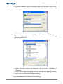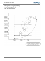
1
DVR100 Series Digital Video Recorder User’s Manual F34-100070-000A A1 DVR100 Series User’s Manual Caution and Preventive Tips Handle with care, do not drop the unit Mount the unit in an equipment rack or place it on a solid, stable surface Indoor use only. Do not place the unit in a humid, dusty, oily, or smoky site Do not place it in an area with poor ventilation or in an area close to fire or other sources of heat. Doing so may damage the unit as well as cause fire or an electric shock When cleaning is necessary, shut down the system and unplug the unit from the outlet before uncovering the top cover. Do not use liquid cleaners or aerosol cleaners. Use only a damp cloth for cleaning Always shut down the system prior connecting or disconnecting accessories, with the exception of USB devices This symbol intends to alert the user to the presence of important operating and maintenance (servicing) instructions in the literature accompanying the appliance. This symbol intends to alert the user to the presence of unprotected “Dangerous Voltage” within the product’s enclosure that may be strong enough to cause a risk of electric shock. 1 DVR100 Series User’s Manual Important Information Before proceeding, please read and observe all instructions and warnings in this manual. Retain this manual with the original bill of sale for future reference and, if necessary, warranty service. When unpacking your unit, check for missing or damaged items. If any item is missing, or if damage is evident, DO NOT INSTALL OR OPERATE THIS PRODUCT. Contact your dealer for assistance. Rack Mounting Consult with the supplier or manufacturer of your equipment rack for the proper hardware and procedure of mounting this product in a safe fashion. Avoid uneven loading or mechanical instability when rack-mounting units. Make sure that units are installed to get enough airflow for safe operation. The maximum temperature for rack-mounted units is 40 °C. Check product label for power supply requirements to assure that no overloading of supply circuits or over current protection occurs. Mains grounding must be reliable and uncompromised by any connections. 2 DVR100 Series User’s Manual Table of Content 1. Overview .....................................................................................................................11 2. System Setup..............................................................................................................12 2.1 Position the DVR ...............................................................................................12 2.2 Connect Devices to the DVR .............................................................................12 2.3 Rear Panel Connections....................................................................................13 3. General System Setup ...............................................................................................15 3.1 Front Panel Introduction ....................................................................................15 3.1.1 LED Definition ......................................................................................15 3.1.2 Function Keys.......................................................................................16 3.2 Enter OSD Setup Menu .....................................................................................18 3.2.1 User Management................................................................................18 3.3 Power Up / Shutdown the DVR..........................................................................19 3.3.1 HDD Auto Scan ....................................................................................21 3.4 System Date / Time Setting ...............................................................................22 3.4.1 Set Date / Time.....................................................................................22 3.4.2 Daylight Saving Time............................................................................23 3.4.3 Network Time Protocol Setup ...............................................................24 3.5 Record Schedule / Quality Setting .....................................................................25 3.5.1 Record Mode Setup .............................................................................25 3.5.2 Schedule Setup ....................................................................................26 3.5.3 Preset Record Configuration ................................................................26 3.5.4 Per Camera Configuration....................................................................27 3.5.5 Record Event Video Only .....................................................................27 3.5.6 ezRecord Setup....................................................................................28 3.5.7 Data Lifetime Setup..............................................................................29 3.5.8 Circular Recording................................................................................30 3.5.9 Audio Recording...................................................................................30 3.5.10 Purge Data ...........................................................................................30 3.6 Event Setting .....................................................................................................31 3.6.1 Internal Buzzer .....................................................................................31 3.6.2 Event Icon ............................................................................................31 3.6.3 Email Notice .........................................................................................32 3.6.4 Email Attachment .................................................................................32 3.6.5 Alert Notification Setup.........................................................................32 3.6.5.1 Alert Configuration Set ...........................................................32 3.6.5.2 Alert Notification .....................................................................32 3.6.5.3 Alert IP ...................................................................................33 3.6.5.4 Alert Port ................................................................................33 3 DVR100 Series User’s Manual 3.6.6 3.6.7 3.6.8 3.6.5.5 Alert Interval ...........................................................................33 Event Full Screen .................................................................................33 Event Duration......................................................................................33 Per Channel Config ..............................................................................33 3.6.8.1 Channel Select.......................................................................34 3.6.8.2 Video Loss Detect ..................................................................34 3.6.8.3 Motion Detect.........................................................................34 3.6.8.4 Detection Configuration .........................................................34 3.6.8.5 Alarm In..................................................................................35 3.6.8.6 Alarm Out ...............................................................................35 4. Basic Operation ..........................................................................................................36 4.1 View Live / Playback Video................................................................................36 4.1.1 Viewing Modes .....................................................................................36 4.1.2 Digital Zoom .........................................................................................37 4.1.3 View Live Cameras ..............................................................................37 4.1.4 View Recorded Video ...........................................................................37 4.2 Sequence ..........................................................................................................39 4.2.1 Sequence with Main Monitor ................................................................39 4.2.2 Sequence with Call Monitor..................................................................39 4.3 Search Recorded Video.....................................................................................40 4.3.1 Search by Time ....................................................................................40 4.3.2 Calendar Search ..................................................................................41 4.3.3 Search by Event ...................................................................................42 4.4 Video Export ......................................................................................................43 4.4.1 Export from OSD Setup Menu..............................................................43 4.4.1.1 Select the External Device ......................................................43 4.4.1.2 Select Video for Exporting.......................................................44 4.4.1.3 Digital Signature......................................................................45 4.4.1.4 Erase Disc...............................................................................45 4.4.2 Quick Video Export through Front Panel ..............................................46 4.4.2.1 ezBurn Introduction.................................................................46 4.4.2 Export Normal Video ............................................................................47 4.4.3 Export Event Video...............................................................................47 4.5 Dome Control.....................................................................................................48 4.5.1 Dome Connection.................................................................................48 4.5.2 Dome Protocol Setup ...........................................................................48 4.5.3 RS485 Setup ........................................................................................49 4.5.4 Dome Controlling Buttons ....................................................................49 4.5.5 Set Preset Points..................................................................................50 4.5.6 Preset Points ........................................................................................51 4 DVR100 Series User’s Manual 4.6 4.5.7 Run Dome Camera Tour.......................................................................51 System Log Exportation.....................................................................................52 5. Remote Monitoring Software.....................................................................................53 5.1 Remote Monitoring System Requirements ........................................................53 5.2 Installation of Software.......................................................................................54 5.2.1 Change Internet Settings......................................................................54 5.2.2 Install the Remote Monitoring Software................................................56 5.2.2.1 Login / Logout .........................................................................58 5.2.2.2 Software Upgrades .................................................................59 5.3 Basic Operation .................................................................................................59 5.3.1 View Live Video ....................................................................................59 5.3.1.1 Select Display Mode ...............................................................60 5.3.1.2 Operate Cameras with Dome Control .....................................60 5.3.2 Instant Recording .................................................................................61 5.3.2.1 Record Video Instantly ............................................................61 5.3.2.2 Playback Instant Recorded Video ...........................................61 5.3.3 Playback Video.....................................................................................62 5.3.3.1 Playback Remote Video..........................................................62 5.3.3.2 Playback Local *.drv Files .......................................................63 5.3.3.3 Playback Controls ...................................................................63 5.3.4 Verify Digital Signature .........................................................................64 5.3.5 Search from Event List .........................................................................64 5.3.6 Take a Snapshot...................................................................................65 5.3.7 Health Status ........................................................................................65 5.3.8 Remote Monitoring Software Troubleshooting......................................66 6. OSD Menu System Overview.....................................................................................67 6.1 Username and Password ..................................................................................67 6.2 Key Usage .........................................................................................................67 6.2.1 Key Usage in OSD Menu .....................................................................67 6.2.2 Key Usage in Virtual Keyboard.............................................................68 7. OSD System Setup .....................................................................................................70 7.1 System/Version Info...........................................................................................70 7.1.1 Model Name .........................................................................................70 7.1.2 Video System .......................................................................................70 7.1.3 Hardware..............................................................................................71 7.1.4 Software ...............................................................................................71 7.1.5 MAC Address 1 ....................................................................................71 7.1.6 Software Upgrade via Local Device .....................................................71 7.1.7 Software Upgrade Via Internet .............................................................72 7.2 Language...........................................................................................................72 5 DVR100 Series User’s Manual 7.3 7.4 7.5 7.6 7.7 6 Date/Time ..........................................................................................................72 7.3.1 Date / Time ...........................................................................................72 7.3.2 Time Zone ............................................................................................73 7.3.3 Date/Time Display ................................................................................73 7.3.4 Date Display Mode ...............................................................................73 7.3.5 Time Display Mode...............................................................................73 7.3.6 Daylight Saving Time Setup .................................................................74 7.3.6.1 Daylight Saving Time ..............................................................74 7.3.6.2 DST Start / End .......................................................................74 7.3.6.3 DST Bias.................................................................................74 7.3.7 Network Time Protocol Setup ...............................................................74 7.3.7.1 NTP Server .............................................................................74 7.3.7.2 Automatically Time Sync .........................................................75 7.3.7.3 Manually Time Sync................................................................75 Unit Name..........................................................................................................75 Show Unit Name................................................................................................75 User Management .............................................................................................75 7.6.1 Password Protection ............................................................................76 7.6.2 Account Setup ......................................................................................76 7.6.3 Authority Setup.....................................................................................76 7.6.4 Load Default Setting.............................................................................77 Network Setup ...................................................................................................77 7.7.1 LAN Select ...........................................................................................78 7.7.2 LAN Setup ............................................................................................78 7.7.2.1 DHCP......................................................................................78 7.7.2.2 IP ............................................................................................79 7.7.2.3 Netmask..................................................................................79 7.7.2.4 Gateway..................................................................................79 7.7.2.5 DNS ........................................................................................79 7.7.2.6 PPPoE Account.......................................................................79 7.7.2.7 PPPoE Password....................................................................80 7.7.2.8 PPPoE Max Idle......................................................................80 7.7.2.9 Connect At Booting .................................................................80 7.7.2.10 Network Restart ......................................................................80 7.7.3 Trigger Port ..........................................................................................81 7.7.4 Email Address ......................................................................................81 7.7.5 SMTP Setup .........................................................................................81 7.7.5.1 Email via SMTP ......................................................................81 7.7.5.2 SMTP Server ..........................................................................82 7.7.5.3 SMTP Port ..............................................................................82 DVR100 Series User’s Manual 7.8 7.9 7.7.5.4 SMTP Account ........................................................................82 7.7.5.5 SMTP Password .....................................................................83 7.7.5.6 Use SSL Connection...............................................................83 7.7.6 DDNS Setup.........................................................................................83 7.7.6.1 Enable DDNS..........................................................................83 7.7.6.2 Host Name ..............................................................................84 7.7.6.3 DDNS Port ..............................................................................84 7.7.6.4 Submit/ Update .......................................................................84 7.7.6.5 ezDDNS ..................................................................................85 RS485 Setup .....................................................................................................85 7.8.1 Unit ID ..................................................................................................85 7.8.2 Baud Rate ............................................................................................85 7.8.3 Bits .......................................................................................................85 7.8.4 Stop ......................................................................................................86 7.8.5 Parity ....................................................................................................86 Audio Output/Key Beep .....................................................................................86 7.9.1 Audio Output ........................................................................................86 7.9.2 Key Beep..............................................................................................86 7.9.3 Split Mode Audio...................................................................................86 8. Monitor Setup .............................................................................................................88 8.1 Show Camera Title ............................................................................................88 8.2 OSD Transparency ............................................................................................88 8.3 VGA Resolution .................................................................................................88 8.4 Show Color Bar..................................................................................................88 9. Camera Setup .............................................................................................................89 9.1 Analog Camera..................................................................................................89 9.1.1 9.1.2 9.1.3 9.1.4 9.1.5 9.1.6 9.1.7 9.1.8 9.1.9 Analog Camera Select .........................................................................89 Dome Protocol......................................................................................89 Dome ID ...............................................................................................89 Camera Title .........................................................................................90 Covert...................................................................................................90 Brightness ............................................................................................90 Contrast................................................................................................90 Saturation .............................................................................................91 Hue.......................................................................................................91 10. Record Setup ..............................................................................................................92 10.1 Record Mode Setup...........................................................................................92 10.1.1 Record Resolution................................................................................92 10.1.2 Record Format .....................................................................................93 10.1.3 Max Rec. PPS ......................................................................................93 7 DVR100 Series User’s Manual 10.2 10.3 10.4 10.5 10.6 10.7 10.8 10.9 10.1.4 CBR/VBR .............................................................................................93 Schedule Setup .................................................................................................93 10.2.1 Day / Night Time Start / End .................................................................94 10.2.2 Weekend Schedule ..............................................................................94 10.2.3 Weekend Start / End ............................................................................94 Preset Record Configuration..............................................................................94 Per Camera Config ............................................................................................95 10.4.1 Camera Select......................................................................................95 10.4.2 Normal PPS..........................................................................................96 10.4.3 Normal Qlty ..........................................................................................96 10.4.4 Event Max PPS ....................................................................................96 10.4.5 Event Qlty.............................................................................................96 10.4.6 Event Active..........................................................................................96 ezRecord Setup .................................................................................................96 Data Lifetime Setup ...........................................................................................97 10.6.1 Data Lifetime Mode ..............................................................................98 10.6.2 Data Lifetime ........................................................................................98 10.6.3 Data Lifetime By Day............................................................................98 10.6.4 Data Lifetime By Channel.....................................................................98 Circular Recording .............................................................................................99 Audio Recording ................................................................................................99 Purge Data.........................................................................................................99 10.9.1 Purge All Data ......................................................................................99 10.9.2 Purge All Event Data ............................................................................99 10.9.3 Purge Event Before ............................................................................100 10.9.4 Start To Purge.....................................................................................100 11. Sequence Setup .......................................................................................................101 11.1 Main / Call Monitor Dwell .................................................................................101 11.2 Main / Call Monitor Schedule ...........................................................................101 12. Event Setup...............................................................................................................103 12.1 Internal Buzzer.................................................................................................103 12.2 Event Icon........................................................................................................103 12.3 Email Notice.....................................................................................................103 12.4 Email Attachment.............................................................................................104 12.5 Alert Notification Setup ....................................................................................104 12.5.1 Alert Configuration Set .......................................................................104 12.5.2 Alert Notification .................................................................................104 12.5.3 Alert IP ...............................................................................................105 12.5.4 Alert Port ............................................................................................105 12.5.5 Alive Interval.......................................................................................105 8 DVR100 Series User’s Manual 12.6 Event Full Screen ............................................................................................105 12.7 Event Duration .................................................................................................105 12.8 Per Channel Config .........................................................................................105 12.8.1 Channel Select ...................................................................................106 12.8.2 Video Loss Detect ..............................................................................106 12.8.3 Motion Detect .....................................................................................106 12.8.4 Detection Configuration......................................................................106 12.8.4.1 Detected Area Setup......................................................106 12.8.4.2 Sensitivity.......................................................................107 12.8.4.3 Block Threshold .............................................................107 12.8.5 Alarm In..............................................................................................107 12.8.6 Alarm Out ...........................................................................................107 13. Database Setup.........................................................................................................109 13.1 Total / Free Size...............................................................................................109 13.2 Avail. Rec Time................................................................................................109 13.3 Internal Disks ...................................................................................................109 13.4 Repair On Power Loss..................................................................................... 110 14. Configuration............................................................................................................ 111 14.1 Load Factory Default ....................................................................................... 111 14.2 Import Configuration ........................................................................................ 111 14.3 Export Configuration ........................................................................................ 112 14.3.1 Copy Destination ................................................................................ 112 14.3.2 Configuration Name ........................................................................... 112 14.3.3 Begin Export....................................................................................... 112 14.4 System Log...................................................................................................... 113 14.5 Operation Log .................................................................................................. 113 15. Export ........................................................................................................................114 15.1 Select Device................................................................................................... 114 15.2 Select Channel ................................................................................................ 115 15.3 From / To Time................................................................................................. 115 15.4 Select Events................................................................................................... 115 15.5 Data Type ........................................................................................................ 115 15.6 Export Format .................................................................................................. 116 15.7 Digital Signature .............................................................................................. 116 15.8 Erase Disc ....................................................................................................... 116 15.9 Begin Export .................................................................................................... 117 16. Shutdown ..................................................................................................................118 16.1 Power Off......................................................................................................... 118 16.2 Reboot ............................................................................................................. 118 16.3 Power Key Privilege......................................................................................... 118 9 DVR100 Series User’s Manual Appendix A: D-Sub Lead Instruction ...........................................................................120 Appendix B: Recommended HDDs ..............................................................................122 Appendix C: Remote Controller ...................................................................................123 Appendix D: Setup a DVR behind a Router .................................................................125 Appendix E: ezRecord Diagram Samples....................................................................128 Appendix F: Record Duration .......................................................................................131 Appendix G: DVRPlayer ................................................................................................134 Appendix H: USB Mouse Operation .............................................................................139 Appendix I: HDD Copy Tool (EXT2IFS) ........................................................................141 10 DVR100 Series User’s Manual 1. Overview DVR100 Series is an integrated digital video recorder that combines the features of a time-lapse audio / video recorder, a multiplexer, and a video server to create a single security solution. Its outstanding quadplex operation enables users to view live video, search and playback any recorded video by date/time or event, and remotely monitor the unit via internet on PC, MEANWHILE the recording of the DVR unit is ongoing simultaneously. DVR100 Series provides the latest H.264 compression mode. Moreover, a marvelous implementation is the brand-new experience of Graphical User Interface (GUI) that optimizes the monitoring controls of the unit. With the quality displaying features, DVR100 Series is in the meantime enhanced to support Full HD 1080p output. DVR100 Series is pre-installed with remote viewing and configuration software, which is a Web-browser plug-in allowing users to view live or recorded video images, and enables remote configuration. The remote software is stored in DVR100 Series and deployed over a LAN, WAN or Internet connection to remote Windows-based computers. This simplifies the installation and maintenance of the software components so all remote users are using the same software coming from the unit. 11 DVR100 Series User’s Manual 2. System Setup The notices and introduction on system installation will be described particularly in this chapter. Please follow the description to operate the unit. In order to prevent the unit from data loss and system damage that caused by a sudden power fluctuation, use of an Uninterruptible Power Supply (UPS) is highly recommended 2.1 Position the DVR First, note to position / mount the DVR in a proper place and be sure to power off the unit before making any connections. The placed location should avoid hindering or blocking the unit from airflow. Enough airflow is needed to protect the unit from overheating. The maximum allowable temperature of operating environment is 40°C. The unit utilizes heat-conducting techniques to transfer internal heat to the case, especially to the bottom side of the unit. NOTE: Be sure the rubber feet are not removed, and always leave a space for air ventilation on the unit’s bottom side. 2.2 Connect Devices to the DVR This section lists some important notices that should be read before making any connection to the DVR. Connecting Required Devices Before power up the unit, cameras and a monitor should be connected to the unit for basic operation. If needed, connect a call monitor for displaying full screen video of all installed cameras in sequence. Connecting Short-term Device If any short-term devices shall be installed to the DVR as parts of the unit system, such as USB ThumbDrive® or any USB devices, etc, make sure those devices are connected only after the unit is powered up. The reason is because the DVR can recognize the external devices only after the powerup process is done completely. 12 DVR100 Series User’s Manual 2.3 Rear Panel Connections There are various connectors on the rear panel for the DVR installations. The following shows the detailed description of each connector. Main Monitor (BNC/ VGA/ Digital Output) The DVR supports three different types of main monitor: BNC, VGA, or Digital Output. The main monitor displays live image and playback recorded video in full-screen or split-window format. Digital Output connector is optional. Call Monitor The BNC call monitor connector allows users to connect the DVR with an optional call monitor. The call monitor is used to display full screen video of all installed cameras in sequence. Video In A group of BNC connectors is offered for video input from installed cameras. The number of connectors equals the number of channels. Note: The DVR will detect video source of CH1 and automatically adjust the system to NTSC or PAL system. Audio Out – Main & Call (4CH & 8CH models only) Main & Call Audio Out RCA connectors are provided for connecting the DVR to audio output devices (e.g. amplified speakers). “MAIN AUDIO OUT” will output audio from the main monitor, whereas “CALL AUDIO” will output audio form the call monitor. Audio In/Out (16CH models only) 16CH models provide audio in/out connection via a D-Sub connector. Users can connect audio source devices for each channel and audio output devices for Main/Call monitors. Refer to Setup Guide for detailed pin definitions for different models. 13 DVR100 Series User’s Manual Alarm I/O, RS-485 & Audio In A D-Sub connector is provided to offer users the flexibility to connect the DVR to Alarm I/O, RS-485 and Audio In devices. Refer to Setup Guide for detailed pin definitions for different models. LAN Connector (RJ-45) The DVR is capable of networking. Once the unit is connected to the LAN network, users can remotely access the unit through the remote software on a PC. USB Connector (x1) There is one USB port provided to allow users to connect USB devices, such as USB mouse or USB storage. Power Jack The DVR has a 12V DC power connection jack. Please connect the power adapter shipped with the unit. 14 DVR100 Series User’s Manual 3. General System Setup Before operating the DVR, some general configuration should be setup first. The following subsections will introduce function keys on the front panel and general configuration of the DVR. The regular displayed OSD information and its displayed positions are shown as following figure. Title of the channel will be displayed on the topleft corner of the window, either in full screen mode or in multiple channel mode. The current operation status and date/time information will be displayed in the status bar at the bottom-left corner of the screen. Move the cursor to any status icon and its description will be displayed. Refer to the Setup Guide for a list of status bar icons and their descriptions. Ch1 2011/03/09 PM 04:31:22 3.1 Front Panel Introduction The front panel controls enable users to control the unit and preset the programmable functions. 3.1.1 LED Definition The LEDs on the front panel of the DVR are described as follow. REC LED The LED blinks while the DVR is recording. Alarm LED The LED lights up when an alarm is triggered. Network LED The LED lights up when the DVR is connected to a network and blinks when the data is being transferred. 15 DVR100 Series User’s Manual 3.1.2 Function Keys This section describes the functional keys on the front panel of the DVR. Refer to the Setup Guide for the graphical illustration of functional keys. Power Key When the quick shutdown function is enabled, press and hold this key to quick shutdown the DVR. Refer to section Power Up / Shutdown the DVR for more information about the setting of quick shutdown function. CHANNEL In both Live and Playback modes, press the CHANNEL key to view the corresponding video in full screen. The number of the CHANNEL keys corresponds to the number of cameras supported by the unit. In Dome Control mode, press “1” to access the Set/Go Preset menu. In OSD number keyboard, press keys “1” ~ “9” to input number 1~9, and press key “10” to input number 0. DOME(PTZ) Press the key to enter dome control mode. Please refer to section Dome Control for detailed controlling operation. MODE Press repeatedly to select for preferred monitor display format. The available viewing modes includes: full-screen, 4-window (2×2), 9-window (3×3) and 16-window (4×4). Refer to section Viewing Modes for detailed information. SEQ (Sequence) Press to start automatic sequence display of video from all installed cameras. MENU Press this key to enter the OSD setup menu. COPY In Playback mode, press COPY to select the start and end time of the export video. Refer to section Video Export for detailed information. CALL In Live mode, press this button to enter call monitor control mode. PLAY/STOP 16 DVR100 Series User’s Manual Press this key to switch between live image and playback video. NOTE: According to record setting, part of the latest video cannot be played back because the video is still saved in the buffer. FREEZE Press FREEZE while viewing live image, the live video will be frozen. The date / time information shown on the monitor will continue updating. Press FREEZE again to return to live mode. Press FREEZE while playing the recorded video, the playback video will be paused. Press LEFT / RIGHT to move the recorded video reverse / forward by single step. Press FREEZE again to continue playing video. SEARCH In both Playback and Live mode, press SEARCH to enter the Search menu to search and playback recorded video by date/time or events. Press twice to instantly playback the latest recorded videos. ESC Press to cancel or exit from certain mode or OSD setup menu without changing the settings made previously. When password protection is switched off, press ESC for five seconds to lock up the system. Press ESC for five seconds again to unlock. NOTE: Enter the OSD menu and go to <System Setup> <User Management> to enable or disable the password protection. Direction Keys In Zoom mode, press these keys to move to desired directions. In the OSD setup menu, the LEFT/ RIGHT keys are used to move the cursor to previous or next fields. To change the value in the selected field, press UP/ DOWN keys. ENTER / ZOOM In OSD setup menu or selection interface, press this key to make the selection or save settings. In live full screen view mode, press this key to view a 2× zoom image. Press it again to exit Zoom mode. 17 DVR100 Series User’s Manual 3.2 Enter OSD Setup Menu The configuration of the DVR can be customized by entering the intuitive Graphical User Interface (GUI) OSD setup menu. Collaborating with a USB mouse, setting up the DVR can be easy as operating on a PC. Press MENU and select an account to login. The next step is to enter a corresponding password. The preset password for the administrator account “admin” is “1234”. NOTE: It is strongly suggested to change the preset password to prevent unauthorized access to the unit. An icon displayed at the status bar will show the authority level of the account. Under logout condition, the “Guest” icon will be displayed. When an account is logged in, its authority level number (1~8) will be shown. Before completely logout, other functions can also be accessed without having to login again. There are two ways to logout: manually logout by pressing ESC key at Live mode, or auto logout when keys are not pressed for 5 minutes at Live/ Menu mode. 3.2.1 User Management The DVR provides the option to create up to seven sets of usernames and passwords with customized authority, excluding the preset “admin” account. From the Main Menu, select <System Setup> <User Management> and the menu is as the following: User Management Password Protection Account Setup Authority Setup Load Default Setting On No Password Protection Select <On> to request for username and password for accessing functions listed in Authority Setup menu, or select <Off> to allow free access. 18 DVR100 Series User’s Manual Account Setup Setup customized account, password, and privilege level in this menu. The account is case sensitive. The privilege level rank from levels 1~8, which level 8 has the highest privilege. Alternatively, select <Disable> to stop using the account. NOTE: The username and authority level of the preset “admin” account cannot be changed. Authority Setup Setup the allowed authority level for accessing the functions listed in this menu. The items include: Playback/Search, Covert Camera, Dome Control, Live Operation, Call Control, Export Data, Menu Access, System Setup, Monitor Setup, Camera Setup, Record Setup, Sequence Setup, Event Setup, Database Setup, Configuration and Shutdown. In accordance with users’ privilege level defined in <Account Setup>, the authority level here also ranks from levels 1~8, with level 8 as the highest level. Users will be able to access any function that is set to their equivalent level or lower. Alternatively, select <DISABLE> to allow free access. NOTE: The “Menu Access” cannot be set to <DISABLE>. When the account does not have authority to access certain functions, an error message will be displayed on the screen. Load Default Setting Select <Yes> to load the default setting. 3.3 Power Up / Shutdown the DVR If the DVR must be shutdown for any reason, please use the proper shut down and power up procedures to avoid damaging the DVR. Power Up the Unit Simply plug in the power adapter that came with the package and the DVR will start to boot. The color bar and system checking information will be shown on the monitor and then disappear when the unit has been completely powered up. 19 DVR100 Series User’s Manual Restart / Shutdown the Unit Press MENU and input the username and password that has sufficient authority to access the OSD setup menu. Select <Shutdown> in Main Menu and press ENTER to enter the Shutdown menu, which displays as follows. Shutdown Power Off Reboot Power Key Privilege Auth <Power Off> Select this item to shut down the unit. Do not remove the power during shut down until the message “You can safely turn off DVR now!” displays. <Reboot> Select this item to reboot the unit. The color bar and system checking information are displayed on the monitor until the unit is completely restarted. <Power Key Privilege> According to the setting of this item, users are able to quick shutdown the DVR via long pressing the Power Key. This item defines the action of the power key. The options are <Auth>, <Confirm>, <Direct>, and <Disable>. The following explains each option. Auth: This will ask users to login with an authorized account, when Password Protection function is enabled. If Password Protection function is disabled, the action will be the same as the next option <Confirm>. Confirm: When this option is selected, a confirmation message will be shown after long pressed the Power Key. Users can confirm or cancel the quick shutdown function. Direct: For users who wish to enable the quick shutdown function without any confirmation or login process, select this option and the DVR will automatically shutdown after long pressed the Power Key. Disable: Select this option to disable the quick shutdown function. 20 DVR100 Series User’s Manual 3.3.1 HDD Auto Scan When the DVR is powering on, HDD auto scan will be initiated if there was previously an unusual power loss or file system error. If by any chance auto scan failed, the HDD will need to be formatted. NOTE: If users wish to disable the auto scan function, enter the OSD setup menu via an authorized account and access <Database Setup> to set <Repair On Power Loss> to <Off>. Read the following troubleshooting to finish the auto scanning process. Skip Auto Scan: During the scanning process, users can press any key to skip the process. Time Expired: When the scanning process took more than predetermined time (3hrs for 1TB HDD, 6hrs for 2TB HDD, etc), the scanning process is treated as failed and will be automatically terminated. The DVR will reboot. Format HDD: If the scanning process is failed, users will be prompted to confirm format of the HDD with error. When users confirmed to format the HDD with error, login of an authorized account is required if password protection is enabled. If users select cancel or do not respond within 5 minutes, the HDD with error will be marked as a NG HDD. A NG HDD will not be counted as a part of the DVR’s database. It will just stay there doing nothing. Recover NG HDD: Enter the OSD setup menu via an authorized account and access <Database Setup>. Then select <Internal Disks> and find the NG HDD from the list. Under <Action> column, first select <Format> to format the NG HDD. Then select <Add> to add the formatted HDD to the DVR’s database. NOTE: The above actions will be recorded in the system log data. 21 DVR100 Series User’s Manual 3.4 System Date / Time Setting Users can set the current date, time and other OSD parameters in Date/Time menu (under System Setup menu). The login account should have authority to access the System Setup menu. In OSD setup menu, select <System Setup> and press ENTER, then select <Date/Time> to access the Date/Time menu; the menu displays as follows. Date/Time Date Time Time Zone Date/Time Display Date Display Mode Time Display Mode Daylight Saving Time Setup Network Time Protocol Setup 3.4.1 2011/02/21 PM 10:39:26 OFF ON Y/M/D 12 HR Set Date / Time Set Date / Time Select <Date> / <Time> and press ENTER to adjust the settings. LEFT / RIGHT keys are used to move the cursor to previous or next field, ENTER is for selecting, and UP / DOWN are used to change the value in the selected field. NOTE: The new date / time setting applies to record new video. The date and time of previously recorded video will not be changed. NOTE: If time settings have to be changed in any case, it is strongly recommended to format the HDDs to avoid database corruption. Date / Time Display Select <ON> or <OFF> to setup whether to display date/time information on the screen. Press ENTER and use the UP / DOWN keys to change the setting. Date Display Mode This function allows users to set the OSD display type of the date. There are three options to select from: <Y/M/D>, <M/D/Y> or <D/M/Y>. “Y” represents “Year”, “M” represents “Month” and “D” represents “Day”. Move to the item and press ENTER, the option starts blinking. Use UP / 22 DVR100 Series User’s Manual DOWN keys to change the setting. Time Display Mode Users can set the time format to <12 HR> or <24 HR>. Use the UP / DOWN keys to change the format. 3.4.2 Daylight Saving Time Daylight Saving Time The item is for those people who live in certain regions to observe Daylight Saving Time. Select <ON> to enable, or <OFF> to disable the function. If the function is disabled, the DST Start / End time and DST Bias will be grayed out and cannot be accessed. NOTE: If this function is enabled, the date/ time information will be shown on the screen with a DST icon when playing back recorded video or searching video in the event list. “S” indicates summer time and “W” indicates wintertime. DST Start / End The items are used to program the daylight saving duration. Use LEFT / RIGHT keys to move the cursor to the next or previous field, UP / DOWN to change the settings in the selected field. DST Bias The item allows users to set the amount of time to move forward from the standard time for daylight saving time. The available options are in minutes. 23 DVR100 Series User’s Manual 3.4.3 Network Time Protocol Setup Time Zone Select <Time Zone> to setup the time zone. To find out the correct local time zone, please visit www.greenwichmeantime.com or refer to below figure. NOTE: The <Time Zone> must be set to the correct local time zone or the <Network Time Protocol Setup> will not be accessible. Network Time Protocol Setup After setup the time zone, <Network Time Protocol Setup> will be accessible. Select <NTP Server> to setup the time server. The default time server is time.nist.gov, but the users can change to any other time server if preferred. A list of IP addresses of the time servers is listed below. 129.6.15.28 132.163.4.102 192.43.244.18 206.246.118.250 207.200.81.113 129.6.15.29 132.163.4.103 131.107.1.10 208.184.49.9 64.236.96.53 132.163.4.101 128.138.140.44 69.25.96.13 64.125.78.85 68.216.79.113 After the time server is set, set <Manually Time Sync> to <Yes> to sync the time. The time sync can also be updated periodically. Set <Automatically Time Sync> to <On>, and the time will be automatically synced once an hour. 24 DVR100 Series User’s Manual 3.5 Record Schedule / Quality Setting The Record Setup menu allows users to set recording quality, recording schedules, and other recording parameters. Login with a proper account to access Record Setup menu. In the Main menu, move the cursor to <Record Setup> and press ENTER; the following menu is displayed. Record Setup Record Mode Setup Schedule Setup Preset Config Per Camera Config ezRecord Setup Data Lifetime Setup Circular Recording Audio Recording Purge Data 3.5.1 Best Quality On On Record Mode Setup The Record Mode Setup menu allows users to setup record resolution, etc. The relative record settings, such as preset configuration, will follow the record mode setting. The menu is displayed as the following. Record Mode Setup Record Resolution Record Format Max Rec. PPS CBR/VBR 720*240 H264 240 CBR Select record resolution of the video from 720*480, 720*240, and 352*240 for NTSC systems. If the video system is PAL, the options will be 720*576, 720*288, and 352*288. Record Format of the video is H.264. It is “read-only”. Max Rec. PPS will be changed automatically according to the record resolution selected. Set the recording bit rate as CBR (Constant Bit Rate) or VBR (Variable Bit Rate). It is strongly suggested to use VBR encoding when reliable video quality is the top priority. 25 DVR100 Series User’s Manual NOTE: Since a VBR file does not have a fixed size, the HDD space usage cannot be calculated and thus ezRecord function is not supported for VBR mode. Therefore, if ezRecord is selected as the preset record configuration, the option of this menu item will automatically be set as <CBR>. 3.5.2 Schedule Setup The Schedule Setup is used to set the day and night time, or weekend recording schedule. Select <Schedule Setup> from the Record Setup menu and press ENTER; the following menu is displayed. Schedule Setup Day Time Start Day Time End Night Time Start Night Time End Weekend Schedule Weekend Start Weekend End AM 06:00 PM 06:00 PM 06:00 AM 06:00 On Fri PM 06:00 Mon AM 06:00 Make appropriate changes of the start time of Day and Night Time using Direction keys. Press ENTER to confirm the settings or ESC to cancel. If a weekend record is required, select <On> to enable the Weekend Schedule in advance and then set the Weekend Start/End time. Press ESC to return to previous page. 3.5.3 Preset Record Configuration The <Preset Config> is used to select the preset recording quality and frame rate. In normal circumstances, it is strongly recommended to set the preset configuration as <Best Quality>. Below table shows the PPS and picture size under <Best Quality> in Half-D1 mode. Please refer to OSD Setup Manual, section Preset Record Configuration for more detailed information. Halfl-D1 mode (NTSC: 720*240@240PPS; PAL: 720*288@200PPS) Normal PPS Normal Size Event PPS Event Size 15 NTSC 30 NTSC 10 KB / PIC 10 KB / PIC (12.5 PAL) (25 PAL) 26 DVR100 Series User’s Manual 3.5.4 Per Camera Configuration This function is used to set the Day / Night / Weekend PPS (Picture per Second) and Quality for each channel. The Preset Configuration must be set to <OFF> for accessing these schedules. The menu is displayed as below (Record Mode: 720*240@240PPS in NTSC / 720*288@200PPS in PAL). Per Camera Config Cameral Select Normal PPS Normal Size Event Max PPS Event Size Event Active Day 15 Mid 30 Best Both Night 15 Mid 30 Best Both CH01 Weekend 15 Mid 30 Best Both Firstly, select a Camera for setting its record configuration. The image and recording settings from the selected camera will be displayed on the screen. Move the cursor using Direction keys and press ENTER to select an item. Change the value using UP / DOWN keys. Press ENTER to confirm the settings or ESC to abort. Press ESC to return to Record Setup menu. Please note that the total normal PPS for all channels cannot exceed 240 NTSC (720*240@240PPS) / 200 PAL (720*288@200PPS). To increase one channel’s PPS, you may have to reduce others’ first. Event PPS is not restricted to this rule, since a smart event scheduler will handle the total PPS with a correct weighting. 3.5.5 Record Event Video Only If the DVR shall start recording only when alarms are triggered, follow the steps below: Enter the OSD setup menu with correct password. In the OSD setup menu, select <Record Setup> menu. Move the cursor to the item <Preset Config>, and select <Event only>. Refer to OSD Setup Manual, section Preset Record Configuration for more detailed information. 27 DVR100 Series User’s Manual 3.5.6 ezRecord Setup This item aims to ease the complicated record settings, and to make the setup much easier. Note that the item can be reached only when <ezRecord> is selected as the option for <Preset Config>. Select <ezRecord Setup> from <Record Setup> and press ENTER, the submenu appears as below figure: ezRecord Setup How Many Days To Record Daytime Record Night Record Weekend Record Average Normal PPS Average Normal Quality 7 Days Yes Yes Yes 15 Best Follow these steps to Setup ezRecord: Select <How Many Days To Record> and press ENTER, then press UP/DOWN to choose an option. The average normal PPS & Quality will be adjusted automatically. The maximum of days depends of the size of the installed HDD. In other words, the larger the size of the HDD installed, the more days the unit can record. Move to <Daytime Record> and press ENTER. This item will determine whether the DVR will record during daytime. If yes, use UP/DOWN to select <Yes> as to enable daytime recording; or select <No> to disable. Repeat the same procedures through the 3rd and 4th item, respectively. Note that <Weekend Record> will be inaccessible if <Weekend Schedule> in <Schedule Setup> is set to <No>. Select <Average Normal PPS> and press ENTER, then press UP/DOWN to make a choice. The <How Many Days To Record> will be computed automatically. Select <Average Normal Quality> and press ENTER, then press UP/DOWN to make a choice. The <How Many Days To Record> will be computed automatically. NOTE: The current number of connected cameras will affect the recording quality automatically calculated through the <ezRecord Setup>. Therefore, once the number of connected cameras is changed, the <ezRecord Setup> should be reset. 28 DVR100 Series User’s Manual 3.5.7 Data Lifetime Setup Data Lifetime indicates the duration that a video is saved and recallable in the HDD. Only those video recorded within Data Lifetime can be displayed on the screen and played back. The video exceeded Data Lifetime will be hidden and cannot be retrieved for playback. Data Lifetime Setup Data Lifetime Mode Data Lifetime Data Lifetime By Day Data Lifetime By Channel General 0 Days NOTE: To playback a video exceeding the data lifetime, please extend the duration until the recording data / time of the video is included. Data Lifetime Mode This item allows the user to choose preferred data lifetime mode. There are three types of data lifetime mode: General, By Day, and By Channel. When a specific mode is selected, further settings of the other two items below will be grayed out and cannot be accessed. Data Lifetime When data lifetime mode is set as <General>, this item will be accessible. Press ENTER to select this item and press UP / DOWN keys to set the data lifetime. The value ranges from <1> to <365> days. Alternatively, select <0> to disable this function. Data Lifetime By Day When data lifetime mode is set as <By Day>, this item will be accessible. Enter this menu and users can setup data lifetime of each weekday independently. The value ranges from <1> to <365> days. Alternatively, select <0> to disable this function. Data Lifetime By Channel When data lifetime mode is set as <By Channel>, this item will be accessible. Enter this menu and users can setup data lifetime of each channel independently. The value ranges from <1> to <365> days. Alternatively, select <0> to disable this function. 29 DVR100 Series User’s Manual 3.5.8 Circular Recording Users can choose to record video in circular mode or in linear mode. If circular mode is selected, the DVR will stores new video into the HDD spaces while overwrite the oldest recorded video. Alternatively, if linear mode is selected, the DVR will stop recording when the HDD is full. The percentage of HDD usage will be displayed at the status bar. Moreover, an “ALMOST FULL” icon will show up at the status bar when HDD usage reached 98%. In the mean time, an internal buzzer will start beeping. From the Record Setup menu, move the cursor to <Circular Recording> and press ENTER, then select <On> / <Off> using UP / DOWN keys. 3.5.9 Audio Recording When an audio source device is connected, it will be automatically set to <On>, audio input is recorded and saved with the video. When no audio source device is connected, it will be automatically set to <Off>. 3.5.10 Purge Data This item is used to delete the Normal or Event recording video. In Record Setup menu, move the cursor to <Purge Data> and press ENTER; the Purge Data menu is displayed. Purge Data Purge All Data Purge All Event Data Purge Event Before Start To Purge No No 2000/01/01 No Purge All Data The item is used to delete all recorded video from the database. Set this item to <Yes using UP / DOWN keys, and start the deletion by setting <Start To Purge> to <Yes>. Purge All Event Data The item is used to delete all event video from database(s). Using UP / DOWN keys to select <Yes> and start the deletion by setting <Start To Purge> to <Yes>. 30 DVR100 Series User’s Manual Purge Event Before The item is used to delete event video before a specific date. Use LEFT / RIGHT keys to move the cursor to next or previous field, ENTER to select the item and UP / DOWN to adjust the value. Start To Purge After the video or data to be deleted are selected, set this item to <Yes> to start the deletion or choose <No> to cancel. 3.6 Event Setting This menu allows users to determine the DVR’s behavior in response to alarm events. In the Main menu, move the cursor to <Event Setup> and press ENTER. The following menu is displayed. Items in the Event Setup menu are described in the following subsections. Event Setup Internal Buzzer Event Icon Email Notice Email Attachment Alert Notification Setup Event Full Screen Event Duration Per Channel Config 3.6.1 On On Off Off None 20 Sec Internal Buzzer This item allows users to enable / disable internal buzzer of the DVR. If <On> is selected, the buzzer is activated in response to alarm events. If <Off> is selected, the buzzer is not activated. 3.6.2 Event Icon This item enables (On) / disables (Off) the display of event icons on the monitor when alarm events occur. The event icons are represented by a character according to the event types respectively. Refer to the following table for association of event icons and event types. Event Icon A M L Event Type Alarm in event Motion detection event Video loss event 31 DVR100 Series User’s Manual 3.6.3 Email Notice The item enables (On) / disables (Off) the Email notification of an event. When an alarm event is triggered and <Email Notice> is enabled, an email regarding the alarm event will be sent. NOTE: In order to send an event notification email successfully, ensure that the DVR is connecting to the internet. 3.6.4 Email Attachment The function allows the DVR to send out a brief AVI video regarding the event. The number of the attached AVI video will be equivalent to the number of cameras connected to the DVR. For example, if the DVR has been connected with 8 cameras, then 8 videos will be attached to the notice email. The total size of the video will be about 2 MB. Select <On> to enable this function; or <Off> to disable it. NOTE: The video clips of the Email Attachment will ONLY be in *.avi format. Please download the Divx Player from www.divx.com to playback the *.avi files. 3.6.5 Alert Notification Setup This function allows users to send alert notifications to the CMS software which had been installed to users’ computer. For further setup instruction at the CMS side, please refer to the CMS user’s manual. Alert Notification Setup Alert Configuration Set Alert Notification Alert IP Alert Port Alive Interval 3.6.5.1 1 OFF 0.0.0.0 9999 120 Sec Alert Configuration Set <Alert Configuration Set> provides 3 combinations of Alert Notification, IP, Port, and Interval. 3.6.5.2 Alert Notification 4 options are included in this item: <OFF>, <Event>, <Alive>, and <Both>. 32 DVR100 Series User’s Manual <OFF>: The Alert Notification is turned off. <Event>: When the alarm is triggered, the DVR will send an alert message to the CMS. <Alive>: The DVR will send an alive message to the CMS every N second just to show you that the connection between the DVR and CMS is in effect. The time interval N can be adjusted in <Alive Interval>. <Both>: This enables the DVR to send both Event and Alive alert messages to the CMS. 3.6.5.3 Alert IP The Alert IP must match the IP address of the computer installed the CMS. 3.6.5.4 Alert Port The ports for DVR and the CMS Alert MUST be the same. 3.6.5.5 Alert Interval Users can define the time interval (1 to 255 seconds) between each alive message. 3.6.6 Event Full Screen This function allows the DVR to display the alarm channel in full screen size when an alarm is triggered. Select <None> to disable this function; select <Main> to display the alarm channel on Main Monitor when an alarm is triggered; select <Call> to display the alarm channel on Call Monitor; and select <Both> to display the alarm channel on both Main Monitor and Call Monitor. 3.6.7 Event Duration This item determines the duration of the buzzer and Alarm Out relay function after an alarm is triggered. The available event duration range is from 5 second to 999 seconds. 3.6.8 Per Channel Config This menu is used to configure the <Video Loss Detect>, <Motion Detect>, <Alarm In> and <Alarm Out> settings for each channel. The menu is displayed as below. 33 DVR100 Series User’s Manual Per Channel Config Channel Select Video Loss Detect Motion Detect Detection Config Alarm In Alarm Out 3.6.8.1 CH01 Off Off OFF ON Channel Select The item is used to select a desired channel for setting the parameters. Move the cursor to <Channel Select> and press ENTER, then select a channel using UP / DOWN keys. Press ENTER again to confirm the selection. 3.6.8.2 Video Loss Detect This item allows users to enable or disable Video Loss as an alarm event. Select <On> to enable Video Loss alarm events, or <Off> to disable. 3.6.8.3 Motion Detect This item allows users to enable or disable motion detection function of the DVR. Select <On> to enable Motion Detect alarm events, or <Off> to disable. If motion detection function is enabled, it is required to define motion detection parameters such as detection area and sensitivity settings in <Detection Config>. 3.6.8.4 Detection Configuration If motion detection function is enabled, it is required to define the motion detection parameters such as detection area and sensitivity settings. Select a channel for setting the parameters, move the cursor to <Detection Config> and press ENTER. The Detection Configuration menu displays as follows. Detection Config Detected Area Setup Sensitivity Block Threshold 88% 4 Detected Area Setup After selected this item, the detected area is displayed as follows. The detection area consists of 192 (16×12) detection grids. 34 DVR100 Series User’s Manual Use the Direction keys to move the cursor and press ENTER to select or deselect a grid. Press MODE to select all of the grids for detection; press MODE again to de-select all of the grids. Sensitivity This item is used to set the sensitivity of detection grids for the camera. A greater value indicates more sensitive motion detection. A motion alarm will be triggered once the amount of motion detected exceeds the Threshold value. Move the cursor to <Sensitivity> and press ENTER, and then use UP/ DOWN keys to adjust the value. The value is increased by 4% increment. Block Threshold <Block Threshold> indicates the motion alarm triggered level; select from <1> to <16>. Selecting <1> means the DVR will trigger the alarm when one grid is detected; and selecting <16> means the DVR will trigger the alarm when 16 grids are detected. Move the cursor to <Block Threshold> and press ENTER, and then use UP / DOWN keys to adjust the value. 3.6.8.5 Alarm In This item allows users to enable/ disable alarm input detection. According to users’ application, select <N/O> (Normal Open) or <N/C> (Normal Close) to enable the alarm input detection, or select <OFF> to disable the detection. If <N/C> is selected without installing any device, an alarm will be triggered and the Event Icon will always display on the monitor until the selection is changed to <N/O> or <OFF>, or when a device is installed. 3.6.8.6 Alarm Out This item allows users to enable/ disable the alarm output on the selected channel to activate the relay. The signal can be a light or siren to caution an alarm event. Select <ON> to enable the alarm output, or <OFF> to disable. 35 DVR100 Series User’s Manual 4. Basic Operation The DVR allows users to access some general operations through the front panel easily. The following sections introduce the general operations of the unit. 4.1 View Live / Playback Video The general functions in live and playback mode are described in the following sections. 4.1.1 Viewing Modes The DVR provides users versatile ways of viewing both live and recorded video. Following presents these view formats. Viewing in Full Screen Press any CHANNEL key directly to view the corresponding camera image in full screen format. Viewing in Multi-window Various multi-window view formats are offered for selection. To switch between available viewing formats, press MODE repeatedly. The available view formats are illustrated as the following figure. NOTE: 3x3 viewing mode is only available in 8CH and 16CH models, whereas 4x4 viewing mode is only available in 16CH models. 36 DVR100 Series User’s Manual 4.1.2 Digital Zoom Users are able to view a 2× full screen in live mode. To view the 2× full screen, follow the steps. Press any CHANNEL key to view the corresponding camera in full screen. Press ENTER to view 2× zoomed screen of the selected camera. To view a specific area in 2× zoomed screen, use Direction keys to pan / tilt the zoomed screen. Either press ENTER again or ESC to leave the Zoom mode. 4.1.3 View Live Cameras Users are allowed to view live camera in versatile viewing modes, including full-screen, 2×2, 3x3 and 4×4. The general operation under live mode is described as follows. Freeze Live Image Press FREEZE while viewing live image, the image pauses but the date / time information does not, and the system clock continues running. Press FREEZE to pause the live image; press FREEZE again to resume the live camera view. 4.1.4 View Recorded Video To view recorded video, users can press PLAY key directly. When press the PLAY key, the unit starts to continue playing back the recorded video from the suspended point of record. If it is the first time to use the PLAY key, the unit will playback from the very beginning of the record. Alternatively, users can select records from the Search menu to play specific video. Refer to section Searching Recorded Video for more information. NOTE: When playing back videos with mass motion recorded in D1 mode (resolution=720x480), press SEQ key to switch on “deflicker function” to avoid gleaming of images. Press SEQ again to switch “deflicker off” and the image will return to real D1 resolution. The Forward or Reverse speed indicator will be shown on the bottom-left corner of the screen, when in the playback mode. 37 DVR100 Series User’s Manual The general operations in playback mode are described as follows. Key Usage in Playback The key usage is slightly different in playback mode. Following is the key usage found in playback mode. LEFT (Reverse Playback): The key is used to reverse the recorded video while the unit is playing back. Press the key repeatedly to increase the speed of reverse playback by 1×, 2×, 4×, 8×, 16×, or 32×. RIGHT (Forward Playback): The key is used to play the recorded video fast forward. Press the key repeatedly to increase the speed of forward playback by 1×, 2×, 4×, 8×, 16×, or 32×. FREEZE: Press FREEZE to pause the playback video. When the recorded video is paused, press LEFT / RIGHT to resume playback video single step reverse / forward, respectively. Press FREEZE again to continue playing video. PLAY: Press it to start playing back video, exit current mode, or stop playing back video and return to live mode. Pause Playback and Single Step Forward To pause and resume recorded video, follow these steps. Press any CHANNEL key to view the corresponding camera in full screen. Press FREEZE to pause the current playback image. Press LEFT / RIGHT Direction keys to move the video single step reverse / forward. Press and hold LEFT / RIGHT keys to repeatedly reverse / forward the video single step. Press FREEZE again to resume the playback operation. 38 DVR100 Series User’s Manual 4.2 Sequence This section introduces the way to view sequence mode with both Main Monitor and Call Monitor, if connected. Sequence function can avoid manual backtracking and provides more flexibility while monitoring surveillance. 4.2.1 Sequence with Main Monitor Automatic sequence function can be observed in any view mode. Select certain view format and press SEQ to toggle the automatic sequence; press ESC to stop sequencing. The figure below displays the 4-camera and 9camera sequencing view modes. 4-camera: 9-camera: (for 16CH models only) 4.2.2 Sequence with Call Monitor Users are allowed to use the DVR front panel to control a call monitor display without having to access the Main menu. Two viewing modes can be displayed on call monitor: Sequence display and Single camera display. To program the call monitor sequence, see OSD Setup Manual, section Sequence Setup. Follow the steps to control the call monitor. Press the CALL key on the front panel to enter Call Monitor Control mode. The “Call Mode” icon will be shown in the status bar. Press 1-16 Key To Select Channel Press SEQ To Enable Sequence Press CHANNEL key to display the associated camera on call monitor. Alternatively, press SEQ repeatedly to display the sequence of cameras previously programmed in Call Monitor Schedule menu. Press ESC to return the front panel to Main Monitor Control mode. 39 DVR100 Series User’s Manual 4.3 Search Recorded Video The DVR is capable of searching and playing back recorded video by time or by events. To search by time, select a specific date and time of the wanted video. To search by event, select channels to display the event list. In live or playback mode, press SEARCH to enter the Search menu, shown as below. Search Menu Search By Time-------------------------------------------------------From: 2011/01/01 AM 00:00:00 End: 2011/05/01 AM 00:00:00 Select: 2011/01/01 AM 00:00:00 Begin Playback Calendar Search Search By Event-------------------------------------------------------Select Channel: Ch1 Ch2 Ch3 Ch4 All Event List 4.3.1 Search by Time Follow the steps to search video by date and time. Press SEARCH to enter the Search menu. Move the cursor to “From” and press ENTER will start playing recorded video from the specified “From” time. Move the cursor to “End” and press ENTER will start playing recorded video from the specified “End” time. Move the cursor to “Select” and press LEFT/RIGHT keys to choose date/ time. Press ENTER and adjust the values by UP/DOWN keys. Press ENTER to confirm the settings or ESC to abort. Move the cursor to <Begin Playback> and press ENTER to start playing back the selected video. Press PLAY again to return to live video. NOTE: If there is no available recorded video that matches the specified time and date, the unit starts playback from the next available video. NOTE: The date/time information will be shown on the screen with a DST icon if the Daylight Saving Time function is enabled. “S” indicates summer time and “W” indicates winter time. 40 DVR100 Series User’s Manual 4.3.2 Calendar Search Follow the steps below to search recorded video via Calendar Search. Press SEARCH button to enter the Search menu. Move the cursor to <Calendar Search> and press ENTER. A calendar will be shown as below. Calendar Search Date/Time ------------------------------------------------------------December 2010 Sun Mon Tue Wed Thu Fri Sat 48 28 29 30 1 2 3 4 49 6 7 8 9 10 11 5 13 14 15 16 17 18 50 12 51 19 20 21 22 23 24 25 52 26 27 28 29 30 31 1 1 2 3 4 5 6 7 8 Search By Time ----------------------------------------------------From/End From End Select 2010/12/07 PM 10:34:18 Begin Playback Move the cursor to year/ month and press ENTER. Then press UP/DOWN keys to adjust the value and press ENTER again to confirm. Move the cursor and press ENTER to select any date shown in bold and underlined font. The bar below the calendar will change according to the recorded data of the selected date. Then select preferred time from the time bar. Alternatively, move the cursor to the time shown at the bottom. Press ENTER and adjust the values of hour/ minute/ second via UP/DOWN keys. The <From> and <End> buttons allows users to playback video from the beginning or end of the database. Note that the time blocks highlighted in red represent events occurred. Select <Begin Playback> and press ENTER to start playing back selected video. 41 DVR100 Series User’s Manual 4.3.3 Search by Event “Event List” allows users to search wanted video by event. The Event List is displayed as below figure: Event List First Page Date 2011/03/17 2011/03/17 2011/03/16 2011/03/15 2011/03/12 2011/03/12 2011/03/11 2011/03/10 2011/03/08 2011/03/08 2011/03/08 Time 11:26:50 09:53:03 16:14:42 03:45:31 22:27:56 10:09:29 12:18:20 05:16:00 17:11:37 16:29:10 03:22:17 Ch. 2 5 3 1 1 7 6 4 2 8 2 Type Motion Alarm Alarm Motion Alarm Motion Motion Alarm Motion Motion Alarm The list displays events by date, time, triggered camera and alarm type. As some events are deleted, others are displayed. The latest recorded event video will be listed on the top. Follow these steps to search event video through Event List: Press SEARCH to enter the Search menu. To search event video that has been recorded on a specific camera, use LEFT / RIGHT to move the cursor and press ENTER to select or deselect a channel. Move the cursor to <Event List> and press ENTER to list the event video of the selected channels. The Event List displays. To exit the event list, press ESC. Follow the steps to playback video from Event List. Press and hold UP / DOWN to scroll through the Event List. Press ENTER to play back the selected event record. Press PLAY to return to live mode. 42 DVR100 Series User’s Manual 4.4 Video Export The following sections will show how to export video through the OSD setup menu and through the hot keys on the front panel, respectively. Note that the system log will keep records of all video exportations, including duration, start time, and end time. 4.4.1 Export from OSD Setup Menu The Video Export menu enables only the accounts with proper authority to export recorded video with digital signature to a USB storage device or a DVD+RW drive. Login with an authorized account to export video. The exported video will be named by the exporting date and time, and classified by event type. Each recorded video will be exported into four files if digital signature is required, including *.gpg, *.avi (or *.drv), *.sig and readme.txt. Make sure an external storage device is available and connected to the appropriate port for video export. From the Main menu, select <Export> and press ENTER. The menu is displayed as below. Export Select Device Select Ch: From: To: Select Events Data Type Export Format Digital Signature Erase Disc Begin Export 4.4.1.1 Ch1 Ch2 Ch3 Ch4 All 2010/12/07 AM 11:50:05 2010/12/09 PM 03:09:18 Normal DRV No No No Select the External Device The available external devices for exporting video will be listed by name and free size in Select Device menu. The Select Device menu displays as follows. Select Device Device Name xxx-xxx-x-x-xx xx-xxx-xx-xxxx Available 256 MB 1.5 GB Sel No No 43 DVR100 Series User’s Manual The DVR only supports EXT3 file system. If an external HDD will be connected to the unit, ensure the format of the HDD is EXT3. Device Name The item shows the name of the available device. Available The item shows the free space of the available device. Select Set the item to <Yes> to set it as an exporting destination, or <No> to cancel. 4.4.1.2 Select Video for Exporting Select video from desired channel(s) with specific date / time and/or event(s), and set the item <Begin Export> to <Yes> to start exporting. Following are the items for selecting video. Select Channel Select the channel to export. Move the cursor to the desired channel using LEFT / RIGHT keys, select or de-select a channel by pressing ENTER. From / To Time The items are used to set the time which data export begins and ends. Move the cursor using LEFT / RIGHT keys, and press ENTER to select the date / time items; adjust the selected date and time value by UP / DOWN keys. Select Events Select this item to display the event list. Move the cursor to scroll through the event list and press ENTER to select event(s) to be exported. Data Type The item is used to select exporting video type. The options are <Normal> (export normal video only), <Event> (export event video only) and <Both> (export both normal and event video). Export Format This item is for selecting exporting video format. The options are <DRV>, <AVI>, and <Original>. The DRV and AVI files are compressed video files while the original files are raw data of the unit’s recorded video. 44 DVR100 Series User’s Manual The DRV and original files can only be played back with the remote monitoring software and DVRPlayer, and multiple cameras video can be played back from one file. The AVI files can be played back with Windows Media Player. Note that if multiple channels are exported for AVI files, each channel is exported to a separate file. 4.4.1.3 Digital Signature Users can export video clip with or without a digital signature. Set this item to <Yes> to export with the signature file, or <No> to export without it. Each recorded video with digital signature will be exported into four files, including *.gpg, *.avi (or *.drv), *.sig and readme.txt. The *.gpg file name is as the last eight MAC (Media Access Control) address of the unit. Make sure that an external storage device, such as a USB Hard Drive or USB ThumbDrive, is available and connected to the appropriate port for export. For more information on verifying digital signature, see appendix DVR Player in the OSD Setup Manual. 4.4.1.4 Erase Disc This function is used to remove data found on a DVD+RW disk prior to exporting new information to the drive. Select <Yes> and press ENTER to start deleting data. 45 DVR100 Series User’s Manual 4.4.2 Quick Video Export through Front Panel Through front panel control, the DVR allows users to easily export wanted video as *.drv file with the built-in DVD+RW or to an external device, such as a USB ThumbDrive, and the exported video will be saved as *.drv file. If the video is to be exported to an external device, make sure the device is connected to the DVR unit and the port has been set appropriately for video export. NOTE: Once an external device has been connected to the DVR, the device has priority over the built-in DVD+RW. That means the video will be exported to the external device instead of the built-in DVD+RW. Depending on the size of video, the exporting process may take about 10 minutes to 1 hour. 4.4.2.1 ezBurn Introduction Built with the ezBurn technology, ezBurn function provides users the easier way to export desired video with built-in DVD+RW or to an external device, such as an USB ThumbDrive. TWO keys (SEARCH and COPY) and THREE touches are all what’s needed for completing the export. The entire exporting process will be done through the front panel, without needing to enter the OSD setup menu. The ezBurn exporting process is illustrated as below figure: The entire process is described step by step in the following sections. NOTE: The file exported using ezBurn will be in .drv file format, and it can only be played using the remote player software. 46 DVR100 Series User’s Manual 4.4.2 Export Normal Video To Export normal video to external device, follow these step: Press SEARCH and play wanted normal video by entering date and time. Note if the screen is showing in multiple channel mode, please make sure there is no window displaying in Live mode, or the export will not work. After entering playback mode, play the video and press COPY once to mark the starting point of the export video. The playback continues. Press COPY again to mark the ending point of the export video. Then the “ezBurn” window will display as below figure. The information shown on the window is “read only”. ezBurn confirmation Selected Device: USB Storage Device Exported Required Size = 11 MB Real Export Range: From: 2011/05/07 AM10:41:13 To: 2011/05/07 AM10:41:21 ENTER: YES ESC: NO Press ENTER to start the export; or, press ESC to abort. If there is no any exportable device connected to the DVR unit, then a warning message will be shown on the screen, as below figure: No exportable device detected. Please install the target device/media to the DVR. Enter: Retry ESC: Exit 4.4.3 Export Event Video To export event video, follow these steps: Press SEARCH and play wanted event video. To play event video, refer to section Searching Recorded Video. After entering the playback mode, press COPY. The “ezBurn” window will display as below figure. The information shown is “read only”. ezBurn confirmation Selected Device: USB Storage Device Exported Required Size = 11 MB Export Event Info: Data Time Ch 2011/05/07 AM10:42:35 13 ENTER: YES ESC: NO Type Motion 47 DVR100 Series User’s Manual If there is no any exportable device connected to the DVR unit, a warning message will be shown on the screen Press ENTER to start the export the whole event video to the connected device; or, press ESC to abort. 4.5 Dome Control The DVR allows users to control a dome camera by the front panel. In Live mode, users can press CHANNEL key to display the desired dome camera in full screen. To enter Dome Control mode, press the DOME key. To exit Dome Control mode and return to live mode, press ESC or DOME. 4.5.1 Dome Connection Follow the steps to install dome cameras. See Setup Guide for RS-485 port pin definition. Connect the R+, R- terminals on the dome camera to the D+, Dterminals on the RS-485 port by RS-485 cable respectively. Refer to the connection figure illustrated in Setup Guide. 4.5.2 Dome Protocol Setup The Dome Protocol item lists the available dome protocols for communicating with dome cameras connected to the DVR. From the Main menu, select <Camera Setup> and press ENTER. The following menu is displayed. Camera Setup Analog Camera Select Dome Protocol Dome ID Camera Title Covert Brightness Contrast Saturation Hue CH01 None 0 CH1 No 0 0 0 0 To configure dome protocol, select a camera first and set the communications protocol associated with dome camera using the Direction keys and ENTER. NOTE: The settings become effective after saving the changes and 48 DVR100 Series User’s Manual exiting from the menu. 4.5.3 RS485 Setup The DVR controls the domes via RS-485 communication protocol. The RS485 parameters in the DVR must be set to the same parameters set in dome camera. Users are allowed to change the RS-485 settings of the DVR. Select <System Setup> in Main menu, then select <RS485 Setup> from the System Setup menu and press ENTER. The following menu is displayed. RS485 Setup Unit ID Baud Rate Bits Stop Parity 224 9600 8 1 None The ID number must match the ID address set by the dome. The Unit ID is in the range of 1 to 255. Note that there cannot be any two devices on the same bus given the same ID address, or a conflict may occur. NOTE: The settings become effective after saving the changes and exiting from the menu. 4.5.4 Dome Controlling Buttons After pressed DOME to enter Dome Control mode, a dome control panel will be displayed. The controlling buttons are: Iris Close/Open, Focus Far/Near, Zoom Out/In, Preset, Live, Pan/Tilt Speed, Direction buttons, and Auto Focus. The functions are described as below. Iris Close Click on it to close the Iris on the dome camera. Iris Open Click on it to open the Iris on the dome camera. Focus Far Click on it to focus the lens of selected dome camera at a farther point. Focus Near 49 DVR100 Series User’s Manual Click on it to focus the lens of selected dome camera at a nearer point. Zoom Out Click on it to zoom out the lens of selected dome camera. This function enables users to shrink the current image and a larger viewing area can be displayed. Zoom In Click on it to zoom in the lens of selected dome camera. This function enables users to enlarge a certain area. Preset This key is used to enter the Dome Preset menu to set up certain position as a preset and go to the predetermined preset positions for viewing. Live Click on it to exit Dome Control mode and return to live full-screen viewing mode. Pan/Tilt Speed Users can select preferred pan/tilt speed. Direction Buttons Click on the buttons to pan and tilt the lens of selected dome camera. Auto Focus Click on this button to automatically adjust focus of the dome camera. The front panel keys can also perform the functions listed above. Please refer to Setup Guide for the graphical illustration of functional keys. 4.5.5 Set Preset Points The DVR allows users to set preset positions. The amount of preset points depends on the dome manufacturer. Follow the steps to set preset points. Press a Channel key to view the corresponding camera in full-screen. Then press DOME to enter Dome Control mode. The dome control panel will be displayed. 50 DVR100 Series User’s Manual Use Direction keys to pan/tilt the dome camera to desired position. Click <Preset> on the dome control panel or press CH1 key to access the Set/Go Preset function. A numeral keyboard will be displayed as below. 1 4 7 Exit 2 5 8 0 3 6 9 Clear BS Set Preset Go Preset Run Tour Input a desired preset number. Click on the <Set Preset> button to save the position. Now the preset position is set and ready to be called. 4.5.6 Preset Points Follow the steps to call preset points. Press a Channel key to view the corresponding camera in full-screen. Then press DOME to enter Dome Control mode. The dome control panel will be displayed. Click <Preset> on the dome control panel or press CH1 key to access the Set/Go Preset function. A numeral keyboard will be displayed. Input a desired preset number. Click on the <Go Preset> button to call the preset point. Then the selected dome camera will rotate to the preset position automatically. 4.5.7 Run Dome Camera Tour Users can also display dome camera tour setup at the dome camera side. Follow the steps to run display of dome camera tour. Press a Channel key to view the corresponding camera in full-screen. Then press DOME to enter Dome Control mode. The dome control panel will be displayed. Click <Preset> on the dome control panel or press CH1 key to access the Set/Go Preset function. A numeral keyboard will be displayed. Click on the <Run Tour> button to run display of dome camera tour. Press any Direction keys to end the display of dome camera tour. 51 DVR100 Series User’s Manual 4.6 System Log Exportation In the Configuration setup menu, select <System Log> and a list of system logs will be displayed on the screen. Users can export the system log as a data file to an external storage device. Connect a USB storage device and press COPY to export the system log file to the USB storage device. Note that in the mean time, a digital signature file will also be exported. Configuration Load Factory Default Import Config Export Config System Log Operation Log No Off Also under the Configuration setup menu, set <Operation Log> to <On> and operation logs will start to be recorded in the system log. Alternatively, set to <Off> and operation logs will not be part of the system log. 52 DVR100 Series User’s Manual 5. Remote Monitoring Software The remote monitoring software is a remote browser-based software application designed to operate with the DVR products. Using the software, users are allowed to view live and recorded video, and configure the DVRs remotely via a LAN, WAN or Internet on a personal computer. The connected PC will automatically download the remote monitoring software plug-ins from the DVR when the DVR is connected by entering its IP address in the address bar on the browser. Due to the setting items are similar to those listed in the DVR’s OSD setup menu, please refer to the sections above for setting configuration of the remote monitoring software. The tasks can be performed with the remote monitoring software are listed below: 5.1 Remote viewing of live/ recorded video Remote setup of the DVR Remote control of dome cameras Alarm notification from the DVR Up to three connections to one DVR using the remote monitoring software, including the preset “admin” and two other accounts Remote Monitoring System Requirements Items Personal Computer Hard Disk Drive Operating System Web Browser Monitor Resolution Network Card Minimum Requirements Minimum: Intel® Pentium® M CPU 1.40GHz RAM 512 MB Recommended: Intel® Core™2 Quad CPU Q6600 @ 2.4GHZ RAM 2 GB Requires 20 MB for software installation Windows XP, Windows Vista, and Windows 7 Microsoft Internet Explorer version 6.0 or above Minimum 1024 x 768 with 16-bit color 10Base-T (10 Mbps) or 100Base-TX (100 Mbps) operation; must match the network configuration 53 DVR100 Series User’s Manual 5.2 Installation of Software Refer to the following description to install the remote monitoring software. 5.2.1 Change Internet Settings The PC operating with the remote monitoring software should be set to accept ActiveX plug-ins. Please follow the steps to set the Internet security settings appropriately. Before operating the remote monitoring software, please check the IP address of the DVR. To check the IP address, press MENU key on the unit and enter password to access OSD setup menu. Select <System Setup>, <Network Setup>, then <LAN Setup> to check the IP. Start the IE; it can be started either by clicking on the desktop icon, or by using the Start menu to access it. NOTE: Windows IE provides the ActiveX component that is required when using the remote monitoring software. Select <Tools> from the main menu of the browser, then <Internet Options>, and then click the <Security> tab. Select <Trusted sites> and click <Sites> to specify its security setting. 54 DVR100 Series User’s Manual Uncheck “Require server verification (https:) for all sites in this zone”. Type the IP address of the unit in field and click <Add> to add this web site to the zone. Click <OK> to confirm the setting and close Trusted sites dialog. In the Security Level area, click <Custom Level>. The Security Settings screen is displayed. Under <ActiveX controls and plug-ins>, set all items to <Enable> or <Prompt>. Click <OK> to apply the setting and close the <Security Settings> screen. Click <OK> to close Internet Options dialog. Now the installation can continue to the next step. 55 DVR100 Series User’s Manual 5.2.2 Install the Remote Monitoring Software Start the browser to initiate the installation of the remote monitoring software on the PC. The IP address of the DVR can be saved as a Favorites item in the web browser to enable easy access in the future. Start the IE; it can be started either by clicking on the desktop icon, or by using the Start menu to access it. Enter the IP address of the DVR in the address bar at the top of the browser. The ActiveX controls and plug-ins dialog will show twice for confirmation; click <Yes> to accept ActiveX plug-ins. The remote monitoring software plug-ins will be downloaded and installed on the PC automatically when the connection is successfully made. NOTE: Do not enter any leading “0” characters in the address, for example, “192.068.080.006” should be entered as “192.68.80.6”. If the default trigger port 80 is changed into another one, take port 81 for example, the IP address should be entered as “192.68.80.6:81”. A version check starts to verify whether the remote monitoring software was installed already, and also check if the version is the same as that stored in that particular DVR. This process may take up to 30 seconds. When the software is completely downloaded and installed, the Login Screen is now displayed. 56 DVR100 Series User’s Manual 57 DVR100 Series User’s Manual 5.2.2.1 Login / Logout Login using the same accounts setup in the DVR. The authority is also the same as setup in the DVR. One preset account “admin” and up to two other accounts can access a DVR at the same time. Nevertheless, if the “admin” account is currently accessing the unit’s OSD setup menu via front panel of the unit, then the “admin” account at the remote monitoring site cannot change the settings at the same time. The “admin” account of the DVR has priority. The following steps demonstrate procedures to view video from remote unit: Start the remote monitoring software by entering the IP Address of the DVR in the Address bar of the browser. Alternatively, click on the Favorite entry for the unit (if the IP address of the unit has been set). Enter the Username and password. The login username and password can be saved to ease future login. The default username and password is admin / 1234. Click <OK> to login to the DVR. The process may take a few seconds. If the connection is made successfully, the main window will display live video of the attached cameras. If the IE browser is closed, the remote system is logout and disconnected from the DVR at the same time. 58 DVR100 Series User’s Manual 5.2.2.2 Software Upgrades If a new version of the remote monitoring software is available on the DVR, upgrade will be prompted while accessing the unit. Follow the steps to upgrade the software. The message as the above figure will be prompted. Click <Yes> to accept version upgrade. Start the IE again and enter the IP address of the DVR in the Address bar of the browser; or if the unit address is set as a Favorite site, click the Favorites entry for the unit. When the software is completely downloaded and installed, the Login Screen will be displayed. 5.3 Basic Operation When a DVR is successfully connected, the main window of the remote monitoring software will be displayed. Please refer to the Setup Guide for the graphical illustration of functional items. The functions on the remote monitoring software will be described in the following sections. 5.3.1 View Live Video View live video from the cameras attached to the DVR by clicking <Live> button on the main window toolbar. Choose desired display mode – fullscreen, 2x2 windows, 3x3 windows, and 4x4 windows – after the live images of the DVR are displayed on the main window. When a dome camera is connected and viewed in single channel full-screen mode, the dome camera control operation can be accessed. To choose desired display mode and to operate dome camera control, refer to the following sections. 59 DVR100 Series User’s Manual 5.3.1.1 Select Display Mode Choose the number of windows to be displayed on the main window. Click one of the display buttons in MODE section. Available selections are 4, 9 and 16 camera displays. To view certain window in full screen, either doubleclick on the wanted window, or click on the corresponding CAMERA button. 5.3.1.2 Operate Cameras with Dome Control The remote monitoring software allows users to control and configure a dome camera remotely. Click on any CAMERA button displayed with a dome icon to view the camera in full screen. The Dome Control Panel will be displayed on the main window. The items on the dome control panel are described as follows. Set Preset (•) Set Preset is used to set up preset positions. The remote monitoring software allows its user to set up to 255 preset positions according to the allowance of the supported dome cameras. Use Direction buttons to move dome camera to an appropriate position, and then click the button and choose wanted number from the pull-down list. The preset position is named as the selected number. Go Preset (•) Go Preset is used to call the camera preset point, which was set up with the set preset point function. Click and choose a number to call the preset point for viewing. Auto Focus (A.F.) Click on it and the focus of the camera will be automatically adjusted to show a clearer image. Dome ID (ID) Click for changing the dome ID and protocol. Proper authority is required to access this function. 60 DVR100 Series User’s Manual Focus +/− Use these buttons to adjust the camera lens to focus on objects for a clear view. Click on <Focus +> to focus near or <Focus −> to focus far. Iris +/− This item is used to open and close the iris to let more or less light into the camera. Click on <Iris +> to open iris or <Iris −> to close iris. Zoom +/− Users are allowed to zoom-in or zoom-out using the adjusting buttons. Zoom-in to enlarge a certain area and zoom-out to view more area. Direction Button This button is used to pan and/or tilt the dome camera. Click the arrows in the directions to be viewed. 5.3.2 Instant Recording The Instant Recording function allows users to record video quickly to the PC. NOTE: The Audio function is set to OFF as the default setting. 5.3.2.1 Record Video Instantly Follow the steps to start recording instantly: Click on the <Instant Recording> button. Select the destination folder to save the video. Click on the button again to stop recording. NOTE: The instant recording video will be saved as *.drv file. 5.3.2.2 Playback Instant Recorded Video Follow the steps to playback a video recorded by “Instant Recording”. Click <Play> on main window toolbar and click <Local Playback> tab. Click <Open> to choose a recorded file. Click <OK> to start playing the recorded video. 61 DVR100 Series User’s Manual 5.3.3 Playback Video The remote monitoring software allows users to view recorded video either from the DVR, or from the hard disk drive of the PC To access the Playback screen, click <Play> button on the main window toolbar. There are three tabs in the Playback screen: <Remote Playback>, <Local Playback>, and <Verify> tabs. <Remote Playback> allows users to play back from the DVR. <Local Playback> enables users to playback a recorded video file stored on the hard disk drive of the PC. <Verify> is provided for users to authenticate if the exported video is altered. The DVR continues recording while playing back recorded video on the PC, either remote playback or local playback. 5.3.3.1 Playback Remote Video To view remote video, click <Play> on the main window toolbar, and then <Remote Playback> tab. The <Remote Playback> screen will be displayed. The <From> and <To> in the <Available Record Video> display the date and time from which recorded video is available for playback. To playback remote video segments, follow these steps: Choose <Playback> in <Select> field for playback recorded video. In <Start> field, users can change the date and time either by typing desired numbers directly or using the arrow buttons. To type directly: Click on day, month and year of date field respectively, and type the desired numbers directly. Follow above steps to adjust the hour, minute and second of time field. To use the arrow buttons: Click on the arrow button next to the date field to display the calendar; then click the left and right arrow at the top of the calendar to change the date. Use up and down arrow next to the time field to change to the wanted time. The other way to select date and time is by moving the blue sliding bar. Click <OK> to start the playback, or click <Close> to abort. 62 DVR100 Series User’s Manual The other option <Download (.DRV)> in <Select> field enables users to download the video segment of selected date and time to the PC. The selection of time duration is the same as described above. Files downloaded will be in *.drv format. 5.3.3.2 Playback Local *.drv Files The <Local Playback> tab allows users to playback *.drv video files stored in the PC's hard drive. Follow below steps to playback a downloaded *.drv file with the remote monitoring software. Click <Open> and the file selection screen is displayed. Select the *.drv video file for playback and click <OK>. Click <OK> in the <Local Playback> Screen to start the playback, or click <Cancel> to abort. View the video playback using the Playback controls. To end the playback, click <Live> to return to live video. 5.3.3.3 Playback Controls When the local or remote video is being played, the remote monitoring software is in Playback Mode. The playback controls toolbar will emerge on the main window toolbar. The Playback controls and indicators are described as below. Icon Name ◄◄ Fast Backward / Step Backward ► / ▌▌ Play / Pause ►► Fast Forward / Step Forward Description 1. Click to play the recorded video in backward direction. Click repeatedly to select the backward playback speed: 1×, 2×, 4×, 8×, 16 ×, or 32×. 2. When playback is paused, click repeatedly to move backward step-by-step. 1. While playing, click to pause the playback. 2. When paused, click to resume the playback. 1. Click to play the recorded video in forward direction. Click repeatedly to select the forward playback speed: 1×, 2×, 4×, 8×, 16×, or 32×. 2. When playback is paused, click repeatedly to move forward step-by-step. 63 DVR100 Series User’s Manual 5.3.4 Verify Digital Signature The digital signature aims to authenticate a video file exported from the unit. Follow the description to verify the digital signature. Click <Play> on the main window toolbar. Click <Verify> tab to display the Verify window. Click <Browse> to select the *.gpg, *.avi, *.sig files respectively, which belong to the exported video to be authenticated. Click <Verify> to start verifying digital signature. The result of verify shows in the <Status Log> field. It returns a GOOD or BAD signature result. A GOOD signature indicates the exported clip has not been altered. 5.3.5 Search from Event List Click SEARCH, the Event List appears. The List contains information about the alarm events that the unit recorded and saved. Up to 1024 events can be listed in the Event List. The Event List displays each event by its number, the date and time of the event, the type of the event (including Alarm In, Motion Detection, Video Loss, and Over Speed), and the camera channel where the event occurred. To view an event video, follow these steps: Click SEARCH button positioned in the main window toolbar. The Event List appears. Scroll through the Event List and highlight the interested events. Double-click on the desired event to view the event video. 64 DVR100 Series User’s Manual 5.3.6 Take a Snapshot Snapshot is a simple screen capture tool. When users click on the SNAPSHOT button, it will capture the screenshot of the window that is currently showing on the screen. Each click captures one screenshot to be saved as a JPEG file on the desktop. The snapshot file will be named as “Snapshot-*”. 5.3.7 Health Status This function verifies the HDD status of the DVR. The information items in the status chart are described as below. Device Name This item shows the model name of the HDD. Int./Ext. This item indicates whether the HDD is an internal or external device. Total Size This item indicates the total size of the HDD. State This item indicates whether the HDD is active or non-active. Temperature This item indicates the current temperature of the HDD in Celsius degree. 65 DVR100 Series User’s Manual 5.3.8 Remote Monitoring Software Troubleshooting What happened if the server requests to upgrade the software every time the DVR is connected? If the following screen displays repeatedly, please follow the steps to delete the temporary internet files. Select <Tools> from the main menu of the web browser, then <Internet Options>, and then click the <General> tab. Click the <Delete Files> button in the <Temporary Internet Files> field; the <Delete Files> screen displays as below. Check the <Delete all offline content> box and click <OK>. Now, enter the IP address of the DVR to make the connection again. 66 DVR100 Series User’s Manual 6. OSD Menu System Overview The detailed functions and settings of DVR100 Series can be set by entering the intuitive Graphical User Interface (GUI) OSD setup menu. Collaborating with a USB mouse, setting up the DVR can be easy as operating on a PC. This chapter particularizes the items and options in the OSD setup menu. 6.1 Username and Password Press MENU and select an account to login. There are two preset accounts: “admin” and “user”. The next step is to enter a corresponding password. The preset password for the administrator account “admin” is “1234”, while the preset password for the account “user” is “4321”. NOTE: It is strongly suggested to change the preset password to prevent unauthorized access to the unit. An icon displayed at the status bar will show the authority level of the account. Under logout condition, the icon will show “Guest”. When an account is logged in, its authority level number (1~8) will be shown. Before completely logout, other functions can also be accessed without having to login again. There are two ways to logout: manually logout by pressing ESC key at Live mode, or auto logout when keys are not pressed for 5 minutes at Live/ Menu mode. 6.2 Key Usage The key usage differs under the OSD menu and in the Virtual keyboard. The difference can be seen while setting some items, such as Unit Name and IP Address. 6.2.1 Key Usage in OSD Menu The following introduce some keys used frequently to setup the DVR via the OSD menu. <Direction Keys> In the OSD menu, Direction Keys are used to move the cursor to previous or next fields. UP / DOWN are used to change the value in the selected field. 67 DVR100 Series User’s Manual <ENTER> In OSD menu or selection interface, press the key to make selection or save settings. <ESC> Press to cancel or exit from certain OSD menu without saving any changes. 6.2.2 Key Usage in Virtual Keyboard A virtual keyboard shows up while editing settings such as camera title, unit name, etc. The virtual keyboard displays as follows. ! @ # 1 2 3 A B C N O P a b c n o p << * 4 5 D E Q R d e q r >> _ + 6 F S f s = 7 , 8 . 9 G H I J T U V W g h i j t u v w Space Cancel / 0 K X k x Back Del L M Y Z l m y z OK <To input characters> Move the cursor by pressing Direction keys and press ENTER to select characters. <To move the cursor in title entry field> Select “<<” / “>>” and press ENTER to move the cursor to left / right in the title entry field. <To delete previous character> Select <Backspace> and press ENTER. <To delete current character> Select <Delete> and press ENTER. <To exit the virtual keyboard> Select <OK> and press ENTER to save the settings and exit. Otherwise press ESC or select <Cancel> and press ENTER to exit without saving changes. 68 DVR100 Series User’s Manual NOTE: If a USB keyboard is connected and when any key on the keyboard is pressed, the cursor on the virtual keyboard will be automatically moved to <OK>. 69 DVR100 Series User’s Manual 7. OSD System Setup Select <System Setup> from the Main Menu and press ENTER to enter the System Setup menu. The items in the System Setup menu are described in the following sections. System Setup System/Version Info Language Date/Time Unit Name Show Unit Name User Management Network Setup RS485 Setup Audio Output/Key Beep 7.1 English KB DVR No System/Version Info The System/Version Info menu allows users to view system information such as hardware and software version. From the System Setup menu, select <System/Version Info> and press ENTER. The following menu is displayed. The first five items are “read only”, thus CANNOT be changed. The items in this menu are described in the following subsections. System/Version Info Model Name Video System Hardware Software MAC Address 1 Software Upgrade Via Local Device Software Upgrade Via Internet 7.1.1 **** NTSC **-**-** **************** **:**:** :**:**:* * Model Name This item shows the model name of the DVR. 7.1.2 Video System This item shows the current video system of the DVR. 70 DVR100 Series User’s Manual 7.1.3 Hardware This item shows the hardware version of the DVR. 7.1.4 Software This item shows the software version installed on the DVR. 7.1.5 MAC Address 1 This item identifies the first Media Access Control (MAC) address of the DVR. 7.1.6 Software Upgrade via Local Device This item is used for updating software of the DVR100 Series via local device. The menu is displayed as follows. Software Upgrade via Local Device Upgrade Version Select xxxx-xxxx-xxxx-xxxx No Connect an USB storage device containing upgrade software to the DVR; the available upgrade files will be listed in the menu. To update the system, select a file and use UP / DOWN keys to choose <Yes>. Press ENTER to confirm the selection and start the upgrade process. The DVR100 Series will download the software, update the system files, and reboot automatically. The upgrade may take several minutes to save the changes in the memory of the system. After the DVR is rebooted, please check the software version again. NOTE: Power interruption is NOT allowed during the software update. Ensure that no power interruption can occur until the DVR is completely rebooted. NOTE: Do not remove the external USB ThumbDrive / DVD+RW before the DVR has completely shutdown (hard drive and fan are off). Removing the external USB ThumbDrive / DVD+RW before shutdown can cause the system to update improperly. 71 DVR100 Series User’s Manual 7.1.7 Software Upgrade Via Internet The item is used to upgrade the unit’s software via the internet. Select one of the listed software versions and choose <Yes>. The DVR downloads the software, updates the system files, and reboots automatically. 7.2 Language The Language item allows users to select the language for the OSD menu and screen messages. Language selection takes effect immediately when the selection is made. Press UP / DOWN to select from listed languages and press ENTER to confirm. 7.3 Date/Time Users can set the current date, time and other OSD parameters in this menu. Log in using account with proper privilege to enter the submenu. In System Setup menu, select <Date/Time> and press ENTER. The Date/Time menu displays as follows. Date/Time Date Time Time Zone Date/Time Display Date Display Mode Time Display Mode Daylight Saving Time Setup Network Time Protocol Setup 2011/02/21 PM10:39:26 OFF ON Y/M/D 12 HR NOTE: The reset of date / time setting only applies to new video. The date and time of previously recorded video will not be changed. NOTE: To avoid database corruption, formatting the database is recommended after changing Date/Time setting. 7.3.1 Date / Time Select <Date> or <Time> and press ENTER to adjust the settings. LEFT / RIGHT keys are used to move the cursor to previous or next field, ENTER is for selecting, and UP / DOWN are used to change the value in the selected field. 72 DVR100 Series User’s Manual 7.3.2 Time Zone Press ENTER to set users’ local time zone. Please refer to the following figure or visit www.greenwichmeantime.com to find out users’ local time zone. NOTE: <Time Zone> must be set to users’ local time zone or the <Network Time Protocol Setup> will not be accessible. 7.3.3 Date/Time Display Select <ON> or <OFF> to setup whether to display date/time information on the screen. Press ENTER and use the UP / DOWN keys to change the setting. 7.3.4 Date Display Mode This menu allows users to set the display type of the date. Three options are provided: <Y/M/D>, <M/D/Y> or <D/M/Y>. “Y” represents “Year”, “M” represents “Month” and “D” represents “Day”. Use UP / DOWN keys to change the setting. 7.3.5 Time Display Mode Users can set the time format to <12 HR> or <24 HR>. Use the UP / DOWN keys to change the format. 73 DVR100 Series User’s Manual 7.3.6 Daylight Saving Time Setup This function is for people who live in certain regions to observe Daylight Saving Time. The menu displays as follows: Daylight Saving Time Setup Daylight Saving Time Off DST Start Apr 1st Sun 01:00 DST End Oct Last Sun 01:00 DST Bias 60 Min 7.3.6.1 Daylight Saving Time Select <On> to enable, or <Off> to disable the function. If the function is disabled, the DST Start / End time and DST Bias will be grayed out and cannot be accessed. If this function is enabled, the date/time information will be shown on the screen with a DST icon when playing back recorded video or searching video in the event list. “S” indicates summer time and “W” indicates winter time. 7.3.6.2 DST Start / End These items are used to set duration of daylight saving time. Use LEFT / RIGHT to move the cursor to the previous or next field, UP / DOWN to change the settings. 7.3.6.3 DST Bias This item allows users to set the amount of time to move forward from the standard time for daylight saving time. Available options are <30>, <60>, <90> and <120> minutes. 7.3.7 Network Time Protocol Setup After time zone is set, the <Network Time Protocol Setup> option will be available. Network Time Protocol Setup NTP Server KB time.nist.gov Automatically Time Sync Off Manually Time Sync No 7.3.7.1 NTP Server Enter this item to setup a feasible time server. The default time server is time.nist.gov. Users can change it to any other time server if desired. IP addresses of other time servers are listed below for reference. 74 DVR100 Series User’s Manual 129.6.15.28 132.163.4.102 192.43.244.18 206.246.118.250 207.200.81.113 7.3.7.2 129.6.15.29 132.163.4.103 131.107.1.10 208.184.49.9 64.236.96.53 132.163.4.101 128.138.140.44 69.25.96.13 64.125.78.85 68.216.79.113 Automatically Time Sync Select <ON> and the time will be synced once an hour. 7.3.7.3 Manually Time Sync Select <Yes> to sync the time immediately. 7.4 Unit Name Users are allowed to assign a unit name, up to 11 characters, to the DVR100 Series. Follow the steps below to edit the unit name. Select <Unit Name> from System Setup menu and press ENTER. A virtual keyboard displays as below. ! @ # 1 2 3 A B C N O P a b c n o p << * 4 5 D E Q R d e q r >> _ + 6 F S f s = 7 , 8 . 9 G H I J T U V W g h i j t u v w Space Cancel / 0 K X k x Back Del L M Y Z l m y z OK Use Direction keys to move the cursor to the wanted character. Press ENTER to add the character to the entry field (up to 11 characters). When the unit name is entered, move the cursor to <OK> and press ENTER to save the settings and exit. 7.5 Show Unit Name This item enables the unit name of the DVR100 Series to be shown on the monitor. Select <Yes> to show or select <No> to hide. 7.6 User Management The DVR provides the option to create up to seven sets of usernames and passwords with customized authority, excluding the preset “admin” account. 75 DVR100 Series User’s Manual The menu is as the following. User Management Password Protection Account Setup Authority Setup Load Default Setting 7.6.1 On No Password Protection Select <On> to request for username and password for accessing functions listed in Authority Setup menu, or select <Off> to allow free access. 7.6.2 Account Setup Setup customized username, password, and authority level in this menu. Press Direction keys and ENTER to select items. The privilege level ranks from levels 1~8, which level 8 has the highest authority. Alternatively, select <Disable> to stop using the account. Account Setup Account: Password: Privilege: admin **** Level 8 Mod Mod . Confirm Cancel NOTE: The account name and privilege level of the preset “admin” account cannot be changed. 7.6.3 Authority Setup Setup permitted authority level for accessing the functions listed in this menu. The functions include: Playback/Search, Covert Camera, Dome Control, Live Operation, Call Control, Export Data, Menu Access, System Setup, Monitor Setup, Camera Setup, Record Setup, Sequence Setup, Event Setup, Database Setup, Configuration and Shutdown. Press Direction keys and ENTER to select from items. In accordance with users’ privilege level defined in <Account Setup>, the authority level here also ranks from levels 1~8, with level 8 as the highest level. Users will be able to access any function that is set to their equivalent level or lower. Alternatively, select <DISABLE> to allow free access. 76 DVR100 Series User’s Manual Authority Setup Authority DISABLE LEVLE8 DISABLE DISABLE DISABLE DISABLE LEVLE4 LEVEL8 Item Playback/Search Covert Camera Dome Control Live Operation Call Control Export Data Menu Access System Setup NOTE: The “Menu Access” cannot be set to <Disable>. When the account does not have authority to access certain functions, an error message will be displayed on the screen. 7.6.4 Load Default Setting This item is for restoring the default settings. Select <Yes> to load default setting or select <No> to exit. 7.7 Network Setup The Network Setup menu allows users with proper privilege to configure the network by specifying the network related settings, such as IP address and Netmask, etc. Check with the network administrator and/or network service provider for more specific information. The menu is as the following. Items in this menu are described in the following sections. Network Setup LAN Select LAN Setup Trigger Port Email Address SMTP Setup DDNS Setup LAN 80 KB 77 DVR100 Series User’s Manual 7.7.1 LAN Select This item allows users to select the network type among <LAN>, <PPPoE>, and <None>. If the internet connection is a local area network communication, please select <LAN>. If the internet connection is a broadband medium, such as DSL Line or cable modem, please select <PPPoE>. PPPoE stands for Point-to-Point Protocol over Ethernet. It is a specification for connecting the users on an Ethernet to the Internet through a common broadband medium. If <None> is selected, then there is no need to set further LAN or PPPoE settings. Therefore, the second item <LAN Setup>will be inaccessible. 7.7.2 LAN Setup The network related settings in the LAN Setup menu should be associated with the network service type. Select <LAN Setup> in Network Setup menu and press ENTER to set the parameters. The menu displays as follows. LAN Setup DHCP IP Netmask Gateway DNS PPPoE Account PPPoE Password PPPoE Max Idle Connect At Booting Network Restart 7.7.2.1 Off 192.168.1.150 255.255.255.0 192.168.1.1 0.0.0.0 KB KB 35 Min Yes No DHCP This item allows users to obtain a dynamic IP address from DHCP (Dynamic Host Configuration Protocol) server when the DVR boots up. When using DHCP, the settings are dynamic and will change every time the DVR power on or off, depending on the network's setup. If the item is enabled (On), a dynamic IP will be assigned to DVR100 Series. In this case, users do not need to set a static IP and the Ethernet settings, including IP address, Netmask, Gateway, and DNS settings will be read-only. If the DVR is using a permanent address, disable DHCP (Off) to manually set IP Address, Netmask, Gateway, and DNS. See the network system 78 DVR100 Series User’s Manual administrators or IT personnel for appropriate values. 7.7.2.2 IP This item is used to configure the IP (Internet Protocol) address of the DVR. The IP address is the identifier for the DVR on a TCP/IP LAN. Please note that to set a static IP address, DHCP must be set to <Off>. 7.7.2.3 Netmask A netmask is a 32-bit mask used to divide an IP address into subnets and specify the networks available hosts. Its value is defined by the network administrator. It takes the form as ***.***.***.***, for example, 255.255.255.255. This item allows users to enter the value of the Netmask for the DVR. Please note that to configure this item, DHCP must be set to <Off>. 7.7.2.4 Gateway Gateway is a node on a network that serves as an entrance to another network. Users are allowed to specify the IP address of the gateway or router associated with this DVR. To configure this item, DHCP must be set to <Off>. 7.7.2.5 DNS DNS is the abbreviation for “Domain Name Server”, which is an Internet service that translates domain names into IP addresses. The advantage of using DNS is that domain names are easier to remember. This item allows users to specify the IP address of the Domain Name System associated with the DVR. To configure this item, DHCP must be set to <Off>. If the server is unavailable when using DHCP, the DVR will search for the network server and boots up more slowly. This network search continues until it times out. 7.7.2.6 PPPoE Account The item allows users to setup the PPPoE login username. NOTE: For accessing the PPPoE settings, select <PPPoE> as the Network Type in Network Setup menu. 79 DVR100 Series User’s Manual To setup the login username, follow the steps: Select <PPPoE Account> from LAN Setup menu and press ENTER. A virtual keyboard displays. ! @ # 1 2 3 A B C N O P a b c n o p << * 4 5 D E Q R d e q r >> _ + 6 F S f s = , . / 7 8 9 0 G H I J K T U V W X g h i j k t u v w x Space Cancel Back Del L M Y Z l m y z OK Use Direction keys to move the cursor to the desired character. Press ENTER to add the character to the entry field. When it’s done, move the cursor to <OK> and press ENTER to save the setting and exit. 7.7.2.7 PPPoE Password The item allows users to setup the PPPoE password. Follow these steps to setup the login password. Select <PPPoE Password> from LAN Setup menu and press ENTER. A virtual keyboard displays. Use Direction keys to select from characters. Press ENTER to add the selected character to the entry field. When it’s done, move the cursor to <OK> and press ENTER to save the setting and exit. 7.7.2.8 PPPoE Max Idle The item indicates the duration that the modem connection remains active if there is no acknowledgement from the remote PC. Users can select the idle time from 0 to 600 minutes. 7.7.2.9 Connect At Booting The DVR is allowed to automatically connect to the internet when booting up. Select <Yes> to connect at booting, otherwise select <No>. 7.7.2.10 Network Restart Network restart is required after network settings are changed. Select <Yes> to restart the network connection. 80 DVR100 Series User’s Manual 7.7.3 Trigger Port To avoid the default service port (port 80) being jammed, this item enables users to change port 80 to another port. To change the trigger port, move the cursor over <Trigger Port> and press ENTER, then adjust the setting by UP / DOWN keys. 7.7.4 Email Address This item is used to edit the e-mail address where alarm event information will be sent. Follow these steps to setup the e-mail address. Select <Email Address> from Network Setup menu and press ENTER. A virtual keyboard displays. Use Direction keys to move the cursor for selecting from characters. Press ENTER to add the selected character to the entry field. When it’s done, move the cursor to <OK> and press ENTER to save the settings and exit. 7.7.5 SMTP Setup Simple Mail Transfer Protocol (SMTP), a protocol for sending e-mail messages between servers. SMTP is a relatively simple, text-based protocol that one or more recipients of a message are specified and the message text is transferred. Select <SMTP Setup> from Network Setup menu and press ENTER; the menu displays as follows. SMTP Setup Email Via SMTP SMTP Server SMTP Port SMTP Account SMTP Password Use SSL Connection 7.7.5.1 On KB 25 KB KB Off Email via SMTP The item enables users to determine if the DVR sends e-mail via SMTP. Select <On> to send e-mail via SMTP using direction keys; if not, select <Off>. 81 DVR100 Series User’s Manual 7.7.5.2 SMTP Server This item enables users to set the SMTP server. Contact the network service provider for more specific information. Follow the steps to setup the SMTP Server. Select <SMTP Server> from SMTP Setup menu and press ENTER. A virtual keyboard displays. ! @ # 1 2 3 A B C N O P a b c n o p << * 4 5 D E Q R d e q r >> _ + 6 F S f s = , . / 7 8 9 0 G H I J K T U V W X g h i j k t u v w x Space Cancel Back Del L M Y Z l m y z OK Use Direction keys to move the cursor to the desired character. Press ENTER to add the selected character to the entry field. When it’s done, move the cursor to <OK> and press ENTER to save the settings and exit. 7.7.5.3 SMTP Port The item is used to change SMTP port to another port, if necessary. SMTP usually is implemented to operate over Internet port 25. To change the SMTP port, move the cursor to <SMTP Port> in SMTP Setup menu and press ENTER. Use UP / DOWN keys to change the values. 7.7.5.4 SMTP Account The item allows users to setup the SMTP username. Follow these steps to setup the login username. Select <SMTP Account> from SMTP Setup menu and press ENTER. A virtual keyboard displays. Use Direction keys to move the cursor for selecting from characters. Press ENTER to add the selected character to the entry field. When it’s done, move the cursor to <OK> and press ENTER to save the settings and exit. 82 DVR100 Series User’s Manual 7.7.5.5 SMTP Password The item allows users to setup the SMTP password. Follow these steps to setup the password. Select <SMTP password> from SMTP Setup menu and press ENTER. A virtual keyboard displays. Use Direction keys to move the cursor for selecting from characters. Press ENTER to add the selected character to the entry field. When it’s done, move the cursor to <OK> and press ENTER to save the settings and exit. 7.7.5.6 Use SSL Connection SSL stands for Secure Sockets Layer, which provides communications security over the Internet. Select <On> for this item to enable SSL connection. Otherwise, select <Off> to disable SSL connection. 7.7.6 DDNS Setup Dynamic Domain Name System (DDNS) allows a DNS name to be constantly synchronized with a dynamic IP address. In other words, it allows those using a dynamic IP address to be associated to a static domain name so others can connect to it by the domain name. Once the setting is completed, the DDNS address will be: http://hostname.ddns.iview-ddns.com Fore example, if the chosen host name is “H264DVR”, then the address will be: http://H264DVR.ddns.iview-ddns.com Select <DDNS Setup> from Network Setup and press ENTER. The menu displays as below. DDNS Setup Enable DDNS Host Name DDNS Port Submit/Update ezDDNS 7.7.6.1 On XXXX_XXXXXX 80 No No Enable DDNS The item is used to enable or disable the Dynamic Domain Name Service. Select <On> to enable the service, or <Off> to disable. 83 DVR100 Series User’s Manual 7.7.6.2 Host Name The item allows users to setup a domain name, which is used for entering the DVR100 Series through internet on the remote PC. To setup the host name of the DVR, follow the steps. Select <Host Name> from DDNS Setup menu and press ENTER. A virtual keyboard displays as below. ! @ # 1 2 3 A B C N O P a b c n o p << * 4 5 D E Q R d e q r >> _ + 6 F S f s = , . / 7 8 9 0 G H I J K T U V W X g h i j k t u v w x Space Cancel Back Del L M Y Z l m y z OK Use Direction keys to select character. Press ENTER to add the selected character to the entry field. When it’s done, move the cursor to <OK> and press ENTER to save the settings and exit. NOTE: Each DVR100 Series should have a unique host name. 7.7.6.3 DDNS Port The item allows users to setup the port for DDNS. Press UP / DOWN Direction keys to change the port. 7.7.6.4 Submit/ Update When the settings are finished, move the cursor to this item and select <Yes> to submit the settings. NOTE: If more than one DVR100 Series has the same domain name, only the first one will be submitted successfully. 84 DVR100 Series User’s Manual 7.7.6.5 ezDDNS ezDDNS enables the users to register for host name automatically. Press ENTER and select <Yes>. The following screen will be displayed: ezDDNS Submit/update ok! Host name is XXXX_XXXXXX Press any key to return NOTE: The DVR must be connected to the *Real IP address, or be assigned a specific port using **Port Forwarding technique. *A "Real IP" is an IP address that is assigned to users by the ISP. **A "Virtual IP" is an IP address assigned either manually or through DHCP. When users are assigned a Virtual IP, users must use Port Forwarding technique to assign a specific port to DVR. 7.8 RS485 Setup This menu allows users to setup the parameters of the DVR’s RS-485 communication port. From System Setup, select <RS485 Setup> and press ENTER. The following menu is displayed. RS485 Setup Unit ID Baud Rate Bits Stop Parity 7.8.1 224 9600 8 1 None Unit ID This item is used to change the RS-485 ID address of the DVR. The ID is in the range of <1> to <255>. 7.8.2 Baud Rate The Baud rate options for associated with the protocol are <2400>, <4800>, <9600>, <19200>, <38400>, and <57600>. 7.8.3 Bits Users can specify the bits in a word associated with this protocol. The available options are <6>, <7> and <8> bits. 85 DVR100 Series User’s Manual 7.8.4 Stop Users can specify the stop bit associated with this protocol. Options are <1> and <2> stop bits. 7.8.5 Parity This item is used to specify the parity associated with this protocol. Options are <Odd>, <Even> and <None>. 7.9 Audio Output/Key Beep Enter this menu to setup the audio output or key beep. Audio Output/Key Beep Audio Output Key Beep Split Mode Audio 7.9.1 OFF On OFF Audio Output This item is for setting the audio output mode. The audio will be outputted when the monitor shows a chosen channel in full screen. The available options are as below. <Live/PB>: Select this option to play the recording sounds of live image in live mode, and sounds of recorded video in playback mode respectively. <Always Live>: Select this option to play live sounds in both live mode and playback mode. <Off>: Select this option to disable the audio output function. 7.9.2 Key Beep This item is used to enable or disable the key tone. Select <On> to enable the key tone, or <Off> to disable. 7.9.3 Split Mode Audio This item allows users to select and output the audio of the selected channel while viewing multiple channels. Select <CH01> through <CH16> to output 86 DVR100 Series User’s Manual the preferred audio, or select <OFF> to disable audio output in multiple window viewing modes. 87 DVR100 Series User’s Manual 8. Monitor Setup The Monitor Setup menu allows users to adjust the quality of the displayed image. Select <Monitor Setup> from the Main menu and press ENTER. The following menu is displayed. Monitor Setup Show Camera Title OSD Transparency VGA Resolution Show Color Bar 8.1 Yes 0% 1024*768 Show Camera Title This item allows users to choose whether to display the camera title on the screen or not. The default is <Yes>, which displays the camera titles with the video. 8.2 OSD Transparency This item allows users to set the OSD menu transparent in a certain degree, so that users can see the live images while configuring the OSD settings. The options are <0%>, <15%>, <30%>, <45%>, <60%>, <75%>, and <90%>. 8.3 VGA Resolution This item allows users to select appropriate VGA resolution for the VGA monitor connected to the DVR. The options are <1024*768>, <1280*1024> and <1080P>. NOTE: If the selected VGA resolution is too high that the monitor cannot support, the message “No Signal’’ will be shown on screen. Then please press ESC on the front panel to restore the original setting. 8.4 Show Color Bar Choose this item to display color bar pattern on the screen. The color bar helps to adjust the monitor hue, saturation, text color, and display options. Press ESC to exit the color bar pattern display and return to the OSD menu. 88 DVR100 Series User’s Manual 9. Camera Setup The items in the Camera Setup menu enable users to set camera parameters, including camera title, dome protocol and ID for each connected camera. 9.1 Analog Camera If the connected camera is an analog camera, please continue with this section. Items in this menu are described in the following subsections. Camera Setup Analog Camera Select Dome Protocol Dome ID Camera Title Covert Brightness Contrast Saturation Hue 9.1.1 CH01 None 0 KB CH1 No 0 0 0 0 Analog Camera Select This item is used to select a camera for setting the parameters. The related settings will follow the selected camera, such as dome protocol and camera title. Move the cursor to <Analog Camera Select> and press ENTER, then select a channel using UP / DOWN keys. 9.1.2 Dome Protocol If the connected camera is a dome camera, select the communication protocol associated with the dome camera using ENTER and Direction keys. The available protocol includes <DSCP>, <AD422>, <Pelco D>, <Pelco P>, <Fastrax 2>, <JVC>, <Panasonic_C> and <Panasonic_N>. The default is set to <None>. 9.1.3 Dome ID This item is used to assign an ID number to the selected dome camera. Note that ID number must match the ID address set by the dome camera. 89 DVR100 Series User’s Manual 9.1.4 Camera Title This item allows the users to change the title of each connected camera. By default, the titles of cameras are numbered from 1 through 16 respectively. The title will be displayed on screen after the changes of the titles are set. Follow these steps to enter a new title for a camera. Move the cursor to <Camera Title> and press ENTER. A virtual keyboard with alphanumeric characters is displayed as below. ! @ # 1 2 3 A B C N O P a b c n o p << * 4 5 D E Q R d e q r >> _ + 6 F S f s = , . / 7 8 9 0 G H I J K T U V W X g h i j k t u v w x Space Cancel Back Del L M Y Z l m y z OK Use Direction keys to select character. Press ENTER to add the selected character to the entry field. When it’s done, move the cursor to <OK> and press ENTER to save the settings and exit. 9.1.5 Covert This function allows users to set the specific camera to be covert while the DVR continues to record video. Choosing <Yes> means to cover the selected camera; and <No> to remain the specific camera non-covert. 9.1.6 Brightness Select this item to adjust the brightness of the camera. Use UP / DOWN keys to adjust the numeric value. The range of brightness values is from <128> to <127>. 9.1.7 Contrast Select this item to adjust the contrast of the camera. Use UP / DOWN keys to adjust the value. The range of contrast values is from <-128> to <127>. 90 DVR100 Series User’s Manual 9.1.8 Saturation Select this item to adjust the color saturation of the camera using UP / DOWN keys. This value will be ignored on monochrome monitors. The range of saturation values is <-128> to <127>. 9.1.9 Hue Select this item to adjust the hue of the camera. Use UP / DOWN keys to adjust the value. The range of hue values is from <-128> to <127> 91 DVR100 Series User’s Manual 10. Record Setup The total record time of DVR100 Series will be effected by HDD capacity, recording rate (Picture per Second), image quality settings, and event settings. The greater the recording rate and the higher the quality setting, the shorter the recording duration. Most of the related factors can be set here in this submenu. The Record Setup menu allows users to set recording quality, recording schedules, and other recording parameters. Login using account with proper privilege to access Record Setup menu. In the Main menu, move the cursor to <Record Setup> and press ENTER. The following menu is displayed. Record Setup Record Mode Setup Schedule Setup Preset Config Per Camera Config ezRecord Setup Data Lifetime Setup Circular Recording Audio Recording Purge Data 10.1 Best Quality ON ON Record Mode Setup Enter this menu to setup record resolution. The relative record settings, such as preset configuration, will follow the record mode setting. The menu is displayed as the following. Record Mode Setup Record Resolution Record Format Max Rec. PPS CBR/VBR 10.1.1 720*240 H264 240 CBR Record Resolution Select resolution of the recorded video. If the recording is set to NTSC system, the selections are 720*480, 720*240, and 352*240. If the recording is set to PAL system, the selections are 720*576, 720*288, and 352*288. 92 DVR100 Series User’s Manual 10.1.2 Record Format The video format will be H.264 compression. This item is read-only. 10.1.3 Max Rec. PPS This item will be automatically changed according to record resolution. 10.1.4 CBR/VBR This item allows users to select an encoding method for the unit. CBR, standing for Constant Bit Rate, means a way to encode a file at a fixed rate. That also indicates a CBR file has consistent file size and quality. VBR, standing for Variable Bit Rate, allocates an appropriate amount of data per second, depending on the complexity of the video file. It's strongly suggested to use VBR encoding when reliable video quality is the top priority. NOTE: Since a VBR file doesn't have a fixed size, the HDD space usage cannot be calculated and thus ezRecord function is not supported for VBR mode. Therefore, if ezRecord is selected as the preset record configuration, the option of this menu item will automatically be set as <CBR>. 10.2 Schedule Setup This submenu is used to set the day and night time, or weekend recording schedule. The Day and Night schedules are for defining day time and night time; the Weekend schedule can be modified for weekends and holidays. Select <Schedule Setup> from the Record Setup menu and press ENTER; the following menu is displayed. Schedule Setup Day Time Start Day Time End Night Time Start Night Time End Weekend Schedule Weekend Start AM 06:00 PM 06:00 AM 06:00 PM 06:00 On Fri PM 06:00 93 DVR100 Series User’s Manual Weekend End 10.2.1 Mon AM 06:00 Day / Night Time Start / End The Day/Night Start Time and End Time determines the duration of day/night recording time. Time is indicated in 1-minute increments. The time display format in this menu is based on the setting of <Time Display Mode> in <System Setup>. 10.2.2 Weekend Schedule <Weekend Schedule> determines whether a weekend schedule is in effect. Choose <ON> to take effect the related weekend settings. 10.2.3 Weekend Start / End <Weekend Start> indicates the specific day and time when weekend schedule should begin, for example, Fri PM 06:00. <Weekend End> indicates the specific day and time when weekend schedule should end, for example, Mon AM 06:00. Time is indicated in 1-minute increments. Note that the value users have set indicates when the regular Day and Night scheduling ends, and Weekend recording begins. 10.3 Preset Record Configuration The <Preset Config> is used to select the preset recording quality and frame rate. Different preset recording quality levels are offered for users to choose: <Best Quality>, <Standard>, <Extended Record>, <Event Only>, <ezRecord >, <512Kbps DSL>, <256Kbps DSL>, <128Kbps DSL>, and <OFF>. According to various Record modes, the preset configuration options for normal and event status are described in terms of relative recording rate PPS (Picture Per Second) and recording size for each channel in the table below. These preset conditions <Best Quality>, <Standard>, <Extended Record>, <Event Only>, <ezRecord >, <512Kbps DSL>, <256Kbps DSL>, and <128Kbps DSL> override any other quality and rate settings. Refer to the table below for file sizes of different preset conditions. Note that <Event Only> and <ezRecord> are not included in the table because there are 94 DVR100 Series User’s Manual further details for these two settings. <Event Only> will be described in <Event Setup> section. <ezRecord> will be explained in <ezRecord Setup> section. NTSC PAL Best Standard Extended 512Kbps DSL 256Kbps DSL 128Kbps DSL 720 X 480 @ 120PPS 720 X 576 @ 100PPS 22 KB/Pic 14 KB/Pic 6 KB/Pic 720 X 240 @ 240PPS 720 X 288 @ 200PPS 12 KB/Pic 8 KB/Pic 4 KB/Pic 4 KB/Pic 3 KB/Pic 2 KB/Pic 360 X 240 @ 480PPS 360 X 288 @ 400PPS 6 KB/Pic 4 KB/Pic 2 KB/Pic NOTE: The total PPS is equally shared by all channels, which means, even if one channel has not been connected with a camera, the channel still reserves its share of PPS. However, if <ezRecord> is selected, the channels not connected to cameras will not be recorded. In other words, the total PPS will be shared by channels with cameras connected only. 10.4 Per Camera Config This sub-menu is used to set the Day / Night / Weekend PPS and recording quality for each individual channel. <Preset Configuration> must be set to <OFF> in order to access these related settings. The menu is displayed as below in Record mode: 720×240@240PPS in NTSC / 720×288@200PPS in PAL. Per Camera Config Cameral Select Normal PPS Normal Qlty Event Max PPS Event Qlty Event Act 10.4.1 Day 15 Mid 30 Best Both Night 15 Mid 30 Best Both CH01 Weekend 15 Mid 30 Best Both Camera Select The item is used to select a desired channel for setting the parameters. Move the cursor to <Camera Select> and press ENTER, then select a channel using UP / DOWN keys. Press ENTER again to confirm the selection. 95 DVR100 Series User’s Manual 10.4.2 Normal PPS Normal PPS is used to set the recording rate for normal status. Please note that the total normal PPS of all channels cannot exceed the maximum PPS of each Record mode. To increase one channel’s PPS, others’ may have to be reduced first. Event PPS is not restricted to this rule, since a smart event scheduler will handle to the total PPS with a correct weighting. For example, if channel 1 is set to event mode with 30PPS, the remaining 210 PPS will be equally distributed to other 15 channels, which mean each channel will be set to 14 PPS. 10.4.3 Normal Qlty This item is used to set the picture size for normal status recording. The available options are: <Low>, <Fair>, <Mid>, <High> and <Best>. 10.4.4 Event Max PPS <Event Max PPS> is used to set the event recording rate for Event status. Usually, the Event PPS is set equal to or greater than the Normal PPS. The setting is depending on users’ application. If the Event PPS is set to <0>, the DVR will not record event video when alarms triggered. 10.4.5 Event Qlty This item is used to set the picture size for event status recording. The available options are: <Low>, <Fair>, <Mid>, <High> and <Best>. 10.4.6 Event Active Users are allowed to choose which alarm type needs to be recorded. The available options are <Alarm> (alarm events only), <Motion> (motion detection events only) and <Both> (alarm event + motion detection), and <None>. The default setting is <Both>, which includes Alarm and Motion events recording. 10.5 ezRecord Setup This item aims to ease the complicated record settings, and to make the 96 DVR100 Series User’s Manual setup much easier. Note that this item can be accessed only when <ezRecord> is selected as the option for <Preset Config>. Select <ezRecord Setup> from <Record Setup> and press ENTER, the menu is displayed as below: ezRecord Setup How Many Days To Record Daytime Record Night Record Weekend Record Average Normal PPS Average Normal Quality 2 Days Yes Yes Yes 3.75 Best Follow these steps to Setup ezRecord: Select <How Many Days To Record> and press ENTER, then press UP/DOWN to select a desired number of days. The average normal PPS & quality will be adjusted automatically. The maximum recording days depends on the storage size of the HDD. In other words, the larger the storage size, the more days the DVR can record. Move to <Daytime Record> and press ENTER. This item is for users to select whether the DVR will record during daytime. If yes, use UP/DOWN to select <Yes> to enable daytime recording; or select <No> to disable. Repeat the same procedures for <Night Record> and <Weekend Record>, respectively. Note that <Weekend Record> will be inaccessible if <Weekend Schedule> in <Schedule Setup> is set to <OFF>. Select <Average Normal PPS> and press ENTER, then press UP/DOWN to choose a desired number of PPS. The <How Many Days To Record> will be computed automatically. Select <Average Normal Quality> and press ENTER, then press UP/DOWN to select a desired quality. The <How Many Days To Record> will be computed automatically. NOTE: The current number of connected cameras will affect the recording quality automatically calculated by the <ezRecord Setup>. Therefore, when there are cameras disconnected or connected, the <ezRecord Setup> should be reset. 10.6 Data Lifetime Setup Data Lifetime indicates the duration that a video is saved and recallable in the HDD. Only those video recorded within Data Lifetime can be displayed 97 DVR100 Series User’s Manual on the screen and played back. The video exceeded Data Lifetime will be hidden and cannot be retrieved for playback. Data Lifetime Setup Data Lifetime Mode Data Lifetime Data Lifetime By Day Data Lifetime By Channel General 0 Days NOTE: If users want to playback a video which is beyond the data lifetime, please extend the duration till the recording data/time of the video is included. 10.6.1 Data Lifetime Mode This item allows the user to choose preferred data lifetime mode. There are three types of data lifetime mode: General, By Day, and By Channel. When a specific mode is selected, the other two will be grayed out and cannot be accessed. 10.6.2 Data Lifetime When data lifetime mode is set as <General>, this item will be accessible. Press ENTER to select this item and press UP / DOWN keys to set the data lifetime. The value ranges from <1> to <365> days. Alternatively, select <0> to disable this function. 10.6.3 Data Lifetime By Day When data lifetime mode is set as <By Day>, this item will be accessible. Enter this menu and users can setup data lifetime of each weekday independently. The value ranges from <1> to <365> days. Alternatively, select <0> to disable this function. 10.6.4 Data Lifetime By Channel When data lifetime mode is set as <By Channel>, this item will be accessible. Enter this menu and users can setup data lifetime of each channel independently. The value ranges from <1> to <365> days. Alternatively, select <0> to disable this function. 98 DVR100 Series User’s Manual 10.7 Circular Recording Users can choose to record video in circular mode or in linear mode. If circular mode (set to <ON>) is selected, the DVR will store new video data to overwrite the oldest recorded video. If linear mode (set to <OFF>) is selected instead, the DVR will stop recording when HDD capacity is full. The percentage of HDD usage will be displayed as icons in the status bar. Furthermore, an alert icon will show up in the status bar when HDD usage reached 98%. In the mean time, an internal buzzer will start beeping. From the Record Setup menu, move the cursor to <Circular Recording> and press ENTER, then select <ON> / <OFF> using UP / DOWN keys. 10.8 Audio Recording This item allows users to enable / disable Audio recording function of the DVR. When it’s set to <ON>, audio input is recorded and saved with the video. When it’s set to <OFF>, audio is ignored. 10.9 Purge Data This item is used to delete the Normal or Event videos. In <Record Setup> menu, move the cursor to <Purge Data> and press ENTER. The <Purge Data> menu is shown as below. Purge Data Purge All Data Purge All Event Data Purge Event Before Start To Purge 10.9.1 No No 2000/01/01 No Purge All Data This item is used to delete all videos from the database. Use UP / DOWN keys to select <Yes> and start the deletion by setting <Start to Purge> to <Yes>. 10.9.2 Purge All Event Data This item is used to delete all event videos from the database. Use UP / DOWN keys to select <Yes> and start the deletion by setting <Start to Purge> to <Yes>. 99 DVR100 Series User’s Manual 10.9.3 Purge Event Before This item is used to delete event video before a specific date. Use LEFT / RIGHT keys to move the cursor to next or previous field, ENTER to select the item and UP / DOWN to adjust the value. Start the deletion by setting <Start to Purge> to <Yes>. 10.9.4 Start To Purge After selected the videos to be deleted or chosen the date for deletion, set this item to <Yes> to start the deletion, or select <No> to cancel. 100 DVR100 Series User’s Manual 11. Sequence Setup The Sequence Setup menu allows users to set the camera sequence schedule and dwell time for main and call monitor. Select <Sequence Setup> in main menu and press ENTER. The menu displays as follows. Sequence Setup Main Monitor Dwell Main Monitor Schedule Call Monitor Dwell Call Monitor Schedule 11.1 5 Sec 5 Sec Main / Call Monitor Dwell The main/ call monitor can be set to display full screen video of all installed cameras in sequence. This item is used to set the Main/ Call Monitor dwell time, which is the duration of time elapsed before switching to the next channel. The dwell time is in the range of 1 to 120 seconds. 11.2 Main / Call Monitor Schedule This item is used to set displaying sequence of connected cameras to be displayed on the main/ call monitor in full-screen format. Move the cursor to <Main Monitor Schedule> and press ENTER. The menu is displayed as follows. Main Monitor Schedule CH1 CH5 CH9 CH13 ► CH2 ► CH6 ► CH10 ► CH14 Confirm ► ► ► ► CH3 CH7 CH11 CH15 ► CH4 ► CH8 ► CH12 ► CH16 Cancel ► ► ► ► Follow these steps to set a sequence: Press LEFT / RIGHT direction keys to move to previous / next sequence order. Press UP / DOWN keys to assign a channel to that order in the sequence. Continue the steps until the sequence is completed. To setup a sequence with less than the maximum number of entries, select <Circular> to end the sequence. The maximum number of entries in a sequence equals to the number of 101 DVR100 Series User’s Manual channels. The sequence can include a specific camera or cameras multiple times. 102 DVR100 Series User’s Manual 12. Event Setup This menu allows users to determine DVR100 Series behavior in response to alarm events. In the Main menu, move the cursor to <Event Setup> and press ENTER. The following menu is displayed. Items in the Event Setup menu are described in the following subsections. Event Setup Internal Buzzer Event Icon Email Notice Email Attachment Alert Notification Setup Event Full Screen Event Duration Per Channel Config 12.1 ON ON OFF OFF None 20 Sec Internal Buzzer This item allows users to enable / disable internal buzzer of the DVR100 Series. If <ON> is selected, the buzzer is activated in response to alarm events. If <OFF> is selected, the buzzer is not activated. 12.2 Event Icon This item enables (ON) / disables (OFF) the display of event icons on the monitor when alarm events occur. The event icons are represented by a character according to the event types respectively. Refer to the following table for association of event icons and event types. Event Event Type Icon Alarm in event A Motion detection event M Video loss event L 12.3 Email Notice The item enables (ON) / disables (OFF) the Email notification of an event. When an alarm event is triggered and <Email Notice> is enabled, an e-mail concerning the alarm event will be sent. NOTE: In order to send an event notification e-mail successfully, ensure that the DVR is connecting to the internet. 103 DVR100 Series User’s Manual 12.4 Email Attachment The function allows the DVR to send out a brief AVI video regarding the event. The number of the attached AVI video will be equivalent to the number of cameras connected to the DVR. For example, if the DVR has been connected with 8 cameras, then 8 videos will be attached to the notice email. The total size of the video will be about 2 MB. Select <ON> to enable this function; or <OFF> to disable it. NOTE: The video clips of the Email Attachment will ONLY be in *.avi format. Please download the Divx Player from www.divx.com to play the *.avi files. 12.5 Alert Notification Setup This function allows users to send alert notifications to the CMS program which had been installed to the computer. For detailed setup instruction, please refer to the CMS user’s manual. Alert Notification Setup Alert Configuration Set Alert Notification Alert IP Alert Port Alive Interval 12.5.1 1 OFF 0.0.0.0 9999 120 Sec Alert Configuration Set <Alert Configuration Set> provides 3 combinations of Alert Notification, IP, and Port. 12.5.2 Alert Notification 4 options are included in this item; <OFF>, <Event>, <Alive>, and <Both>. <OFF>: The Alert Notification is turned off. <Event>: When the alarm is triggered, the DVR will send an alert message to the CMS. <Alive>: The DVR will send an alive message to the CMS every N second just to show users that the connection between the DVR and CMS is in effect. The time interval N can be adjusted in <Alive Interval>. 104 DVR100 Series User’s Manual <Both>: This enables the DVR to send both Event and Alive alert messages to the CMS. 12.5.3 Alert IP The Alert IP must match the IP address of the computer. 12.5.4 Alert Port The ports for DVR and the CMS Alert MUST be the same. 12.5.5 Alive Interval Users can define the time interval (1 to 255 seconds) between each alive message. This item will not be accessible if the alert notification menu is set to <OFF> or <Event>. 12.6 Event Full Screen This function allows the DVR to display the alarm channel in full screen size when an alarm is triggered. Select <None> to disable this function, <Main> to display the alarm channel on Main Monitor when an alarm is triggered, <Call> to display the alarm channel on Call Monitor, or select <Both> to display the alarm channel on both Main Monitor and Call Monitor. 12.7 Event Duration This item determines the duration of the buzzer and Alarm Out relay function after an alarm is triggered. The available event duration range is from 5 second to 999 seconds. 12.8 Per Channel Config This menu is used to configure the <Video Loss Detect>, <Motion Detect>, <Alarm In> and <Alarm Out> settings for each channel. The menu is displayed as below. Per Channel Config Channel Select CH01 105 DVR100 Series User’s Manual OFF OFF Video Loss Detect Motion Detect Detection Config Alarm In Alarm Out 12.8.1 OFF ON Channel Select The item is used to select a desired channel for setting the parameters. Move the cursor to <Channel Select> and press ENTER, then select a channel using UP / DOWN keys. Press ENTER again to confirm the selection. 12.8.2 Video Loss Detect This item allows users to enable or disable Video Loss as an alarm event. Select <ON> to enable Video Loss alarm events, or <OFF> to disable. 12.8.3 Motion Detect This item allows users to enable or disable motion detection function of DVR100 Series. Select <ON> to enable Motion Detect alarm events, or <OFF> to disable. If motion detection function is enabled, it is required to define motion detection parameters such as detection area and sensitivity settings in <Detection Config>. 12.8.4 Detection Configuration If motion detection function is enabled, it is required to define the motion detection parameters such as detection area and sensitivity settings. Select a channel for setting the parameters, move the cursor to <Detection Config> and press ENTER. The Detection Configuration menu displays as follows. Detection Config Detected Area Setup Sensitivity Block Threshold 12.8.4.1 60 % 4 Detected Area Setup After selected this item, the detected area is displayed as follows. The detection area consists of 192 (16×12) detection grids. 106 DVR100 Series User’s Manual Use the Direction keys to move the cursor and press ENTER to select or deselect a grid. Press MODE to select all of the grids for detection; press MODE again to de-select all of the grids. 12.8.4.2 Sensitivity This item is used to set the sensitivity of detection grids for the camera. A greater value indicates more sensitive motion detection. A motion alarm will be triggered once the amount of motion detected exceeds the Threshold value. Move the cursor to <Sensitivity> and press ENTER, and then use UP/ DOWN keys to adjust the value. The value is increased by 4% increment. 12.8.4.3 Block Threshold <Block Threshold> indicates the motion alarm triggered level; select from <1> to <16>. Selecting <1> means the DVR will trigger the alarm when one grid is detected; and selecting <16> means the DVR will trigger the alarm when 16 grids are detected. Move the cursor to <Block Threshold> and press ENTER, and then use UP / DOWN keys to adjust the value. 12.8.5 Alarm In This item allows users to enable/ disable alarm input detection. According to users’ application, select <N/O> (Normal Open) or <N/C> (Normal Close) to enable the alarm input detection, or select <OFF> to disable the detection. If <N/C> is selected without installing any device, an alarm will be triggered and the Event Icon will always display on the monitor until the selection is changed to <N/O> or <OFF>, or when a device is installed. 12.8.6 Alarm Out This item allows users to enable/ disable the alarm output on the selected 107 DVR100 Series User’s Manual channel to activate the relay. The signal can be a light or siren to caution an alarm event. Select <ON> to enable the alarm output, or <OFF> to disable. 108 DVR100 Series User’s Manual 13. Database Setup The menu displays information of internal and external HDDs. In the main menu, select <Database Setup> and press ENTER. The following menu is displayed. Database Setup Total Size Free Size Avail. Rec Time Internal Disks Repair On Power Loss xxxGB xxxGB (Circul ar) Infinite On NOTE: If the detection of HDDs fails, the message “HDD fail” will be displayed. 13.1 Total / Free Size Total Size shows the total storage capacity of HDDs that have been added to the database. Free Size indicates free storage space available for recording in the database. “Circular” will be shown if the DVR is set to record in circular mode. Both of them are read-only. 13.2 Avail. Rec Time The Avail. Rec Time indicates the available time duration for recording. If the DVR is set to record in circular mode, this item will show “Infinite”. This information is read-only as well. NOTE: If VBR mode is selected in <Record Mode Setup>, the available time will not be able to be calculated. Thus there will be no value displayed for this item. 13.3 Internal Disks Select <Internal Disks> to see information of the built-in HDDs. The menu is displayed as below. Device Name #: xxxxxxx-xxxxxx Internal Disks Temp. Active 38 Yes Action None The information of the built-in HDDs will be listed by model name and status. 109 DVR100 Series User’s Manual If no storage device is connected to the DVR, the message “No Available Items!” will be displayed. NOTE: If the file system of the internal HDDs is not compatible for the DVR, the system will format the internal HDDs automatically without notice. <Device Name> and <Temp.> are read-only. For internal disks, the number in front of the device name represents the SATA port that the HDD is connected to. If no storage device can be found, the message “No available items!” will be displayed. Active This item indicates if the HDD is added to the database. <Yes> means the HDD has been added to the database. Action This item allows users to add the HDD to the database or remove it from the database. The options are <None> (no action), <Add> (add the selected HDD to the database), <Remove> (remove the selected HDD from the database), <Format> (format the selected HDD). NOTE: Before disconnecting an external HDD from the DVR, ALWAYS remember to remove it from the database first. 13.4 Repair On Power Loss This item enables the DVR to do auto HDD scan after powered on, if the DVR previously experienced unexpected power loss or was not shutdown properly. If auto scan failed, formatting of HDD is required. The preset is <On>. This helps to secure the data saved in the HDD. Therefore, it is suggested to keep this function enabled. NOTE: If password protection is enabled, login with authorized account will be prompted before HDD format. Regarding details of HDD scan, please refer to the User’s Manual for more information. 110 DVR100 Series User’s Manual 14. Configuration The Configuration menu can be used to restore the default factory settings, import/export configuration, and view/export system log. Select <Configuration> from the main menu and press ENTER. The following menu is displayed. Items in this menu are described in the following subsections. Configuration No Load Factory Default Import Config Export Config System Log Operation Log 14.1 Off Load Factory Default This item is used to load the factory default setting. Select <Yes> to restore the factory default setting from the read-only memory, or select <No> to cancel. 14.2 Import Configuration This item allows users to load a DVR configuration that was saved in an external drive. To import a configuration that was previously exported, make sure the device with the saved configuration is connected to the DVR. Select <Import Config> from the Configuration menu and press ENTER. The following menu is displayed. Import Config Config Name xxxx-xxxx xxx-xx Select No No Press UP/ DOWN to select one of the available configuration files, and choose <Yes> to start importing the configuration. NOTE: If the record mode of the imported configuration is different from the DVR’s current configuration, a warning message will be shown and the system will reboot. NOTE: DO NOT remove the external device before the DVR completely reboots, otherwise it will be formatted. 111 DVR100 Series User’s Manual 14.3 Export Configuration Users are allowed to save a DVR configuration by exporting it to an external drive, such as an USB Flash Drive. Before exporting the configuration, make sure the device in which the configuration will be saved is attached to the DVR appropriately. Select <Export Config> from the Configuration menu and press ENTER. The following menu is displayed. Export Config Copy Destination Config Name Begin Export KB No Items in this menu are described in the following sections. 14.3.1 Copy Destination Enter this item to list available destinations (external storage devices) where the configuration can be exported. Press UP/ DOWN to select a destination. Please note that saving a different configuration to the same destination with the same file name will overwrite the previous configuration file without warning. Copy Destination Device Name xxxx-xxxx Select No NOTE: It is not allowed to select the built-in DVD+RW as a copy destination. 14.3.2 Configuration Name This item allows users to assign a name to the exported configuration file. Use the virtual keyboard to enter the configuration file name. Note that the file name can only contain up to 15 characters, with no spaces. 14.3.3 Begin Export Select <Yes> to begin exporting the configuration file, or select <No> to exit. NOTE: It is strongly recommended to export configuration before upgrading the DVR system. Also, backup the configuration routinely is 112 DVR100 Series User’s Manual recommended as well, just in case for unexpected situation. 14.4 System Log Select <System Log> and a list of system logs will be displayed on the screen. Users can export the system log as a data file to an external storage device. Connect a USB storage device and select <Export> to export the system log file to the USB storage device. Alternatively, press COPY can also export the system log file. Note that in the mean time, a digital signature file will also be exported. 14.5 Operation Log Set <Operation Log> to <On> and operation logs will start to be recorded in the system log. Alternatively, set to <Off> and operation logs will not be part of the system log. 113 DVR100 Series User’s Manual 15. Export The Export menu enables users to export recorded video with or without digital signature to a USB storage device, or to a DVD+RW. Make sure an external storage device is available and connected to the appropriate port for video export. When the recorded video is exported with digital signature, the output will be four files, including *.gpg, *.avi (*.drv), *.sig and readme.txt. Exporting a video whose size is 1GB with digital signature may take about 30 minutes. NOTE: The inserted DVD+RW will be ejected when its capacity is 99% full. Export Select Device Select Ch: From: To: Select Events Data Type Export Format Digital Signature Erase Disc Begin Export Ch1 Ch2 Ch3 Ch4 Ch5 Ch6 All 2011/02/19 AM 07:50:05 2011/02/28 PM 03:09:18 Normal DRV No No No NOTE: The system log will keep records of all video exportations, including duration, start time, and end time. 15.1 Select Device The available external devices for exporting video will be listed by name and free size in Select Device menu. The Select Device menu displays as follows. Select Device Device Name xxx-xxx-x-x-xx xx-xxx-xx-xxxx Available 256 MB 1.5 GB Sel No No Device Name The item shows the name of the available devices. Available The item shows the free space of the available devices. 114 DVR100 Series User’s Manual Sel Set this item to <Yes> to set the selected device as the exporting destination. NOTE: The item <Erase Disk> from Video Export menu will be grayed out when the selected device is not a DVD+RW or when the device is not selected yet. 15.2 Select Channel The item is used to select channels for export. Move the cursor to the desired channel using LEFT / RIGHT keys, select or de-select a channel by pressing ENTER. 15.3 From / To Time These items are used to set the time which data export begins and ends. Move the cursor using Direction keys, and press ENTER to select the date / time items; adjust the selected date and time value by UP / DOWN keys. NOTE: When the Start / End Time are set, remember to select the exporting Data Type. 15.4 Select Events Select the item to display the event list for exporting event video. Move the cursor to scroll the event list and press ENTER to select the events users want to export. NOTE: Users will not be allowed to access <Select Events> if <Data Type> is set to <Normal>. 15.5 Data Type This item is used to select exporting video type. The options are <Normal> (export normal video only), <Event> (export event video only) and <Both> (export both normal and event video). NOTE: If users want to export selected event video using the item <Select Event>, users have to set <From> and <To> to the same day and time. Otherwise, not only the selected event video will be exported to the 115 DVR100 Series User’s Manual selected destination, but also other event videos recorded during the period between <From> and <To>. 15.6 Export Format This item is for selecting exporting video format. The options are <DRV>, <AVI>, and <Original>. The DRV and AVI files are compressed video files while the original files are raw data of the unit’s recorded video. The DRV and original files can only be played back with the remote monitoring software and DVRPlayer, and multiple cameras video can be played back from one file. The AVI files can be played back with Windows Media Player. Note that if multiple channels are exported for AVI files, each channel is exported to a separate file. 15.7 Digital Signature The Digital Signature function enables users to export video clip with the unit’s unique signature key. It aims to authenticate that a video clip was exported from the unit and it has not been modified. Users can export video clips with or without a digital signature file (*.sig). Set the item to <Yes> to export with the signature file, or <No> to export without it. Make sure that an external storage device, such as a USB Hard Drive or USB ThumbDrive, is available and connected to the appropriate port for export. For more information on verifying digital signature, see Appendix C: DVR Player. 15.8 Erase Disc This function is used to remove information found on a DVD+RW disk prior to writing new information. Select <Yes> and press ENTER. The data on the DVD+RW will be erased when the exporting process begins. NOTE: This item will be grayed out when the selected device is not a DVD recorder or when the device is not selected yet. 116 DVR100 Series User’s Manual 15.9 Begin Export Select <Yes> and press ENTER to start exporting. 117 DVR100 Series User’s Manual 16. Shutdown This item is used to shut down or reboot the DVR. If the DVR100 Series must be shut down for any reason, please follow the proper shut down and power on procedures to avoid any potential damages to the DVR. Shutdown Power Off Reboot Power Key Privilege 16.1 Auth Power Off Press ENTER on this item to shut down the DVR. Do not remove the power source during shutdown until the message “You can safely turn off DVR now!” displays. 16.2 Reboot Press ENTER on this item to reboot the DVR. The color bar and system checking information are displayed on the monitor until the DVR is completely restarted. 16.3 Power Key Privilege According to the setting of this item, users are able to quick shutdown the DVR via long pressing the Power Key. This item defines the action of the power key. The options are <Auth>, <Confirm>, <Direct>, and <Disable>. The following explains each option. <Auth>: This will ask users to login with an authorized account, when Password Protection function is enabled. If Password Protection function is disabled, the action will be the same as the next option <Confirm>. <Confirm>: When this option is selected, a confirmation message will be shown after pressing and holding the Power Key. Users can confirm or cancel the quick shutdown function. <Direct>: For users who wish to enable the quick shutdown function without any confirmation or login process, select this option and the DVR will automatically shutdown after pressing and holding the Power Key. 118 DVR100 Series User’s Manual <Disable>: Select this option to disable the quick shutdown function. 119 DVR100 Series User’s Manual Appendix A: D-Sub Lead Instruction 4CH and 8CH models: Pin 1 2 3 4 5 6 7 8 9 10 11 12 13 Definition Alarm Out Open Alarm Out COM RS485 D+ Alarm In 1 Alarm In 3 Alarm In 5 (8CH only) Alarm In 7 (8CH only) Audio 1 Audio 3 Audio 5 (8CH only) Audio 7 (8CH only) GND GND Wire Brown Red Black Brown Red Orange Yellow RCA RCA RCA RCA Black Black Pin 14 15 16 17 18 19 20 21 22 23 24 25 Definition Alarm Out Close RS485 D− Alarm In 2 Alarm In 4 Alarm In 6 (8CH only) Alarm In 8 (8CH only) Audio 2 Audio 4 Audio 6 (8CH only) Audio 8 (8CH only) GND GND Wire Orange Green Blue Purple Gray White RCA RCA RCA RCA Black Black NOTE: 1. Alarm Out Open, Alarm Out COM, and Alarm Out Close have labels on the wires. 2. Audio wires are with RCA connectors and number labels. 3. Pins for GND (12, 13, 24, and 25) are combined in one black wire with a label on it. 16CH models: Pin 1 2 3 4 5 6 7 8 9 10 11 12 13 Definition Alarm Out Open Alarm Out COM RS485 D+ RS485 D− Reserved Alarm In 1 Alarm In 2 Alarm In 3 Alarm In 4 Alarm In 5 Alarm In 6 Alarm In 7 Alarm In 8 A A A A B B B B Wire White Brown Red Orange − Yellow Green Blue Purple Yellow Green Blue Purple Pin 14 15 16 17 18 19 20 21 22 23 24 25 NOTE: 1. Pins 6~9 are bundled as Group A. 120 Definition Alarm Out Close Reserved Reserved Reserved Alarm In 9 Alarm In 10 Alarm In 11 Alarm In 12 Alarm In 13 Alarm In 14 Alarm In 15 Alarm In 16 C C C C D D D D Wire Gray − − − Yellow Green Blue Purple Yellow Green Blue Purple DVR100 Series User’s Manual 2. Pins 10~13 are bundled as Group B. 3. Pins 18~21 are bundled as Group C. 4. Pins 22~25 are bundled as Group D. 121 DVR100 Series User’s Manual Appendix B: Recommended HDDs Refer to the following list for some recommended HDDs to be used in the DVR. Brand Seagate HITACHI Maxtor 122 Model Name Pipeline HD.2 Barracuda ES.2 Barracuda 7200.11 Barracuda 7200.12 Barracuda 7200.11 Barracuda 7200.12 Barracuda 7200.11 Barracuda 7200.12 Barracuda 7200.11 DeskStar DeskStar CinemaStar CinemaStar DiamondMax 22 Model Number ST3500312CS ST3500320NS ST3500320AS ST3500418AS ST3750330AS ST3750528AS ST31000340AS ST31000528AS ST31500341AS HDP725032GLA360 HDP725050GLA360 HCP725050GLA380 HCS721010KLA330 STM3500320AS Size 500G 500G 500G 500G 750G 750G 1000G 1000G 1500G 320G 500G 500G 1000G 500G DVR100 Series User’s Manual Appendix C: Remote Controller The operational function keys on the remote control are listed as below figure: 123 DVR100 Series User’s Manual The keys of the remote control function as the keys of the front panel of the DVR. The only difference between the remote control and the front panel keys is the “DVR SEL” key. The DVR Selection key is used to switch control between each DVR. The remote control can be used to control up to 16 DVRs. To setup the remote control, the first thing is to assign a unique DVR Unit ID to each DVR. Use the front panel of the DVR, and follow this path to change the DVR Unit ID, <Main Menu> <System Setup> <RS485 Setup> <Unit ID>. Change the DVR Unit ID to any number between 224 and 239, and exit the menu. The ID Table is listed below for reference. DVR Unit ID Remote Control # 224 225 226 227 228 229 230 231 1 2 3 4 5 6 7 8 DVR Unit ID Remote Control # 232 233 234 235 236 237 238 239 9 10 11 12 13 14 15 16 After the DVR Unit ID is changed, setup the “DVR SEL” of the remote control. Press “DVR SEL”, and then press the Remote Control # immediately to select the DVR. For example, assuming the DVR Unit ID is set to 225, press “DVR SEL” and then press “2” immediately. Now, the remote control will only be able to control the specified DVR. Press “DVR SEL”, and then press the Remote control # to switch between DVRs. To exit the single DVR Control mode, press “DVR SEL”, and then press “ESC” to do so. 124 DVR100 Series User’s Manual Appendix D: Setup a DVR behind a Router This appendix describes how to set up a router if the DVR connects to the internet via a router. To properly operate a web server, e.g. a DVR, users have to set up both the IP and port of the DVR, which are essential for data and command transmission. The port setting is adjustable in OSD setup menu of the DVR and only one port is needed to do remote operation. Typically and by the default, the DVR operates on port 80, which is well known as the http port. Please make sure that port 80 is not blocked by the ISP. Otherwise, a different available port shall be reset and the setting of the DVR shall be changed. In case a router or sometimes a DSL modem is in place, the real IP is now assigned to the router instead of the DVR. The DVR is located behind the wall (router) and operates on virtual IP. In most cases, virtual IP starts with 192.168.x.x. The router has two IP: one is real IP (WAN IP); the other is virtual IP (LAN IP). The virtual IP would be 192.168.x.1. When the remote users want to operate the DVR, they will have to send command to the real IP, i.e. the router. Then the router has to map (forward) the command to the DVR. Thus, it is required to set up the router for port mapping (forwarding) before images from the DVR can be remotely viewed on a PC. See the router manufacturer's websites for more instructions on port mapping. 125 DVR100 Series User’s Manual Following is an example of how the router should be set. Router (D-Link DI-724P+) WAN IP: 218.160.54.13 LAN IP: 192.168.0.1 PC IP: 192.168.0.100 DVR 1 IP: 192.168.0.167 Trigger port: 80 DVR 2 IP: 192.168.0.200 Trigger port: 81 To change the setting of the router, a PC with web browser is required. Connect to D-Link DI-724P+ from PC via IE. The setup screen will be shown after entering the correct username and password. Click the <Advanced> tab and follow the steps to set up web port forward to DVR 1. 126 DVR100 Series User’s Manual A. Select <Enabled> to set up the service. B. Enter the name of the setting in the Name field: DVR 1. C. Enter Private IP: 167 D. Choose <TCP> as the Protocol Type. E. Enter Private Port: 80. F. Enter Public Port: 80. G. Click <Always> for the Schedule setting. H. Click <Apply>. Click <Continue> to go on when the following screen displays. Follow the steps to set up web port forward to DVR 2. A. Click <Enabled> to set up the service. B. Enter the name of the setting in the Name field: DVR 2. C. Enter Private IP: 200 D. Choose <TCP> as the Protocol Type. E. Enter Private Port: 81. F. Enter Public Port: 81. G. Click <Always> for the Schedule setting. H. Click <Apply>. Now DVR 1 can be connected via http://218.160.54.13:80 and DVR 2 can be connected via http://218.160.54.13:81. If there are more than one DVR behind the router, repeat the steps for port mapping setting. 127 DVR100 Series User’s Manual Appendix E: ezRecord Diagram Samples 128 DVR100 Series User’s Manual 129 DVR100 Series User’s Manual 130 DVR100 Series User’s Manual Appendix F: Record Duration The record duration relates to recording rate, image quality, HDD capacity, and event settings. The following tables give a sample calculation of record duration according to different recording rate, image quality, and HDD capacity, excluding consideration of events, for different models with different recording mode. The recording quality refers to the normal quality setting of <Per Camera Config> in <Record Setting>, assuming all channel are set to the same quality at all times. NOTE: Record duration times are based on actual tests and represent average file sizes. Performance may vary depending on specific installations and use. Audio recording requires 8 KB per second (or 0.7 GB per day) for data storage. Refer to the following tables for H.264 recording: Record Duration (Days): Full-D1, Global [Day, Night, Weekend] (without Audio) Recording Rate Low Total PPS of all Channels NTSC PAL NTSC PAL (6 KB) (6 KB) 320 GB Internal Storage 30 25 19.62 23.55 15 12.5 39.24 47.09 7.5 6.25 78.49 94.19 500 GB Internal Storage 30 25 30.92 37.11 15 12.5 61.85 74.22 7.5 6.25 123.70 148.44 750 GB Internal Storage 30 25 46.62 55.95 15 12.5 93.25 111.90 7.5 6.25 186.49 223.79 1 TB Internal Storage 30 25 63.83 76.59 15 12.5 127.66 153.19 7.5 6.25 255.31 306.38 Recording Quality Mode Fair Mid High Best NTSC PAL NTSC PAL NTSC PAL NTSC PAL (10 KB) (10 KB) (14 KB) (14 KB) (18 KB) (18 KB) (22 KB) (22 KB) 11.77 23.55 47.09 14.13 28.26 56.51 8.41 16.82 33.64 10.09 20.18 40.37 6.54 13.08 26.16 7.85 15.70 31.40 5.35 10.70 21.41 6.42 12.84 25.69 18.55 37.11 74.22 22.27 44.53 89.06 13.25 26.51 53.01 15.90 31.81 63.62 10.31 20.62 41.23 12.37 24.74 49.48 8.43 16.87 33.74 10.12 20.24 40.48 27.97 33.57 55.95 67.14 111.90 134.27 19.98 39.96 79.93 23.98 47.96 95.91 15.54 31.08 62.16 18.65 37.30 74.60 12.72 25.43 50.86 15.26 30.52 61.03 38.30 45.96 27.36 32.83 76.59 91.91 54.71 65.65 153.19 183.83 109.42 131.30 21.28 42.55 85.10 25.53 51.06 102.13 17.41 34.82 69.63 20.89 41.78 83.56 131 DVR100 Series User’s Manual Record Duration (Days): Half-D1, Global [Day, Night, Weekend] (without Audio) Recording Rate Low Total PPS of all Channels NTSC PAL NTSC PAL (4 KB) (4 KB) 320 GB Internal Storage 60 50 14.72 17.66 30 25 29.43 35.32 15 12.5 58.87 70.64 7.5 6.25 117.73 141.28 500 GB Internal Storage 60 50 23.19 27.83 30 25 46.39 55.66 15 12.5 92.77 111.33 7.5 6.25 185.55 222.66 750 GB Internal Storage 60 50 34.97 41.96 30 25 69.93 83.92 15 12.5 139.87 167.84 7.5 6.25 279.74 335.69 1 TB Internal Storage 60 50 47.87 57.45 30 25 95.74 114.89 15 12.5 191.49 229.78 7.5 6.25 382.97 459.56 132 Recording Quality Mode Fair Mid High Best NTSC PAL NTSC PAL NTSC PAL NTSC PAL (6 KB) (6 KB) (8 KB) (8 KB) (10 KB) (10 KB) (12 KB) (12 KB) 9.81 19.62 39.24 78.49 11.77 23.55 47.09 94.19 7.36 14.72 29.43 58.87 8.83 17.66 35.32 70.64 5.89 11.77 23.55 47.09 7.06 14.13 28.26 56.51 4.91 9.81 19.62 39.24 5.89 11.77 23.55 47.09 15.46 18.55 30.92 37.11 61.85 74.22 123.70 148.44 11.60 23.19 46.39 92.77 13.92 27.83 55.66 111.33 9.28 18.55 37.11 74.22 11.13 22.27 44.53 89.06 7.73 15.46 30.92 61.85 9.28 18.55 37.11 74.22 23.31 27.97 17.48 20.98 13.99 16.78 46.62 55.95 34.97 41.96 27.97 33.57 93.25 111.90 69.93 83.92 55.95 67.14 186.49 223.79 139.87 167.84 111.90 134.27 11.66 23.31 46.62 93.25 13.99 27.97 55.95 111.90 31.91 38.30 23.94 28.72 19.15 22.98 15.96 19.15 63.83 76.59 47.87 57.45 38.30 45.96 31.91 38.30 127.66 153.19 95.74 114.89 76.59 91.91 63.83 76.59 255.31 306.38 191.49 229.78 153.19 183.83 127.66 153.19 DVR100 Series User’s Manual Record Duration (Days): CIF, Global [Day, Night, Weekend] (without Audio) Recording Rate Low Total PPS of all Channels NTSC PAL NTSC PAL (2 KB) (2 KB) 320 GB Internal Storage 120 100 14.72 17.66 60 50 29.43 35.32 30 25 58.87 70.64 15 12.5 117.73 141.28 7.5 6.25 235.46 282.56 500 GB Internal Storage 120 100 23.19 27.83 60 50 46.39 55.66 30 25 92.77 111.33 15 12.5 185.55 222.66 7.5 6.25 371.10 445.32 750 GB Internal Storage 120 100 34.97 41.96 60 50 69.93 83.92 30 25 139.87 167.84 15 12.5 279.74 335.69 7.5 6.25 559.48 671.37 1 TB Internal Storage 120 100 47.87 57.45 60 50 95.74 114.89 30 25 191.49 229.78 15 12.5 382.97 459.56 7.5 6.25 765.94 919.13 Recording Quality Mode Fair Mid High Best NTSC PAL NTSC PAL NTSC PAL NTSC PAL (3 KB) (3 KB) (4 KB) (4 KB) (5 KB) (5 KB) (6 KB) (6 KB) 9.81 11.77 7.36 8.83 19.62 23.55 14.72 17.66 39.24 47.09 29.43 35.32 78.49 94.19 58.87 70.64 156.98 188.37 117.73 141.28 5.89 11.77 23.55 47.09 94.19 7.06 14.13 28.26 56.51 113.02 4.91 9.81 19.62 39.24 78.49 5.89 11.77 23.55 47.09 94.19 15.46 18.55 11.60 13.92 9.28 11.13 7.73 9.28 30.92 37.11 23.19 27.83 18.55 22.27 15.46 18.55 61.85 74.22 46.39 55.66 37.11 44.53 30.92 37.11 123.70 148.44 92.77 111.33 74.22 89.06 61.85 74.22 247.40 296.88 185.55 222.66 148.44 178.13 123.70 148.44 23.31 27.97 17.48 20.98 13.99 16.78 11.66 13.99 46.62 55.95 34.97 41.96 27.97 33.57 23.31 27.97 93.25 111.90 69.93 83.92 55.95 67.14 46.62 55.95 186.49 223.79 139.87 167.84 111.90 134.27 93.25 111.90 372.98 447.58 279.74 335.69 223.79 268.55 186.49 223.79 31.91 38.30 23.94 28.72 19.15 22.98 15.96 19.15 63.83 76.59 47.87 57.45 38.30 45.96 31.91 38.30 127.66 153.19 95.74 114.89 76.59 91.91 63.83 76.59 255.31 306.38 191.49 229.78 153.19 183.83 127.66 153.19 510.63 612.75 382.97 459.56 306.38 367.65 255.31 306.38 133 DVR100 Series User’s Manual Appendix G: DVRPlayer DVRPlayer is a software that enables users to playback the *.drv files recorded by the DVRs at a PC site. NOTE: The DVRPlayer can ONLY accept and playback *.drv files. First connect to the DVR via DVRRemote. Then download the DVRPlayer.zip file by clicking on the link provided on the DVRRemote main window. Extract the zip file to the same folder. Click on the DVR_Player.exe, and the main window of the DVRPlayer displays as shown below. The main window of the DVRPlayer displays a list of cameras and mode selection buttons at the left-hand side. Using the mode selection buttons, users can select a desired viewing mode, including 4-window, 9-window and 16-window. The functional items are: 1 2 3 4 134 Audio On/Off Camera Selection Mode Selection Play Recorded *.drv Files 5 6 7 Capture Snapshot Change Viewing Aspect to 4:3 Change Picture Size DVR100 Series User’s Manual Playback the videos on the Data List Click <PLAY> on the toolbar at the top of the main window. The “Data List” window displays, shown as the figure below: The “Data List” will show all recorded videos, “Normal” and “Event” separately, that are stored in the destination folder appeared at the top. Note that users can also click <Open> on the top to select a different folder which contains recorded videos. Select one from the list and click <Playback> at the bottom, then the “Playback” window will be shown as below: In the <Tool Playback> tab, users can set starting time and displaying cameras of the selected video. Then click <OK> on the upper right-hand corner of the window to start playback the video with selected starting time and displaying camera on the main window. 135 DVR100 Series User’s Manual Local Playback the selected *.drv files In the <Local Playback> tab, as shown below, users can click <Open> to select a specific *.drv file and click <OK> to playback the file on the main window. Note: If users click the close button at the top-right corner of the “Data List” window, the following “Playback” window with <Local Playback> tab and <Verify> tab only. The function of <Verify> tab will be described on the next page. 136 DVR100 Series User’s Manual Verify digital signature of exported videos In the <Verify> tab, as shown below, users can authenticate videos with digital signatures. Follow the steps below to complete the verification. Select any video from the Data List and click <Verify> at the bottom, then the “Playback” window will be displayed returning a GOOD or BAD signature result in the <Status Log> field. A GOOD signature indicates the exported clip has not been altered, whereas a BAD signature means the video might be changed at some point. Alternatively, click <Browse> to select the *.gpg, *.drv (or *.avi), *.sig files, which belong to the video to be authenticated, respectively. After all files are selected, click <Verify> button to start verifying digital signature. Playback Controls When the video starts to playback on the main window, the playback control buttons will be displayed on the toolbar at the top of the main window. Please refer to below picture: 137 DVR100 Series User’s Manual Refer to the following table for description of playback control buttons used while playing back the *.drv file. ICON BUTTON Fast Backward / Step Backward Play Pause Fast Forward / Step Forward 138 DESCRIPTION 1. Click to playback the video backward. Click repeatedly to select the desired playback speed from 1X, 2X, 4X, 8X, 16X and 32X. 2. When the playback is paused, click once to move one step backward. Click to resume the playback. The icon is displayed when the playback operation is paused. Click to pause the playback. The icon is displayed while playing back the video. 1. Click to playback the video forward. Click repeatedly to select the desired playback speed from 1X, 2X, 4X, 8X, 16X and 32X. 2. When the playback is paused, click once to move one step forward. DVR100 Series User’s Manual Appendix H: USB Mouse Operation Users can use an USB mouse to operate the DVR. To use the USB mouse, please read through the following descriptions. Plug in an USB mouse to any USB port of the DVR. Move the USB mouse, and the cursor should appear. Move the cursor to the right side of the screen and a Live Panel will be displayed. The icons on the Live Panel are the same as the functional keys on the front panel of the DVR. Clicking the left button functions the same as pressing the “ENTER” key. Clicking the right button functions the same as pressing the “ESC” key. The scroll wheel is used to change values. For example, if users want to change dome camera ID, enter the OSD setup menu and go to the following path: <Main Menu> <Camera Setup> <Dome ID>. Left click on <Dome ID> and scroll the wheel up or down, the ID number will change as the scroll wheel moves. Stop moving the scroll wheel when the preferred ID number appears, then left click on the <Dome ID> and the ID number will be changed. Special Operations There are two special operations provided when an USB mouse is connected. One is camera title alignment and the other is motion detection area setup. Camera Title Alignment Users are allowed to change the display position of camera titles of all channels. To change the camera title position of any single channel, left click on the camera title and drag to any preferred position. If users want to set all of the camera titles to the same position that is set for a specific channel, right click on the specific camera title and select <Align Here> from the pull-down menu. Users can also change the monitor type as BNC or VGA. The other options allow users to quickly set all camera titles to the preset positions at once. 139 DVR100 Series User’s Manual Motion Detection Area Setup When users are setting the motion detection area, an USB mouse can help to speedily complete the setup. Enter the OSD setup menu and go to the following path: <Main Menu> <Event Setup> <Per Channel Config> <Detection Config> <Detected Area Setup>. The screen is split into 16x12 grids, where the grids can be selected or deselected as motion detection area. Left click once on any grid to select or deselect the specific grid. Moreover, left click and drag to choose multiple grids, then a pull-down menu will be displayed when the mouse button is released. Choose <BLOCK SELECT> to set the grids as motion detection area, or choose <BLOCK DESELECT> to deactivate the grids. Otherwise, choose <CANCEL> to do nothing. Right clicking the USB mouse will display a different pull-down menu, which includes: <Select All>, <Deselect All>, and <Confirm>. Choose <Select All> to set all grids as motion detection area, or choose <Deselect All> deactivate all grids. When the setup is completed, choose <Confirm> to save the setting and return to the previous page. NOTE: This special USB mouse operation is also available to the privacy mask setup and smart search area setup. 140 DVR100 Series User’s Manual Appendix I: HDD Copy Tool (EXT2IFS) The data system of the DVR’s HDD is totally different from Windows® based PC. So if users just simply plug the HDD onto the PC, the PC will not recognize its existence. Hence, to access data from the DVR’s HDD, users will need a special HDD Copy Tool driver called EXT2IFS. This appendix section will introduce how to download, install, and setup EXT2IFS and the DVR’s HDD. Installation of the DVR’s HDD EXT2IFS can be found on the website: http://uranus.it.swin.edu.au/~jn/linux/ext2ifs.htm. A detailed description about the driver can also be found. Plug in the DVR’s HDD to the PC, then follow the steps below. Step 1. Download EXT2IFS to the PC from the website listed above. Step 2. Extract the EXT2IFS driver that was just downloaded. Open the extracted folder and double click on “service.exe”, and the window below will be displayed. Step 3. Click <Step 1>, then choose <Install to SystemRoot> and <Start driver on boot> options, as shown below. Then, click <Install Driver> button. 2 3 4 1 141 DVR100 Series User’s Manual Step 4. Click <Step2b>. Assign each partition to a drive letter. After the assignment of HDDs are made, click <Save Assignments> button. 2 3 1 Step 5. Click <Step3>. Then, click <Start Driver> button. Now, reboot the PC for the changes to take effect. The HDD installation is now completed. 2 1 After the DVR’s HDD is correctly installed, videos in the DVR’s HDD can be played back by using the DVRPlayer. Refer to Appendix C: DVRPlayer for detail instruction about the operation of the DVRPlayer. 142 DVR100 Series User’s Manual Removal of the DVR’s HDD To remove the HDD from the PC, follow the instruction below. Re-open the EXT2IFS, and go to <Step 1> menu. Click “Uninstall Driver”, and a message will be shown as: “The service is currently started. You will have to reboot before the service is completely uninstalled.” Click on “OK” and turn off the PC. Remove the HDD from the PC, and reboot the PC. The removal of HDD is now completed. 2 1 143