1
mmi CellEctor
User Manual
Molecular Machines & Industries AG
www.molecular-machines.com
User Manual: MMI CellEctor
Version 4.3
Copyright © 2013 by MMI AG
All rights reserved for patents or trademark registration
No part of this document may be distributed or reproduced, utilized or
imparted to a third party without the prior written permission of MMI AG.
Non-observance will result in liability for damages.
MMI® is a registered trademark of MMI AG.
MMI AG
Flughofstrasse 37
8152 Glattbrugg
Switzerland
Technical features are subject to change without notice
MMI CellEctor
Contents
1 SECURITY ADVICE
1
1.1 General safety . . . . . . . . . . . . . . . . . . . . . . . . . . . . .
1
1.2 mmi CellEctor safety . . . . . . . . . . . . . . . . . . . . . . . . .
1
2 INSTALLATION
3
3 THE MMI CELLTOOLS INSTRUMENTATION FAMILY
5
4 GETTING STARTED
7
4.1 System start-up . . . . . . . . . . . . . . . . . . . . . . . . . . . .
7
4.2 System preparation . . . . . . . . . . . . . . . . . . . . . . . . . .
7
4.3 System turn off . . . . . . . . . . . . . . . . . . . . . . . . . . . .
8
5 MMI CELLTOOLS – MAIN APPLICATION
9
5.1 Main window and plug-ins . . . . . . . . . . . . . . . . . . . . . .
9
5.2 User-specific database . . . . . . . . . . . . . . . . . . . . . . . .
10
5.2.1 Slide editor . . . . . . . . . . . . . . . . . . . . . . . . . . . . . .
11
5.2.2 Setup editor . . . . . . . . . . . . . . . . . . . . . . . . . . . . .
11
5.2.3 Objective editor
. . . . . . . . . . . . . . . . . . . . . . . . . . .
12
5.2.4 Default database reconstruction . . . . . . . . . . . . . . . . . .
13
5.3 Camera operation . . . . . . . . . . . . . . . . . . . . . . . . . . .
14
5.3.1 Multiple cameras . . . . . . . . . . . . . . . . . . . . . . . . . . .
14
5.3.2 Camera settings . . . . . . . . . . . . . . . . . . . . . . . . . . .
14
v
CONTENTS
5.3.3 Freeze video / live video . . . . . . . . . . . . . . . . . . . . . . .
16
5.3.4 Saving images . . . . . . . . . . . . . . . . . . . . . . . . . . . .
16
5.3.5 Recording movies . . . . . . . . . . . . . . . . . . . . . . . . . .
17
5.4 Motorized stage control . . . . . . . . . . . . . . . . . . . . . . .
19
5.4.1 Mouse movement . . . . . . . . . . . . . . . . . . . . . . . . . .
19
5.4.2 Keyboard movement . . . . . . . . . . . . . . . . . . . . . . . . .
19
5.4.3 Stage movement settings . . . . . . . . . . . . . . . . . . . . . .
20
5.5 Slide navigation and scanning . . . . . . . . . . . . . . . . . . .
21
5.5.1 Mechanical limit calibration . . . . . . . . . . . . . . . . . . . . .
21
5.5.2 Overview scan . . . . . . . . . . . . . . . . . . . . . . . . . . . .
22
5.5.3 Multi slide handling . . . . . . . . . . . . . . . . . . . . . . . . .
23
5.5.4 Pin positions . . . . . . . . . . . . . . . . . . . . . . . . . . . . .
24
5.6 Distance measurement
. . . . . . . . . . . . . . . . . . . . . . .
25
5.7 Calibration . . . . . . . . . . . . . . . . . . . . . . . . . . . . . . .
25
5.7.1 Camera orientation . . . . . . . . . . . . . . . . . . . . . . . . .
25
5.8 Multi-user report . . . . . . . . . . . . . . . . . . . . . . . . . . .
26
5.9 Help . . . . . . . . . . . . . . . . . . . . . . . . . . . . . . . . . . .
26
5.9.1 Help topics . . . . . . . . . . . . . . . . . . . . . . . . . . . . . .
26
5.9.2 MMI online . . . . . . . . . . . . . . . . . . . . . . . . . . . . . .
26
5.9.3 Version info . . . . . . . . . . . . . . . . . . . . . . . . . . . . . .
27
6 MMI CELLECTOR
29
6.1 Principles . . . . . . . . . . . . . . . . . . . . . . . . . . . . . . .
29
6.2 Slide Types
. . . . . . . . . . . . . . . . . . . . . . . . . . . . . .
32
6.2.1 Sample slides . . . . . . . . . . . . . . . . . . . . . . . . . . . .
33
6.2.2 Target slides . . . . . . . . . . . . . . . . . . . . . . . . . . . . .
33
6.2.3 Service slide . . . . . . . . . . . . . . . . . . . . . . . . . . . . .
33
6.3 Capillaries . . . . . . . . . . . . . . . . . . . . . . . . . . . . . . .
34
6.3.1 Capillary types . . . . . . . . . . . . . . . . . . . . . . . . . . . .
34
vi
MMI CellEctor
6.3.2 Capillary handling . . . . . . . . . . . . . . . . . . . . . . . . . .
34
6.4 The mmi CellPump . . . . . . . . . . . . . . . . . . . . . . . . . .
38
6.5 Use 3D manipulator with joystick . . . . . . . . . . . . . . . . .
39
6.6 Typical workflow in collecting cells . . . . . . . . . . . . . . . .
39
6.6.1 Checking the microscope . . . . . . . . . . . . . . . . . . . . . .
40
6.6.2 Setting up the slides, the capillary and the pump . . . . . . . . .
40
6.6.3 Calibrating the capillary . . . . . . . . . . . . . . . . . . . . . . .
41
6.6.4 Finding the optimum conditions for collecting cells . . . . . . . .
41
6.6.5 Performing cells collection . . . . . . . . . . . . . . . . . . . . . .
42
6.7 mmi CellEctor user interface . . . . . . . . . . . . . . . . . . . .
42
6.7.1 Menu . . . . . . . . . . . . . . . . . . . . . . . . . . . . . . . . .
42
6.7.2 System panel . . . . . . . . . . . . . . . . . . . . . . . . . . . . .
44
6.7.3 Action panel . . . . . . . . . . . . . . . . . . . . . . . . . . . . .
44
6.7.4 Distance measurements . . . . . . . . . . . . . . . . . . . . . . .
46
6.8 Configuration routines . . . . . . . . . . . . . . . . . . . . . . . .
47
6.8.1 Choosing the position of sample, target and service slide . . . .
47
6.8.2 Capillary movement configuration . . . . . . . . . . . . . . . . .
47
6.8.3 Pump configuration . . . . . . . . . . . . . . . . . . . . . . . . .
49
6.8.4 Acquisition configuration
. . . . . . . . . . . . . . . . . . . . . .
50
6.8.5 Deposition configuration . . . . . . . . . . . . . . . . . . . . . . .
52
6.8.6 Workflows editor . . . . . . . . . . . . . . . . . . . . . . . . . . .
53
6.8.7 Deposit inspection . . . . . . . . . . . . . . . . . . . . . . . . . .
55
6.9 Calibration routines . . . . . . . . . . . . . . . . . . . . . . . . .
57
6.9.1 Objectives magnification
. . . . . . . . . . . . . . . . . . . . . .
57
6.9.2 Parfocal lens offset . . . . . . . . . . . . . . . . . . . . . . . . . .
58
6.9.3 Paraxial lens offset . . . . . . . . . . . . . . . . . . . . . . . . . .
59
6.9.4 Capillary vertical contact position: automated microscope . . . .
61
6.9.5 Capillary vertical contact position: manual microscope . . . . . .
79
vii
CONTENTS
6.9.6 Capillary horizontal position on the screen
. . . . . . . . . . . .
80
6.9.7 Deposit calibration . . . . . . . . . . . . . . . . . . . . . . . . . .
80
6.9.8 Service slide calibration . . . . . . . . . . . . . . . . . . . . . . .
82
6.10 Using mmi CellEctor . . . . . . . . . . . . . . . . . . . . . . . . .
83
6.10.1 Manual pump use . . . . . . . . . . . . . . . . . . . . . . . . . .
83
6.10.2 Moving the capillary up or down . . . . . . . . . . . . . . . . . .
84
6.10.3 Automatic modes: Acquire, deposit and rinse . . . . . . . . . . .
85
6.10.4 Acquire and deposit workflow . . . . . . . . . . . . . . . . . . . .
86
6.10.5 Scan for cells workflow . . . . . . . . . . . . . . . . . . . . . . .
86
6.10.6 Automatic inspection and reporting of deposit grids . . . . . . . .
87
6.11 Optimization of the system for collecting cells
. . . . . . . . .
88
6.11.1 Pump parameters . . . . . . . . . . . . . . . . . . . . . . . . . .
88
6.11.2 Spacing . . . . . . . . . . . . . . . . . . . . . . . . . . . . . . . .
90
6.11.3 Capillary bevel parallel to the slide surface . . . . . . . . . . . .
90
6.11.4 Capillary bevel vertical to the slide surface and cell scratching .
91
6.11.5 Collecting cells to a matrix of spots (grid) . . . . . . . . . . . . .
91
6.11.6 Standard settings for beads . . . . . . . . . . . . . . . . . . . . .
92
6.11.7 Collecting cells to a single cap . . . . . . . . . . . . . . . . . . .
92
7 AUTOMATED MICROSCOPE CONTROL
95
7.1 Activating microscope control . . . . . . . . . . . . . . . . . . .
95
7.2 Observation methods . . . . . . . . . . . . . . . . . . . . . . . .
95
7.3 Objective control . . . . . . . . . . . . . . . . . . . . . . . . . . .
96
7.4 Z drive control . . . . . . . . . . . . . . . . . . . . . . . . . . . . .
96
7.4.1 Required calibrations . . . . . . . . . . . . . . . . . . . . . . . .
97
7.4.2 Sample plane definition . . . . . . . . . . . . . . . . . . . . . . .
97
7.4.3 Automatic Z drive control . . . . . . . . . . . . . . . . . . . . . .
99
7.4.4 Z drive offset for slide . . . . . . . . . . . . . . . . . . . . . . . .
99
7.5 Microscope safety parameters . . . . . . . . . . . . . . . . . . . 100
viii
MMI CellEctor
7.5.1 Objective collision prevention . . . . . . . . . . . . . . . . . . . . 100
7.5.2 Objective-sample collision . . . . . . . . . . . . . . . . . . . . . . 101
7.6 Fluorescence shutter control . . . . . . . . . . . . . . . . . . . . 102
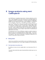
8 IMAGE ANALYSIS USING MMI CELLEXPLORER
103
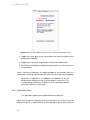
8.1 Getting started . . . . . . . . . . . . . . . . . . . . . . . . . . . . 103
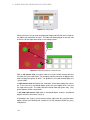
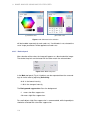
8.1.1 Encircling objects of one uniform color . . . . . . . . . . . . . . . 103
8.1.2 Encircling Objects with different uniform colors . . . . . . . . . . 105
8.1.3 Encircling Objects with color gradients . . . . . . . . . . . . . . . 105
8.1.4 Transfer to other mmi CellTools modules . . . . . . . . . . . . . . 107
8.1.5 Optimization of results . . . . . . . . . . . . . . . . . . . . . . . . 107
8.1.6 Result lists . . . . . . . . . . . . . . . . . . . . . . . . . . . . . . 107
8.2 Reference . . . . . . . . . . . . . . . . . . . . . . . . . . . . . . . 108
8.2.1 Menu reference . . . . . . . . . . . . . . . . . . . . . . . . . . . 108
8.2.2 Zoom function . . . . . . . . . . . . . . . . . . . . . . . . . . . . 109
8.2.3 Control panel . . . . . . . . . . . . . . . . . . . . . . . . . . . . . 110
8.2.4 Project panel . . . . . . . . . . . . . . . . . . . . . . . . . . . . . 120
A SERVICE
121
B LIST OF KEYBOARD SHORTCUTS
123
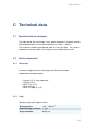
C TECHNICAL DATA
125
C.1 Required minimum workspace . . . . . . . . . . . . . . . . . . . 125
C.2 System components . . . . . . . . . . . . . . . . . . . . . . . . . 125
C.2.1 Microscope . . . . . . . . . . . . . . . . . . . . . . . . . . . . . . 125
C.2.2 Stage . . . . . . . . . . . . . . . . . . . . . . . . . . . . . . . . . 125
C.2.3 Digital camera . . . . . . . . . . . . . . . . . . . . . . . . . . . . 126
C.2.4 Computer . . . . . . . . . . . . . . . . . . . . . . . . . . . . . . . 126
C.2.5 3D Manipulator . . . . . . . . . . . . . . . . . . . . . . . . . . . . 127
ix
CONTENTS
C.2.6 mmi CellPump . . . . . . . . . . . . . . . . . . . . . . . . . . . . 127
x
MMI CellEctor
1 Security advice
1.1
General safety
• Do NOT disassemble the system. The installation of the system is done
by MMI service personnel or a designated MMI representative. Repairs,
removal or exchange of components except for the operations described
in this manual must be carried out solely by the MMI service personnel
or persons expressly authorized by MMI. If you have any problems with
the instrument, contact MMI.
• The responsibility for the correct functioning of the mmi CellEctor passes
onto the owner or user if the system is maintained or serviced improperly by persons not belonging to the MMI service team or if used for a
purpose other than that intended. MMI is not liable for damage occurring
from non-observance of these notes.
• The power supply is installed by MMI. MMI ensures that the system is
provided with the appropriate voltage. Do not change the power cords.
• Avoid wet or dusty conditions near the system. Do not attempt to use
the system if liquids get inside it. Contact MMI in such a case.
• Unplug all the electrical supply before cleaning the system. Do not use
cleaning fluids or sprays; use solely a smooth and dry cloth.
• If the stage is not calibrated, its movements can be sudden and fast.
Ensure that the work area around the stage is free of clutter and material.
• Read the manual of your microscope for microscope specific precautions. If you do not have the manual, contact your microscope provider
or MMI.
1.2 mmi CellEctor safety
• mmi CellEctor uses very thin glass capillaries that may break into splinters and injure eyes or other parts of the human body. Thus, it is compulsory for the user to wear protective gloves and clothes while working
with the mmi CellEctor.
1
1. SECURITY ADVICE
• Never point capillaries at persons. Capillaries can suddenly be loosened
from their grips under high pressure and become missiles.
• The mmi CellEctor is to be used solely for collecting cells in accordance
with the appropriate legislative requirements.
• Please ensure that all work is carried out in accordance with this manual.
2
MMI CellEctor
2 Installation
The MMI system may only be installed by an MMI service engineer or our designated representative in the laboratory of the customer. After the installation
training will be provided in the use and operation of the system. The customer
should not change the installation of the equipment.
Should you want to move an installed unit, please contact MMI for assistance.
With any malfunction of the device, please contact our service department:
service@molecular–machines.com
After installation or modification of the MMI system, an authorized specialist
must perform a thorough check to ensure that the system is in perfect condition. If your system comprises a laser, it must be ensured that the laser safety
features are functioning correctly and that the covers to protect against laser
radiation are fitted.
3
2. INSTALLATION
4
MMI CellEctor
3 The mmi CellTools
instrumentation family
The mmi CellTools are a fully modular instrumentation family, including the
following components:
• mmi CellCut: laser microdissection to isolate single cells or areas of
tissue
• mmi CellManipulator : optical tweezers to manipulate cells or beads with
an optical trap
• mmi CellEctor : automated micro-pipetting to mechanically manipulate
cells or beads with a capillary and mechanical micromanipulator
• mmi CellExplorer : pattern recognition software for PC based image
analysis
Any or all of these modules can be combined in one microscopic environment.
5
3. THE MMI CELLTOOLS INSTRUMENTATION FAMILY
6
MMI CellEctor
4 Getting started
4.1
System start-up
To start the mmi CellTools® with mmi CellEctor® follow the steps below:
• Start up the PC and allow the boot process to complete, reaching the
Windows desktop.
• Turn on the microscope control box.
• Start mmi CellTool software and wait until the software has finished the
start up and self-test procedure. For the system to work properly, all the
hardware components have to pass the hardware monitoring procedure
without errors.
• Remote control of the microscope is compulsory for the mmi CellEctor
to achieve the highest precision in the capillary vertical positioning with
respect to the slide surface. If the remote control is off, or you work with a
manual microscope, only a rough positioning of the capillary is possible.
4.2
System preparation
Follow these steps:
• Ensure that the following microscope settings are correct:
– camera orientation
– objectives calibration
– illumination settings for each objective
– camera settings for each objective
On new systems, this has already been done for you by the service
technician.
• Prepare the mmi CellCellector® for work as described in sections 6.8
and 6.9
7
4. GETTING STARTED
4.3
System turn off
• Shut down CellTools by using the
Project →Exit
command or press the close button in the top right corner of the program
window.
• Switch the microscope off.
• Shut down the PC by using the standard Windows® command.
• Let the illumination housing of the microscope cool down to the room
temperature and protect the system with the microscope cover.
8
MMI CellEctor
5 mmi CellTools – Main
application
5.1
Main window and plug-ins
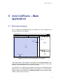
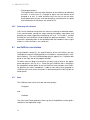
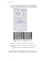
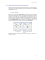
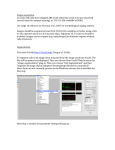
Fig. 5.1 shows the extended tool area and explains the main components of
the mmi CellTools user interface.
mmi CellTools
user database
common tools
active
application
microscope
panel
application
panel
live
video
panel
status messages
slide
overview
Figure 5.1: Structure of the mmi CellTools user interface
The major portion of the window is occupied by the live video panel, which
displays the current field of view of the microscope and serves as the main
area for interaction between the user and the system.
mmi CellTools is a single piece of software that controls all micromanipulation
devices of the mmi instrumentation family (see chapter 3). The instrumentspecific controls are located in the application panel. Switch between applications using the tabs at the top.
9
5. MMI CELLTOOLS – MAIN APPLICATION
Those user interface controls that are common to all applications are located
in the tool bar at the top of the window. The user database controls provide
access to instrument parameters for specific samples, for certain imaging situations, and for each objective (see section 5.2). The remaining common
tools on the tool bar provide elements for camera and stage control.
On systems equipped with an automated microscope, the microscope panel
provides access to z-drive (focus) control and other microscope-specific features (see chapter 7). The slide overview panel provides controls for slide
scanning and navigation (see section 5.5.2). Finally, the status messages
bar at the bottom displays current stage coordinates and camera frame rate.
To accommodate for left-handed users, the application and microscope panels
can be moved to the left-hand side using the menu item
Edit →Left-handed UI
5.2
User-specific database
All settings saved in the mmi CellTools are unique to the current user logged
in. mmi CellTools fully supports Microsoft Windows user management. During
program startup the last settings saved by the active user are loaded.
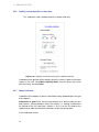
The database represents a hierarchical structure:
Slide
=⇒ Setup 1
=⇒
=⇒
..
.
Objective 1
Objective 2
=⇒ Setup 2
=⇒
=⇒
..
.
Objective 1
Objective 2
..
.
Basically the user can save all parameters for each experiment (Slide) he/she
runs separately. If the user changes settings for an experiment, settings from
recent experiments are still saved and accessible.
The Setup represents all necessary parameters to define an illumination method (bright field, fluorescence, DIC. . . ). If you change a parameter in a setup,
the change will only be reflected in the current slide.
The Objective represents all objective related settings and calibrations. If you
change an objective calibration or objective related parameter, the change only
will be reflected in the current setup and slide.
10
MMI CellEctor
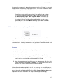
5.2.1
Slide editor
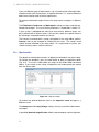
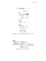
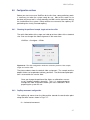
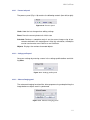
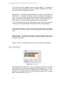
The slide selection box contains all samples you defined in the past. All documentation is saved under this name. To change the database open the slide
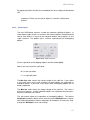
editor (Fig. 5.2) by pressing the edit button.
Figure 5.2: Slide editor
Use the + button to define a new slide. All parameters from the active slide
will be copied. Rename the slide by clicking on the name. Use the − button to
remove the active slide.
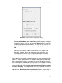
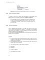
5.2.2
Setup editor
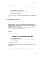
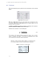
The setup selection box contains all parameters defined for the active slide. To
add, remove or change the database press the edit button. To use this editor
follow the same steps as for the slide editor described above. If you create a
new slide all setups will automatically be copied from the active slide.
Figure 5.3: Setup editor
11
5. MMI CELLTOOLS – MAIN APPLICATION
If you run different types of experiments, e.g., microdissection with bright field,
microdissection with fluorescence, or optical tweezers it is recommended to
define one setup for each of these experiments.
To rename the defined setups click on the setup name and type in a different
name.
The Filterblock, Condenser and Opticalpath settings are only used with motorized microscopes. The use of these parameters is explained in section 7.2.
If your system is equipped with more than one camera, different setups can
be associated with a certain camera. You can then switch to a specific camera
by selecting a setup defined for that camera.
The camera associated with a setup is displayed in the setup editor (column
Camera) and can be changed by clicking on the name. The camera used
should also be reflected in the setup name. On single-camera systems you
should normally select “<default camera>”.
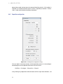
5.2.3
Objective editor
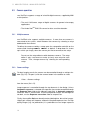
The objective selection box contains all objectives defined for the active setup.
To change the database, press the edit button to open the objective editor
(Fig. 5.4). To use this editor follow the steps for the Slide Editor described
above. If you create a new setup, all objectives will automatically be copied
from the active slide.
Figure 5.4: Objective editor
To rename the defined objective click on the objective name and type in a
different name.
The Nosepiece and Lamp Voltage settings are only used with motorized microscopes.
If specified, Nominal magnification will be used to compute various objective-
12
MMI CellEctor
dependent properties.
In addition to the parameters displayed in the Objective Editor window, the
following information is stored separately for each objective:
• Camera settings (see section 5.3.2)
• Objective related stage calibration (see section 6.9.1)
• Lens offset (see section 6.9.3)
If one of these settings is not correct, please refer to the corresponding chapter.
5.2.4
Default database reconstruction
Each user handles his/her own database. Changes in this user-specific database will not be visible for any other user.
A default database is always stored separately in a central file location. This
default database is specific for your instrument and will be set up and handled
only during installation and service.
If for some reason, a user’s database becomes unusable, the user can recover
the default database by the following procedure:
Procedure
1. Close mmi CellTools
2. Delete the following folder from the hard disc:
C:\Users\username\AppData\Roaming\MMImCUTDataBase
or for Windows XP Systems:
C:\Documents and Settings\username\Application Data\
MMImCUTDataBase
3. Open mmi CellTools
The default database will automatically be recovered and is directly visible in
mmi CellTools.
You will lose all slide and setup data contained in the user
database. You will need to recalibrate the entire system.
13
5. MMI CELLTOOLS – MAIN APPLICATION
5.3
Camera operation
mmi CellTools supports a range of scientific digital cameras, supplied by MMI
or third parties:
• The mmi CellCamera range of digital cameras for general microscopy
applications
• The Andor iXonEM EMCCD camera for ultra-sensitive detection
5.3.1
Multiple cameras
mmi CellTools also supports multiple cameras. If more than one camera is
connected to the system, switch between the cameras by selecting a setup
dedicated to that camera.
To define the camera used by a setup, open the setup editor and click on the
camera field showing <default camera> as default. A drop down list shows
up in which you simply select the camera you like to connect to that setup.
Do not use the setup editor to switch between cameras. The setup
editor is only used once to create (at least) one setup for each
camera. Then, change cameras by selecting the corresponding
setup.
5.3.2
Camera settings
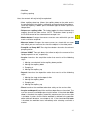
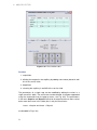
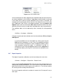
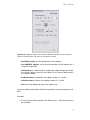
For best imaging results the camera can be controlled through a settings window (Fig. 5.5). To open it, click the camera button in the toolbar or select
Video →Camera settings
from the menu (Ctrl + R).
Image exposure is controlled through the top elements in the dialog. Unless
Automatic exposure is selected, the exposure time can be controlled through
the Exposure time slider or the adjacent input field. In Automatic exposure
mode the slider is inaccessible. If the auto-exposed images are too bright or
too dark, use the Exposure correction slider to compensate.
Finally, the amplifier Gain can be adjusted to yield brighter, but noisier images.
Higher gain settings will, however, reduce the required exposure time. For high
quality images (e.g. for publications) it is preferable to use a longer exposure
14
MMI CellEctor
Figure 5.5: Camera settings for mmi CellCamera models
time and low gain. Note that the allowed gain range is greater when automatic
exposure is off.
The controls in the bottom part of the dialog allow control over color and contrast. Use the Gamma slider to control image contrast. The default Gamma
value is 0.75, and it may be adjusted over a range of 0.01 to 2.0. Low gamma
values are recommended especially to brighten low light fluorescence images.
High gamma values reduce noise and improve the black level of the image.
The camera Mode provides color settings optimized for various applications.
For bright field, the color quality can be optimized with the Best image mode.
The camera transfers a high quality YUV4:4:4 data stream with full pixel resolution. By selecting Fastest rate, the image rate (frames per second, fps) will
be maximized. In this mode up to 20 fps (depending on your camera model)
with full pixel resolution are displayed. For fluorescence applications, the contrast can be optimized with the Low light option. The camera transfers a high
quality RGB data stream with full pixel resolution. This setting is used mainly
in combination with the Gamma and Gain setting. If you select Binning, the
camera operates at a lower resolution, but yields brighter black and white images at a very fast frame rate.
Color shifts, mainly caused by changes in lamp brightness, can be corrected
using the white balance function. To set the white balance, first locate an
empty, transparent part on the sample slide, then click the Set white balance
button. If the image is too bright or too dark the white balance fails.
The white balance function is also available in the drop down menu next to the
camera button, in the main menu under
Video →Adjust white balance
or using the keyboard shortcut Ctrl + W .
15
5. MMI CELLTOOLS – MAIN APPLICATION
Do not use the Set white balance option in fluorescence imaging.
All camera settings, including white balance, are stored separately for each
objective. This eliminates the need to adjust the camera after each objective
change. Optionally, the software uses a single white balance setting for all
objectives. This is recommended for non-automated microscopes. Select
Video →Save white balance per objective
to enable or disable this function.
5.3.3
Freeze video / live video
In fluorescence applications it makes sense to freeze the video when you have
acquired a good image. After freezing the video you can close the fluorescence shutter and go ahead with drawing and cutting your dissectates without
further photo bleaching of the fluorescence dye.
To freeze the video use the menu item
Video →Video freeze
To go back to live video presentation select
Video →Video live
5.3.4
Saving images
To save an image simply press the Save image button, use the menu item
Video →Save Image
or press Ctrl + S.
The file dialog allows you to specify the image filename and image type (JPG,
BMP, PNG and TIF). The image will be saved with maximum pixel resolution.
By selecting the Include drawings check box you can save a screen shot
from the current video image including all markers and drawings.
When saving images with drawings, the system will produce a
screenshot from the live video area, resulting in reduced pixel resolution of the saved image.
16
MMI CellEctor
Press the Copy image to clipboard button to make the current image available to other applications. The image will be copied to the Windows clipboard
in order to paste it into e.g. office and image processing applications. The
same result can be seen with the menu item
Edit →Copy Image
The Include drawings does not affect the Copy image to clipboard function. The clipboard always receives the original camera
image.
5.3.5
Recording movies
mmi CellTools allows you to record live camera images into video files (AVI
format). It supports compressed and lossless video codecs and allows you to
record time-lapse movies.
Figure 5.6: Movie recording functions in the tool bar
Click the Record button to start recording a new movie. CellTools will automatically create a new AVI file in the movie folder and record video until you
press the Stop button. If Auto-open is enabled (see below), the movie will
open in Media Player immediately after recording. Otherwise, you can access
recorded movies through the drop-down menu items Playback (open in media
player) and Open movie folder.
By default, the movie folder is located in
My Documents\mmiCellTools\Movies.
Movies are compressed with a video codec, currently either Windows Media Video 9 or XVID. To play back those movies, your
computer will require installation of the same codec. Codecs are
found on the mmi CellTools installation media.
Also note that any shapes drawn will not be recorded.
17
5. MMI CELLTOOLS – MAIN APPLICATION
5.3.5.1
Movie settings
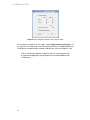
Detailed aspects of movie recording can be controlled by opening the Movie
settings dialog (Fig. 5.7).
Figure 5.7: Movie settings
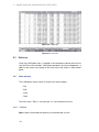
The Encoding specifies the format (codec) to store the video frames. Table 5.1 gives an overview of available encodings and their application.
Table 5.1: Movie encoding options
Encoding method
Image quality
Recommended for
Uncompressed
Lossless
Short videos
Extracting frames in full quality
Compressed – Windows
Media Video (default)
Lossy
General use
Playback primarily on Windows
systems.1
Compressed – XVID
Lossy
Color video (not usable for black and
white cameras)
Playback on any system with XVID
codec installed
To create basic time lapse movies only adjust the Time lapse factor as desired. This factor defines the speed at which the movie will play back. Enter
“1x” to turn off time lapse (standard time).
The Playback rate specifies at how many frames per second the final video
should be played back. (This is identical to the recording rate unless using
time lapse.) The default playback rate is 10 Hz and should be suitable for
general use.
The Recording interval specifies the minimum time interval between two
recorded video frames. The recording interval is computed from time lapse
factor and playback rate and is for information only.
1
To play back Windows Media Video files on Mac OS X, install Windows Media Player for
Mac OS (Flip4Mac), which is downloadable from the Microsoft website.
18
MMI CellEctor
Depending on the current camera settings and available computer
hardware it may not be possible to achieve very short recording
intervals.
To control the rates at which frames are recorded and played back, change
the Playback frame rate. If time lapse is off, the movie is played back at the
same rate at which it was recorded. When using time lapse, the recording
rate is automatically adjusted. The dialog displays the recording interval, i.e.
the time elapsed between two frames. This interval significantly influences the
size of the resulting video file.
The Movie folder input field allows you to specify the destination folder where
movie files are saved. For maximum performance, this should not be a network folder. Check the Open movie after recording option to have movies
automatically open and playback in Media Player after recording.
5.4
Motorized stage control
The movement of the motorized stage is controlled by the mmi CellTools software.
5.4.1
Mouse movement
Choose the move mode by clicking the hand tool button.
In the move mode the cursor in the video panel always appears as a hand.
By clicking and dragging the left mouse button, the stage directly follows the
mouse movement.
If stage movement does not exactly follow mouse movement, you
may need to carry out an objective calibration (see section 6.9.1).
You can quickly switch to move mode and back again by pressing Space.
5.4.2
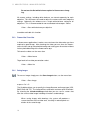
Keyboard movement
The main arrow keys and numeric pad arrow keys can be used to move the
stage in discrete steps or continuously at constant velocity (Fig. 5.8).
A single press of a cursor key moves the stage by a defined distance. By
default, this is 10% of the screen for the cursor keys and 90% of the screen for
numeric pad keys.
19
5. MMI CELLTOOLS – MAIN APPLICATION
cursor keys
numeric pad
Insert Home Page
Up
Num
Lock
/
*
-
Del
7
8
9
+
4
5
6
1
2
3
End
Page
Down
0
Enter
.
press: major steps
press: minor steps
hold: slow movement hold: fast movement
Figure 5.8: Stage movement using the keyboard
NumLock must be turned on for numeric cursor keys to work as
expected.
For moving larger distances, hold down the respective key. The velocities for
the two sets of movement keys can be set independently (see section 5.4.3).
By default, the cursor keys move slowly and the numeric pad keys move fast.
In applications where you need movement by well-defined distances only, the
continuous movement can be suppressed by enabling Caps Lock .
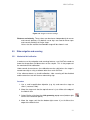
5.4.3
Stage movement settings
To change stage movement settings, press the Stage movement settings
button, click the menu bar item
Stage →Stage movement settings
or press Ctrl + P to get the window in Fig. 5.9.
Acceleration This value determines the stage motors’ acceleration for both
keyboard and mouse movement.
Reducing this value may facilitate the handling of liquid suspension samples. For all other samples we recommend using 100%.
Units For the arrow keys on the keyboard you can set the stage settings in
two different units:
• Screens (or percentage of screen)
• Micrometers (µm)
When using micrometer units, note that you may have to adapt distances
with every objective change.
20
MMI CellEctor
Figure 5.9: Stage movement settings
Distance and velocity These values can be chosen independently for cursor
and numeric pad keys. By default, cursor keys are used for minor steps
and numeric pad keys for major steps.
Values that are outside the allowable range will be shown in red.
5.5
Slide navigation and scanning
5.5.1
Mechanical limit calibration
In order to use the navigation and scanning features, mmi CellTools needs to
know the the position and dimensions of the sample. This is the purpose of
the mechanical limit calibration.
Under normal circumstances, the calibration remains valid unless the stage is
moved manually or using a software other than mmi CellTools.
If the software detects an invalid calibration, slide scanning will be disabled
and the overview scan will show a red warning sign.
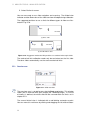
Procedure
1. Use a small magnification objective (e.g. 4x) and move the stage to
slide 1 (rearmost slide).
2. Move the stage such that the top-left corner is just visible at the edge of
the field of view.
3. Select Define origin from the slide geometry popup menu (bottom right
corner of the overview panel).
4. Move the stage such that the bottom-right corner is just visible at the
edge of the field of view.
21
5. MMI CELLTOOLS – MAIN APPLICATION
5. Select Define far corner.
You are now ready to use slide navigation and scanning. The field-of-view
indicator and the dimensions of the slide overview will adapt during calibration.
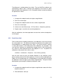
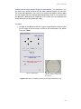
The suggested positions to use as limits for different types of slides are illustrated in Fig. 5.10.
Origin
1
Far corner
(a) Glass slide
Origin
1
Far corner
(b) mmi Membrane slide
Figure 5.10: Suggested mechanical limit positions on standard microscopic slides
The mechanical limit calibraiton needs only be carried out on the first slide.
The other slides automatically use the same mechanical limits.
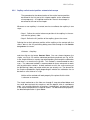
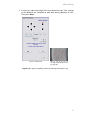
5.5.2
Overview scan
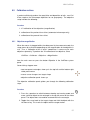
Figure 5.11: Slide overview
The overview scan is started by pressing the Start scan button. This window
shows you an overview over your sample (the “roadmap image”). If no area
of interest is defined, the whole slide will be scanned within the limits set in
chapter 5.5.1.
The current field of view is indicated with a red blinking rectangle or point.
You can move this red frame by clicking and dragging the left mouse button.
22
MMI CellEctor
The motorized xy-stage moves automatically to the chosen detail. With this
navigation method you always see the position on the slide.
You can also move to the position of interest by double clicking into the overview area with the left mouse button.
Define the area of the scan with the Select area tool. After pressing the button
you can select the area of interest in the overview window using the PC mouse.
Only the area of interest will be scanned.
Begin the scan by pressing the Start Scan button. You can always interrupt
the scan with the Stop scan button. Also pressing the Esc key will interrupt
the scan.
The scanned image can be made available to other applications. Use the
Save button or the corresponding menu item to save the overview image to
disk. Alternatively select Copy image to clipboard from the popup menu next
to the Save button to copy the overview image into the Windows clipboard and
paste it in other applications.
To erase the scanned image, click on the Clear overview image button.
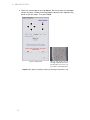
With the magnifier button you can open the large slide-overview window
(Fig. 5.12).
Figure 5.12: Large slide-overview window
The window provides the same tools as the small slide-overview panel.
Only the magnifier button behaves differently. In this big slide-overview window
the magnifier button opens the standard Windows photo viewer.
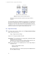
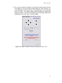
5.5.3
Multi slide handling
The mmi Multislide holder grants the user the opportunity to use more than
one slide in the xy-stage.
To move from one slide to another you can directly select the target slide
button.
23
5. MMI CELLTOOLS – MAIN APPLICATION
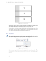
1
2
3
Figure 5.13: 1x3 Multi Slide
Alternatively you can move to another slide with the keyboard arrow keys. The
slide number indicator will automatically adjust to the current slide.
If the number in the slide number indicator does not fit with the position of the
slide holder, move the stage to slide position 1 with the keyboard arrow keys
and redefine the slide origin as described in chapter 5.5.1.
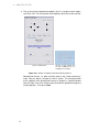
5.5.4
Pin positions
With the pin button you can save the current stage position. By clicking on the
arrow to the right you obtain the pin positions menu (Fig. 5.14).
Figure 5.14: Pin positions
You can select a pin, which moves the stage to the respective position. The
last two entries enable you to delete either the currently selected or all pin
positions.
24
MMI CellEctor
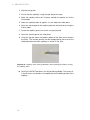
5.6
Distance measurement
Select the measurement tool to measure distances on the sample.
Figure 5.15: Distance measurement
Press the left mouse button and drag the mouse. After releasing the mouse
button you can see the measured distance (Fig. 5.15)
5.7
Calibration
5.7.1
Camera orientation
To check the camera orientation:
• Using the 40x objective, move one small and obvious point of the sample
to the upper-left corner of the video panel.
• Now press the right arrow key in the number pad. (Best using standard
step sizes for big step movement: 90% of screen)
If you move the object horizontally to the right upper corner and the object is
still on the same level, the camera orientation is correct. If the result shows
a shift between the two corners (ie. the object does not move perfectly horizontally), loosen the hex screws on the camera port and rotate the camera
carefully. Repeat this “move and observe” operation again until the object
moves on the same level across the monitor view. When the object moves in
a straight line, the camera orientation is correct. Retighten screws carefully.
25
5. MMI CELLTOOLS – MAIN APPLICATION
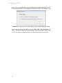
5.8
Multi-user report
Users can get information about time spent using mmi CellTools for each Windows user account.
Figure 5.16: Multi-user report
Select the menu item
Project →Usage report
or start it from
Start →All Programs →mmi CellTools →mmi MultiUser Report
A time format is hhhh:mm:ss.
5.9
Help
5.9.1
Help topics
The user manual can be opened directly inside the mmi CellTools software.
By pressing F1 on the keyboard the PDF file of the User Manual shows up.
You also launch the user manual by selecting the respective item in the Help
menu.
5.9.2
MMI online
If your PC is connected to the internet you can launch the MMI web page by
the menu item
26
MMI CellEctor
Help →MMI online
Questions about the system can be sent to MMI service staff by the item
Help →Online Support
5.9.3
Version info
Information about the currently installed software version can be found under
Help →Version info
27
5. MMI CELLTOOLS – MAIN APPLICATION
28
MMI CellEctor
6 mmi CellEctor
6.1
Principles
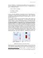
The molecular analysis of pure enriched cell populations or even of single
cells is an important prerequisite of medical genomics and proteomics and
may become essential for molecular patient profiling in the future. Up to now
this goal is often very difficult and tedious to accomplish. Therefore, MMI
developed a new analysis and cell sorting device: the mmi CellEctor. The
isolation of single and rare cells from tiny sample sources is a prerequisite
for their genotypic and phaenotypic characterization. The mmi CellEctor is
the starting point for a new integrated work flow. It facilitates the automated
isolation of any type of single and rare cells in three steps:
• Cell recognition
• Cell acquisition
• Cell deposition
The mmi CellEctor is based on:
• automated microcapillary
• automated pump
• motorized stage
To encrease the automation level the mmi CellEctor can be upgraded with:
• motorized microscope
• mmi CellExplorer, the MMI cell recognition solution
Acquisition and deposition are controlled by a high precision pump. This allows
establishing protocols that use nanoliter volumes for the separation process
and provides the basis for molecular downstream analysis in only 1µl.
29
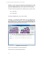
6. MMI CELLECTOR
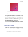
Figure 6.1: Sample area of the microscope with a ampligrid and microcapillary.
There is no mechanical stress to (non-adherent) cells: the acquisition occurs
solely by flow of the liquid surrounding a cell. Under optimum conditions, even
partly adherent cells can be acquired in this way.
There is no contact between the cells and the capillary. The capillary diameter
(10, 15, 20, 30 or 40 µm) may significantly exceed that of the cell. For example,
cells of 6 µmdiameter can efficiently be acquired with a capillary of 40 µm
diameter.
The suspension of cells can be placed either on a flat standard slide or in a
dedicated container, e.g. an IBIDI µ-Slide.
The deposition of cells may occur on various targets (deposits). Grid deposits
are matrices of either spots (like AmpliGrid) or small containers (like IBIDI well
slides). Single spot deposits may consist of a transparent cap, a PCR tube,
or a microfluidic device. Whatever the kind of the target is, its size must not
exceed the standard slide size that can be inserted in the multi-slide holder of
the stage.
The acquisition and deposition of cells can proceed in a variety of modes:
from manual mode through full automation with cells recognition by the mmi
CellExplorer. However, even in the manual mode, there is no need to manually
operate the hardware components of the system (pump, capillary): all the
operations are launched at PC by the user.
30
MMI CellEctor
The mmi CellEctor is an adjustable, open platform for any assay format. It
closes the gap between frequent and rare cell sorting. It is dedicated for the
use in the following disciplines:
• cancer research & oncology
• immunology & virology
• stem cell sciences
as well as many other applications in biomedical research, cellular diagnostics,
microbiology & virology, environmental ecology, forensics. MMI is committed
to establish specified and detailed application-related protocols in a close cooperation with the users.
All the methods applied to measure molecular changes require 100% pure
cell populations to ensure unbiased results. For the analysis of DNA, copy
number variations or single nucleotide polymorphisms are being measured.
Changes of RNA expression are analyzed by microarrays or massive parallel sequencing approaches. Protein patterns are analyzed with spectroscopic
or biochemical protocols, and epigenetic changes are detected by changes in
methylation patterns. FACS-sorting and bead-based protocols are the major
state-of-the-art methods to isolate single cells. Also a wide variety of physical
and immunological methods are employed. The mmi CellEctor helps to overcome the hurdles and drawbacks of the above mentioned methods. The mmi
CellEctor technology has been used for the enrichment of tumor cells and immune cells from disaggregated lymphnode material, blood and bone marrow
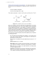
of cancer patients. For the outlined workflow of an application example, the
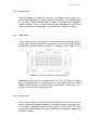
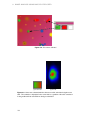
following purification steps were established: Lymphnode metastasis is dis-
(a) Preparation of cell suspension: disaggregate lymphnodes and filter cells
(b) Lyse erythrocytes from
blood or bone marrow samples
Figure 6.2: Preparation of the patient material
aggregated by the use of scalpels and filtered through a 70 micron filter to get
a cell suspension. Blood and bone marrow is treated by erythrocyte lysis, to
remove present erythrocytes, Tveito et. al. 2007 1 . In a first enrichment step,
1
Reference: Tveito, S., Maelandsmo, M. G., Hoifodt, K. H., Rasmussen, H., Fodstad,
O.:"Specific isolation of disseminated cancer cells: a new method permitting sensitive detec-
31
6. MMI CELLECTOR
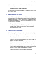
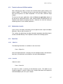
(a) specific immunomagnetic
beads and incubate under rotation
(b) magnetic separation of
immunomagnetically rosetted
cells, microscopic evaluation
and mmi CellEctor mediated
cell picking
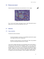
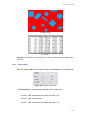
Figure 6.3: Pre-enrichment of target cells by immunmagnetic selection via targeting
a cell specific surface marker and mmi CellEctor mediated cell picking.
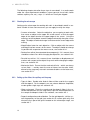
(a)
(b)
Figure 6.4: Lymphnode metastatic cells targeted with an anti EP-CAM antibody
paramagnetic beads coated with an appropriate surface-antibody were used
for the immunomagnetic enrichment. In the second step the mmi CellEctor
technology is used for individual cell picking.
6.2
Slide Types
The slides carrying the suspension of cells (sample) or serving as target for
cells have to fit the standard slide size of approx. 76 x 26 mm. Within this
constraint, a variety of slides can be used. On request, MMI can also provide
custom made slides tailored to you particular experiment.
tion of target molecules of diagnostic and therapeutic value", Clin. Exp. Metastasis 5 (24), 317
(2007).
32
MMI CellEctor
6.2.1
Sample slides
Putting a droplet of a liquid with cells on a standard flat glass slide is the
easiest way to prepare the source of cells for the capillary. The disadvantage
is, that rather sizeable and thin liquid samples are formed which evaporate
relatively quickly. There is a range of commercially available slides (e.g. IBIDI
slides) that offer some advantages as compared to this simplest solution.
6.2.2
Target slides
Target slides can either be matrices of spots (hereafter called grids) or just
a single spot. Advalytix AmpliGrid shown below is one of the standard grids
predefined in the mmi CellEctor software. In addition, custom grids can be
Figure 6.5: The mmi CellEctor Advalytix AmpliGrid
defined with up to 24 spots in arow or column (24 x 24 = 576 spots). A single
spot as a target can be just a selected spot on a grid. MMI also offers a slide
capable to hold a single transparent cap of a standard 0.2 ml PCR tube. This
kind of the target slide is called single cap.
6.2.3
Service slide
On the service slide, the capillary can be treated with various solutions for
cleaning, filling with additional reagents or diluting the reagents already present
in the capillary. MMI offers IBIDI µ-Slide 8 well as the service slide.The slide
can be purchased with different coatings (hydrophilic, hydrophobic, biopolymer
or protein coating).
33
6. MMI CELLECTOR
Figure 6.6: The mmi CellEctor 8 well service slide
6.3
Capillaries
6.3.1
Capillary types
mmi CellEctor standard glass capillaries are straight with the outer diameter
of 1 mm and the tip inner diameter 10, 15, 20, 30 or 40 µm. The capillary tip
is beveled at 45 deg. Any other capillary shapes and sizes that fit the capillary
holder may also be used, however, in such a case the handling, the calibration
and the standard usage procedures might differ from those described in this
manual.
6.3.2
Capillary handling
Please observe the safety precautions described in the first
chapter of this manual.
mmi CellEctor is delivered with a ready for use capillary placed in the capillary
holder of the 3D manipulator (illustrated below).
The following capillary replacement procedure is recommended:
34
MMI CellEctor
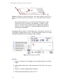
Figure 6.7: The capillary (1) is mounted in a transparent capillary holder (2) that
connects to the pump. The capillary holder is fixed in the manipulator holder (4) by a
knob (3). An additional knob (5) allows changing the rotational position of the
capillary holder. Furthermore, there is a screw at the rear side of the manipulator
holder (4) that allows adjusting the capillary tilt. The standard tilt is 45 deg.
Figure 6.8: The entire 3D manipulator can be tilted by 90 deg down to a position at
which the replacement of the capillary is facilitated. For this purpose, unscrew the
knob (6) and gently rotate the manipulator to the required position.
35
6. MMI CELLECTOR
Procedure
1. Place the 3D manipulator in the position shown in the figure 6.8.
2. Slide the capillary cover tube along the transparent capillary holder down
to the lowest position.
3. While rotating the capillary cover tube, gently press it down until it steps
into the screwing position.
4. In this position, slightly loosen the o-rings that tighten the capillary by
rotating the capillary cover tube.
5. Pull the old capillary out of the holder.
6. Pump oil out until it reaches the outer o-ring that tightens the capillary.
Take care than there are no air bubbles in the oil.
7. Insert the new capillary. While inserting, ensure that the capillary passes
both o-rings.
8. Tighten the capillary by rotating the capillary cover tube.
At this stage, it is not recommended to fill the capillary with the oil since it
is much easier to perform the 3D positioning when the capillary tip is empty.
Once the capillary 3D positioning has been done, one can proceed with filling
the capillary with oil and the buffer solution dedicated to collect cells. The
following procedure is recommended:
Procedure
1. Fill almost the entire capillary with oil. The oil boundary must not enter
the narrow part of the capillary, i.e. leave some air in the conical part of
the capillary, see Fig. 6.9.
2. Stop pumping out and wait approx. 30 seconds for the pressure in the
capillary to equilibrate.
3. Immerse the capillary into the buffer solution placed on a slide.
4. Pump in the buffer solution up to the moment the air gap between it and
the oil moves into the transparent part of the grip head, see Fig. 6.10.
5. Stop pumping in and wait for the pressure in the capillary to equilibrate.
6. Move the capillary up from the buffer solution.
The air gap between the oil and the buffer solution works well for capillaries
with the tip diameter of at least 30 µm. The narrower the capillary tip is, the
longer time it takes to equilibrate the over- or underpressure after each pumping step which makes this method impracticable for smaller capillaries. In the
later case it is recommended to collect cells in small volumes with the capillary
filled with oil and air only.
36
MMI CellEctor
Figure 6.9: Fill almost the entire capillary with oil. The oil boundary must not enter
the narrow part of the capillary, i.e. leave some air in the conical part of the capillary.
Figure 6.10: Pump in the buffer solution up to the moment the air gap between it
and the oil moves into the transparent part of the grip head.
37
6. MMI CELLECTOR
6.4
The mmi CellPump
Figure 6.11: The mmi CellPump allows to pump in and out by manually turning the
rotation knob.
Manual pumping The mmi CellPump can also be driven manually. For this,
raise the rear cover of the pump and rotate the turning knob located there,
see Fig. 6.11. Manual pumping is preferably used to fill the pump or the newly
inserted capillary with the oil. While pumping manually, you must not move the
pump piston outside the allowed range (see below).
While using capillaries with small opening, quick manual pumping may increase the pressure in the pump so that the capillary may burst.
Figure 6.12: The mmi CellPump allows to pump the shown range.
Pumping range The pump piston has a limited range of movement as indicated
in Fig. 6.12. If one of the limits has been reached and one tries to pump further
38
MMI CellEctor
in the same direction using one of the buttons mentioned above, the software
issues a warning like
Pump reached limit: pumpin IN impossible
In such a case, you have to move the piston in the opposite direction to get
out of the end switch.
6.5
Use 3D manipulator with joystick
In mmi CellEctor, the joystick is used occasionally for the manual adjustment
of the capillary position in 3D space. The horizontal XY position of the capillary
can be changed by tilting the joystick to the left or right (X coordinate) or forth
and back (Y coordinate). Its vertical Z position can be changed by turning the
joystick clockwise for lowering (Z value increases) or anticlockwise for raising
(Z value decreases) the capillary.
The speed with which the capillary moves is proportional to the
deviation of the joystick from its equilibrium position. In order to
get the feeling how quick the movement is, please observe the X,
Y and Z current values in the advanced 3D capillary positioning
dialog while using the joystick.
6.6
Typical workflow in collecting cells
While collecting cells, one picks a cell on the sample slide and deposits it on
the target slide. The typical workflow for achieving this task with mmi CellEctor
consists of the following steps:
• Ensure that the objectives are calibrated and the Z drive control is on (for
automated microscope).
• Setup the mmi CellEctor major components: the slides (sample and
deposit), the capillary and the pump.
• Calibrate the vertical contact point of the capillary on the sample and the
deposit slide.
• Calibrate the capillary tip position on the screen on the sample slide.
• Working on the sample slide in the manual mode, adjust the capillary
spacing and the pumping parameters so that the cells can efficiently be
pumped in from the sample and pumped out on the deposit.
• Collect cells using either the automatic or the workflow mode.
39
6. MMI CELLECTOR
The following chapters describe these steps in more detail. In a routine work
under the same experimental conditions (same type and size of cells, buffer
solution, capillary size, etc.), steps 1, 2 and 5 can usually be skipped.
6.6.1
Checking the microscope
Setting up the microscope for working with cells is described in detail in section 6.8 and 6.9. Here some measures you can apply to verify the setup:
• Camera orientation. Select the objective, you are going to work with,
then move an object to the upper left screen corner so that the upper
edge of the object touches the upper edge of the screen. Using the
arrow key on the keyboard, move the object horizontally along the screen
edge. The object should not change its distance to the screen edge while
moving.
• Magnification factor for each objective. Click an object with the mouse
and drag it into four corners of the screen. The object should not change
its position with respect to the mouse cursor, see section 6.9.1.
• Parfocal lens offset (for automated microscope only). If it is correct, there
should be no focus loss while changing the objectives, see section 6.9.2.
• Paraxial lens offset. If it is correct, there should be no displacement of
markers with respect to the objects they mark while changing the objectives, see section 6.9.3.
• Mechanical limits. Ensure that the mechanical limits – which are always
set on slide 1 – entirely cover the area of interest on the other slides,
otherwise the stage may not reach some destinations on the latter ones,
see section 5.5.1.
6.6.2
Setting up the slides, the capillary and the pump
• Type of slides. Decide what kind of slides will be used for the sample
and the deposit. For the deposit, one can choose between AmpliGrid,
custom grid or single cap, see section 6.8.5.
• Slide assignment. Place the sample and the deposit slides in the selected slide positions on the stage and assign the selected positions to
the sample and deposit slides in the software, see section 6.8.1.
• Deposit configuration and calibration. For the grid deposits: tell the system the geometry of the grid (see section 6.8.5, custom grids only) and
where the first spot of the grid is located on the microscope stage, see
section 6.9.7.
40
MMI CellEctor
• Capillary tilt. Insert a new capillary into the capillary holder, adjust its tilt
and set the tilt value in the software, see section 6.3.2.
• Slide plane tilt. Select the working objective and determine the plane tilt
of both slides, see section 7.4.2.
Setting of the plane tilt does not apply to a single cap.
• Pump. Ensure that
– the pump is filled with oil
– the pump piston is away from its limit positions, see section 6.4
– there are no air bubbles and no leaks between the pump and the
capillary, see section 6.3.2
6.6.3
Calibrating the capillary
• Contact point. Determine the vertical reference position of the capillary,
see section 6.9.4. On a flat slide, it is the position at which the capillary
tip touches the slide surface.
• XY position on the screen. Once the contact point of the new capillary
is known, move the capillary down and calibrate its XY position on the
screen, see section 6.9.6.
6.6.4
Finding the optimum conditions for collecting cells
Solutions containing cells as well cells themselves exhibit a broad range of
physicochemical and biological properties. Thus, the optimum conditions have
to be found for the particular cells of interest. While experimenting with new
cells and buffer solutions, one can vary the following parameters:
• Size of the capillary tip:
In principle, it should be larger than the size of the cells to be collected. If
the concentration of cells is not too large, even relatively large capillaries
(tip diameter of 40 µm) can efficiently collect small cells (approx. 5 µm).
• Orientation of the capillary tip bevel:
Rotating the capillary around its axis may affect the efficiency of catching
and depositing the cells.
• Spacing:
The distance between the capillary tip and the slide surface (spacing)
affects both the volume of the liquid necessary to be pumped in order
to pick a cell as well the volume to be pumped out at the deposit to get
the cell out of the capillary. It should be adjusted for the sample and the
deposit slide separately.
41
6. MMI CELLECTOR
• Pumping parameters:
These parameters have the major influence on the efficiency of collecting
the cells. In most cases it is enough to adjust the main volume to be
pumped in or out. In some extreme cases one has to use the other
pump parameters like pre- and over-pumping, relaxation time or speed
and acceleration of the pump, see section 6.8.3.
6.6.5
Performing cells collection
Cells can be collected using either the manual, automatic or workflow mode.
In the manual mode, moving the stage, moving the capillary up or down and
pumping are action separately launched by the user. This mode is suitable
learning the mmi CellEctor and for finding the optimum conditions. The routine work is preferably done in the workflow mode that combines these single
actions in series of actions, see section 6.6.
6.7
mmi CellEctor user interface
As described in section 5.1, the special features of the mmi CellCut, the mmi
CellExplorer and mmi CellManipulator are installed as separate plug-ins (software modules). The mmi CellManipulator plug-in appears as a separate tool
panel on the right side of the program window.
To switch from one plug-in to the other you only have to click on the appropriate tool panel, see Fig. 6.13. Once the mmi CellEctor tab is selected in
the component control panel of the mmi CellTools main window, mmi CellEctor becomes the active component. It adds its own menu items grouped as
CellEctor to the main menu and shows its own control panel, either System or
Action panel.
6.7.1
Menu
The CellEctor menu consists of two sub-menu groups
Configure
and
Calibrate
The menu item Export grid data shows up only if AmpliGrid or custom grid is
selected as the deposition target.
42
MMI CellEctor
Figure 6.13: The mmi CellEctor plug-in panel in action mode
Figure 6.14: The mmi CellEctor menu
43
6. MMI CELLECTOR
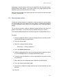
6.7.2
System panel
There are two major panels in the mmi CellEctor control panel: System panel
and Action panel. You can switch between the panels by clicking on the links
in the top right corner. The System panel shows the readiness of the major
system components. The figure below shows the system ready for use. If
one of the major system components requires calibration, the corresponding
button is highlighted red. Clicking the button with the left mouse key launches
Figure 6.15: The mmi CellEctor plug-in panel in calibration mode
the calibration procedure of this component. Clicking the button with the right
mouse button launches the configuration dialog of this component, if the corresponding item exists in the CellEctor main menu. Clicking the link Switch to
action opens the action panel.
The button Inspect Deposit shows up only for grids as deposition
targets and the button Service Slide only for non-standard deposition targets.
6.7.3
Action panel
Most of the routine work with the mmi CellEctor is done using the Action panel.
It consist of the four groups of controls:
• Manual operation
• Automatic operation
44
MMI CellEctor
• Workflow
• Capillary spacing
Here, the controls will only briefly be explained.
• Move capillary down/up. Moves the capillary down to the point and in
the way defined in the capillary calibration and configuration procedures.
Once the capillary is down, press the button again to move it up to the
idle position.
• Refocus on capillary/slide. This button toggles the focus between the
capillary tip and the slide surface. NOTE. The button shows up only if
the Z drive control of the automated microscope is on.
• Marker button Changes the mouse cursor to a cross with which you can
mark a cell to be acquired.
• Measure button Changes the mouse cursor to a hand with an arrow
with which you can measure the size of the objects in the video panel.
• Pump IN and Pump OUT Pressing these buttons launches the relevant
pumping action.
• Volume IN/OUT Two spin boxes that allow to adjust the amount of the
liquid pumped in or out, respectively.
• Acquire Launches the acquisition action that consists of the following
steps:
1.
2.
3.
4.
Moving a marked cell to the capillary down position
Moving the capillary down
Pumping in
Moving the capillary up
• Deposit Launches the deposition action that consists of the following
steps:
1.
2.
3.
4.
Moving the stage to the deposit slide
Moving the capillary down
Pumping out
Moving the capillary up
• Rinse Launches the workflow to be done solely on the service slide.
• Acquire and deposit Acquisition and then deposition are launched. The
user has to mark a cell before pressing this button. If the check box With
rinse is checked, the capillary treatment sequence on the service slide
is included. It means that the entire workflow as defined in the workflow
editor table will be done, see chapter 6.8.6. if the check box Full auto
is checked, the workflow starts immediately after selecting a cell with a
marker.
45
6. MMI CELLECTOR
• Scan for cells starts scanning of the predefined sample area, cells
recognition, acquisition, deposition and rinse, with the latter being performed only if the With rinse check box is checked.
• Capillary spacing Two spin boxes that allow adjusting the distance between the capillary tip and the surface of the sample or deposit slide.
The values in these two boxes are in effect before the capillary
starts its movement down. For changing the spacing when
the capillary is already down use the fine positioning arrows
shown below.
• These two arrows show up as soon as the capillary arrives to the down
position. Pressing one of them moves the capillary up or down in fine
steps giving the opportunity to adjust the capillary spacing. The spacing
value in the corresponding spin box is automatically adjusted and is then
used in the future movements down.
Once the fine adjustment arrows show up, the relevant spin
box is disabled.
• Rough spacing mode warning shows up when the Z drive control of
the automated microscope has been turned off or you are working with
the manual microscope. It indicates that the numbers in both spin boxes
are approximate.
Like in the system panel, clicking some buttons (capillary, pump, acquisition,
deposition, rinse) with the right mouse key launches the relevant configuration
dialogs.
If some system components are not calibrated, the affected buttons
in the Action panel are temporarily disabled(grayed).
The link Switch to system opens the system panel.
6.7.4
Distance measurements
Pressing the Measure button the Action panel changes the mouse cursor to
a hand with an arrow that allows measuring the distances in the video panel.
For this, just drag the cursor from the start to the end point of the interest and
the distance between these two points will be indicated on the screen. Every
subsequent measurement deletes the previous one. Once you are done with
the measurements, press the measure button again (which is now shown as
an arrow) to change to the cursor default shape.
46
MMI CellEctor
6.8
Configuration routines
Before you start to use mmi CellEctor for the first time, some preliminary work
is necessary to make the system ready for use. Most of this work has to
be done only once and is usually done by the MMI service technician during
the installation of the system. Some activities are recurrent, like capillary 3D
positioning of a freshly inserted capillary.
6.8.1
Choosing the position of sample, target and service slide
The multi-slide holder of the stage can hold up to three slides of the standard
size. One can change the slide assignment in the menu item
CellEctor →Configure →Slides
Figure 6.16: The slide configuration window to select the position of the sample,
target and service slide.
The picture above shows the default slide assignment. The sample and the
deposit slides can be placed at arbitrary positions. The third unoccupied position is reserved for the service slide.
Once you change the position of the slides, re-calibrations are necessary (capillary, deposit, plane tilt). Thus, it is recommended to
change the slide assignment before you start calibrations while
preparing the system for use.
6.8.2
Capillary movement configuration
The capillary tip moves from the idle position towards the destination point
along the three vectors shown in Fig. 6.17:
• A – horizontal movement
47
6. MMI CELLECTOR
Figure 6.17: Movement pathway of the capillary from idle to down position: A –
horizontal movement; B – vertical movement; C – axial movement (immerse
distance)
• B – vertical movement
• C – axial movement (immerse distance)
The user can adjust the movement characteristics in the following dialog (Fig. 6.18)
that can be opened from the main menu
CellEctor →Configure →Capillary Movement
Figure 6.18: Capillary movement configuration dialog.
The tilt of the capillary should be set equal to the value read from the capillary
holder. Immerse distance corresponds to vector C in the above figure. Slow
down distance is the last portion of the immerse distance (indicated as a
dashed line on vector C in the above figure) where the capillary moves with a
highly reduced speed in order to minimize pushing away the cells.
While moving up out of the sample, the capillary moves with the
normal speed.
48
MMI CellEctor
Both immerse as well as the slow down distance can be set for the sample and
the deposit independently. The numbers at the right hand side of the dialog (in
[mm]) are calculated from a given capillary tilt and a given immerse distance.
They help to adjust the immerse distance if the capillary has to be immersed
in liquids confined to container walls.
6.8.3
Pump configuration
Figure 6.19: Pump configuration dialog.
All the pump parameters can be set in the pump configuration dialog that can
be opened either from the main menu
CellEctor →Configuration →Pump
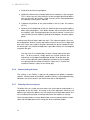
or by clicking any pump-relevant button with the right mouse button. The following pump parameters can be changed by the user:
• Volume in main volume that is pumped in if the user presses the button
Pump in or Acquire in the action panel
• Volume out main volume that is pumped out if the user presses the
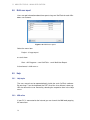
button Pump out or Deposit in the action panel
• Pre-pumping volume volume that is added to the main volume whenever the pump changes the direction (from in to out or vice versa)
• Over-pumping volume volume that is pumped in prior to the main volume to be pumped in and then pumped out after the main volume has
been pumped in. This value has no effect on the pumping out process.
49
6. MMI CELLECTOR
• Relaxation time waiting time spent for pressure to equilibrate after the
pumping process is finished
• Speed pump speed (in percent of the maximum speed)
• Acceleration pump acceleration (in percent of the maximum acceleration)
• 40 number showing the current capillary size for which the pump parameters are displayed. Click on it opens the list with available capillaries
(as shown in the figure above).
All the pump parameters are specific for a given capillary. Up to five parameter
sets can be stored for capillaries with different sizes. You can retrieve a stored
parameter set for a given capillary by selecting the corresponding capillary
size.
Whenever the pump parameters are modified, the changes are
valid for the running session only. In order to save the current set
for the future sessions, check the box Save this parameter set
before you leave the above dialog.
6.8.4
Acquisition configuration
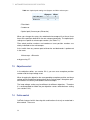
One can adjust some parameters of the acquisition process in the configuration dialog that can be opened either from the main menu
CellEctor →Configure →Acquisition
or by clicking any acquisition-relevant button with the right mouse button. In the
dialog showed in Fig. 6.20, the upper part Acquisition defines the behavior
of the single acquisition process, the lower part While scanning for cells,
scan that of the fully automated cell acquisition. Acquisition mode is presently
limited to single cells. This means that the user cannot set more than one
marker at a time to select a cell and to acquire it. However, several cells
may be collected in the capillary by repeating the acquisition step before the
deposition of the cells takes place. In such a case, one has to adjust the
volume that is pumped out during the deposition process to at least multiple
of the volume pumped in during a single acquisition step in order to ensure
that all the collected cells will leave the capillary upon deposition. Two other
options allow further modification of the acquisition process:
• Allow for acquisition without markers if this option is checked, the
system does require setting a marker to acquire a cell. If the option is
unchecked a message is issued when the user clicks Acquire button
without setting a marker prior to it.
50
MMI CellEctor
Figure 6.20: Cell acquisition configuration dialog.
• Leave capillary down after acquisition check this option if you want
to verify that the cell has indeed been caught in the capillary during the
acquisition process. If it has, you can click Deposit button to move the
capillary up and continue the process. If it has not, you have the opportunity to retry pumping the cell into the capillary by pressing Pump
IN.
Whenever the capillary is down, movement of the XY-stage is still
possible. However, please be aware that large movements (exceeding the size of the field of view) may damage the capillary
when the slide plane is significantly tilted.
These options are especially useful during the fine tuning of the acquisition
process for a given application. In the workflow mode Scan for cells acquisition is preceded by making a snapshot of the current field of view and automatic cell recognition and selection (setting markers). The sample is scanned
horizontally and vertically and the user can define the number of screenshots
that have to be made (scan a number of screens horizontally and a number
of screens vertically). The recognition of cells can be repeated a number of
times at each stage location if there are several cells of interest that can be
acquired there. Minimize fluorescence excitation option is relevant only for
the case when the automatic cell recognition takes place in the fluorescence
51
6. MMI CELLECTOR
observation mode and one wants to prevent bleaching of cells. If this option is
checked, the motorized fluorescence shutter is opened just before a screenshot is made and closed immediately afterwards.
6.8.5
Deposition configuration
Figure 6.21: Cell deposit configuration dialog.
One can adjust several parameters of the deposition process in the configuration dialog that can be opened either from the main menu
CellEctor →Configure →Deposition →Deposit
or by clicking any deposition-relevant button with the right mouse button, see
52
MMI CellEctor
Fig. 6.21. The choice of the deposit type has effect on many other settings of
the system. Presently, one can choose among three types of the deposit:
• AmpliGrid commercially available grid
• Custom grid grid defined by the user
• Single cap transparent cap placed in a holder
If the user changes the deposit type, the configuration parameters irrelevant to
the selected type are disabled. For instance, the number of rows and columns
as well the spacing are not applicable to the single cap. Changing the type
also deletes all the settings and data associated with the current deposit target
and the check box New grid(cap) inserted is automatically checked. The
basic parameters of a grid (rows, columns, spacing) can be changed only for
a custom grid. On the other hand, the number and the location of the target
spots can be selected arbitrarily on both AmpliGrid as well as on the custom
grid by changing the current row, the end in row, the current column and
the end in column.
The number of cells per spot is used by the software to determine whether or
not a given spot is already filled and the stage has to be moved to the next
spot. No further deposition is possible if all the spots of a grid are filled with
the pre-defined number of cells. The same applies to a single cap.
The remaining three options facilitate the visual control of the deposition of
cells during the automatic acquisition and deposition. In the standard deposition process, the capillary is moved up as soon as the pumping out step is
completed (including the pump relaxation time). This corresponds to N = 0 set
in the spin box After having pumped out, stay down for N seconds. Change
this number if you want the capillary be left down for an additional amount of
time (maximum 20 seconds) before it is moved up and the XY-stage moved
back to the sample. This number becomes irrelevant if the option Wait for
spot inspection is checked. In this case the XY-stage is not moved back to
the sample until the user clicks Back to sample from the context menu on the
video image.
6.8.6
Workflows editor
In mmi CellEctor a workflow is a combination of acquisition, deposition and
the capillary treatment on the service slide that is launched by a single mouse
click as a continuous series of actions. The workflow can be customized in the
following workflow editor, see Fig. 6.22.
In the example shown in the above figure, the workflow consists of four consecutive steps:
53
6. MMI CELLECTOR
Figure 6.22: The workflow editor
Procedure
1. acquisition
2. diluting the reagent in the capillary by adding some water placed in well
#1 of the service slide
3. deposition
4. cleaning the capillary in well #5 of the service slide
The parameters of a single step can be modified by editing the values in a
single row of this table. The entire rows can be deleted, inserted or appended
using the commands from the pop-up menu, see Fig. 6.23 The parameters
in the rows Acquire and Deposit cannot be changed and these rows cannot
occur more than once in this table (that is why the menu items
Insert →Acquire and Insert →Deposit
are disabled in Fig. 6.23).
54
MMI CellEctor
Figure 6.23: The workflow editor
Once the workflow has been edited and the workflow editor closed, it becomes
the active workflow in mmi CellEctor. Depending on which button is pressed
in the action panel, either the entire workflow or only its part is launched. For
example, pressing the button Rinse launches the actions on the service slide
only ("Add water" and "Clean" in the above example). Pressing Acquire and
deposit button with the check box With rinse checked launches the entire
workflow, otherwise only the acquisition and deposition steps are performed.
The workflow editor can be opened by either selecting the corresponding
menu
CellEctor →Configure →Workflow
or by pressing the right mouse button over the relevant buttons Rinse, Acquire
and deposit.
A running workflow can be interrupted any time by pressing the
ESC key on the keyboard. In such a case, the workflow terminates
after the currently running basic step is completed (capillary movement, pumping, moving the stage). If a workflow is on idle, i.e.
waiting for the next step a predefined amount of time (Stay time in
the workflow editor), pressing ESC terminates the workflow immediately.
6.8.7
Deposit inspection
The deposit inspection calibration can be launched by the menu item
Cellector →Configure →Deposition →Deposit scan
or pressing the inspect deposit button with the right mouse button opens the
configuration dialog shown below. The scanning can involve either the entire
grid (check the box Scan entire grid) or only a part of it. For the latter, define
the starting and the ending row and column.
For visual inspection, define the number of seconds the XY-stage will stay at
each spot.
55
6. MMI CELLECTOR
Figure 6.24: Configure inspection of the deposit slide.
For automatic inspection of the spots, check Apply image processing. In
this case the XY-stage waits until the recognition of cells is completed by mmi
CellExplorer. A report will be created automatically, also see chapter 6.10.6.
Prior to starting the deposit inspection with the image processing,
the correct image processing parameters have to be loaded to mmi
CellExplorer.
56
MMI CellEctor
6.9
Calibration routines
In order to efficiently perform the acquisition and deposition of cells, mmi CellEctor requires the microscope objectives be set up properly. The objective
setup includes the following
Procedure
1. XY calibration of the objectives (magnification)
2. calibration of the parfocal lens offset (automated microscope only)
3. calibration of the paraxial lens offset
6.9.1
Objectives magnification
When the mouse is dragged within the video panel in the movement mode, the
stage moves by a distance depending on the magnification of the objective in
use. Thus, a calibration of the X and Y coordinates is necessary for each
objective separately. To perform the XY calibration of an objective, select
CellEctor →Calibrate →Objective →Magnification
from the main menu or press the button Objective in the CellEctor system
panel.
Several things happen now:
• two transparent rectangles show up in the top left and the bottom right
video panel corner
• mouse cursor changes to a target shape
• objective calibration panel shows up
The objective calibration panel guides you through the following calibration
steps:
Procedure
1. Press the spacebar to switch between drawing and moving mode and
move a distinct object to the rectangle in the top left corner of the video
panel. The object does not need be centered within the rectangle.
2. Toggle the cursor back to the target shape and click theobject with the
left mouse key. This marks the object with the target marker.
57
6. MMI CELLECTOR
Figure 6.25: The mmi CellEctor plug-in panel in objective calibration mode
3. Toggle the cursor back to the hand shape and move the object to the
bottom right rectangle.
4. Toggle the cursor to the target shape and mark the object again.
5. Click Done on the objective calibration panel to finish, or Cancel to restart
the procedure.
After a successful calibration, any object dragged to any location within the
video panel should be exactly under the mouse cursor at the end of dragging.
Whenever an objective is re-calibrated, re-calibration of the XYposition of the capillary as well as of the deposit is necessary. This
is indicated by marking the Capillary and the Deposition buttons
red in the CellEctor system panel
6.9.2
Parfocal lens offset
This procedure applies to the automated microscope only.
When one changes an objective and the microscope was in focus, the new
objective requires a slightly different Z drive position to get in the new focus.
58
MMI CellEctor
The difference is called parfocal lens offset. The mmi CellTools software can
automatically refocus after a change of the objective if the offset has been
determined for all the objectives in use. Proceed as follows in order to calibrate
the parfocal lens offset:
Procedure
1. Change to the objective with the highest magnification
2. Focus the microscope
3. Change to the objective with the next smaller magnification
4. Focus the microscope
5. Select menu item Microscope →Z Drive Offset →Objective (parfocal)
6. Repeat steps 3 and 4 for the remaining objectives.
After the calibration, the microscope does not lose focus when the objectives
are changed.
6.9.3
Paraxial lens offset
Due to mechanical and optical tolerances, two objectives never have exactly
the same optical axis. The difference between the position of the optical axes
of two objectives is called paraxial lens offset. This offset manifests itself by
a small shift of pixels in the video panel when objectives are changed. The
mmi CellTools software can automatically compensate this shift if the paraxial
lens offset has been determined for each objective in use. To perform the
calibration of the paraxial lens offset, select
CellEctor →Calibration →Objective →Lens Offset (paraxial)
from the main menu or press the button Objective in the CellEctor system
panel and then click the link Offset (paraxial). In the lens offset calibration procedure, the XY displacement of a sizeable object is measured while changing
the objectives from the highest to the lowest magnification. The panel shown
below guides you through the following calibration steps:
Procedure
1. Change to the objective with the highest magnification and/or click Start
button to confirm it.
2. Two tool buttons show up:
59
6. MMI CELLECTOR
Figure 6.26: The mmi CellEctor plug-in panel in objective paraxial calibration mode
• freehand drawing tool
• drawing mover tool
Move the selected object to the center of the video panel, click the freehand drawing tool and draw the contour of the object with the mouse.
Press Del on the keyboard if you want to redraw the contour.
3. Change to the objective with the next smaller magnification
4. After the change, the previously drawn contour will move away from the
object. Re-position it using the drawing mover tool so that it again overlaps with the object.
5. Click the button Set offset and confirm the message that shows up
6. Repeat steps 3 through 5 for the remaining objectives
7. Change from the objective the smallest to the objective with the highest
magnification without deleting the drawn shape. If the procedure succeeded, the shape should overlap with the object.
8. Terminate the procedure by clicking the link Exit objective calibration
on the panel
60
MMI CellEctor
6.9.4
Capillary vertical contact position: automated microscope
The procedure for the determination of the vertical contact position
described in the first part of this chapter applies to the automated
microscope only. A simplified method for manual microscopes is
described at the end of the chapter.
Whenever a new capillary is inserted, one has to calibrate the capillary in two
steps:
• Step 1. Define the vertical reference position of the capillary in the contact with the (planar) slide.
• Step 2. Define the XY position of the capillary tip on the screen.
Defining the vertical reference position of the capillary at the contact with the
slide is done in the 3D positioning dialog accessible through the link Switch
to system or the menu
Cellector →Capillary
and than click on the button Contact Point. One can choose between the
simple, see Fig. 6.27a and the advanced positioning method, see Fig. 6.27b.
In the simple method, a step-by-step wizard guides you through the calibration
and there is no need to use joystick. This method is recommended for most
users. The advanced method is recommended for those who prefer to work
with joystick and/or numbers. As both methods result in the same accuracy of
the positioning, it does not matter which one you actually use. The wizards for
the simple method differ slightly depending on whether the calibration has to
be done on a flat slide or in a cap.
Neither of the methods will work properly if the plane tilt of the slide
is unknown or incorrect.
The simple method on a flat slide runs through 5 steps described below and
has to be done on both the sample as well the deposit slide in a deliberate
order. Just carefully follow the instructions (marked blue) and warnings (red)
in the wizard and perform the required actions. For documentation purposes,
the detailed explanation is given below.
61
6. MMI CELLECTOR
(a) Simple method. The wizard only shows
up, if plane tilt is active.
(b) Advanced method. Fixed positions only
show up, if plane tilt is active.
Figure 6.27: Capillary vertical contact point calibration windows.
62
MMI CellEctor
Capillary vertical contact position: Ampligrid or custom grid, simple method.
Procedure
1. Once the 3D positioning dialog is opened, a large target marker is shown
in the center of the screen facilitating the positioning. At this moment, the
Figure 6.28: Center of the screen indicated in the video panel.
capillary stays in the idle position which is at the maximum distance from
the slide. This is indicated by a red bar above the Z arrow (no further
raising of the capillary is possible). The system is now ready to move the
capillary towards the optical axis of the objective and to lower it towards
the slide. The first step is to change to the objective with the smallest
magnification, usually x4. Then press Next.
63
6. MMI CELLECTOR
2. The capillary reached the leftmost X position (note the red bar at the X
arrow in Fig. 6.29a) and was lowered so that its shadow should already
be seen in the screen, see Fig. 6.29b. If it is not, you have to adjust its
horizontal position first. Using the X and Y arrows, place the capillary tip
(a) The control panel.
(b) Capillary moved over the
center marker but is still
above the optical plane.
(c) Capillary lowered to the
optical plane.
(d) Capillary positioned exactly on the center marker
and to the optical plane.
Figure 6.29: Step2 of capillary vertical positioning wizard.
in the center of the target marker, as shown in Fig. 6.29c. Then, move
the capillary down or up using the Z arrows so that its tip is in focus like
in Fig. 6.29d. Then press Next.
64
MMI CellEctor
3. The system has now set the focus from the capillary tip back to the slide.
Change to the objective you anticipate to work with during collection of
cells. Then press Next.
(a) The control panel.
(b) The system has now set
the focus from the capillary tip
back to the slide.
Figure 6.30: Step3 of capillary vertical positioning wizard.
65
6. MMI CELLECTOR
4. The system further lowered the capillary, thus it is roughly in focus again,
see Fig. 6.31b. The XY position of the capillary tip on the screen can de-
(a) The control panel.
(b) The system further lowered the capillary, thus it is
roughly in focus again.
Figure 6.31: Step4 of capillary vertical positioning wizard.
liberately be chosen, i.e. does not have to be in the screen center anymore. You can adjust it using the X and Y arrows. The vertical position
of the capillary must be adjusted so that its tip gets in a gentle contact
with the slide. Use the Z arrows and the minimum speed to change the
vertical position. Then press Next.
66
MMI CellEctor
5. At the contact position, both the slide and the capillary tip should be
in focus, as illustrated in Fig. 6.32b. Press Finish to set the contact
(a) The control panel.
(b) At the contact position,
both the slide and the capillary tip should be in focus.
Figure 6.32: Step5 of capillary vertical positioning wizard.
point of the capillary tip with the slide and to complete the capillary 3D
positioning.
It is recommended to leave the check box Set default idle
position too checked. The default idle position is defined as
the maximum XZ distance from the sample while leaving the
Y coordinate unchanged. Setting user-defined idle position of
the capillary is possible in the advanced 3D positioning only.
67
6. MMI CELLECTOR
Once Finish is clicked and the wizard completed, the following dialog Fig. 6.33:
If the contact position of the capillary on the other slide is still valid, i.e. you
Figure 6.33: Dialog at the end of the capillary vertical position calibration wizard.
have replaced neither the capillary nor the other slide, select the option "still
valid". Otherwise select the second option, move to the other slide (in this
case to the deposit) and go through the calibration procedure once again.
68
MMI CellEctor
Capillary vertical contact position: Single cap, simple method The wizard for a single cap is very similar to that for the flat slide. However, before you start with
the single cap calibration, you have to ensure that the capillary contact point
on the sample slide has correctly been determined. Also, it is essential, that
the plane tilt is defined for the single cap. If it is not the case, the capillary may
break during one of the following 6 steps.
Procedure
1. Change to the objective with the smallest magnification and then move
the XY-stage so that the cap is visible on the microscope, Fig. 6.34b.
Then press Next.
(a) The control panel.
(b) The cap is visible on the
microscope and centered to
the marker.
Figure 6.34: Step1 of capillary vertical positioning wizard with a cap.
69
6. MMI CELLECTOR
2. Move the XY-stage so that the future capillary landing point within the
cap is placed in the screen center. This should be a location at the left
hand side of the cap as shown in Fig. 6.35b. Then press Next.
(a) The control panel.
(b) The capillary landing point
within the cap is placed in the
screen center and located at
the left hand side of the cap.
Figure 6.35: Step2 of capillary vertical positioning wizard with a cap.
70
MMI CellEctor
3. If necessary, adjust the height of the inner wall of the cap. Then, change
to the objective you anticipate to work with during collection of cells.
Then press Next.
(a) The control panel.
(b) Left side of the cap under high magnification working objective
Figure 6.36: Step3 of capillary vertical positioning wizard with a cap.
71
6. MMI CELLECTOR
4. Focus the microscope on the cap bottom. Be sure to focus on the upper
not on the lower surface of the cap bottom, otherwise the capillary may
break in the next steps. Then press Next.
(a) The control panel.
(b) Left side of the cap under high magnification working objective focused on upper surface of teh cap bottom.
Figure 6.37: Step4 of capillary vertical positioning wizard with a cap.
72
MMI CellEctor
5. The system moved the capillary to the position closely above the cap.
The capillary is not seen under the microscope yet. At this moment, it is
recommended to verify the position of the capillary by visual inspection
of the XY-stage. The capillary body should be above the upper right
edge of the cap in a distance exceeding the cap wall height; otherwise it
would break in the next step. Then press Next.
Figure 6.38: Step5 of capillary vertical positioning wizard with a cap.
73
6. MMI CELLECTOR
6. The system moved the capillary into the cap so that the capillary tip
stays approx. 200 µmabove the cap bottom. The capillary tip may be out
of focus at the moment, Fig. 6.39b. Now focus the microscope on the
(a) The control panel.
(b) Left side of the cap under high magnification working objective with unfocused
capillary.
(c) Left side of the cap under high magnification working objective with focused
capillary.
Figure 6.39: Step6 of capillary vertical positioning wizard with a cap.
capillary tip and fine-tune the XY position of the capillary if necessary,
Fig. 6.39c.
The capillary tip does not need to be placed in the screen center.
At the moment you press the Finish button, the system calculates the spacing
between the capillary tip and the cap bottom (206 µmin the example shown
74
MMI CellEctor
here). You can change this value later in the range from 0 (contact with the
cap bottom) to 4000 µm.
Figure 6.40: System panel after finishing capillary vertical positioning wizard with a
cap.
Large spacing values may conflict with the upper limit for the
microscope Z drive if automatic refocusing on the capillary tip
is selected or the user toggles the focus manually (using the
Refocus on capillary/slide button in the action panel).
The above calibration procedure sets not only the capillary position within the
cap but also the cap position with respect to the XY coordinates of the screen.
Thus, contrary to grids as deposit targets, there is no separate calibration
procedure for the deposit position for the cap.
75
6. MMI CELLECTOR
Capillary vertical contact position: advanced method In the advanced method, one
has to be aware of two independent 3D coordinate systems used by mmi CellEctor :
• that of the capillary manipulator
• that of the microscope with its stage.
Their relative orientation is shown in the Fig. 6.41a and Fig. 6.41b. The XY
(a) 3d manipulator
(b) stage and microscope focus
Figure 6.41: Coordinate systems used in mmi CellEctor.
planes of the capillary and of the stage work fully independently. On the other
hand, the relative position of the Z axes of the capillary and the microscope
must be determined whenever a new capillary is inserted or its position is
changed. For this purpose, the capillary is moved down to the contact position
with the slide and the microscope is focused on both the capillary tip and the
slide surface at the same time. At this moment the capillary Z position and the
position of the Z drive of the microscope are stored for future calculations.
The controls of this advanced capillary 3D positioning dialog, Fig. 6.42 perform
the following operations:
• X, Y, Z show the current position of the capillary. If you change any of
these values using the spin controls, the changes are in effect after the
Go to button has been clicked.
• Go to moves the capillary to the point defined by the current X, Y, Z
values
• Refresh updates the X, Y, Z values
• Move down moves the capillary to the point defined as the contact point
minus spacing. This button is invisible if the contact position is unknown.
• Move up moves the capillary to the point defined as the idle position
(usually the uppermost one)
• Joystick activates/deactivates the joystick. Activation of the joystick disables the seven controls mentioned above. The position indicators X, Y,
Z are, however, continually refreshed while the joystick is in use.
76
MMI CellEctor
Figure 6.42: Capillary vertical contact point calibration windows for the advanced
method. Fixed positions only show up, if plane tilt is active.
• Set IDLE position sets the idle position of the capillary
• Set CONTACT position sets the contact position of the capillary on a
sample or a grid slide.
• CAP position is visible only for a single cap as deposit target and shows
the current settings values for the capillary in the cap as determined in
the simple method.
• Calibrate motors recalibrates the capillary motors X, Y and Z
• Initialize motors initializes the capillary motors X, Y and Z
• Exit closes the dialog and moves the capillary up.
Once the capillary orientation and the tilt have been selected, proceed as follows:
Procedure
1. Ensure that the Z drive control is ON (Microscope →Z Drive Control must
be checked)
77
6. MMI CELLECTOR
2. Activate the joystick.
3. Ensure that the capillary is high enough above the stage.
4. Move the capillary within the XY plane towards the optical axis of the
microscope.
5. Lower the capillary down to approx. 2–3 mm above the slide plane.
6. Focus the microscope on the capillary tip either manually or by using the
Z drive slider.
7. Center the capillary tip on the screen using the joystick.
8. Focus the microscope on the slide plane.
9. Using the joystick lower the capillary down to the slide until it touches
the latter. The contact position can be recognized by the onset of the
sideward movement of the capillary as shown in Fig. 6.43.
Figure 6.43: Capillary starts moving sidewards, when touching the slide by moving
the capillary down.
10. Click Set CONTACT position in the 3D positioning dialog. The current X,
Y and Z values are stored as the coordinates for the down position of the
capillary.
78
MMI CellEctor
6.9.5
Capillary vertical contact position: manual microscope
Defining the vertical reference position of the capillary at the contact with the
slide is done in the 3D positioning dialog accessible through the link Switch
to system or the menu
Cellector →Capillary
and than click on the button Contact Point. Calibration of the vertical contact
position of the capillary for manual microscopes or if the plane tilt is not active
is done in a single step. Use one of the dialogs Fig. 6.44a of Fig. 6.44b. The
capillary has to be manually moved down to the contact position using either
the XYZ arrows or the joystick. Once the contact position is reached, the
button Set DOWN position has to be clicked. The idle (up) position is set by
moving the capillary to this position and pressing Set UP position.
(a) using buttons
(b) using joystick and position
numbers
Figure 6.44: Capillary 3D positioning without active plane tilt support. Also used for
manual microscopes.
79
6. MMI CELLECTOR
6.9.6
Capillary horizontal position on the screen
This calibration step is performed on the sample slide only.
Figure 6.45: Capillary horizontal contact point calibration window.
Calibration of the position of the capillary tip on the screen is done in the panel
shown in Fig. 6.45. Click Move capillary down, mark the tip on the screen
with the mouse and click Done.
6.9.7
Deposit calibration
Calibration of the deposit is done in two different ways depending on the type
of the deposit.
Calibration of grids Once the basic parameters of a grid (number of rows
and columns, spacing between them) are known, it is enough to determine
the location of the first spot (row 1 column 1, R1C1) on the XY-stage for the
software to be able to calculate the locations of the remaining spots.
In the calibration routine
80
MMI CellEctor
Figure 6.46: Deposit calibration window.
CellEctor →Calibrate →Deposition
or Deposition in the system panel the user has to set two markers at two
locations at the R1C1 spot:
• the center of the spot
• the place where the capillary has to deposit the cell(s).
The first location is used by the software to center the image on the spot during
the automatic grid inspection.
The second location is used for the deposition of cells. It may deviate from
the spot’s geometrical center in order to compensate for the asymmetry of the
droplet formed during the pumping of liquid out of the capillary. Calibration of
a single cap is made simultaneously with the calibration of the capillary position within the cap. Please refer to chapter 6.9.4 for the detailed description
of the calibration procedure. The user is guided through the calibration with a
self-explanatory wizard.
81
6. MMI CELLECTOR
6.9.8
Service slide calibration
If one works with one of the MMI standard deposition slides (AmpliGrid or
single cap) of known geometry, there is no need to calibrate the service slide.
For non-standard deposition slides, a dedicated button Service Slide shows
up in the system panel and opens a panel for a manual calibration procedure
of the service slide.
Figure 6.47: Service slide calibration window.
82
MMI CellEctor
6.10
Using mmi CellEctor
mmi CellEctor can be used in a variety of modes starting with the manual
mode, via the automatic mode ending with workflows running fully automatic
after a single click.
In the manual mode, the basic steps of acquisition and deposition like moving
the XY-stage, moving the capillary or pumping are not combined in sequence
of actions. Thus, the user can perform a single step separately using the
corresponding buttons in the action panel. Manual mode is used mainly for
the tuning of the system to new experimental conditions (type of cells and
buffer solution).
Once the optimum conditions for the movement of the capillary and pumping
have been found, one of the buttons in either automatic or workflow mode can
be used.
In the automatic mode, the work is divided in three steps: acquisition, deposition and rinse.
In the workflow mode, these three steps are combined in a series of actions
(workflow). The simplest workflow is Acquire and deposit, the most advanced
is Scan for cells. If required, the rinse step can be included in the workflows by
checking the check box With rinse. A workflow can be interrupted by pressing
Esc.
While working in either automatic or workflow mode with the automated microscope, it is compulsory to determine the tilt of the
plane both on the sample as well as on the target slide (except for
a single cap).
6.10.1
Manual pump use
The pump is delivered ready for use, i.e. it is filled with oil and with the piston
set in the backward position.
Figure 6.48: Set the pump volumes in the action panel and initiate pumping by
presseing Pump IN or Pump OUT
Pumping a predefined volume The buttons Pump IN and Pump OUT in the
Action Panel allow pumping a pre-defined volume of liquid, see Fig. 6.48.
The pump speed and acceleration can be configured as described in chapter
83
6. MMI CELLECTOR
6.8.3. Once launched, the pumping cannot be interrupted. Thus, mmi CellEctor estimates the pumping time for a given volume and issues a warning if the
time exceeds 2 minutes.
Figure 6.49: Initiate continous pumping by presseing Pumping in or Pumping out
Endless pumping Continuous pumping with the highest speed and acceleration can be done using the pump panel accessible by pressing Switch to
system →Pump, see Fig. 6.49. The pumping can be stopped by pressing the
Stop button.
6.10.2
Moving the capillary up or down
Figure 6.50: Moving the capillary up or down by presseing Move capillary up or
Move capillary down
Moving the capillary up or down is done by pressing the button Move capillary up or Move capillary down. The final down position of the capillary is
calculated from the capillary contact position with the slide surface minus the
spacing value set by the user in the action or in the capillary calibration panel.
If the user changes the spacing value while the capillary is down it will be in
effect yet in the subsequent down movement.
Button Move capillary up or Move capillary down are enabled only if both
the upper (idle) and the lower positions of the capillary are known, i.e. the
capillary is calibrated.
84
MMI CellEctor
Whenever the capillary is down, the movement of the XY-stage is arrested
except for the movement by dragging the mouse, if the user checked the latter
option in the acquisition configuration dialog.
The software automatically recognizes if the capillary is up or down
as long as the capillary movement is done solely by using the button Move capillary up or Move capillary down. The actual position of the capillary may mismatch the position concluded from
this button if the user moved capillary with joystick. In such a case,
repeatedly press the button Move capillary up or Move capillary
down to remove the mismatch.
6.10.3
Automatic modes: Acquire, deposit and rinse
Figure 6.51: Panel representing the automatic functions of mmi CellEctor
In the automatic mode, the work is divided in three steps: acquisition, deposition and rinse. In order to separate a cell of interest from the sample and
transfer it to the deposit, perform the following actions:
Procedure
1. Select a cell on the video screen by setting a marker
2. Click the Acquire button.
3. Once the selected cell has been aspired, click the Deposit button.
4. If required, click the button Rinse. The capillary moves up, the stage
moves to the to service slide and the capillary is rinsed.
5. Open the context menu by clicking on the video image with the right
mouse button and select Back to sample. The stage moves back to the
point on the sample, where the cell has been aspired.
If the cell could not be aspired in step 2, the user has the possibility to perform additional pumping step(s) by pressing button Pump in in the manual
part of the action panel (provided that the option Leave capillary down after
acquisition has been checked in the acquisition configuration dialog).
85
6. MMI CELLECTOR
Figure 6.52: Panel representing the workflow functions of mmi CellEctor
6.10.4
Acquire and deposit workflow
To acquire a cell from the sample slide and deposit it automatically to the
deposit slide mark a cell and click the button Acquire and deposit.
If the check box Full auto is checked, acquisition and deposition of
the cell is launched immediately after a marker is set. Thus, there
is no opportunity to delete a marker that has erroneously been set
on a wrong cell.
6.10.5
Scan for cells workflow
With the Scan for cells workflow, the user does not need to mark the cells
since it is done automatically be the software. This workflow is usually applied
under fluorescence conditions since the colored cells of interest can easily be
distinguished from the black background.
A single click on the Scan for cells button in the action panel launches the
following recurrent workflow:
Procedure
1. A snapshot of the video screen containing the cells is made at the starting position of the stage and is then transferred to the image processing
software mmi CellExplorer.
2. mmi CellExplorer finds the cells, marks them and sends the set of the
markers back to mmi CellEctor.
3. mmi CellEctor selects a single cell to be aspired.
4. acquisition
5. deposition
6. rinsing (if required)
7. moving back to the sample
86
MMI CellEctor
8. Depending on the settings made by the user, either another snapshot
is made at the same stage location, or the stage is moved to the next
location and the loop restarts.
In order to scan through the sample, the user can define the number of screens
horizontally and vertically in the acquisition configuration dialog, see chapter 6.8.4. Since usually there are several cells of interest within one snapshot,
the recognition and selection of cells can be repeated several times at the
same stage location.
For the fully automatic scanning to work correctly, it is compulsory
to load the correct set of parameters to mmi CellExplorer software
before you start the scan. Please refer to the mmi CellExplorer
manual for the explanation how to do it.
6.10.6
Automatic inspection and reporting of deposit grids
Figure 6.53: Inspect deposit button
By pressing Inspect deposit mmi CellEctor is capable to automatically scan
through the spots of a grid giving the user opportunity to verify the presence
of cells in the spots. The verification may be either just visual or using automatic cells recognition by mmi CellExplorer. The inspection process can be
configured as described in chapter 6.8.7.
Reports If the reporting is actived in the confiration dialog, see chapter 6.8.7,
a snapshot of each inspected spot is stored in the JPG format for documentation purposes. The image files are named RxCy.jpg where R, C represent
row and column, and x, y represent their number, respectively. The images
are stored it the folder
My Documents\mmiCellTools\AutoDoc\
\CL_InspectData_yyyy-mm-dd_hh-mm-ss\RxCy.jpg
Furthermore, a report file can be created in the ASCII tab separated format
that contains the following information:
• Spot ID number (RxCy).
• Number of cells automatically recognized in each spot during the inspection of the grid.
• Total amount of liquid pumped out to each spot.
87
6. MMI CELLECTOR
The file can be generated from the main menu item
CellEctor →Export Grid Data
6.11
Optimization of the system for collecting cells
There are two key steps in the process of collecting rare cells:
• getting a cell into the capillary at the sample
• getting the cell out of it at the target
Since there is a large variety of cells and of buffer solutions, the working parameters of mmi CellEctor have to be optimized for the given experimental
conditions. The major optimization parameters are:
• pump parameters
• spacing between the capillary and the slide surface
• size, tilt and orientation of the capillary
Please note, that prior to the tuning of the system, one has to determine the
tilt of the slide plane(s).
6.11.1
Pump parameters
In order to understand the meaning of the pump parameters, let us go through
an example of the following series of the user’s actions:
Procedure
1. Acquisition of a cell.
2. Deposition of the cell.
3. Acquisition of another cell, however, the cell could not be pumped in the
first attempt.
4. Retrial to pump the cell in.
The Fig. 6.54 shows how the pump behaves during these four actions under
assumption that the following pump parameters have been set:
88
MMI CellEctor
Figure 6.54: Panel representing the workflow functions of mmi CellEctor
• Main volume 10 nl for both in and out
• Pre-pumping volume 30 nl
• Over-pumping volume 20 nl
During the acquisition (1.) of the cell, 30 nl (pre-pumping) are pumped in at
first. We assume here that pumping out took place just prior to it, thus the
pump changes the pumping direction and 30 nl are necessary for the compensation of the overpressure remaining after pumping out. In the second
step, 20 nl are pumped in (over-pumping) that will be then pumped out in the
fourth step. Thus, over-pumping does not add net volume to the main volume.
It helps, however, to pump in cells that adhere to the slide surface. In the third
step, the main volume of 10 nl is pumped in. Thus, totally 40 nl is pumped in
during the acquisition process.
During the subsequent deposition (2.) of the cell, 30 nl are pumped out at
first (pumping direction again changed) and then 10 nl of the main volume,
totally 40 nl. The next acquisition action (C) proceeds exactly the same way as
the first one (A). However, the user launches an additional pumping-in action
(D) in order to get the cell into the capillary. Since the pump did not change
its direction (the over-pumping volume that is pumped out at the end of the
pumping in does not count), no pre-pumping volume is added to the main
volume this time.
There are no universal rules for choosing the values of the pump settings,
however, several practical hints can be given:
89
6. MMI CELLECTOR
• The smaller is the diameter of the capillary tip, the slower is the dynamics
of the fluid movement through the tip and the larger is the under/overpressure necessary to pump in/out. If the dynamics is slow, one has
to increase the pre-pumping volume, the relaxation time, as well as the
speed and the acceleration of the pump.
• Light cells can be moved into the capillary with a small main volume and
no over-pumping.
• Heavy cell objects, e.g. cells that are labeled with a number of paramagnetic beads, tend to quickly penetrate the capillary even at small main
volume values. In order to catch such cells, reduce the main pump-in
volume to nearly zero and work with over-pumping volume solely. The
pump speed and acceleration should also be reduced in this case.
• Whenever possible, use capillaries with a large tip diameter, even if the
cells are relatively small. The optimum pump parameters can be much
easier found for such capillaries and the pumping process is faster.
6.11.2
Spacing
The distance between the capillary tip and the surface of the slide affects the
efficacy of the cell acquisition and deposition in a quite significant way. There
are different practical rules of thumb for setting the spacing value depending
on the orientation of the capillary bevel with respect to the slide surface:
6.11.3
Capillary bevel parallel to the slide surface
If the capillary bevel is oriented parallel to the slide surface, the cells get into
the capillary by the vertical flow forces. Following rules apply:
• The smaller the spacing on the sample, the lower the amount of the
liquid that has to be pumped in to get a cell into the capillary. One has,
however, to take into account the size of the cells as compared to the
diameter of the capillary tip and the height of the cells.
• The above rule does not apply for pumping the cells out on the deposit.
If the deposition takes place on a dry surface, the surface tension of the
liquid has to be taken into account which, at small spacing, may prevent
the liquid from flowing out of the capillary.
• The optimum spacing on the deposit depends on the amount of liquid to
be pumped out and vice versa. Both parameters should be chosen so
that the liquid touches the deposit surface and flows out of the capillary
before a droplet is formed and falls down.
90
MMI CellEctor
• If the deposition takes place into a single cap, spacing should in principle be set to zero. Nonzero values may still be used to correct for the
liquid boundary moving upon evaporation in order to keep the capillary
tip within the liquid.
6.11.4
Capillary bevel vertical to the slide surface and cell scratching
If the capillary bevel is oriented vertically to the slide surface, the flow forces
(parallel to the slide surface) can be combined with a scratching action of the
capillary. Scratching is achieved by sliding the capillary tip along the slide
surface. The capillary will move in this way if the spacing is set to a negative
value since the capillary narrow end part will be deflected by the slide surface.
However, be aware, that the capillary may break if the negative value exceeds
-10 µm.
Please observe the safety precautions described in the first chapter of this manual. Capillary size, tilt and orientation. Some hints
concerning the size have already been mentioned above. The tilt
and the orientation can be arbitrary except for the case when the
tip bevel should be parallel to the slide surface and the tilt should
be equal to the bevel angle.
6.11.5
Collecting cells to a matrix of spots (grid)
Since there is a variety of commercially available grids, we will describe collecting of cells to AmpliGrid as an example. Most of the steps apply, however,
to all other grids as well.
If a new grid is placed under the microscope, the following operations have to
be performed in order to make the grid ready for cells:
Procedure
1. Notify the software about the new grid: Open the deposit configuration dialog, select the type of the grid, set its parameters if necessary
(custom grid) and check the option New grid inserted, if it has not automaticallybeen checked.
This deletes all the data stored for the previous grid.
2. Set the number of cells you want to deposit at each spot. Please note
that this number is used to determine whether or not the spot is full,
i.e. whether the next cell can be added to the current spot. Close the
deposition configuration dialog.
91
6. MMI CELLECTOR
3. Determine the tilt of the grid plane.
4. Optionally, determine the contact point of the capillary on the new grid.
This is necessary only if the thickness of the new grid significantly differs
from the previous one and/or a high accuracy of the spacing between
the capillary and the grid is required.
5. Calibrate the position of the spot located in the first row, first column
(R1C1).
6. Perform the first deposition at the first spot of choice leaving the capillary
down after pumping out. If the buffer solution with a cell could not leave
the capillary after having pumped out the preset volume, increase the
latter or decrease the capillary spacing to the deposit, whatever appropriate.
Continue with filling all other spots with cells. The software registers the number of deposition actions in each spot and assumes that one cell is deposited
each time. Once every spot in the grid is filled with the preset number of cells,
the entire grid is full, no further deposition is possible and the user is prompted
to replace the grid.
One can also fill a selected part or every second spot on the grid
only. To do the former, simply define the current and the end
row/column in the deposit configuration dialog. To do the latter, define a custom grid with spacing between the columns that is double
the spacing and the number of columns (rows) that is a half of the
number of columns (rows) on the actual grid.
6.11.6
Standard settings for beads
The settings in the Table 6.1 apply to 10 µmpolystyrene beads in aqueous
solution. Concentration of the beads should be chosen so that approximately
20 beads are seen at once in the field of view with a 20X objective.
6.11.7
Collecting cells to a single cap
To collect cells to a single cap, one works with a transparent cap placed in a
cap holder on the XY-stage. Assuming, that all the operations necessary to
optimize the acquisition process on the sample have already been done, one
has to calibrate the position of the cap and that of the capillary in the cap.
Once the cap position has been determined, one can proceed with the acquisition and the deposition of cells using one of the automatic modes.
92
MMI CellEctor
Table 6.1: Standard settings for beads
Capillary
Bevel orientation
Parallel to slide
Tip diameter
40 µm
Spacing to sample slide
5 - 10 µm
Spacing to AmpliGrid
50 µm
Pump
Pump in volume
10 nl
Pump out volume
100 nl
Pre-pump volume
0 nl
Over-pump volume
0 nl
Relaxation time
0 ms
Speed
100%
Acceleration
100%
93
6. MMI CELLECTOR
94
MMI CellEctor
7 Automated microscope control
mmi CellTools supports the following automated microscope types:
• Olympus IX81
• Nikon Eclipse Ti
• Nikon TE2000 E
The automated microscope control functionality must be installed by an authorized MMI technician.
7.1
Activating microscope control
To enable automated microscope control, the microscope’s controller hub must
be connected to the PC (either COM port or USB). To make mmi CellTools
connect to the microscope, activate the menu item
Microscope →Remote control
This activates control of objectives, filter block, condenser cassette, fluorescence shutter and lamp brightness. The focus knobs on the microscope body
will still be useable.
mmi CellTools will remember these settings and restore them at startup. Make
sure the microscope is connected and switched on before starting mmi CellTools.
7.2
Observation methods
The setup editor is used to define the observation methods, see section 5.2.2.
In the setup editor you define for each setup the position of the
95
7. AUTOMATED MICROSCOPE CONTROL
Table 7.1: Optical path settings for Olympus and Nikon microscopes
Olympus
Nikon
Left side port
1
5
Binocular
2
1
• Filter block
• Condenser
• Optical path (Camera port, Binocular)
When you change the setup, the motorized microscope will set these three
items to the positions defined in the new setup automatically. The optical path
settings are specific to microscope vendors (see Table 7.1).
Filter wheel position numbers and condenser turret position numbers are
clearly indicated on the microscopes.
A fast switch from any camera port to binocular and backwards is performed
in the menu
Microscope →Binocular
or by pressing F7 .
7.3
Objective control
In the objective editor, see section 5.2.3, you can save nosepiece position
number and the lamp voltage used.
When changing the objective the corresponding nosepiece position and lamp
voltage will be established automatically by the microscope. Nosepiece position numbers are clearly indicated on the microscopes.
The lamp voltage setting may be different for different objectives. Therefore
it is recommended to enable the per-objective camera white balance setting
(see section 5.3.2).
7.4
Z drive control
CellTools features built-in focusing aids and functions that rely on motorized z
drive control. These are:
96
MMI CellEctor
• Sample plane definition
• Focus memory for pin positions
mmi CellTools offers three ways to manually focus the z drive:
1. Using the vertical slider on the right-hand side for coarse focussing;
2. Using the two arrow buttons at each end of the slider for fine focusing
and
3. Using the mouse wheel.
In order to use the mouse wheel for focusing, click the mouse wheel focus
button. While the button is activated, the mouse wheel is linked to the microscope z-drive.
Of course, it is possible to refocus using the microscope’s built-in focusing
controls.
When using the manual focus wheel on the microscope, some
microscope models may not feedback the changed focus values
into the software. In order to notify CellTools that the focus has
changed, click on the numerical focus display below the slider to
update its value.
7.4.1
Required calibrations
To estimate the correct focus position requires:
• Correctly measured location of the membrane slide in three dimensions
→ Sample plane definition
• Correctly measured z-drive offsets for
– different objectives
7.4.2
Sample plane definition
The sample plane focus mechanism is a simple focussing aid based on the
assumption that the sample is planar, but slightly tilted against the horizontal
plane of the stage. As a consequence, the focus always lies on this plane,
which can be defined by three points on the slide (see Fig. 7.1).
When moving to a different location on the slide, the focus is automatically
adjusted according to the sample plane definition.
97
7. AUTOMATED MICROSCOPE CONTROL
1
2
3
Figure 7.1: Definition of a tilted sample plane. Given three arbitrary base points (1, 2
and 3), the software computes the tilt angles α and β with respect to the horizontal
plane.
While plane tilt focussing is a useful focussing aid on glass slides
and for small areas of interest, the approach is limited. By principle, this method cannot compensate for rugged and non-planar
surfaces. For such samples, it is recommended to switch plane tilt
focussing off (see below).
To properly define a plane in three dimensions, three points must be set.
These points should not be on a line. To get most precise results use a high
magnification objective for this procedure (20x or higher).
Figure 7.2: Plane tilt user interface
Procedure
1. Move to a location near the edge of your sample and focus the microscope.
2. Select Define plane point 1 from the plane tilt menu (Fig. 7.2) or press
Ctrl + 1.
3. Move to a second suitable location and focus.
4. Select Define plane point 2 or press Ctrl + 2.
98
MMI CellEctor
5. Move to a third suitable location and focus.
6. Select Define plane point 3 or press Ctrl + 3.
7. Repeat this procedure for any other slide on the tray.
Note that the positions of the plane points are displayed in the overview scan.
After the plane is defined, the sample plane focussing aid can be switched on
and off through the plane tilt button or menu (Enable plane tilt focussing). Any
of the three points can be redefined individually afterwards to refine the plane
definition.
The orientation of the sample plane is stored independently for
each slide. When changing to a slide, for which no sample plane
has been defined, plane tilt focussing will be disabled.
You may use Reset plane tilt to remove all points and start defining a plane
from scratch.
Neither the single cap nor the service slide require the determination of the plane tilt.
7.4.3
Automatic Z drive control
Each time you move the stage with the arrow keys or mouse the best Z drive
position will be calculated and the Z drive motor moved to that position. With
flat samples you immediately receive a sharp image. The more uneven the
sample is, the more you need to correct the Z position manually.
If you draw a shape or if you set a pin position the software saves the z position.
Each time you go back to the shape or the pin position, the saved Z position
will be recalled. You never need to refocus during cutting.
7.4.4
Z drive offset for slide
In the case of a slide which is non-planar, it is necessary to define a Z drive
offset for the current area. This distance can be measured and corrected
automatically.
Procedure
1. Focus microscope
99
7. AUTOMATED MICROSCOPE CONTROL
2. Select menu item
Microscope →Z Drive Offset →Slide
or press F8.
After successful calibration the scope does not loose the focus, when you
change the position of the stage slightly.
7.5
Microscope safety parameters
mmi CellTools provides functions to help prevent physical damage to the microscope objectives. These functions are always in place and do not require
manual intervention. However, under certain circumstances, they can be configured through the safety parameters dialog.
Figure 7.3: Microscope safety parameters
Open the dialog using the menu item
Microscope →Safety parameters. . .
7.5.1
Objective collision prevention
There are two situations in which mmi CellTools automatically lowers the objective turret to prevent potential damage to the objectives:
The first situation is when switching to another objective. This function is carried out automatically and does not require configuration.
The second situation is when moving the stage to a different slide. If the two
slides are not perfectly aligned the surface of the objective may scratch against
the slide’s lower surface. To reduce the risk of damage, the objective turret is
100
MMI CellEctor
lowered by a certain amount, which can be specified in the safety parameters
dialog (Slide-to-slide motion). If the slides used in your setup exhibit very high
tolerances you may wish to increase this value.
When you are using the small step arrow keys or the mouse the z drive escape
function is switched off.
7.5.2
Objective-sample collision
To prevent contact between the objectives and the specimen and to protect
the microscope itself, the range of the focus drive is automatically limited to
a certain maximum value, which can be specified in the safety parameters
dialog.
To use the current focus setting as objective-sample collision limit, press the
Read current button. To reset the limit to its default value, press Reset.
The recommended procedure for setting the objective-sample collision limit is:
Procedure
1. Select the objective with the shortest working distance (normally the objective with the highest magnification)
2. Focus the microscope
3. Open the safety parameters dialog:
Microscope →Safety parameters. . .
4. Press the Read current button
5. Add the working distance in µm to the displayed value and go to step 8,
or if the working distance is unknown proceed with step 6.
6. Carefully move the objective as close as possible to the specimen without touching it.
7. Write down the value displayed under Objective-sample collision.
8. Press the Read current button again.
9. Now enter an Objective-sample collision limit half-way between the two
positions.
10. Click OK
101
7. AUTOMATED MICROSCOPE CONTROL
7.6
Fluorescence shutter control
If installed, the microscope’s epifluorescence shutter can be opened and
closed via software. Select
Microscope →Shutter
or press F6.
102
MMI CellEctor
8 Image analysis using mmi
CellExplorer
mmi CellExplorer is an optional image analysis software module for mmi CellTools. It was developed to find, count and measure microscopic objects for
subsequent extraction or manipulation. A carefully selected and applicationadapted set of functionalities guarantees a high throughput at a comfortable
level of automation. Nevertheless, a high degree of flexibility is supported.
The mmi CellExplorer finds, counts and sorts objects primarily based on the
object colors. Secondly, the automatic distinction of various object shapes
is a particularly innovative feature. Round shapes (undifferentiated cells),
for instance, can be automatically distinguished from oval forms (differentiated cells). Objects adjacent to each other are automatically separated and
counted by the software. Finally, the object shapes found can automatically be
optimized for laser cutting.
For advanced users the mmi CellExplorer comprises complex image preprocessing that can be performed before the object finding. For this purpose the software has many different filters like image sharpness, color intensity, brightness, color space transformations, background separation by fast
Fourier transformations, gamma corrections.
8.1
Getting started
Switch from mmi CellCut or mmi CellEctor to the mmi CellExplorer by choosing the mmi CellExplorer tab. The live image is loaded to the mmi CellExplorer.
8.1.1
Encircling objects of one uniform color
By clicking on the plus left to the color label the small color panel (Fig. 8.1)
opens.
This panel shows eight fields representing eight different object types you can
search for.
103
8. IMAGE ANALYSIS USING MMI CELLEXPLORER
Figure 8.1: Color panel
Move the mouse cursor onto the displayed image and left-click on the color of
the object you would like to count. The color will be displayed on the left side
of the first of the eight color fields in the settings panel.
right-click
left-click
Figure 8.2: Detecting objects of uniform color
With a left mouse click, the color under the cursor will be entered into the
left side of the first color field. The computer would search for all objects with
color ranging from green to white. The gradient in this color field displays the
“search color”.
A right mouse click will choose the “end-color” of the color gradient to search
for. In our case of a unicolored object select the same object with a left and
the right mouse click. The color field will now be filled with green only. Only
green objects will be searched for.
A left and right mouse click onto a unicolored object searches unicolored
objects with the same color (Fig. 8.3).
If the objects are small, it can be tricky to hit the right color. By using the zoom
options of the mmi CellExplorer (section 8.2.2) the selection will be very easy
and precise.
104
MMI CellEctor
Figure 8.3: Detecting objects of uniform color: Resulting objects
8.1.2
Encircling Objects with different uniform colors
In order to search for objects with different colors you need more than one
color field. Corresponding to the eight color fields, you can define up to eight
object types for your search. In order to define the colors for those objects
activate the respective color field:
Activate the field for color editing with a left-click. Only one color field can be
edited at once. The outer frame of the color field indicates the selection status
(black for active, light gray for inactive)
Activate/deactivate the field for object search with a right-click. The inner frame
of the color field indicates the status (see section 8.2.3.4).
You can find, count and calculate objects with different colors separately with
the mmi CellExplorer software (see Fig. 8.4).
8.1.3
Encircling Objects with color gradients
Many objects show a color gradient. The mmi CellExplorer can detect them
as well as uniform colored objects. Select the start color of your gradient with
a left-click and the end color with a right-click. Differing brightness or intensity
of the same color can form the gradient too.
Note: Only activated color fields will be used for object search.
105
8. IMAGE ANALYSIS USING MMI CELLEXPLORER
Figure 8.4: Two colors selected
(a) Color field
(b) Result
Figure 8.5: Green was selected with the left mouse click, red with the right mouse
click. The selection is displayed in the color field as a gradient. All colors contained
in the gradient will be searched for during a calculation.
106
MMI CellEctor
8.1.4
Transfer to other mmi CellTools modules
After selecting your colors, click on the calculate button (green arrow) in the
process toolbar. The software will now search and mark your objects. Please
wait until the process has been completed. This can take a while for large
images.
To return to the main application, click the Return to application button at
the top of the CellExplorer panel. After switching back all detected cells are
lined out and stored in the group statistics. Now you can start the cutting or
collecting process of all marked specimens.
8.1.5
Optimization of results
If your result is not totally satisfactory you can optimize each step of the object
detection. Please refer to section 8.2.
The settings for optimizing the object detection procedure described herein
can be executed directly in the respective section of the Settings panel.
8.1.6
Result lists
8.1.6.1
Object list
The following information is available via the menu item
View →Object list
after each object detection. It displays the calculated parameters like diameter,
total area, circumference and roundness for each detected object.
8.1.6.2
Count list
Under the menu
View →Count list
the count list shows a summary of the detection results. The table lists the
number of objects as well as relative area, sample information and respective
calculated objects per unit in your sample.
107
8. IMAGE ANALYSIS USING MMI CELLEXPLORER
Figure 8.6: Object list
Figure 8.7: Count list
8.2
Reference
Once the CellExplorer tab is selected in the component control panel of the
mmi CellTools main window, CellExplorer becomes the active component. It
adds its own menu items group in the main menu and shows its own control
panel.
8.2.1
Menu reference
The CellExplorer menus consists of four main-menu groups:
• File
• Edit
• View
• Tools
The main menu “Tools” is not used yet. It is reserved for future use.
8.2.1.1
File Menu
Open Opens the window for opening a saved counting session
108
MMI CellEctor
Save Quick save of the current counting session, when it has already been
saved before
Save as . . . Opens the window for saving a counting session
Printer Setup Opens the window for printer setup
Open Image file Opens the window for loading a photo
8.2.1.2
Edit Menu
Copy Copies the current photo to the clipboard of your PC
Undo Cancels the last change of settings
Reset Resets the current photo to its initial state
Calculate Starts the analysis
8.2.1.3
View Menu
Image View Shows the current photo
Object List Shows the object list
Count List Shows the count list
Panel/Settings Switches the panel between settings and projects (see section 8.2.4)
8.2.1.4
Tools Menu
The main menu “Tools” is not used yet. It is reserved for future use.
8.2.2
Zoom function
The mmi CellExplorer contains a comfortable zoom algorithm. Moving the
slider on the right hand side of the displayed image zooms the image in or out.
With the zoom in function the mmi CellExplorer zooms into a specific part of
your image. Draw a rectangle over the respective area with the mouse button
held down. The mouse pointer will change to a cross shape.
With the zoom out function the mmi CellExplorer zooms out to the original
image size.
109
8. IMAGE ANALYSIS USING MMI CELLEXPLORER
zoom in
zoom out
zoom slider
Figure 8.8: Zoom controls
8.2.3
Control panel
The mmi CellExplorer controls are subdivided into control panels that can be
opened and closed on demand by clicking on the button to the left of the
panel’s title (Fig. 8.9).
Figure 8.9: The mmi CellExplorer control panel for cell recognition
Most panels contain a preview button. When clicked, CellExplorer will perform
all calculations defined on the respective tool panel on the original image. Use
the button to check the settings you have defined so far.
110
MMI CellEctor
8.2.3.1
Process tool panel
The process panel (Fig. 8.10) contains the following controls (from left to right):
Figure 8.10: Process panel
Undo Undo the last change when editing settings
Reset Reset the current photo to its initial state
Calculate Performs a complete analysis on the current image using all parameters defined in the control panel. After this calculation, the objects
can be transferred to mmi CellCut or mmi CellEctor.
Objects Displays the number of counted objects.
8.2.3.2
Settings profile panel
Save your settings by entering a name in the settings profile toolbar and clicking Save.
Figure 8.11: Settings profile panel
8.2.3.3
Advanced imaging panel
The advanced imaging functionalities allow preprocessing and optimizing the
image before an object search is performed.
Figure 8.12: Advanced imaging panel
111
8. IMAGE ANALYSIS USING MMI CELLEXPLORER
Smoothing You can smooth your image with the smoothing function in order
to round over edges and achieve a better counting and splitting result. By
adjusting the Smooth radius slider, you can define the level of smoothing.
The radius used for the calculation of the smoothing can be set with the slider:
• 0 is a small radius
• 10 is a large radius
By clicking the Check button, you can verify the effect.
Image Effects For manipulation of digital images, the mmi CellExplorer contains additional image editing algorithms. Pressing the Image Effects button
opens a dialog (Fig. 8.13). You can see two small versions of your image. The
left image shows a copy of the original, while the right one directly displays the
effects of the changes made by adjusting the controls.
Figure 8.13: Image effects dialog
How to use the combination of several image effects:
Evaluate the best set of image effect parameters:
112
MMI CellEctor
Procedure
1. Open the Image Effect panel
2. Change a parameter and press Copy Results to Original
3. Change as many effect parameters and press Copy Results to Original
until you found the best set of parameters
4. Close
Set the best set of image effect parameters for the use in combination with the
green arrow key
Procedure
1. Open the Image Effect Panel
2. Set the best set of parameters without using the Copy Results to Original buttons and close the Image Effect Panel with the OK button.
Contrast and Brightness
ing the sliders.
Optimize the image contrast and brightness by adjust-
The HSV register The HSV register contains further important functions for
image editing. It mainly helps with manipulating color images with a color
depth of up to 32 bits. The three sliders modify the hue, saturation and intensity/value. New colors are defined with the cursor in the color field located at
the lower part of the register. The primary colors are defined with the rainbow
tool displayed in the larger part of the window.
The HSL register In the HSL register, you can further adjust the colors, applying the same principles as described for the HSV register.
The RGB register In the RGB register, you can control the individual primary
color values. All true colors can be modified by adjusting the three sliders for
red, green and blue.
The Equalization register In the Equalization register, halftones can be controlled exactly. The distribution and frequency of the halftones (0–255 for 8-bit
images, 0–65535 for 16-bit images) is displayed in the histogram. By adjusting the sliders, halftone ranges can be shielded from the image. Just move the
slider with the left mouse button held down. You can also edit color images.
113
8. IMAGE ANALYSIS USING MMI CELLEXPLORER
Just click into the small windows below the word “histogram”. The respective
primary color will be displayed. Now the individual distribution of the colors
red, green and blue (RGB) can be filtered.
Bump Map filter The Bump Map Filter produces a surface structure like those
of freeze-cuts. It simulates a metallic surface where objects show high contrasts. You can control the illumination from punctual to flat by adjusting the
sliders left/right (Left) and top/down (Top). You can also dye the surface. In
order to do so, just move the mouse pointer within the color window.
In case you would like include the original colors of your object into the metallic
surface, increase the percentage value below the Source image quantity.
Fast Fourier Transformation The fast fourier transformation searches for edges
in the image. This transformation can mainly be used to reduce background
noise.
Gamma correction The Gamma correction is a special brightness and contrast
Special function. Especially very low light images can be improved by using
the gamma correction.
Sharpen With the sharpen function you sharpen the contour of the objects.
8.2.3.4
Color tool panel
Figure 8.14: Color panel
Color fields for different object types Open the color panel to choose up to eight
color gradients as settings for counting eight different object types. This enables you to find, count and measure object types with different colors simultaneously; the counting results are shown separately for each color. The color
fields are characterized in Fig. 8.15.
114
MMI CellEctor
(a) Color field inactive for
editing and inactive for object searching
(b) Color field active for editing (only one color field can
be edited at once), but inactive for object searching
(c) Color field active for object search but inactive for
editing.
Figure 8.15: Color fields state indicators
Standard color selection With a left mouse click on the displayed image, the
color under the cursor will be entered into the left side of the first color field.
Figure 8.16: Standard color selection
A right mouse click on the displayed image will choose the “end-color” of the
color gradient to search for.
If the objects are small, it can be tricky to hit the right color. By using the zoom
options of the mmi CellExplorer as described in section 8.2.2 the selection will
be very easy and precise.
Advanced color selection With a double left mouse click in the right or left part
of the color field a standard color menu is opened to select a new colour for
the right or left part of the color field. Select the Custom file card in the Color
menue to customize the favoured color.
The Power slider (Fig. 8.14) adjusts the intensity of the marking. You should
try to get homogeneous dark objects and a light background
• 100 is the lowest intensity
• 0 is the strongest intensity
Important: Please try to obtain objects as dark as possible!
Multimode If multimode (Fig. 8.14) is selected the parameters in the lower
setting panels defining the object shape, like object area, object roundness. . .
115
8. IMAGE ANALYSIS USING MMI CELLEXPLORER
(a) Standard colors
(b) Custom colors
Figure 8.17: Advanced color selection
will be handled separately for each color set. If multimode is not selected the
set of shape parameters will be applied to all color sets.
8.2.3.5
Mark tool panel
After selection of the colors the image will appear as a black and white image.
The darker the pixels are the better will the color match the selected color.
Figure 8.18: Mark tool panel
In the Mark tool panel (Fig. 8.18) objects can be separated from the surroundings of similar color by adjusting Sensitivity:
• 0.01 is the lowest intensity
• 1.00 is the strongest intensity
The Background suppression filters the background:
• 1 means low filter suppression
• 20 means high filter suppression
For small objects high filter suppression is recommended, while large objects
should be selected with a low filter suppression.
116
MMI CellEctor
By applying the Mark function the candidate pixels for an object will be labeled
red.
Important: Please try to mark all objects in red with a white background.
8.2.3.6
Split tool panel
The mmi CellExplorer contains a mode for automatic splitting of objects. In
microscopic images of cells or structures the relevant objects are often located
next to each other in a way that the computer detects those objects as one
single structure. The toolbar split is used for separating these overlapping
objects:
Figure 8.19: Split tool panel
For the separation of overlapping objects activate the box Split.
Adjusts the intensity of the split factor:
• 0 is a low split factor
• 1 is a high split factor
The Min line slider selects the shortest length of the split line. If you select
a very small value, many small segments of larger objects are separated as
individual objects. If you enter a very large value, overlapping objects are no
longer separated.
The Max line slider selects the longest length of the split line. The value is
preset to maximum. If large individual objects are separated into two parts,
you have to decrease the value.
The split feature allows the separation of overlapping objects. The feature
Singlesplit separates objects once, while the feature Multisplit cross-checks
after separating whether another separation of the objects is necessary. Separating with Multisplit is time-consuming!
117
8. IMAGE ANALYSIS USING MMI CELLEXPLORER
8.2.3.7
Find tool panel
With the find tool panel you may adjust the size and roundness of the selected
objects.
Figure 8.20: Find tool panel
Min area and Min diam define the smallest object area and diameter, which
are counted. Max area and Max diam defines the largest object size and
diameter, which are counted.
Use Min c/a and Max c/a to filter by roundness: All objects with roundness
between the Min c/a and Max c/a value are counted.
Definition of the roundness in mmi CellExplorer :
c circumference2
=
a
4π · total area
(8.1)
The roundness will separate different geometrical shapes such as circles,
squares, rectangles and ellipses. The results are independent from shape
size and allow you to separate shapes by geometry.
Attention: In binary images, objects appear as a collection of pixels; therefore, objects are never entirely round or rectangular.
Table 8.1: Roundness of simple objects
geometry
118
roundness
circle
≈ 1.0
square
≈ 1.5
rectangle
≈ 2.0
ellipse, 1:2
≈ 4.0
MMI CellEctor
(a) Original image
(b) Results
Figure 8.21: Example for calculating the roundness of different objects independent
from size
8.2.3.8
Shapes toolbar
With the shape toolbar the contours of the selected objects can be optimized.
Figure 8.22: Shapes tool panel
The Factor defines a percentage correction of the shape size:
• Factor < 1.00: reduction of the shape size (Min: 0.8)
• Factor = 1.00: no correction
• Factor > 1.00: increase of the shape size (Max: 1.2)
119
8. IMAGE ANALYSIS USING MMI CELLEXPLORER
The Constant parameter adds a pixel correction to the shape size:
• Constant = 0.00: no pixel correction
• Constant > 0.00: shape size increases by “constant” pixels (Max: 50)
The pixel correction can be used to compensate for the laser cutting width
independent from the object size.
With the Smoothing feature the contours of the selected objects can be
smoothed:
• Smoothing = 0: no smoothing
• Smoothing > 0: increase smoothing of object contours (Max: 100)
8.2.4
Project panel
The mmi CellExplorer project panel shows all images contained in the current
session. You can choose whether the image is displayed in the work image
panel using the checkboxes on the left of the images. You can also delete an
image from the current session by marking it with the mouse and clicking the
Delete button.
120
MMI CellEctor
A Service
Service should only be performed by qualified MMI personnel or our designated representative(s). The MMI system contains no user-serviceable parts.
For questions about your instrument (technical, consumables, warranties)
please contact:
Europe and Asia:
B Molecular Machines & Industries AG (MMI)
Flughofstrasse 37
8152 Glattbrugg
Switzerland
T +41 – (0)44 – 8 09 10 10
u +41 – (0)44 – 8 09 10 11
North America:
B MMI Molecular Machines & Industries Inc.
P.O. Box 348
Haslett, MI 48840
USA
T +1 – (603) 629 9536
u +1 – (321) 978 0304
m www.molecular–machines.com
k service@molecular–machines.com
121
APPENDIX A. SERVICE
122
MMI CellEctor
B List of Keyboard Shortcuts
General
Caps Lock
Suppress continous stage movement . . . . . . . . . 20
Ctrl + P
Stage movement settings . . . . . . . . . . . . . . . . 20
Esc
Interrupt current process
F1
Display user manual . . . . . . . . . . . . . . . . . . . 26
Space
Switch between moving and drawing mode . . . . . . 19
. . . . . . . . . . . . . . 23, 83
Camera control
Ctrl + R
Open camera settings . . . . . . . . . . . . . . . . . . 14
Ctrl + S
Save an image . . . . . . . . . . . . . . . . . . . . . . 16
Ctrl + W
Set white balance
. . . . . . . . . . . . . . . . . . . . 15
Microscope control
Ctrl + 1
Define first sample plane point . . . . . . . . . . . . . 98
Ctrl + 2
Define second sample plane point . . . . . . . . . . . 98
Ctrl + 3
Define third sample plane point
F6
Open/close fluorescence shutter . . . . . . . . . . . 102
F7
Switch between camera and binocular
F8
Define z drive offset for current slide . . . . . . . . . 100
. . . . . . . . . . . . 99
. . . . . . . . 96
123
Keyboard shortcuts
Navigation
cursor keys
numeric pad
Insert Home Page
Up
Num
Lock
/
*
-
Del
7
8
9
+
4
5
6
1
2
3
End
Page
Down
0
Enter
.
press: major steps
press: minor steps
hold: slow movement hold: fast movement
124
MMI CellEctor
C Technical data
C.1
Required minimum workspace
The table top for the microscope, laser, optical equipment, computer monitor
and keyboard requires a minimum workspace of 1.20 m × 0.90 m.
The computer should be positioned under or near the table. The camera–
computer connection cable is 2 m long to ensure reliable data transfer.
C.2
System components
C.2.1
Microscope
Inverted or upright research microscope with fluorescence port.
Supported microscope models:
•
•
•
•
•
C.2.2
Olympus IX-71 (non-motorized)
Olympus IX-81
Nikon Ti (S, U, E)
Nikon Ni (U, E)
Nikon TE 2000 (S, U, E)
Stage
Scanning stage with stepper motors.
Scanning area:
120 × 100 mm2
Repositioning accuracy:
< 1 µm
Step resolution:
0.078 µm
125
APPENDIX C. TECHNICAL DATA
C.2.3
Digital camera
mmi CellCamera MXF285c
•
•
•
•
•
•
•
IEEE1394b (FireWire) color CCD camera
2/3" interline transfer frame readout CCD
Temperature controlled active Peltier cooling
signal to noise ratio: > 62 dB
On board integrated color processor for high quality color calculation
1392 × 1040 pixels with up to 20fps
Ultra high sensitivity
mmi CellCamera DXA285cF
•
•
•
•
•
•
IEEE1394a (FireWire) interline transfer color CCD camera
2/3" interline transfer frame readout CCD
Super HAD technology
signal to noise ratio: > 56 dB
1392 × 1040 pixels with up to 15 fps
Ultra high sensitivity
mmi CellCamera DXA285F
•
•
•
•
•
IEEE1394a (FireWire) interline transfer CCD camera
2/3" interline transfer frame readout CCD
Super HAD technology
1392 × 1040 pixels with up to 15 fps
Ultra high sensitivity
Andor iXonEM+ EMCCD Camera 897
• EMCCD Technology: Even single photon signals are amplified above the
noise floor. Full QE of CCD chip is harnessed (no intensifier).
• RealGainTM : Absolute EMCCD gain selectable directly from a linear and
quantitative scale.
• TE Cooling to −100°C: Critical for elimination of dark current detection
limit.
C.2.4
Computer
Suitable computer workstation models are preselected and tested by MMI.
Only use computer hardware supplied through MMI. Before performing hard-
126
MMI CellEctor
ware modifications, contact service.
mmi CellTools supports Microsoft Windows XP, Windows 7 and Windows 8 in
32-bit and 64-bit configuration.
C.2.5
3D Manipulator
Travel range:
25 mm
Resolution:
0.025 µm
C.2.6 mmi CellPump
127