1
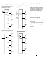
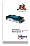
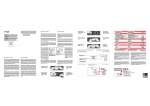
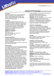
II. Parameters
UT-1208 8-PORT RS-485 HUB
USER MANUAL
I. Summary
With a double-core and non-stop inside design, UT-1208 is a
RS-485 bus splitting hub specially designed to meet the requirements
of RS-485 under sophisticated electromagnetic field environment.
A transmission rate as high as 115.2 KBPS is supported by this
product.What's more, photoelectrical isolation technology is
adopted for RS-485 interface to avoid induction of lighting or surge
into the converter and equipments to make sure the safety and
reliability of signal transmission. The built-inphotoelectrical
isolator and the 1,500W surge protection circuit can provide a
high isolation voltage of 2,500V for an efficient restriction of
lighting and ESD, and at the same time, lighting strike and
grounding interference can be reduced to the least extent. This
product is suitable for outdoors engineering with adoption of
outside switch power supply.
Under RS-485 mode, the determination circuit adopted can
determine the direction of the data stream and switch the control
circuit on a automatic basis for an very easy solution of the longexisted transmission delay of RS-485. The transmission distance
is as far as 1,200 meters with a very stable performance. This
product is widely used in express way toll system,road monitoring
system and electricity monitoring system with nice performance
and competitive price.
RS-485 star topology bus connection is provided by UT-1208
RS-485 HUB. Short circuit and open circuit is provided for all
the terminals. Photo electrical isolation of 2,500V is provided.
Re-construction of RS-485 bus structure and network range
splitting can be easily realized to improve communication reliability.
In the case of lighting strike or equipment failure, the affected
range shall be isolated to make sure the normal function of other
ranges. This feature can increase greatly the reliability of existing
RS-485 with achievement of shorter time for network maintenance.
Proper application of UT-1208 RS-485 HUB can help you with a
nice design of RS-48 system of high stability.
1
Interpretation of front panel indicators:
1. Interface features: compatible with RS-232C and RS-485
standards of EIA/TIA.
2. Electric interface: RS-232C interface for the 1st -3rd pins
of the 5-PIN terminals, and RS-485 interface
for the 4th 5th pins of the 5-PIN terminals.
3. Transmission media: twisted-pair cable or shielded cable.
4. Working mode: asynchronous half-duplex.
5. Signal indication: 11 signal indicator including power (PWR),
send(TXD), receive(RXD) and failure(E1-E8).
6. Isolation degree: a isolation voltage of 2,500V RMS 500VDC
non-stop and DC/DC isolationmodule.
7. Transmission rate: 300BPS-115.2K.
8. Protection grade: RS-232 interface 15KV ESD protection,
RS-485 interface 1,500W lighting strike surge
protection for each line.
9. Transmission distance: 0-5km (115,200-300BPS)
10.Measurements: 210mmX130mmX33mm
11.Working environment: -40℃to 80℃, relative humidity 5 % t o 95%.
II. Panel and signal indicators
There are 11 indicator lights on the front panel of UT-1208,
and on the back panel there are 1 5-pin terminal for RS-485 or
RS-232 input and 8 ports 3-pin terminals for photo electrical
isolation input ports.
PWR--Power, green for power on.
TXD--Data sending indication, green for normal
transmission from INPUT port to OUTPUT ports 1-8.
RXD--Data receiving indication, yellow for normal
transmission from OUTPUT ports 1-8 to INPUT port.
E1-E8--Failure alarm indicators for ports 1-8, the lights
stay ON to indicate short circuit or wrong signal
connection of ports 1-8. E1 is for port 1, E2 for port
2, and so on. Problems can be determined by the user
according to different light indicators.
IV. Electric interfaces and definitions:
RS-232C/RS-485 definition
GND
RXD
485+
TXD
4851 2 3 4 5
485+ 485- GND
1 2 3
Fig 3. RS-232C/RS-485 input interface
Fig 4. RS-485 output interface
1.RS-232C/RS-485 input interface definition
5-PIN Terminal Interface
1
Figure 1. Front Panel of UT-1208
Definition
Signal Direction
TXD
OUT
2
RXD
IN
3
4
5
GND
485+
485-
2.RS-485 output interface definition
5-PIN Terminal Interface
Figure 1. Back Panel of UT-1208
2
RS-485
1
485+
2
485-
3
GND
3
V. Applicatios of UT-1208 8-Port RS-485 HUB
1.Application in connection from RS-232C serial port of
main control machine to 8 RS-485 interfaces.
3. Applications in connection from RS-232C serial port of main
control machine to multiple RS-485 interfaces,or in expansion
from existing RS-485 BUS to multiple RS-485 interfaces,and a
maximum of 128 RS-485 hubs can be connected simutaneously to
RS-485 BUS.
RS-485 device A
RS-485 device A
Port 1
RS-232
Main control
machine
1
2
3
4
5
RS-232
RS-485 device B
Port 2
( UT-1208 )
Main control
RS-485 device C
Port 3
machine
OR
RS-485 device D
Port 1
1
2
3 IP RS-232 Port
4
Port 2
5 IP RS-232 Port
( UT-1208 )
RS-485 device B
RS-485 device C
VI. Alarm and Protection of RS-485 Port Failures
Efficient solutions of RS-485 ports failures hall greatly increase
the liability of RS-485 device connections. The short circuit protection
fuction of all the 4 ports for subordinate machine shall work under
turn-off mode.Any failure of any specific RS-485 port shall only
influence the RS-485 BUS system connected to that port,all
systems connected to other ports will not be effected. Failed ports
and other devices connected can be determined easily for solution
by users based on the alarm indicators.
Port 3
RS-485 device D
RS-485 Bus
VII. Prtection of Power and Lighting Strike
Port 4
Port 4
RS-485 device E
RS-485 device E
Port 5
Port 5
RS-485 device F
RS-485 device F
Port 6
Port 6
RS-485 device G
RS-485 device G
Port 7
Port 7
RS-485 device H
Port 8
Outside samll-size power suply of DC 9-48V/350mA is adopted.
Never user any other un-regulated power supply to avoid damage
caused to your products.
1,500W lighting strike protection is available for all the RS-485
interfaces of UT-1208 for efficient restriction of lighting strike and
ESD. Grounding has to be ensured for a safe and stable
communicationss.
RS-485 device H
Port 8
2. Application in expansion from existing RS-485 BUS to 8
RS-485 interface. A maximum of 128 RS-485 hubs can be
connected simutaneously to RS-485 BUS.
RS-485 device A
RS-485 device A
Port 1
Port 1
RS-485 device B
RS-485 device B
RS-485 Bus
Port 2
Port 2
( UT-1208 )
RS-485 device C
RS-485 device C
Port 3
Port 3
RS-485 device D
RS-485 device D
Port 4
Port 4
RS-485 device E
RS-485 device E
Port 5
Port 5
RS-485 device F
RS-485 device F
Port 6
Port 6
RS-485 device G
RS-485 device G
Port 7
Port 7
RS-485 device H
RS-485 device H
Port 8
4
Port 8
5
6