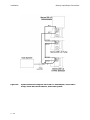
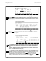
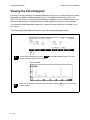
1
Series 200 UV/VIS Detector
User’s Manual
Release History
Part Number
09936504
Release
B
Publication Date
June 2000
Any comments about the documentation for this product should be addressed to:
User Assistance
PerkinElmer
710 Bridgeport Avenue
Shelton, Connecticut 06484-4794
U.S.A.
Or emailed to: [email protected]
Notices
The information contained in this document is subject to change without notice.
Except as specifically set forth in its terms and conditions of sale, PerkinElmer makes
no warranty of any kind with regard to this document, including, but not limited to, the
implied warranties of merchantability and fitness for a particular purpose.
PerkinElmer shall not be liable for errors contained herein for incidental consequential
damages in connection with furnishing, performance or use of this material.
NOTE: TotalChrom is the updated version of the software previously marketed as
Turbochrom. This product is compatible with TotalChrom and Turbochrom version 6.1.x.
Copyright Information
This document contains proprietary information that is protected by copyright.
All rights are reserved. No part of this publication may be reproduced in any form
whatsoever or translated into any language without the prior, written permission of
PerkinElmer, Inc.
Copyright © 2003 PerkinElmer, Inc.
Produced in the USA.
Trademarks
Registered names, trademarks, etc. used in this document, even when not specifically
marked as such, are protected by law.
PerkinElmer is a registered trademark of PerkinElmer, Inc.
TotalChrom Client/Server and TotalChrom Workstation are trademarks of PerkinElmer, Inc.
Turbochrom is a trademark of Applera Corporation.
Electromagnetic Compatibility (EMC)
Safety and Regulatory Information
Safety and Regulatory
Information
S
Electromagnetic Compatibility (EMC)
United States
This product is classified as a digital device used exclusively as industrial, commercial, or
medical test equipment. It is exempt from the technical standards specified in Part 15 of the
FCC Rules and Regulations, based on Section 15.103 (c).
Europe
All information concerning EMC standards will be in the Declaration of Conformity and
these standards will change as the European Union adds new requirements.
S -1
Safety and Regulatory Information
Safety and Regulatory Information
Safety and Regulatory Information
Your Series 200 UV/VIS Detector was manufactured and tested at the PerkinElmer facility
in Shelton, Connecticut. The following Safety and Regulatory Information is provided for
your information and should be read before proceeding to the installation section.
Symbols and Conventions Used in this Manual
The following graphic symbols and graphic text formats are used in this manual to set apart
important safety information.
A warning indicates an operation that could
cause personal injury if precautions are not
followed.
A caution indicates an operation that could
cause instrument damage if precautions are
not followed.
Notes emphasize significant information in a
procedure or description.
S -2
Safety and Regulatory Information
Safety and Regulatory Information
Symbols Used on the Instrument
There are two different types of warning symbols that appear on the instrument.
This symbol indicates an operation (or condition on the instrument) that could cause personal injury if precautions are not followed.
This can be any type of hazard.
When you see this symbol, refer to the safety
pages in the manual for further information.
Consulter les documents d’accompagnement.
This symbol indicates the danger of electric
shock, if precautions are not followed, due to
the presence of high voltage.
Attention. Risqué de choc électrique.
Additional graphic symbols used on the instrument are the following:
Alternating voltage.
Protective conductor terminal.
Indicates the off position of the main power switch.
Indicates the on position of the main power switch.
This symbol indicates a hot surface.
Figure S-1. Additional symbols used on the instrument.
S -3
Safety and Regulatory Information
Safety and Regulatory Information
Warnings/Labels on the Instrument (Label Location on Rear Panel)
3
2
1
4
5
6
7
Figure S-2. Location of labels on the Series 200 UV/VIS rear panel.
Label No.
(in photo)
Explanation
1
Safety information
2
Instrument name, part number, serial number, CE mark
3
Fuse, voltage, frequency and power information
4
Do not restrict air intake or exhaust
CAUTION
Attention: N’obstruez pas l’arrivée ou l’évacuation de l’air.
5
Grounding circuit continuity is vital for safe operation of equipment.
Never operate equipment with grounding conductor disconnected.
WARNING
6
WARNING
7
WARNING
S -4
Débrancher le cordon d’alimentation avant d’ouvrir da continuité des
masses est essentielle. Pour un fonctionnement sans danger. Ne jamais utiliser l’équipment si le fil de terre n’est pas raccordé.
For protection against fire hazard, replace only with same type and rating
of fuse.
Afin d’assurer la protection contre les risques d’incendie, remplacer
uniquement par un fusible de même type et de même courant nominal.
To avoid electrical shock, disconnect power supply before changing fuse.
Disconnect supply whenever cover is removed.
Avertissement: Afin d’eviter les risques d’électrocution, mettez l’appareil
hors tension avant de changer le fusible. Mettez l’appareil hors tension
chaque fois que vous retirez le couvercle.
Safety and Regulatory Information
Safety and Regulatory Information
Warning for Front Panel
You may need to open the front panel to replace a lamp. Chapter 7, Maintenance, explains
this procedure. The following illustration contains safety information for the procedure.
Allen bolt and Allen wrench
used in lamp replacement
procedure.
Location of label
Figure S-3. Front Panel with door open (for a lamp replacement)
Turn the Detector power switch to the OFF
position, and unplug the AC line cord from the
AC outlet before loosening the Allen bolt.
S -5
Safety and Regulatory Information
Safety and Regulatory Information
Electrical Warnings – General
The instrument should be used according to
the instructions provided in this manual. If
used otherwise, the protection provided by the
instrument may be impaired.
Connect the instrument to an AC line power
outlet that has a protective ground connection.
To ensure satisfactory and safe operation of
the instrument, it is essential that the protective ground conductor (the green/yellow lead)
of the line power cord is connected to true electrical ground. Any interruption of the protective ground conductor, inside or outside the
instrument, or disconnection of the protective
ground terminal may impair the protection
provided by the instrument.
Do not operate the instrument with any covers
or parts removed.
Do not attempt to make adjustments,
replacements or repairs to this instrument
except as described in the accompanying User
Documentation. Only a PerkinElmer service
representative or similarly trained and
authorized person should be permitted to
service the instrument.
Use only fuses with the required current rating
and of the specified type for replacement.
Whenever it is likely that the electrical protection of the Series 200 UV/VIS Detector has been
impaired, power the Series 200 UV/VIS Detector off, disconnect the line cord from the electrical outlet, and secure the instrument against
any unauthorized operation.
S -6
Safety and Regulatory Information
Safety and Regulatory Information
This instrument contains a lithium battery
that provides backup power for retaining data
stored internally. There is a danger of battery
explosion should the battery inadvertently be
replaced with an incorrect type or model of
lithium battery. The battery must be replaced
by a PerkinElmer service representative or
similarly trained and authorized person. The
expended battery is to be disposed of in
accordance with the battery manufacturer's
recommendations.
Observe the following guidelines for electrical safety:
•
Service on electrical components should be performed only by a qualified PerkinElmer
service representative or similarly trained and authorized person.
•
Always turn off the all components to the Series 200 UV/VIS Detector and disconnect the
power cord from the electrical outlet before you remove any covers.
•
Never operate the Series 200 UV/VIS Detector with any covers or parts removed.
•
Use only fuses with the required current rating and of the specified type for replacement.
Do not use makeshift fuses or short-circuit the fuse holder.
•
The instrument is to be positioned in a clean area free of dust, smoke, vibration, and corrosive fumes, out of direct sunlight, and away from heating or cooling units or ducts.
•
The instrument must be positioned so the power switch on the rear panel can be easily
reached by the operator.
•
There must be an adequate and stable power source for all system components.
S -7
Safety and Regulatory Information
Safety and Regulatory Information
Environmental Considerations
The Series 200 UV/VIS Detector was designed for indoor use and will function correctly
under the following ambient conditions:
Temperature
10 – 35 °C
Relative Humidity
20 – 80% noncondensing
Altitude
0 – 2000 m
Safe operation
5 - 40 °C
Do not operate the Series 200 UV/VIS Detector in
an explosive atmosphere.
S -8
Safety and Regulatory Information
Safety and Regulatory Information
Internal Warning Labels
WARNING
Hot
NITROGEN
INPUT
3 PSI MAX.
Ultraviolet radiation from this device can
cause eye injury; wear suitable protective
goggles when changing or adjusting the
lamp.
If the detector has been operated recently,
the lamp assembly will be very hot. Check
carefully before touching to avoid personal
injury. Replace lamp with PerkinElmer part
number N292-0149.
Do not exceed 3 PSI for Nitrogen input
S -9
Safety and Regulatory Information
Safety and Regulatory Information
Nitrogen Purge
In some cases (for example, in cold rooms or when operating at wavelengths of 200 nm or
lower), it is recommended that you purge the monochromator (via the purge inlet) with purified nitrogen during use. The flow of nitrogen gas will help reduce or minimize thermal
expansion/contraction of the monochromator, and, in cold rooms, prevent moisture from condensing inside the monochromator housing. Use only connecting tubing that is free of softeners or placticizers. Purge with nitrogen at approximately 1-2 psi. (3 psi maximum). Allow 10
to 12 minutes for the monochromator to become completely filled. Continue this nitrogen
flow while the instrument is in use. Purging is particularly important when the instrument
is removed from a cold room and placed in a high-humidity room at ambient temperature.
Detector Flowcell
The standard 12 µL flowcell has a normal flow of 1 mL/min of 50/50 ACN/H2O. For additional information, refer to Chapter 7, Maintenance for the specific procedures on flowcell
maintenance.
If buffers are being used, flush the flowcell
with water to remove all buffers prior to
maintenance. Buffer may precipitate and
clog the flowcell.
Flowcell backpressure should not exceed 500
psi. Damage to the flowcell and detector
occurs at higher pressures.
Do not overtighten the flowcell connections.
Damage to the flowcell could result.
S - 10
Safety and Regulatory Information
Safety and Regulatory Information
Storage Conditions
The Series 200 UV/VIS Detector may be stored under the following conditions:
•
Ambient temperature is –20 to +60 °C
•
Ambient relative humidity is 20 to 80% noncondensing
•
Altitude is in the range 0 to 12 000 m
Dimensions and Weight
The physical dimensions of the Detector are:
Weight:
11.4 kg (25 lbs.)
Height:
16.7 cm (6-9/16 in.)
Width:
33.8 cm (13-5/16 in.)
Depth:
48.6 cm (19-1/8 in.)
Additional Electrical Considerations and Warnings
Installation Category
This instrument is able to withstand transient overvoltage according to Installation Category II as defined in IEC 1010-1.
Pollution Degree
This equipment will operate safely in environments that contain nonconductive foreign matter up to Pollution Degree 2 in IEC 1010-1.
Do not operate the instrument with any covers
or parts removed.
Observe the following guidelines:
•
Service on electrical components should be performed only by a qualified PerkinElmer
service representative or similarly trained and authorized person.
•
Be sure the power cord is the correct one for your laboratory. The line cord used must
meet the national safety agency’s guidelines for the particular country of use.
•
Some power cords available from PerkinElmer are illustrated below:
S - 11
Safety and Regulatory Information
Safety and Regulatory Information
N orth A m erica
N E M A -5-15
0998-8986
O ld B ritish S tand ard
B S 546
India
0999-1423
E urope
CEE 7
"S chuko"
0 999-1415
B ritish S tandard
B S 13 63
U nite d K ingdo m
0999-141 4
E urope
S w itzerlan d
0999-1413
A ustralia
E TS A S /86
0999-1417
E urope
Italy
0999-1 422
Israel
0999-1424
D enm ark
0 999-1416
Japan
0999-1425
Susceptability to RF Interference
The Series 200 UV/VIS detector complies with the EMC standards for RF emission. However, it has a small RF susceptibility. An RF field strength of 3 V/M in the frequency range
of 80 to 1000 MHz may cause a 1 x 10⁻³ AU deflection on the chromatographic baseline. This
implies that if a device, such as a 5W walkie-talkie carried by a security guard, is used at a
distance of 10 feet from the detector, a spike or peak on the chromatographic baseline of 1 x
10-3 AU may occur. If you are concerned that such an event may occur, we recommend that
walkie-talkie restriction notices be posted in the laboratory. Cell phones, beepers, and other
similar devices operate in a much higher frequency range and do not cause interference.
Fuses
Note
Service on electrical components should be performed
only by a qualified PerkinElmer service representative
or similarly trained and authorized person The fuses in
the power entry module can be changed by the user.
The following fuses are in the power entry module to protect the instrument:
100, 120, 220, 230/240 VAC at 50/60 Hz: 1.6 Amp, Type T (H - high interrupting capacity), 5
x 20 mm, 250V rated, P/N 0999-1690.
Use the 240V selection on the power entry module for 230/240 VAC nominals.
S - 12
Safety and Regulatory Information
Safety and Regulatory Information
Quality Control/Good Laboratory Practices
Quality Control
The user should develop appropriate quality control procedures for the Series 200 UV/VIS
Detector to ensure suitability for its intended use. These procedures typically consist of periodic performance verifications and routine inspections and suitability tests.
Certificate of System Control
Each Series 200 UV/VIS Detector is carefully built and tested in a controlled system in
accordance with the requirements specified in its applicable PerkinElmer Final Assembly
and Test Specification.
Each instrument is certified to meet its functional and performance specification upon
release to shipment. The integrity of this quality system is routinely audited and is certified
by the British Standards Institution as meeting all requirements of ISO 9001:1987.
Instrument Performance Verification (IPV)
To maintain functional performance, PerkinElmer recommends a yearly Instrument Performance Verification (IPV) of the Series 200 UV/VIS Detector and its other system components by a PerkinElmer Service Engineer to ensure its operation within published
specifications. These tests consist of measuring the most important UV/VIS characteristics
such as noise drift and wavelength accuracy. Certification is available for regulatory compliance. Contact your local PerkinElmer Sales and Service office.
Routine Inspection and Suitability Test
Prior to any sample analysis, a system suitability test, which closely resembles the intended
assay, should be performed to ensure that the LC system is operating within established criteria (e.g., peak resolution, peak asymmetry, precision, retention time, column plate count,
pressure limits, signal/noise ratio, etc.)
While the Universal Test Mix (UTM) P/N 0089-0893 can be used for a system check, we recommend that you develop a separate system suitability test and acceptance criteria for each
of your assays.
Hazardous Chemicals
Before using mobile phase solvents, you should be thoroughly familiar with all hazards and
safe handling practices. Observe the manufacturer’s recommendations for use, storage and
disposal. These recommendations are normally provided in the material safety data sheets
(MSDS) supplied with the solvents.
S - 13
Safety and Regulatory Information
Safety and Regulatory Information
Some chemicals used with this instrument
may be hazardous or may become hazardous
after completion of an analysis. The responsible body (e.g., Lab Manager) must take the
necessary precautions to ensure that the surrounding workplace and instrument operators are not exposed to hazardous levels of
toxic substances (chemical or biological) as
defined in the applicable Material Safety
Data Sheets (MSDS) or OSHA, ACGIH, or
COSHH documents. Venting for fumes and
disposal of waste must be in accordance with
all national, state and local health and safety
regulations and laws.
Definitions in Warning for Hazardous Chemicals
Responsible body:
“Individual or group responsible for the use and maintenance of equipment, and for ensuring that operators are adequately trained.” [per IEC
1010-1, Amendment 2]
Operator:
“Person operating equipment for its intended purpose.” [per IEC 1010-1,
Amendment 2]
OSHA:
Occupational Safety and Health Administration (United States)
ACGIH:
American Conference of Governmental Industrial Hygienists
COSHH:
Control of Substances Hazardous to Health (United Kingdom)
S - 14
Safety and Regulatory Information
Safety and Regulatory Information
Series 200 Operating Precautions
To protect yourself from harm and to prevent malfunctioning of the system, please observe
the following guidelines when operating the UV/VIS Detector:
•
Before using the instrument, pay attention to the warnings presented in the beginning of
the manual.
•
Wear the appropriate protective clothing, including safety glasses and gloves, when preparing samples and solutions for use with this instrument.
•
Always follow the correct safety procedure and the manufacturer's recommendations
when using solvents.
•
Keep solvents with a boiling point less than 30 °C under helium (10 kPa) in an optional
solvent cabinet (for example, the SEC 4).
•
Do not keep buffer solutions in the system when the instrument is not in use, since salt
may crystallize out.
•
Do not use acidic chlorides with pH less than 7; they can cause corrosion. Chloroform and
tetrachloromethane decompose slowly and form HCl.
•
Do not use chloride TRIZMA buffers since they form HCl in equilibrium. Use phosphate
buffers instead.
•
Do not use inorganic acids, concentrated organic acids or acidic buffer solutions.
•
Ensure that the system is flushed with degassed solvent.
•
Ensure that the other instruments in the system are ready to run.
•
Ensure that all connecting communications and power cables are correctly installed for
your analysis.
•
It is possible to clean the exterior surfaces of the instrument with a soft cloth dampened
with a mild detergent and water solution. Do not use abrasive cleaners or solvents.
S - 15
Safety and Regulatory Information
Safety and Regulatory Information
Solvents
•
Always use clean solvents. Solvents which have been distilled in glass (HPLC Grade) are
recommended.
•
Filter the solvents and buffers through a 0.5-micron medium as an additional precaution.
•
Degas all aqueous and most organic solvents prior to use.
•
Store flammable solvents or solvents which may form hazardous by-products when the
instrument is shut down, by following the recommended shutdown procedure.
•
Check compatibility of solvent(s) with the type of column(s) being used.
•
Know the relative polarity and miscibility of the solvents being used.
Solvents with Low Boiling Points
Do not use liquids that have a boiling point less than 30 °C.
Do not use carbon disulfide or other solvents
which have an auto-ignition temperature
below 110 °C.
Buffers
Exercise care when using buffers in conjunction with organic solvents. NEVER LEAVE
BUFFERS IN THE SYSTEM OVERNIGHT. Buffers left in the system can form salt crystals
which may cause premature injector valve failure and plug the transfer tubing and sample
needle. To remove buffers, flush the system with water followed by methanol or isopropanol.
Remember to change the flush solvent from methanol or isopropanol to water before using
buffers.
S - 16
Safety and Regulatory Information
Safety and Regulatory Information
Corrosion
The following corrosion precautions apply to the standard (stainless steel) UV/VIS and the
biocompatible (titanium) UV/VIS Detectors.
Standard
All parts of the Series 200 UV/VIS Detector that contact mobile phase are made of stainless
steel, KelF, and quartz. Some of these materials are extremely sensitive to acid chlorides. If
you have questions about your mobile phase or flush solvent, contact a PerkinElmer representative. Refer to the table below.
Table S-1. Solvents Which May Corrode the Series 200.
Aqua Regia (80% HCl, 20% HNO3)
Hydrogen Peroxide
Anhydrous Chloride
Dichloromethane
Sulfuric Acid (Conc.)
Hydrochloric Acid (20% and 37%)
Hydrofluoric Acid (20%, 50%, and 75%)
Copper Chloride
Bromine
Freon 12 (wet)
Chlorinated solvents
Hydrofluorosilicic Acid (20%)
Hydrobromic Acid (20%)
Ferric Chloride
Ferrous Chloride
Mercuric Chloride (Dilute)
Biocompatible
All parts of the Series 200 UV/VIS Detector that contact the mobile phase (from the pump)
and flush solvent are made of titanium, fluoropolymers, or glass. This makes the Series 200
UV/VIS Detector inert to the most common mobile phases that are used for biological assays.
If you have questions about your mobile phase, contact a PerkinElmer representative. Refer
to the table below.
Aqua Regia and sulfuric acid are known to
dissolve titanium.
Table S-2.
Solvents Which May Corrode the Series 200.
Aqua Regia (80% HCl, 20% HNO3)
Hydrogen Peroxide
Dichloromethane
Anhydrous Methanol
Chlorinated solvents
Sulfuric Acid
S - 17
Safety and Regulatory Information
Safety and Regulatory Information
Solvents with Auto-Ignition Temperature Below 110 °C
Certain solvents have a temperature at which they are combustible upon contact with a
heated surface, even in the absence of a spark or other source of ignition. A list of common
solvents with their auto-ignition temperatures are in Table S-3.
Do not use carbon disulfide or other solvents
which have an auto-ignition temperature
below 110 °C.
Table S-3. Auto-Ignition Temperatures of Common LC Solvents.
S - 18
Solvent
Auto-Ignition
Temperature (°C)
Carbon Disulfide
100
Diethyl Ether
180
Cyclohexane
260
Hexane
261
Petroleum Ether (naphtha)
288
Pentane
309
Tetrahydrofuran
321
Dioxane
366
Propanol
404
iso-Octane
418
Ethanol
423
Isopropyl Ether
443
Dimethylformamide
445
Methanol
446
Isopropanol
455
Methylethylketone
474
Acetonitrile
524
Ethyl Acetate
524
Toluene
536
Acetone
538
Benzene
562
Safety and Regulatory Information
Safety and Regulatory Information
Pressure Buildup
Over time, you may observe a gradual increase in the system operating pressure. If you
observe pressure readings greater than 3.45 MPa (500 psi) above the normal operating pressure of your analysis, the following items may need attention:
•
If you are injecting “clean” samples and there is no other apparent cause for the pressure
build-up, remove, disassemble, and clean the flowcell.
•
If you are injecting “dirty” samples, the flowcell may be clogged or the column packing
material may have retained contaminated particulates. Remove and clean the flowcell,
and replace the column.
•
The column end fitting or column frit may be plugged. Replace the end fitting or frit to
relieve excess pressure.
•
In-line filters may be plugged. Replace the filter element.
S - 19
Safety and Regulatory Information
Warnings from the User’s Manual
Warnings from the User’s Manual
Generic Warnings
Before installing or operating the Detector, read the following information concerning hazards and potential hazards. You should ensure that anyone involved with installation and/or
operation of the instrument is knowledgeable in both general safety practices for the laboratory and safety practices for the. Detector. Get advice from your safety engineer, industrial
hygienist, environmental engineer, or safety manager before you install or use the instrument.
Moving the Detector
Although the Series 200 UV/VIS Detector weighs only 11.4 kg (25 lbs), improper lifting can
cause injury to the back. Exercise caution when lifting.
High Voltage
The Series 200 UV/VIS Detector contains high voltage (up to 375 volts). Before removing the
outside cover to change the lamp, detach the line cord from the Detector and wait at least
one minute.
Ultraviolet Radiation
The deuterium lamp emits ultraviolet radiation. Exposure to ultraviolet radiation can cause
permanent damage to the eyes and blindness. This can occur by opening the detector head.
You must wear approved protective goggles whenever there is a potential for exposure to
ultraviolet radiation from the deuterium lamp. The instrument should be turned off and
unplugged before removing or exchanging the lamp. The lamp must be correctly positioned
in its cradle before operating the detector.
S - 20
Safety and Regulatory Information
S - 21
Warnings from the User’s Manual
Safety and Regulatory Information
S - 22
Warnings from the User’s Manual
Table of Contents
. Safety and Regulatory
Information . . . . . . . . . . . . . . . . . . . . . . . . . . . . . . . . . . . . . . . . . . . . . S-1
Electromagnetic Compatibility (EMC) . . . . . . . . . . . . . . . . . . . . . . . . . . . . . . . .
United States . . . . . . . . . . . . . . . . . . . . . . . . . . . . . . . . . . . . . . . . . . . . . . . .
Europe . . . . . . . . . . . . . . . . . . . . . . . . . . . . . . . . . . . . . . . . . . . . . . . . . . . . .
Safety and Regulatory Information . . . . . . . . . . . . . . . . . . . . . . . . . . . . . . . . . .
Symbols and Conventions Used in this Manual . . . . . . . . . . . . . . . . . . . . . .
Symbols Used on the Instrument . . . . . . . . . . . . . . . . . . . . . . . . . . . . . . . . .
Warnings/Labels on the Instrument (Label Location on Rear Panel) . . . . . .
Warning for Front Panel . . . . . . . . . . . . . . . . . . . . . . . . . . . . . . . . . . . . . . . .
Electrical Warnings – General . . . . . . . . . . . . . . . . . . . . . . . . . . . . . . . . . . .
Environmental Considerations . . . . . . . . . . . . . . . . . . . . . . . . . . . . . . . . . . .
Internal Warning Labels . . . . . . . . . . . . . . . . . . . . . . . . . . . . . . . . . . . . . . . .
Nitrogen Purge . . . . . . . . . . . . . . . . . . . . . . . . . . . . . . . . . . . . . . . . . . . . . . .
Detector Flowcell . . . . . . . . . . . . . . . . . . . . . . . . . . . . . . . . . . . . . . . . . . . . .
Storage Conditions . . . . . . . . . . . . . . . . . . . . . . . . . . . . . . . . . . . . . . . . . . . .
Dimensions and Weight . . . . . . . . . . . . . . . . . . . . . . . . . . . . . . . . . . . . . . . .
Additional Electrical Considerations and Warnings . . . . . . . . . . . . . . . . . . .
Quality Control/Good Laboratory Practices . . . . . . . . . . . . . . . . . . . . . . . . .
Definitions in Warning for Hazardous Chemicals . . . . . . . . . . . . . . . . . . . . .
Series 200 Operating Precautions . . . . . . . . . . . . . . . . . . . . . . . . . . . . . . . .
Solvents . . . . . . . . . . . . . . . . . . . . . . . . . . . . . . . . . . . . . . . . . . . . . . . . . . . .
Solvents with Low Boiling Points . . . . . . . . . . . . . . . . . . . . . . . . . . . . . . . . .
Buffers . . . . . . . . . . . . . . . . . . . . . . . . . . . . . . . . . . . . . . . . . . . . . . . . . . . . .
Corrosion . . . . . . . . . . . . . . . . . . . . . . . . . . . . . . . . . . . . . . . . . . . . . . . . . . .
Solvents with Auto-Ignition Temperature Below 110 °C . . . . . . . . . . . . . . .
Pressure Buildup . . . . . . . . . . . . . . . . . . . . . . . . . . . . . . . . . . . . . . . . . . . . .
Warnings from the User’s Manual . . . . . . . . . . . . . . . . . . . . . . . . . . . . . . . . . . .
Generic Warnings . . . . . . . . . . . . . . . . . . . . . . . . . . . . . . . . . . . . . . . . . . . .
Moving the Detector . . . . . . . . . . . . . . . . . . . . . . . . . . . . . . . . . . . . . . . . . . .
High Voltage . . . . . . . . . . . . . . . . . . . . . . . . . . . . . . . . . . . . . . . . . . . . . . . . .
Ultraviolet Radiation . . . . . . . . . . . . . . . . . . . . . . . . . . . . . . . . . . . . . . . . . . .
S-1
S-1
S-1
S-2
S-2
S-3
S-4
S-5
S-6
S-8
S-9
S-10
S-10
S-11
S-11
S-11
S-13
S-14
S-15
S-16
S-16
S-16
S-17
S-18
S-19
S-20
S-20
S-20
S-20
S-20
Table of Contents . . . . . . . . . . . . . . . . . . . . . . . . . . . . . . . . . . . . . . . . 1-i
Table of Contents
Getting Started with the Detector . . . . . . . . . . . . . . . . . . . . . . . . . . . 1-1
1. Series 200 UV/VIS LC Detector Overview . . . . . . . . . . . . . . . . . . . . . . . . . . . . 1-2
Series 200 UV/VIS LC Detector Features and Benefits . . . . . . . . . . . . . . . . . .
NOTES TO REMEMBER WHEN USING THE DETECTOR . . . . . . . . . . . .
Main Components of the Series 200 UV/VIS LC
Detector . . . . . . . . . . . . . . . . . . . . . . . . . . . . . . . . . . . . . . . . . . . . . . . . . . . . . . . . .
Keyboard and Display . . . . . . . . . . . . . . . . . . . . . . . . . . . . . . . . . . . . . . . . .
Input/Output Connector Panel . . . . . . . . . . . . . . . . . . . . . . . . . . . . . . . . . . .
Rear Panel . . . . . . . . . . . . . . . . . . . . . . . . . . . . . . . . . . . . . . . . . . . . . . . . . .
Powering Up the Detector . . . . . . . . . . . . . . . . . . . . . . . . . . . . . . . . . . . . . . . . .
Understanding the Main Screen . . . . . . . . . . . . . . . . . . . . . . . . . . . . . . . . . .
Using the Keyboard and Display . . . . . . . . . . . . . . . . . . . . . . . . . . . . . . . . . . . .
Summary of the Keyboard Functions . . . . . . . . . . . . . . . . . . . . . . . . . . . . . .
Keyboard Operations . . . . . . . . . . . . . . . . . . . . . . . . . . . . . . . . . . . . . . . . . .
Instrument Specifications . . . . . . . . . . . . . . . . . . . . . . . . . . . . . . . . . . . . . . . . .
1-3
1-3
1-4
1-4
1-4
1-6
1-7
1-8
1-9
1-10
1-13
1-20
Installation . . . . . . . . . . . . . . . . . . . . . . . . . . . . . . . . . . . . . . . . . . . . . 2-1
2. Preparing Your Laboratory . . . . . . . . . . . . . . . . . . . . . . . . . . . . . . . . . . . . . . . . 2-2
Required Air Quality . . . . . . . . . . . . . . . . . . . . . . . . . . . . . . . . . . . . . . . . . . . 2-2
Unpacking Your Detector . . . . . . . . . . . . . . . . . . . . . . . . . . . . . . . . . . . . . . . . . 2-4
Items Included . . . . . . . . . . . . . . . . . . . . . . . . . . . . . . . . . . . . . . . . . . . . . . . 2-4
Making Electrical Connections . . . . . . . . . . . . . . . . . . . . . . . . . . . . . . . . . . . . . 2-5
Checking Electrical Power Requirements . . . . . . . . . . . . . . . . . . . . . . . . . . 2-5
. . . . . . . . . . . . . . . . . . . . . . . . . . . . . . . . . . . . . . . . . . . . . . . . . . . . . . . . . . .Setting the Operating Voltage and Installing the Fuse . . . . . . . . . . . . . . . . . . . . . . . . . 2-5
Installing the AC Line Cord . . . . . . . . . . . . . . . . . . . . . . . . . . . . . . . . . . . . . 2-7
Location of Electrical Connections . . . . . . . . . . . . . . . . . . . . . . . . . . . . . . . . 2-9
Recorder and Computer/Integrator Connections . . . . . . . . . . . . . . . . . . . . . 2-10
Making Input/Output Connections . . . . . . . . . . . . . . . . . . . . . . . . . . . . . . . . . . . 2-11
Making a Connection between Modular Cable and Twisted Pair Wires . . . 2-12
Making Tubing Connections . . . . . . . . . . . . . . . . . . . . . . . . . . . . . . . . . . . . . . . 2-15
Preparing the .010-inch Tubing . . . . . . . . . . . . . . . . . . . . . . . . . . . . . . . . . . 2-15
. . . . . . . . . . . . . . . . . . . . . . . . . . . . . . . . . . . . . . . . . . . . . . . . . . . . . . . . . . . 2-17
To make the Tubing Connections . . . . . . . . . . . . . . . . . . . . . . . . . . . . . . . . 2-17
Making External Tubing Connections . . . . . . . . . . . . . . . . . . . . . . . . . . . . . 2-19
Using Manual Mode . . . . . . . . . . . . . . . . . . . . . . . . . . . . . . . . . . . . . . 3-1
3. Understanding Manual Mode . . . . . . . . . . . . . . . . . . . . . . . . . . . . . . . . . . . . . . 3-2
Viewing the Detector Manual Settings Screen . . . . . . . . . . . . . . . . . . . . . . . . .
The Parts of the Detector Manual Settings Screen . . . . . . . . . . . . . . . . . . .
Setting Operating Parameters for Immediate Change . . . . . . . . . . . . . . . . . . .
Scanning the Chromatogram . . . . . . . . . . . . . . . . . . . . . . . . . . . . . . . . . . . . . . .
ii
3-3
3-4
3-6
3-8
Table of Contents
Using Method Mode . . . . . . . . . . . . . . . . . . . . . . . . . . . . . . . . . . . . . . 4-1
4. Understanding Methods . . . . . . . . . . . . . . . . . . . . . . . . . . . . . . . . . . . . . . . . . . 4-2
Viewing the Method Screen . . . . . . . . . . . . . . . . . . . . . . . . . . . . . . . . . . . . . . . .
The Parts of the Method Status Screen . . . . . . . . . . . . . . . . . . . . . . . . . . . .
Displaying the Current Method . . . . . . . . . . . . . . . . . . . . . . . . . . . . . . . . . . . . .
Editing the Current Method . . . . . . . . . . . . . . . . . . . . . . . . . . . . . . . . . . . . . . . .
Editing Timed Events . . . . . . . . . . . . . . . . . . . . . . . . . . . . . . . . . . . . . . . . . .
Creating a New Method . . . . . . . . . . . . . . . . . . . . . . . . . . . . . . . . . . . . . . . . . . .
Storing a Method . . . . . . . . . . . . . . . . . . . . . . . . . . . . . . . . . . . . . . . . . . . . . . . .
Recalling a Method from the Directory . . . . . . . . . . . . . . . . . . . . . . . . . . . . . . .
Editing a Stored Method . . . . . . . . . . . . . . . . . . . . . . . . . . . . . . . . . . . . . . . . . .
Running a Method . . . . . . . . . . . . . . . . . . . . . . . . . . . . . . . . . . . . . . . . . . . . . . .
Viewing the Chromatogram . . . . . . . . . . . . . . . . . . . . . . . . . . . . . . . . . . . . . . . .
4-3
4-4
4-6
4-6
4-10
4-12
4-13
4-15
4-17
4-19
4-20
Using Sequences . . . . . . . . . . . . . . . . . . . . . . . . . . . . . . . . . . . . . . . . 5-1
5. About Sequences . . . . . . . . . . . . . . . . . . . . . . . . . . . . . . . . . . . . . . . . . . . . . . . 5-2
Defining a Sequence . . . . . . . . . . . . . . . . . . . . . . . . . . . . . . . . . . . . . . . . . . . . .
Rules for Defining a Sequence . . . . . . . . . . . . . . . . . . . . . . . . . . . . . . . . . .
Identifying the Methods to Include in a Sequence . . . . . . . . . . . . . . . . . . . .
Procedure for Defining a Sequence . . . . . . . . . . . . . . . . . . . . . . . . . . . . . . .
Procedure for Defining a Sequence (continued) . . . . . . . . . . . . . . . . . . . . .
Setting up a Sequence . . . . . . . . . . . . . . . . . . . . . . . . . . . . . . . . . . . . . . . . . . .
Running a Method in Sequence . . . . . . . . . . . . . . . . . . . . . . . . . . . . . . . . . . . .
Stopping a Sequence . . . . . . . . . . . . . . . . . . . . . . . . . . . . . . . . . . . . . . . . . . . .
5-4
5-4
5-5
5-6
5-7
5-8
5-9
5-10
Configuring the
Detector . . . . . . . . . . . . . . . . . . . . . . . . . . . . . . . . . . . . . . . . . . . . . . . 6-1
6. Setting Configuration Options . . . . . . . . . . . . . . . . . . . . . . . . . . . . . . . . . . . . . . 6-2
Setting Up the Instrument . . . . . . . . . . . . . . . . . . . . . . . . . . . . . . . . . . . . . .
Diagnostic Tests for Service Use . . . . . . . . . . . . . . . . . . . . . . . . . . . . . . . . .
Checking the Wavelength Calibration . . . . . . . . . . . . . . . . . . . . . . . . . . . . .
Checking the Instrument Log . . . . . . . . . . . . . . . . . . . . . . . . . . . . . . . . . . . .
6-3
6-15
6-16
6-18
Maintenance . . . . . . . . . . . . . . . . . . . . . . . . . . . . . . . . . . . . . . . . . . . . 7-1
7. General Performance . . . . . . . . . . . . . . . . . . . . . . . . . . . . . . . . . . . . . . . . . . . . 7-2
Maintenance Guidelines . . . . . . . . . . . . . . . . . . . . . . . . . . . . . . . . . . . . . . . . . .
Preventive Maintenance . . . . . . . . . . . . . . . . . . . . . . . . . . . . . . . . . . . . . . . .
Routine Maintenance . . . . . . . . . . . . . . . . . . . . . . . . . . . . . . . . . . . . . . . . . .
Routine Maintenance . . . . . . . . . . . . . . . . . . . . . . . . . . . . . . . . . . . . . . . . . . . . .
Flowcell Maintenance . . . . . . . . . . . . . . . . . . . . . . . . . . . . . . . . . . . . . . . . . .
7-3
7-3
7-3
7-4
7-4
iii
Table of Contents
Photodiode and Monochromator Windows . . . . . . . . . . . . . . . . . . . . . . . . .
Lamp Replacement . . . . . . . . . . . . . . . . . . . . . . . . . . . . . . . . . . . . . . . . . . .
Troubleshooting Detector Problems . . . . . . . . . . . . . . . . . . . . . . . . . . . . . . . . .
Gas Saturation . . . . . . . . . . . . . . . . . . . . . . . . . . . . . . . . . . . . . . . . . . . . . . .
Column Contaminants . . . . . . . . . . . . . . . . . . . . . . . . . . . . . . . . . . . . . . . . .
Troubleshooting Methods . . . . . . . . . . . . . . . . . . . . . . . . . . . . . . . . . . . . . . . . .
Functional Test . . . . . . . . . . . . . . . . . . . . . . . . . . . . . . . . . . . . . . . . . . . . . . .
Drift and Noise Problems . . . . . . . . . . . . . . . . . . . . . . . . . . . . . . . . . . . . . . .
Troubleshooting Guide . . . . . . . . . . . . . . . . . . . . . . . . . . . . . . . . . . . . . . . . .
Service . . . . . . . . . . . . . . . . . . . . . . . . . . . . . . . . . . . . . . . . . . . . . . . . . . . . .
7-8
7-11
7-15
7-15
7-17
7-18
7-18
7-18
7-21
7-25
Principles of
Operation . . . . . . . . . . . . . . . . . . . . . . . . . . . . . . . . . . . . . . . . . . . . . . 8-1
8. Theory of Operation . . . . . . . . . . . . . . . . . . . . . . . . . . . . . . . . . . . . . . . . . . . . . . 8-2
Beer’s Law . . . . . . . . . . . . . . . . . . . . . . . . . . . . . . . . . . . . . . . . . . . . . . . . . .
Optical Design . . . . . . . . . . . . . . . . . . . . . . . . . . . . . . . . . . . . . . . . . . . . . . .
Design Considerations . . . . . . . . . . . . . . . . . . . . . . . . . . . . . . . . . . . . . . . . . . .
Application Notes . . . . . . . . . . . . . . . . . . . . . . . . . . . . . . . . . . . . . . . . . . . . . . . .
Wavelength Selection . . . . . . . . . . . . . . . . . . . . . . . . . . . . . . . . . . . . . . . . .
Detector Response Time . . . . . . . . . . . . . . . . . . . . . . . . . . . . . . . . . . . . . . .
8-2
8-4
8-6
8-7
8-7
8-8
Enabling
External Control . . . . . . . . . . . . . . . . . . . . . . . . . . . . . . . . . . . . . . . . . 9-1
9. Configuring Turbochrom with the Series 200 UV/VIS Detector . . . . . . . . . . . . . 9-2
The Series 200 UV/VIS Detector Configured into Turbochrom as a 785 Detector
9-2
The Series 200 UV/VIS Detector Configured into Turbochrom as a Series 200 UV/
VIS Detector . . . . . . . . . . . . . . . . . . . . . . . . . . . . . . . . . . . . . . . . . . . . . . . . . . . . . . 9-2
Configuring the Series 200 UV/VIS Detector for External Control . . . . . . . . 9-2
Index . . . . . . . . . . . . . . . . . . . . . . . . . . . . . . . . . . . . . . . . . . . . . . . . . . 1-1
iv
Getting Started with
the Detector
1
This chapter introduces you to the Series 200 UV/VIS LC Detector and includes the following information.
•
A Description of the Series 200 UV/VIS LC Detector
•
The Series 200 UV/VIS LC Detector’s Features and Benefits
•
The Major Components of the Series 200 UV/VIS LC Detector
•
Powering Up the Detector
•
The Keyboard and Display
•
Instrument Specifications
Getting Started with the Detector
Series 200 UV/VIS LC Detector Overview
Series 200 UV/VIS LC Detector Overview
Figure 1-1.
The Series 200 UV/VIS LC Detector
The PerkinElmer Series 200 UV/VIS LC Detector can be used with virtually every liquid
chromatography system or application. You configure the Detector and define all of your
methods and operations using function keys on a keyboard located on the front panel of the
instrument. A backlit Liquid Crystal Display (LCD) located directly above the keyboard
shows both status information about the instrument and provides access to the screens you
use to define methods and set configuration parameters. If you use the PerkinElmer Series
200 LC Pump, you will find that the Detector front panel is almost identical to the one on the
Pump. In addition, the Pump and the Detector share many common operating features that
will allow you to get your system up and running quickly.
1 -2
Series 200 UV/VIS LC Detector Features and Benefits
Getting Started with the Detector
Series 200 UV/VIS LC Detector Features and Benefits
•
Compatibility with the common LC platform.
•
Ultraviolet or visible lamp capability.
•
Graphical display of chromatogram on module display.
•
Communications ready RS232 for programming and method download via Turbochrom.
•
High quality digital data output to Turbochrom via RS232.
•
Wavelength checking using the manual insertion of a Holmium Oxide filter.
•
Access to plumbing and electrical connections near the front of the Detector as per common
LC platform.
•
Maintenance access via front panel and drawer pull out.
•
Time and date stamping.
NOTES TO REMEMBER WHEN USING THE DETECTOR
•
•
When using the S200 Detector with Turbochrom, the detector must display the top-level
method or manual screen before attempting to “take control” from Turbochrom.
The A/D used to convert the analog signal from the detector array to digital values has a range
of about 0 or 1.35AU. Signals outside of this range cannot be converted correctly. If this situation arises the absorbance display will flash. In most cases it can be corrected by performing
an autozero operation (press the “Autozero” button on the front of the detector). If the error
message “A/Z/ OUT OF RANGE” is displayed on the autozero command, there may be a
bubble in the flowcell or else the solvent in use may absorb very strongly at the current wavelength. See the section “Troubleshooting Detector Problems” in the manual for ways to detect
and correct such problems.
1 -3
Getting Started with the Detector
Main Components of the Series 200 UV/VIS LC Detector
Main Components of the Series 200 UV/VIS LC
Detector
The Series 200 UV/VIS LC Detector consists of the following main components. A brief
description of each of the components follows.
Refer to Figure 1-2 for the location of the following components.
Keyboard and Display
All instrument functions are accessed using the keyboard. Status information is shown on
the screens appearing in the display. An overview describing how to perform some basic
operations using the keyboard and display is provided in the section Using the Keyboard and
Display later in this chapter.
Input/Output Connector Panel
The connector panel consists of eight connectors for automated instrument operation with
devices like an LC pump, LC autosampler, and a data handling system.
1 -4
Main Components of the Series 200 UV/VIS LC Detector
Getting Started with the Detector
Access Door
Keyboard and Display
Input/Output
Connector Panel
Figure 1-2.
Front Right Side View of UV/VIS Detector.
1 -5
Getting Started with the Detector
Main Components of the Series 200 UV/VIS LC Detector
12
Serial Ports
Figure 1-3.
Power Input Module
Knurled knob
Rear Panel of the UV/VIS Detector.
Rear Panel
The rear panel contains the Power Input Module and the serial ports for the UV/VIS
Detector. The power module accepts the AC line cord and contains the system fuses and voltage selector card. You can also remove the rear panel to perform a lamp replacement, as
described in Chapter 7, Maintenance.
1 -6
Powering Up the Detector
Getting Started with the Detector
Powering Up the Detector
Press the power switch located on the rear panel of the Detector to the ON position. The
Copyright and Self Test Screen first appears on the Liquid Crystal Display. The display is
located directly above the keyboard on the front panel. As soon the lamp warming is completed, the Main Screen appears.
1 -7
Getting Started with the Detector
Powering Up the Detector
Understanding the Main Screen
The Main Screen provides access to all of the Detector’s functions. The soft keys displayed
along the bottom of the default Main Screen correspond to the functions that are available
when you first power up the Detector. Depending on instrument configuration previously
selected, the Detector displays either the Manual Settings Screen or Method Screen.
•
Manual Settings Screen
When you set the detector to Manual Mode, the default main screen is the Detector Manual Settings Screen. In Manual Mode, you can manually set the operating parameters for
the detector. You cannot save the parameters that you set in Manual Mode. The set of
parameters that appear the first time you start the detector are the default settings. The
next time you start the detector in Manual Mode, the parameters that appear are the
last set of parameters entered. For more information, see Chapter 3, Using Manual
Mode.
•
Method Screen
When you set the detector to Method Mode, the default main screen is the Method
Screen. The first time you start the detector in Method Mode, the detector displays the
default method. This method has no method number or name, and it is not stored. In
Method Mode, you can store a set of parameters for a specific sample. Once you store a
method, you can recall it and run it. A method allows you to automatically change a
wavelength, for specific durations, during a chromatogram. For more information, see
Chapter 4, Using Method Mode.
1 -8
Using the Keyboard and Display
Getting Started with the Detector
Using the Keyboard and Display
The UV/VIS Detector keyboard and Liquid Crystal Display (LCD) are located on the front
panel of the instrument as shown in the figure below. You configure the UV/VIS Detector
and define all of your methods by filling in information on the screens that appear in the
LCD. You use the keys on the keyboard to enter the information on the screens and also to
start or stop certain operations on the UV/VIS Detector. As you move from one screen to
another, the screen defined function keys change. The functions of the various keys are summarized in Table 1-1 on the next page.
You access all of the UV/VIS Detector screens starting at the top level Main Screen, shown
in the LCD in Figure 1-4. The general hierarchy of the UV/VIS Detector screens are shown
in the screen hierarchy diagram in Figure 1-5.
Screen
Backlit Liquid Crystal Display
PRTY
Function Keys
Keyboard
Screen-defined function keys
Figure 1-4.
Keyboard and Display.
1 -9
Getting Started with the Detector
Using the Keyboard and Display
Summary of the Keyboard Functions
Table 1-1.
Summary of Keyboard Functions.
Key
Function
Function Keys
F1
F8
To
Press a function key to select the corresponding screen-defined soft key
label displayed above it. For example, press F7 CNFG from the Main Screen
to go to the Configure Screen.
Entry Keys
quit
Press quit to cancel any changes you have made to the screen and return
to the previous screen.
return
Press return to save changes you have made to the current screen and
return to the previous screen.
enter
Press enter to accept a typed value and move to the next position or field.
When moving between fields, the enter key is equivalent to the right cursor arrow key and operates whenever the right cursor key is operative.
CE
Press
CE
CE to clear a typed value and redisplay the original value.
Detector Control
Keys
reset
autozero
Press to auto zero the system whenever necessary (except when a sequence
is linked).
run
Press to start a method. This key is not functional in the Manual mode of
operation.
stop
Press to stop the method. The method stops and remains at the step and
time reached. Press reset to return to step 1.
Numeric Keys
1 - 10
Press to stop a currently running method and return to it’s initial step 1
conditions.
Use numeric keys 1 - 9
for numeric entry.
0
no
1
yes
Use numeric keys 0 and 1 (no
and yes) to answer to yes/no
prompts.
.
Press the decimal point key to enter a decimal value.
-
Press the minus sign key to enter a negative value.
Using the Keyboard and Display
Key
Getting Started with the Detector
Function
Edit Keys
insert
Press to insert a duplicate of the current step below the current step and
increment the steps following it by one (for example, when adding methods
in a sequence).
delete
Press to delete the current step and decrement the steps following it by one.
Use the cursor arrow keys to accept a typed value and to move between
fields within a screen. When moving between fields, the right cursor arrow
key is always equivalent to the
enter
key.
1 - 11
Getting Started with the Detector
Using the Keyboard and Display
Screen Hierarchy Diagram
The following figure provides an overview of the hierarchy of the detector’s screens.
Figure 1-5.
1 - 12
Screen Hierarchy Diagram
Using the Keyboard and Display
Getting Started with the Detector
Keyboard Operations
This section provides an overview of how to perform the following basic operations using the
LC Detector keyboard:
•
Selecting screen options
•
Selecting data fields and entering numeric information
•
Entering non-numeric information into data fields
•
Scrolling through screen lists
•
Responding to screen prompts
•
Saving changes to screens
1 - 13
Getting Started with the Detector
Using the Keyboard and Display
Selecting Screen Options
Use the
F1
To
F8
Function Keys:
To select options displayed on a screen, either as screen-defined soft keys, or as a list of
items, use the appropriate function key. Once you press the appropriate function key, the
screen corresponding to the selected option appears. Typical examples include selecting
options from the top level Main Screen and the Configure Screen as shown here.
MAIN SCREEN
Screen-defined soft keys
F7
F1
To select one of the Main Screen options press the corresponding function
key. For example, press F7 CNFG to select and open the Configure Screen.
CONFIGURE SCREEN
Configuration Options:
Press function key F1
through F6 to select one
of the configuration
options.
F1
1 - 14
F2
F3
F4
F5
F6
F8
Using the Keyboard and Display
Getting Started with the Detector
Selecting Data Fields and Entering Numeric Information
Use the cursor arrow keys,
and the numeric keys
To accept the entry in a highlighted data field and move to the next field, use the cursor
arrow keys, or press the Enter key. For example, on the Method Edit Screen shown below,
the data field for the TIME is highlighted. To accept the current entry and move to, and
highlight the Wavelength field, press the right cursor arrow key.
To change a numeric entry use the numeric keys on the keypad. The acceptable range for
each highlighted data field is displayed in the message line.
METHOD EDIT SCREEN
Use the cursor arrow
keys to accept the
entry and move to the
next field.
Message line
NEW
1 - 15
Getting Started with the Detector
Using the Keyboard and Display
Entering Non-numeric Information into Data Fields within a Screen
Use the
F1
To
F8
Function Keys:
If a highlighted data field requires a non-numeric entry, the options for that field appear as
screen-defined soft keys.
To change the current entry in the highlighted field, press the corresponding function key
(F1 through F8). For example, in the following LAMP SETUP Screen, in order to change the
ON entry to OFF press F5 OFF .
LAMP SET-UP SCREEN
Screen-defined soft
keys:
These change as you
move from field to field.
1 - 16
F4
F5
Using the Keyboard and Display
Getting Started with the Detector
Scrolling Through Screen Lists
Use the cursor arrow keys,
If a list of items is displayed on a screen, use the cursor arrow keys to move the list up and
down. The caret indicates the selected line. The following example shows the three most
common types of screen lists, the Directory Screen, Sequence Screen and the Timed Events
Screen.
DIRECTORY SCREEN
caret
List of the methods
stored in the
Detector’s Directory.
SEQUENCE SCREEN
List of the methods, or
SETs, comprising a
sequence.
TIMED EVENTS SCREEN
List of all the timed
events for a particular
method, in this case
Method01.
1 - 17
Getting Started with the Detector
Using the Keyboard and Display
Responding to Screen Prompts
To respond to a Y/N prompt appearing in the Message line of a screen, such as the one shown
in the following screen, press the 1
Message line
1 - 18
yes
numeric key to select Y and the 0
no
to select N.
Using the Keyboard and Display
Getting Started with the Detector
Saving Changes to Screens
When you finish making changes to a screen, press the return key to save those changes.
Changes you make to a method screen will remain in effect only until you turn off the power
to the Detector. To permanently store the changes you have made in a method, refer to
Chapter 4, Using Method Mode.
1 - 19
Getting Started with the Detector
Instrument Specifications
Instrument Specifications
Table 1-2.
Specifications.
Specification
Description
Technical Specifications
Wavelength range
190-700 nm
Bandwidth
5 nm
Wavelength accuracy
+/- 1 nm
Optics
Dual beam
Sensitivity Range
0.0005 to 3.000 AUFS in 0.0001 increments from 0.0005 to 0.1,
and 0.01 increments above 0.1 AUFS.
Recorder output
10 mV full scale for any selected range.
Computer output
1 V/AU, 0.5 V/AU, 0.2 V/AU (software control)
Noise
< +/- 1 x 10 -5 AU, 210-280 nm, 1 sec. rise time, test flowcell.
Drift
< 1 x 10 -4 AU/hour, after warm-up
Light sources
Deuterium (190-360nm) or Tungsten (360-700nm) prefocused-no
adjustment required on replacement.
Leak detection
Heated thermistor sensor in glass envelope located in flowcell
drip pan
Display
Graphic LCD module 240 X 64 pixel. Series 200 standard.
Noise filter
Digitally controlled active filter with response (RSP) or peak
width (PW) selectable from 0.02 to 5.0 seconds in 8 steps.
Number of methods
20 in battery backed memory
Steps per method
20 maximum; multiple simultaneous events may occur in any
given step.
Method time
Up to 999.99 minutes per method.
Programmable functions from
the front keypad or Turbochrom
Time, wavelength, response time, auto-zero, relay closures,
method number, number of injections, (method execution via
sequence)
Scan
Stopped flow scan, scan speed selectable from 0.2 to 1.0 nm/sec.
External communications
RS-232 for control, down load of methods via Turbochrom and
upload of chromatographic data. Max. chromatographic data
rate is 50 data points per second.
Diagnostics
Self testing as per software diagnostic standards.
Microprocessor
Motorola 68332
1 - 20
Instrument Specifications
Getting Started with the Detector
Specification
Description
Control outputs
4 SPDT relays, 1 A @ 48 V (max); Relay TE 2 is used to control
an external recorder for scanning.
RUN OUT: momentary (approximately 2 seconds) contact closure the instant a method starts. Used to “daisy chain” modules
together.
RDY: signals that the unit is ready to run.
TE1 and TE2: programmable outputs.
Control inputs
EXT RUN: same as pressing the run front panel key.
EXT STOP: same as pressing the reset front panel key.
AZ: same as pressing the AZ front panel key.
External Dimensions
340 mm wide, 170 mm high, 495 mm deep. (13.4” W x 6.7” H x
19.5” D, Volume = 1750 c.i.)
Weight
25 lbs. 11.4 Kg.
Power Requirements
100/120/220/230/240 VAC, 50/60 Hz, 130 VA max.
Optional Configurations
Microbore and preparative flowcells, Tungsten Lamp
1 - 21
Getting Started with the Detector
1 - 22
Instrument Specifications
Installation
2
This chapter describes how to install your Series 200 UV/VIS LC Detector. It includes the
following information:
•
Preparing your laboratory
•
Unpacking your detector
•
Making the electrical connections
•
Making plumbing connections
Installation
Preparing Your Laboratory
Preparing Your Laboratory
Before installing your Series 200 UV/VIS LC Detector, prepare your laboratory according to
the following guidelines:
Required Air Quality
To minimize contamination problems in your laboratory, provide a relatively dust-free environment. Make sure that the following gases or vapors are not present at levels exceeding
federal, state, and local ordinances for continuous human exposure:
•
Flammable
•
Caustic
•
Explosive
•
Corrosive
•
Toxic
Make sure that your laboratory environment consists of the following temperature and
humidity levels:
•
Ambient temperature between 10 oC and 30 oC.
•
Constant relative humidity between 20% and 80%, without condensation.
Use care when working with hazardous solvents or solvents that produce hazardous byproducts.
Solvent vapor levels that are high enough to
interfere with the detector performance
should be considered hazardous to someone
who is continuously exposed to the vapors.
Adequate Bench Space
Provide bench or table space to accommodate the dimensions of the pump, the detector, and
other instruments in the system. Provide space at the rear of the instruments for air circulation.
Sufficient Electrical Power
The Series 200 UV/VIS LC Detector requires a grounded nominal 100-, 120-, 220-, or 230/
240-VAC source. The detector uses 130 VA maximum power. Data processing equipment
and other accessories require separate outlets. (Refer to the appropriate instrument manual
for the power requirements.)
2 -2
Preparing Your Laboratory
Installation
To prevent degradation of the detector’s performance, the AC line voltage must remain
within ±10% of the nominal specified voltage (displayed on the label over the line cord). If
there are large voltage fluctuations, install a voltage regulator between the detector and the
AC outlet.
Solvents/Mobile Phase
Use only HPLC grade solvents in all analyses. HPLC grade water and methanol (1 liter
each) are required for performance verification.
Waste-Solvent Disposal
Provide a properly labeled chemical waste container in a safe and vented place. Make sure
that it is within all of the specified safety requirements for your location. Wear gloves, eye
protection, and a laboratory coat when handling or disposing of chemical waste.
2 -3
Installation
Unpacking Your Detector
Unpacking Your Detector
Carefully unpack the Series 200 UV/VIS LC detector and check for obvious signs of damage
that may have occurred during shipment. Immediately report damaged or missing items to
the shipping carrier and PerkinElmer.
Items Included
A Start-Up Kit (P/N N292-0140) is supplied with the detector. Use the following checklist to
inventory the Start-Up Kit parts. The part numbers should help you to identify items in the
kit, but do not use these part numbers to order replacements. You can order replacement
parts from PerkinElmer’s catalog service as described on the Customer Service page of this
manual.
Table 2-1.
Start-Up Kit (P/N N292-0140)
Part Number
2 -4
Description
Quantity
0992-0513
ONE-PIECE FINGERTIGHT TUBING PEEK
CONNECTION NUT
2
0992-3503
LAMP ACCESS WRENCH
1
0990-1690
FUSE
1
0998-8923
INTERCONNECTION TWISTED PAIR WIRE
25 FT.
0998-8986
LINECORD-125V 10A
1
0999-6604
RJ-11 STYLE MODULAR CONNECTORS
2
N235-0157
ANALOG SIGNAL CABLE
1
N291-0321
MODULAR CONNECTOR INTERCONNECT
CABLE
1
N293-0343
TURBOCHROM COMMUNICATION CABLE
1
N293-0344
FIRMWARE UPDATE CABLE
1
N293-1089
1/16 OD X .007 ID STAINLESS STEEL TUBING
1 FT.
0250-6495
1/16 OD X.030 ID TEFLON TUBING FOR
DETECTOR OUTPUT WASTE
5 FT.
0993-6504
USER’S MANUAL
1
N292-0123
HOLMIUM OXIDE WAVELENGTH CHECK
FILTER
1
Making Electrical Connections
Installation
Making Electrical Connections
Caution
The Detector is shipped from the factory with:
• The operating voltage set to 120 VAC.
•
The main AC power switch set to the OFF
position.
You need to select the appropriate voltage setting and install the proper fuse(s) before installing the line cord and applying AC power.
1
Checking Electrical Power Requirements
The Series 200 UV/VIS LC Detector requires a grounded, nominal 100-, 120-, 220-, 230-, or
240 VAC source. The detector uses 130 VA maximum power.
The AC line voltage must remain within +10% of the nominal specified voltage (+6%/-10%
for 240 VAC). If the electrical supply voltage produces large AC line voltage fluctuations,
install a voltage regulator between the AC line voltage outlet and the Series 200 UV/VIS LC
Detector.
Instrument grounding is required and is accomplished by a third wire in the line voltage outlet.
2
Setting the Operating Voltage and Installing the Fuse
The power input module (located on the rear panel) contains an outlet for the AC line cord,
the voltage selector card, and the system fuse(s). Inside the power input module is a small
voltage selector card that you need to set to the local line voltage. The selected voltage is
indicated by a white dot in the power input module cover next to the displayed voltage. Table
2-2 shows the setting to use for various line voltages.
Table 2-2.
Voltage Selector Settings.
AC Voltage Range
AC Voltage Tap
Set Voltage Selector To:
90-110 VAC
100
100
108-132
120
120
198-242
220
220
207-254
230/240
240
2 -5
Installation
Making Electrical Connections
To set the Series 200 UV/VIS LC Detector’s operating voltage:
1. Make sure the main power switch is in the OFF position. Remove the power cord from
the module.
2. Refer to Figure 2-1. Remove the power input module cover by inserting a small flat blade
screwdriver into the notch and carefully pry off the cover.
3. Remove the voltage selector card from the power input module.
120
240
220
Notch
Power Switch
100
Voltage Selector
Arrow
Voltage Selector Card
Orientation for 120 Volt
Operation
24
120
240
220
0V
Voltage Selector
Arrow
10
ITH 120 V
NLY W
USE O FUSES
220 V
250V
0V
Voltage Selector
Card
Power Input
Module Cover
100
Voltage
Selector
Arrow
Voltage Selector Card
Orientation for 220 Volt
Operation
Figure 2-1.
Power Input Module (exploded view).
4. Position the number (100, 120, 220, 240) on the side of the voltage selector card so that it
is opposite the voltage selector arrow. THIS NUMBER MUST CORRESPOND TO THE
VOLTAGE FOR YOUR LOCATION. Figure 2-1 shows the voltage selector card settings
for both the 120 V and the 220 V position.
5. Reinstall the voltage selector card into the power input module. The voltage selector
arrow must line up with the corresponding hole in the module cover.
2 -6
Making Electrical Connections
Installation
6. After setting the voltage range, install the fuse. See Figure 2-2 for the location of the fuse
block. Slide the fuse into the fuse holder.
Figure 2-2.
3
Fuse Location
Installing the AC Line Cord
Warning
Ground circuit continuity is vital for safe
operation of equipment.
Never operate equipment with grounding conductor disconnected. Do not remove or alter
the ground pin on a three-prong line cord.
The line cord should have the electrical rating
and plug appropriate for your location. See
Figure 2-2 for the correct cord.
2 -7
Installation
Making Electrical Connections
1. Select the proper line cord for your location.
2. Ensure that the power switch is off and insert the line cord plug into the AC supply.
N orth A m erica
N E M A -5-15
0998-8986
O ld B ritish S tandard
B S 546
India
0999-1423
E urope
CEE 7
"S chuko"
0999-1415
B ritish S tandard
B S 1363
U nited K ingdom
0999-1414
E urope
S w itzerland
0999-1413
A ustralia
E TS A S /86
0999-1417
E urope
Italy
0999-1422
Israel
0999-1424
D enm ark
0999-1416
Figure 2-3.
2 -8
AC Line Cord Selections.
Japan
0999-1425
Making Electrical Connections
Installation
Location of Electrical Connections
Electrical connections are located on the rear panel or interior as described in the following
table.
Table 2-3.
Electrical Connections, Their Functions, and Location
Control
Function
Location
Power Connector
Universal male AC line
connector for power cord
input; contains the line
fuse and voltage selector.
Rear Panel
Fuses
Time delay fuses (5 x 20
mm) for protection of the
Series 200 UV/VIS LC
Detector internal circuitry.
Rear Panel
Lamp Connector
Keyed connector for the
detector lamp power
cable.
Inside Lamp Compartment
Serial A & B
8-pin mini-DIN type connector used for RS232
connection to an external computer.
Rear Panel
2 -9
Installation
Making Electrical Connections
Recorder and Computer/Integrator Connections
The recorder and computer analog output connectors are located on the right panel. (See
Figure 2-3 on the next page.) Cables are supplied with the Series 200 UV/VIS LC Detector
for both connectors. The REC connector has a 10 mV/FS analog signal output and should be
connected with a chart recorder with the same range for optimal performance.
Most integrators/data systems have a 1 V/FS input. If the COMP output is set to 1 V/AU,
the data system will have a calibration of 1 AUFS. If small (< 1 AU) peaks are to be
observed, this gives maximum sensitivity. Large peaks, however, will be off scale since the
instrument has a dynamic range of 3 AU. In this case, it is necessary to select the 0.5 V/AU
or 0.2 V/AU level for the COMP output. Similar comparisons can be made for data systems
having input levels other than 1 V/FS Select the output level which gives the best signal
range, taking into consideration the data system input characteristics and the largest anticipated peak.
Both the REC and COMP outputs may be
used simultaneously.
2 - 10
Making Input/Output Connections
Installation
Making Input/Output Connections
The input/output connections on the Series 200 UV/VIS LC Detector uses phone jack connectors for quick contact closure connections between instruments. Figure 2-3 shows the input/
output connectors on the right-side panel of the Series 200 UV/VIS LC Detector. Table 2-4
provides a description of each input/output connector.
Three wire terminal blocks at the top of the Connector have removable plugs, each of which
are keyed and can only be inserted with the wires exiting from the topside of the plug.
Figure 2-4.
The Series 200 UV/VIS LC Detector Terminal Connectors.
Table 2-4.
Input/Output Connectors.
Input\Output Connector
Description
EXT RUN
Actuating this input from an external contact closure starts
the method. This performs the same action as the Run key.
You can run a method when READY appears on the top line
of the method display.
EXT STOP
Actuating this input from an external contact closure stops
the detector. This performs the same action as the Stop key.
RUN OUT
This contact closure output signals the start of a run. This
contact switches for approximately two seconds at the
instant a method is started (at the moment Step 1 starts).
RDY
This contact closure output signals that initial conditions
have been reached and a method is ready to run. When
READY appears on the top line of the method, this contact is
switched and held until the method is run.
TE1
This contact closure actuates at a designated time in the
method and controls an external device. When activated, the
TE1 contacts are switched and held for two seconds, if set to
momentary, or set to opened or closed.
2 - 11
Installation
Input\Output Connector
Making Input/Output Connections
Description
TE2
This contact closure has two modes of operation. The first
mode is identical to TE1. The second mode of operation is
associated with Scanning. If this mode is chosen, when the
detector is scanning, this contact will close for the duration
of the scan.
AZ
Actuating the input from an external contact closure has the
same function as pressing the AZ key.
COMP OUT
Analog output, 1 V/AU, 0.5 V/AU, 02 V/AU (software control)
REC OUT
Analog output, 10mV full scale for any selected range.
PUMP LEAK
Optional external leak detection circuit. Contact Customer/
Service Engineering for details.
Making a Connection between Modular Cable and Twisted Pair Wires
You will need to make this connection when you are connecting the Detector to accessories
like the LC Series 200 Pump, Autosampler, or Turbochrom. The proper way to connect the
modular cable and the two wires from one of these accessories is to use the modular connector (Part No. 0999-6604) that is supplied in the Start Up Kit.
To make a connection:
1. Refer to Figure 2-4. Cut off about 10 mm of plastic sleeve from each of the two wires.
Insert the two wires into the two center positions (labelled “R” and “G”) in the inverted
top piece.
2. Combine the top and bottom pieces. Secure them with the Phillips screw.
3. Plug the modular connector into the I/O panel connector on the Series 200 LC Autosampler. Figure 2-4 shows a typical connection between the Detector and the Series 200
Pump.
4. Refer to Figures 2-5 for an example of typical I/O connections between the Detector and
other instruments making up an LC system.
2 - 12
Making Input/Output Connections
Figure 2-5.
Installation
Connecting a Wire to the Modular Connector.
2 - 13
Installation
Figure 2-6.
2 - 14
Making Input/Output Connections
System Connection Diagram: Series 200 LC Autosampler, Series 200 LC
Pump, Series 200 UV/VIS Detector, and a Data System.
Making Tubing Connections
Installation
Making Tubing Connections
All tubing used in the Series 200 UV/VIS LC
Detector is 316SS, 1/16-inch OD x 0.010-inch ID.
The Series 200 UV/VIS LC Detector plumbing is easy to initially set up and provides troublefree operation. A piece of pre-cut (30 cm) .007” tubing (PN N293-1089) has been provided in
the Start up Kit for connection from the column outlet (or post column devices, if reaction
detectors are used) to the detector. The following items should be kept in mind when plumbing the detector.
The outlet from the column should be connected to the IN connector with either a fingertightened type of compression fitting or a stainless steel compression nut and ferrule. Good
chromatographic practice dictates that the tubing used to connect the column outlet to the
SAMPLE IN connector be as short as possible to minimize band broadening. A length of
tubing should be connected in a similar manner to the detector at the OUT connector to
direct eluent to a waste collection container. Either stainless steel or plastic tubing may be
used since there will normally be minimal backpressure on the outlet side of the cell. Waste
tubing (PN 0250-6495) is included in the Start up Kit.
The Start up Kit contains a supply of Fingertight PEEK fittings (PN 0092-0513) for connecting to the Detector inlet and outlet.
All PerkinElmer LC systems utilize connections made with stainless steel nuts, ferrules, and
tubing are rated to 6000 psi.
Preparing the .010-inch Tubing
You can use either .007-inch or .010-inch tubing for your tubing connection. It is strongly
recommended that you do not manually cut .007-inch tubing. Tubing that is smaller than
.010-inches in diameter is too small to cut manually without causing blockage.
.007-inch tubing can be purchased in pre-cut
lengths from a PerkinElmer or other HPLC supply
catalogs.
To cut .010-inch tubing:
1. Measure a piece of tubing to your required length.
2. Scribe the tubing with a triangular or knife-edge file.
3. Firmly hold the tubing on each side of the scribe mark with smooth jaw pliers, then bend
the tubing back and forth to break (see Figure 2-6).
4. File any burrs off the end of the tubing.
2 - 15
Installation
Making Tubing Connections
Blade Edge or
Triangular File
Scribe Line
Smooth Jaw Pliers
Figure 2-7.
2 - 16
Cutting the .010-inch Tubing.
Making Tubing Connections
Caution
Installation
Use care when making fluid connections.
Over-tightened fittings may crimp tubing and
cause flow stoppage or excessive backpressure while under-tightened fittings may cause
solvent leaks around the fitting. Damage
caused by overtightening or undertightening
connections is not covered under warranty.
To make the Tubing Connections
You connect the column outlet tubing to the column and then connect the column outlet tubing to the Detector, as described below.
Connecting the Column Outlet Tubing to the Column:
1. Slide the Fingertight connector over the end of the tubing.
2. Insert the end of the tubing into the end of the column until the tubing bottoms.
3. Hold the tubing firmly in the part. Turn the connector clockwise until it is fingertight.
4. Insert the other end of the tubing into a beaker.
5. Flush the tubing and check that it is not blocked by starting the pump and waiting until
it achieves its normal operating pressure.
If the system runs at its normal operating pressure, you can connect it to the Detector. If the
operating pressure is abnormally high, you should suspect a blocked tubing. Replace the
tubing and repeat the steps above.
Connecting the Column Outlet Tubing to the Detector:
1. Stop the pump.
2. Slide the Fingertight connector over the end of the tubing.
3. Insert the end of the tubing into the inlet connector on the Detector until the tubing bottoms.
4. Hold the tubing firmly in the part. Turn the connector clockwise until it is fingertight.
5. Start the pump and wait until it achieves normal operating pressure.
If a leak occurs at the connection, tighten the fitting an additional 1/8 turn. If the leak persists, disconnect the leaking fitting and inspect it. The threads should be in good condition.
If the nut appears to be in good condition, reconnect the fitting. If the leak persists, replace
the nut and repeat the procedure until you achieve leak-free operation.
2 - 17
Installation
Making Tubing Connections
IN
OUT
Waste OUT
Column Effluent IN
Figure 2-8.
Tubing Connection Locations
Table 2-5.
Plumbing Connections and Their Functions
Connection
2 - 18
Function
Sample In Connector
Bulkhead union (1/l6-inch OD, 0.010-inch ID)
for connection of column outlet tubing to heat
exchanger inlet.
Sample Out Connector
Bulkhead union (1/16-inch OD, 0.010-inch ID)
for connection of tubing flowcell exit to waste.
Making Tubing Connections
Installation
Making External Tubing Connections
Table 2-6.
Types of In-Line Devices Between Pump and Autosampler.
In-Line Device
Part No.
Description
Zero-dead-volume
union
Parker-Hannifin ZeroDead-Volume Union,
PerkinElmer Part No.
0990-3289
This union combines two pieces of 1/16inch tubing for a zero-dead-volume union.
This type of union makes it easy for you
to disconnect the Autosampler from the
pump.
Scavanger Column
PerkinElmer
Scavanger Column Kit,
Part No. 0258-0204
Scavanger columns are placed between
the pump and the Autosampler to protect
the analytical column from particulate
matter and any absorbed contaminants in
the mobile phase.
In-line solvent filter
PerkinElmer In-Line
Solvent Filter System,
Part No. 0990-3606
This filter is similar to the Scavanger
Column.
2 - 19
Installation
Making Tubing Connections
Figure 2-8 provides an overview of typical tubing connections between the Detector and
other instruments making up an LC system.
Figure 2-9.
2 - 20
Typical System Tubing Connections
Using Manual Mode
3
This chapter describes how to use the detector’s Manual mode of operation. It includes the
following topics.
•
Understanding Manual mode
•
Viewing the Detector Manual Settings Screen
•
Setting control parameters
•
Scanning the chromatogram
Using Manual Mode
Understanding Manual Mode
Understanding Manual Mode
When you set the detector in the Manual Mode, the default main screen is the Detector Manual Settings Screen shown below.
In Manual mode, you can manually set, and thereby immediately change, the operating
parameters for the detector. The operating parameters include the wavelength range,
response time or peak width value, and timed events. You cannot save the parameters that
you set in Manual mode. The set of parameters that appear the first time you start the
detector are the default settings. The next time you start the detector in Manual mode, the
parameters that appear are the last set of parameters entered.
You may switch between the Manual and Method mode of operation at any time, except
while running a method or sequence. For more information on Method mode, see Chapter 4,
Using Method Mode.
3 -2
Viewing the Detector Manual Settings Screen
Using Manual Mode
Viewing the Detector Manual Settings Screen
To set the Detector to manual or method operation, press the CNFG softkey. The Detector
displays the Configure menu shown below.
To switch to manual operation, from the Configure menu press the MAN softkey. The Detector displays the following message:
Select 1
yes
to make the change.
The Detector displays the Detector Manual Settings Screen as shown below.
3 -3
Using Manual Mode
Viewing the Detector Manual Settings Screen
The Parts of the Detector Manual Settings Screen
The following figure identifies the parts of the Detector Manual Settings Screen.
2
3
4
1
5
6
7
The following table describes the parts of the Detector Manual Settings Screen.
Number
Part of the
Screen
Description
1
λ (Wavelength)
Use to set the Wavelength.
2
Range
Use to set the sensitivity for output to a recorder.
3
RSP/PW
This parameter allows you to set the amount of smoothing to apply to the chromatogram. For guidelines on
choosing an appropriate response time, see the “Detector
Response Time” topic in Chapter 8, Principles. The
parameter can be entered in either Peak Width (PW) or
Response Time (RSP). You select either PW or RSP when
you configure the detector. For more information, see
Chapter 6, Configuring the Detector. Once you select PW
or RSP, the detector displays the available values on the
softkeys. For response time, select a value that is approximately 20% of the peak width at half height of the narrowest peak of interest. For peak width, select a value
that is approximately equal to the peak width at half
height of the narrowest peak of interest.
4
TE1
Indicates “Relay TE 1.” Press the arrow key to set relay
TE1. Timed events control the relay contact closures
which in turn control auxiliary instruments (fraction collector, autosampler, etc.). When actuated, the relays can
be closed, opened or closed for about two seconds, then
reopen.
TE2
Indicates “Timed Event 2.” Press the arrow key to set
relay TE2.
MARK Softkey
Use to put a mark on the recorder output.
5
3 -4
Viewing the Detector Manual Settings Screen
Using Manual Mode
Number
Part of the
Screen
6
CNFG Softkey
Use to display the Configure menu options. For more
information on configuring the detector, see Chapter 6,
Configuring the Detector.
7
SCAN Softkey
Use to perform a stop flow scan. See the “Scanning the
Chromatogram” topic later in this chapter.
Description
3 -5
Using Manual Mode
Setting Operating Parameters for Immediate Change
Setting Operating Parameters for Immediate Change
In Manual mode, you can change the detector’s operating parameters at any time. Setting a
parameter on the Manual mode screen takes effect as soon as you press the Enter key to
move to another field. A set of operating parameters cannot be stored (saved for recall at a
later time). However, the set of parameters that appears on the display when you shut off
the detector are the parameters that appear when you restart the detector.
To set the detector’s operating parameters follow the procedure below.
DETECTOR MANUAL SETTINGS SCREEN
1
Display the Detector Manual Settings Screen. For more information, see “Viewing the
Detector Manual Settings Screen” topic earlier in this chapter.
The λ (wavelength) field is highlighted.
2
3
Use the numeric keypad to enter the wavelength in nanometers. Press the right arrow
key or the enter key to cause the detector to immediately change to that wavelength
and then move to the RANGE field.
Use the numeric keypad to enter the range. The range indicates the full-scale absorbance range for the recorder output. The range applies to the 10mv output recorder.
The range value can be set from 0.0005 to 3 AU. This value sets the sensitivity of the
recorder. The larger number makes the recorder less sensitive, and the smaller number makes the recorder more sensitive.
Press the right arrow key or the
RSP/PW field.
3 -6
enter
key to set this range and then move to the
Setting Operating Parameters for Immediate Change
4
Press the right arrow key or the enter key to move to the RSP/PW field. Depending
on the detector’s configuration, either RSP or PW is displayed for this field. You use
this field to select a value for the response time or peak width at half height. To change
the value, press the corresponding softkey. For more information on which value to
select, see the “Detector Response Time” topic in Chapter 8, Principles.
Press the right arrow key or the
5
6
Using Manual Mode
enter
key to set the RSP and move to the TE1 field.
The relay event may be either O, C, or M. These letters indicate the following:
O: Open - The relay opens immediately.
C: Close - The relay closes immediately.
M: Momentary - The relay closes for about two seconds, then opens.
If the previous state of the relay is Close, this action may not cause the desired operation. Momentary closures should be preceded with an Open event.
Press the cursor arrow key or the enter key to set TE1 and move to the TE2 field.
Select a value for TE2. The relay event may be either O, C, or M, as explained in Step
5.
3 -7
Using Manual Mode
Scanning the Chromatogram
Scanning the Chromatogram
Scanning lets you scan the sample in the flowcell across the selected wavelength range after
stopping the flow. Scanning allows you to create, on the recorder, a spectrum of the sample
trapped in the flowcell. The Scan command tells the detector to scan across all wavelengths
in the sample cell. To best correlate the scan wavelength, you can have the recorder mark
the output at a specified interval.
DETECTOR MANUAL SETTINGS SCREEN
F8
1
From the Detector Manual Settings Screen, press F8
Screen.
SCAN
to move to the Scan
SCAN SCREEN
2
3 -8
Press the enter key to move from one field to the next. Then use the numeric keypad
to enter the parameters in each field as shown in the table on the next page.
Scanning the Chromatogram
Using Manual Mode
Parameter
Possible Values
λ BEG
Depends on the Configuration
options that have been set. For
example:
Deuterium Lamp: 190 to 360 nm
Tungsten Lamp: 360 to 700 nm
Enter the wavelength where the
scan should begin.
λ END
Enter the wavelength where the
scan should end.
Depends on the Configuration
options that have been set. For
example:
Deuterium Lamp: 190 to 360 nm
Tungsten Lamp: 360 to 700 nm
Rate
Select a value for the scan speed.
The rate indicates the nm/second
that the wavelength changes.
Range: 0.2 to 1.0 in 0.1 increments.
For high resolution, use a slow
speed.
Range
For the recorder output, enter the
desired range of the scan.
Value range: 0.0005 to 3.00
Absorbance Units Full Scale (AUFS)
For increased sensitivity, use a low
range value. To keep a large peak on
the chart recorder, increase the
range value.
RSP or PW (depending on the
configuration)
Select a value for the response time
of the chromatogram.
Value range: .02 to 1.0. Set this
value depending on how fast you are
scanning.
Tip: Start at fastest (or smallest)
value and increase if the detector is
too noisy.
Mark
Enter the mark interval. This is the
number of nanometers at which the
recorder leaves marks so that the
wavelength values can be matched
with output signals.
If you type 0, the recorder leaves a
mark only at the beginning and end
of the scan.
(continued on the next page)
3 -9
Using Manual Mode
3
4
5
3 - 10
Scanning the Chromatogram
To start the scan, press F8
Screen.
STRT
. The Detector displays the SCAN IN PROGRESS
When the scan is finished, the detector turns off the recorder, if controlled from TE2,
and returns you to the Scan screen.
Press the
return
key to return to the Detector Manual Settings Screen.
Using Method Mode
4
This chapter describes how to create Methods on your Series 200 UV/VIS LC Detector. It
includes the following information:
•
Understanding Methods
•
Viewing the Method Screen
•
Editing the Current Method
•
Creating a New Method
•
Storing a Method
•
Recalling a Method from the Directory
•
Editing a Stored Method
•
Running a Method
Using Method Mode
Understanding Methods
Understanding Methods
When you set the detector to Method Mode, the default main screen is the Method Screen.
The first time you start the detector in Method Mode, the detector displays the default
method. This method has no method number or name, and it is not stored, as shown in the
figure below.
A method is a set of stored parameters for a specific sample. For example, a method allows
you to automatically change a wavelength, for specific durations, during a chromatogram.
Once you store a method, you can recall it and run it. You can run an active method. The
active method is the method that is currently running on the Series 200 UV/VIS LC Detector, or the method currently shown on the display.
There are three possible states for a method:
•
Default state
The method has no method number or name. This is the state of the method that appears
when you first turn on the detector.
•
Current state
This is the active method that appears on the display. The method status changes when
you edit the method. The changes are not saved unless you store the method.
•
Stored state
The method is saved. It has a method number and name. A stored method can be
recalled.
4 -2
Viewing the Method Screen
Using Method Mode
Viewing the Method Screen
Depending on instrument configuration previously selected, the Detector either displays the
Manual Operation or Method Operation Screen. To set the Detector to Method operation,
press the CNFG softkey. The Detector displays the Configure menu shown below.
CONFIGURE MENU
F6
1
2
To switch from manual to method operation, press F6
following message.
Press the 1
yes
METH .
The Detector displays the
key to make the change. The Detector displays a Method Screen simi-
lar to the one shown below.
METHOD SCREEN
4 -3
Using Method Mode
Viewing the Method Screen
The Parts of the Method Status Screen
The following figure identifies the method status, and some parts of the Method Screen.
2
3
4
5
1
6
7
8
The following table describes the parts of the Method Screen.
Number
Part of the
Screen
Description
1
Method Name
Allows up to eight characters to identify the method. The
method name is optional.
2
Method Number
The number that identifies the method.
3
Method Status
One of the following appears:
STORD: Indicates the method is stored in memory.
CHNGD: Indicates a method value has changed. This
remains displayed until you store the method.
This field is blank when you are creating a new method.
4
Detector Status
One of the following appears:
NTRDY: Indicates Not Ready. This status appears when
the detector is not ready to run, for example when the
lamp is off.
READY: Indicates Ready. This status appears when the
detector is ready to run a method.
RUNnn: Indicates Running. This status appears when
the Detector is running.
STOPD: Indicates Stopped. This status appears when the
Stop key has been pressed while a method was running.
5
Sequence Status
Displays the sequence status. In the figure above the
sequence status is S01.000. The “S” indicates “Sequence.”
The “01” indicates the current set, and “000” indicates the
current injection.
4 -4
Viewing the Method Screen
Number
Using Method Mode
Part of the
Screen
Description
6
Current
Control
Parameters
Displays the current values for the detector’s operating
parameters. For more information see the “Editing the
Current Method” topic later in this chapter.
7
Elapsed Time
Indicates the time in minutes that has elapsed since the
start of a run.
8
Softkey Labels
Displays the options available on this screen.
The Method Screen displays the following softkeys:
Softkey
Description
VIEW
Select to display the chromatogram graphically.
EDIT
Select to edit a method.
SEQ
Select to display the Sequence.
DIR
Select to display the Directory.
CNFG
Select to display the Configure menu.
4 -5
Using Method Mode
Displaying the Current Method
Displaying the Current Method
When you switch the Detector to Method mode, the current method is the method that
appears on the display. The current method is the method that is controlling the detector. A
method contains two parts: control parameters and timed events. The control parameters
allow you set values for the method, such as a wavelength value and peak width value. The
timed events allow you to control the relay contact closures, which in turn can be used to
control auxiliary instruments such as an autosampler.
Editing the Current Method
Editing the current method involves making changes to the control parameters and timed
events.
Editing Detector Control Parameters
The Control Parameters are circled in the figure below.
4 -6
Editing the Current Method
Using Method Mode
The following table describes the Control Parameter values:
Value
Description
STEP
Displays the step number. A method may have up to 20 steps.
TIME
Indicates the length of time in which the selected control parameters will be in control of the detector.
λ
(Wavelength)
A wavelength value.
PW or RSP
This parameter allows you to choose the amount of smoothing to
apply to the chromatogram. For guidelines on choosing an appropriate response time, see the “Detector Response Time” topic in Chapter 8, Principles. The parameter can be entered in either Peak
Width (PW) or Response Time (RSP). You select either PW or RSP
when you configure the detector. For more information, see Chapter
6, Configuring the Detector. Once you select PW or RSP, the detector displays the available values on the softkeys. For response time,
select a value that is approximately 20% of the peak width at half
height of the narrowest peak of interest. For peak width, select a
value that is approximately equal to the peak width at half height
of the narrowest peak of interest.
AZ
Indicates Autozero. The Detector displays Yes and No on the softkeys. Yes causes the Detector to Autozero at the beginning of the
step.
4 -7
Using Method Mode
Editing the Current Method
To edit the control parameters, follow the procedure below.
From the Method Screen, press F2 EDIT to display the Method Edit Screen. This
screen displays the Steps in the method. The caret highlights Step 1.
1
METHOD EDIT SCREEN
2
3
4 -8
You can use the cursor arrow keys, or the enter key to move from field to field. In
the TIME field, enter a time value, such as 40.00 to indicate 40 minutes.
In the λ (wavelength) field, enter a wavelength within the range displayed on the
screen. The wavelength range depends on the Detector’s configuration.
Editing the Current Method
4
Using Method Mode
In the RSP/PW field, press the corresponding softkey to enter the value for the
“Smoothing” mode. This field displays either RSP or PW depending on the detector’s configuration. For more information on selecting the correct value, see the
“Detector Response Time” topic in Chapter 8, Principles.
5
In the AZ field, press the YES softkey to select Autozero, or press the
softkey to unselect Autozero.
6
When you are finished entering the control parameters for Step 1, you can press the
return key to go back to the Method Screen, or you can add another Step to the
method.
7
To add another Step to the method, press the
enter
NO
No
key, or the right arrow key.
To move from one Step to another, press the STEP softkey. The detector prompts
you to enter the step number. Use the numeric keypad to type the number, then
press the enter key.
To save the changes to the method you can store it. For information on storing the
method, see the “Storing a Method” topic later in this chapter.
Press the
return
key to go back to the Method Screen.
When you make changes to the parameters, the method status at the top of the
screen switches to CHNGD, for “changed.”
4 -9
Using Method Mode
Editing the Current Method
Editing Timed Events
Timed events control the relay contact closures which in turn control auxiliary instruments
(fraction collector, autosampler, etc.). You can actuate two timed events (TE1 and TE2) a
maximum of twenty times while running the method.
To edit the timed events, follow the procedure below.
1
From the Method Screen, press F2
EDIT
to display the Method Edit Screen.
METHOD EDIT SCREEN
F5
2
Press F5 T.E.
highlighted.
to move to the Timed Events Screen. The data field for the Time is
TIMED EVENTS SCREEN
3
Using the numeric keys on the keypad, type in the time at which you want the first
timed event to occur.
NOTE: If you make a mistake entering numeric values in any of the fields on this
screen, press the clear key and retype the number.
4 - 10
Editing the Current Method
Using Method Mode
TIMED EVENTS SCREEN
4
To move to the TE1 data field, press the enter key. The timed event may be either O,
C, or M. These letters indicate the following:
O: Open - The relay opens at the time of the event.
C: Close - The relay closes at the time of the event.
M: Momentary - The relay closes for about two seconds, then opens. If the previous
state of the relay is Close, this action may not cause the desired operation. Momentary
closures should be preceded with an Open event.
5
To add another event, press either the enter key or the insert key. A second event
will be added and the Time field for the next event will increment by 0.01 minute. You
can add up to 20 events using this process.
6
To save your entries, press the return key. This also takes you back to the Method
Screen and saves the changes until you turn the power off on the Detector. When you
restore power, the default values for the method will also be restored. To permanently
store the changes, refer to the “Storing a Method” section in this chapter.
4 - 11
Using Method Mode
Creating a New Method
Creating a New Method
The current method is the method that appears on the display. You can edit the current
method by changing the method’s operating parameters. You can also create a new method.
When you create a new method, the detector displays a one step method with the default
operating parameters. You can modify the default operating parameters to create the
method.
The following procedure describes how to create a new method.
1
From the Method Screen, press F2 EDIT to display the Method Edit Screen. This
screen displays the Steps in the current method.
METHOD EDIT SCREEN
2
To create a new method, press the NEW softkey. The detector displays a one step
method with the default operating parameters.
3
Use the cursor arrow keys, or the enter key to move from field to field. Make
changes as necessary. For more information on editing the operating parameters,
see the “Editing a Current Method” topic earlier in this chapter.
4
To add another Step to the method, press the
enter
key, or the right arrow key.
To move from one Step to another, press the STEP softkey. The detector prompts
you to enter the step number. Use the numeric keypad to type the number, then
press the enter key.
To save the changes to the method you can store it. For information on storing the
method, see the “Storing a Method” topic later in this chapter.
Press the
4 - 12
return
key to go back to the Method Screen.
Storing a Method
Using Method Mode
Storing a Method
Once you make changes to the method displayed on the screen you can permanently save, or
store the method. Any changes you make to a method are not saved until you store the
method. Once you store the method the method status switches from CHNGD (changed) to
STORD (stored). The STORD status indicates the method is stored in memory.
When you store a method, the method gets added to a list of methods in the detector’s directory. The Directory is used to recall a stored a method. For more information, see the
“Recalling a Method” topic later in this chapter.
To store the current method, follow the procedure on the next page.
4 - 13
Using Method Mode
Storing a Method
METHOD EDIT SCREEN
F6
1
Press F6 STOR from within the Method Edit Screen. The Save Method Screen appears
prompting you to save changes to the method or to save the method with a new method
name and number.
SAVE METHOD SCREEN
F6
2
Press F6 SVAS to save the method with a new method name and number. The second
Save Method Screen appears.
SECOND SAVE METHOD SCREEN
3
4
4 - 14
The message line indicating “Save Method As” prompts you for the method number. The
highlighted number that appears corresponds to the next available method number (1 20).
Press the enter key to accept the method number shown, or use the numeric keys to
type in a new value and then press enter .
The message line indicating “Name Method” prompts you select Yes or No to name the
method. If you select Yes, the detector displays the Name Method screen. Use the cursor arrow key to highlight a letter, then press the SEL softkey to select the letter.
Repeat this step to select other letters. If you make a mistake, you can press the BKSP
softkey to delete the letters. When you are finished, press the enter key.
Recalling a Method from the Directory
Using Method Mode
Recalling a Method from the Directory
The Directory lists the stored methods and shows you the method number, status, name and
date and time the method was last modified.
Method Number
Method Status
Method Name
Date and Time
Once you recall a method it becomes the current, active method. To recall a method from the
directory follow the procedure on the next page.
4 - 15
Using Method Mode
Recalling a Method from the Directory
MAIN SCREEN
F6
1
Press F6
DIR
from the Main Screen to go to the Directory Screen.
DIRECTORY SCREEN
Using the cursor arrow keys, move down through the list of stored methods until the
caret (>) is next to the method you want to recall, in this example, 2.
2
DIRECTORY SCREEN
caret
Message line
3
Press F4
RCL
and the message line will change to the following:
The message line displays the following prompt:
REPLACE CURRENT METHOD? (Y/N)
Press the 1
yes
numeric key to make the selected method the active method. The
detector displays the selected method on the Method Screen.
4 - 16
Editing a Stored Method
Using Method Mode
Editing a Stored Method
You cannot edit the current method from the detector Directory. You can use the Directory
to recall a stored method, or to edit a copy of the current method and save it as a new
method.
When you edit a stored method, the changes are stored with the method. The detector does
not physically change its operating parameters until the stored method becomes the current
method.
To edit a stored method, follow the procedure on the next page.
4 - 17
Using Method Mode
Editing a Stored Method
MAIN METHOD SCREEN
F6
1
To edit a stored method, press F6
similar to the one below, appears.
DIR
from the Main Screen. The Directory Screen,
DIRECTORY SCREEN
caret
Message line
F1
2
3
Scroll the list until the method you wish to edit is next to the caret (>).
Press F1 EDIT and the following Edit Screen appears. Edit the method by making
changes to the control parameters. For more information, see the Editing the Current
Method section earlier in this chapter.
METHOD EDIT SCREEN
F6
4
4 - 18
To store the changes under a new method number and name, press F6 STOR from
within the Edit Screen and follow the procedure described in the Storing a Method
section in this chapter.
Running a Method
Using Method Mode
Running a Method
You can run the current method by pressing the run
key on the keypad. To restart a
stopped method you can press the reset key. This reinitializes the method to Step 1.
While you are running a method, the options for editing that method are limited. You can
only edit the method’s future events. You cannot edit the current or previous events.
To run a method follow the procedure below.
METHOD SCREEN
To run the current method, press the
run
key on the keypad.
The detector runs the method and shows time passing in the TIME field. The detector
runs the first Step in the method. When that Step is complete, the detector automatically
runs the next Step. The detector repeats this process until all the Steps are run. While the
method is running, the detector status changes from READY to RUNxx (where “xx” is the
current step number). When the detector is finished running all of the Steps, the detector
status changes to READY and the display returns to Step 1.
4 - 19
Using Method Mode
Viewing the Chromatogram
Viewing the Chromatogram
Press the View key to display the detector baseline prior to a run, or to display the chromatogram after the detector has been placed into run. The default scale for the Y axis is 1.0
AUFS. For the X axis, the time is 20 minutes when the detector is in the Ready state. At run,
the X axis displays the chromatogram for the total analysis time of the running method.
The up/down arrows decrease/increase the Y scale by a factor of two over the range 1.0 to
0.001 AUFS.
The following procedure describes how to view the chromatogram graphically.
MAIN METHOD SCREEN
F1
1
To view the chromatogram, press F1 VIEW from the Main Method Screen. The View
Screen, similar to the one below, appears.
VIEW SCREEN
2
4 - 20
When you are finished viewing the chromatogram, press the
current method.
return
key to return to the
Using Sequences
5
This chapter describes how to use Sequences on your Series 200 UV/VIS LC Detector. It
includes the following information:
•
About Sequences
•
Defining a Sequence
•
Running a Method in Sequence
•
Stopping a Sequence
Using Sequences
About Sequences
About Sequences
A sequence is a series of stored methods that are linked together. A sequence allows you to
automatically run a series of methods while the detector is unattended.
The following are the possible states for a sequence:
•
Display/Edit
The sequence appears on the display and can be edited. The sequence status changes
when you link the sequence.
•
LINKED state
Indicates that the sequence has been set up to run.
The Sequence Screen is shown below.
2
1
5 -2
3
4
About Sequences
Using Sequences
The following table describes the parts of the Sequence Screen.
Number
Part of the
Screen
Description
1
SET
Indicates a line in the sequence. There can be from
one to 20 lines in the sequence.
2
METH
The method number for the Set. The method must
have one or more steps.
3
Sequence Status
“LINKD” indicates that the sequence has been set
up and is ready to run. In the figure above, the
sequence status is S03.001. The “S” indicates
“Sequence.” The “03” indicates the current set, and
“001” indicates the current injection.
4
INJ
The number of injections the autosampler will
make from each vial in the set. The range is from
zero to ninety-nine.
The Sequence Screen displays the following softkeys:
Softkey
Description
LINK
Pressing this softkey selects the sequence for operation. When the
Run key is pressed, the sequence will be run.
DELS
Pressing this softkey deletes the entire sequence.
5 -3
Using Sequences
Defining a Sequence
Defining a Sequence
Before you begin, you need to know the rules for defining a sequence and how to identify the
methods that comprise the sequence.
Rules for Defining a Sequence
•
If you have not already done so, you need to create and store in the Detector’s Directory
all of the methods that you intend to include in the sequence. Procedures for creating and
storing methods are in Chapter 4, Using Method Mode.
•
The maximum number of methods you can include in one sequence is 20. The maximum
amount of sets, or lines allowed in one sequence is 20.
5 -4
Defining a Sequence
Using Sequences
Identifying the Methods to Include in a Sequence
Before defining the sequence, you need to view the methods stored in the detector’s Directory
so that you can identify the numbers and names of the methods you want to include in the
sequence.
Follow the procedure below to view the methods in the detector’s Directory.
METHOD SCREEN
F6
1
Press F6
DIR
from the Main Method Screen to go to the Directory Screen.
DIRECTORY SCREEN
2
Using the cursor arrow keys, move down through the list of stored methods.
Write down the number and names of the methods you intend to use in the
sequence.
3
Press the
return
key to go back to the Main Method Screen.
5 -5
Using Sequences
Defining a Sequence
Procedure for Defining a Sequence
METHOD SCREEN
F5
1
Press F5 SEQ from the Main Method Screen to go to the Sequence Screen. The
Method Number for SET 1 is highlighted. A Set indicates the method number and the
number of injections. A sequence may contain up to 20 Sets. When a Set is highlighted, you can change the method number and the number of injections.
SEQUENCE SCREEN
Message line
2
To change the default method for SET 1, use the numeric keys to type in a new method
number.
To change the number of injections for the SET, press the right arrow key to move to the
INJ field and enter the number. The number of injections indicates the number of times
to run the method.
To create another SET, press either the
enter
key, the right arrow key, or the
insert
key.
If you do not want to create another SET, press the return key and the number and
name of the method you typed in will be accepted and you will return to the Main Method
Screen.
To move from one Step to another, press the SET softkey. The detector prompts you to
enter the Set number. Use the numeric keypad to type the number, then press the enter
key. Alternatively, you can press the up arrow or down arrow key to move from one Step
to another.
5 -6
Defining a Sequence
Using Sequences
Procedure for Defining a Sequence (continued)
3
When you press the enter key or the insert key to add another set, the system uses
the same method number and number of injections as in the previous set. Use the
numeric keys to type in a new method number for the new set and number of injections.
SEQUENCE SCREEN
F6
F1
F8
4
Continue to add sets until you have entered all of the methods for the Sequence.
Remember, the maximum number of methods in a Sequence is 20.
5
To delete the entire sequence so that you can create a new sequence, press F8
Pressing the DELS key deletes all sets in the sequence.
To delete a specific step, select the step and press the
6
Press the
Press the
return
quit
delete
DELS
.
key on the keypad.
key to save the changes and return to the Main Method Screen.
key to return to the Main Method Screen without saving your changes.
5 -7
Using Sequences
Setting up a Sequence
Setting up a Sequence
You can use the LINK command to set up the sequence. The LINK command makes the
selected sequence the current, active sequence. Only one linked sequence is allowed. A
sequence many contain one or more Sets. A Set is the combination of a method number and
the number of injections. A linked sequence requires that you press the Run key to run each
injection in the sequence. A linked method cannot be edited.
SEQUENCE SCREEN
F1
F6
F8
To set up the sequence, press F6 LINK . When you link the sequence, its status
changes to LINKD, and the first method in the sequence becomes the active method.
After you press
LINK , the system asks if you want to turn the
lamp off at the end of the sequence. If you answer Yes, the
lamp set up screen displays at the end of the sequence.
Press return to turn the lamp back on.
5 -8
Running a Method in Sequence
Using Sequences
Running a Method in Sequence
Once linked, when you press the Run key, the detector runs the first method in the
sequence. When the first method has been run for the first injection, the detector becomes
ready for the next injection or the next method in the sequence. You must press the Run key
to run again.
The CNFG softkey is not available when a method
or sequence is running.
5 -9
Using Sequences
Stopping a Sequence
Stopping a Sequence
While a sequence is running, if needed, you can stop it. Once a sequence is linked, the following softkeys appear on the Sequence Screen:
Softkey
Description
SET
Allows you to select a SET number and review the
parameters
BRK
Allows you to break a running sequence at any time.
Once a sequence is broken (stopped) you cannot continue it from the point of break, you must restart a
sequence from the beginning.
To break or stop a sequence, press the
stops or breaks a sequence.
5 - 10
BRK
softkey. Stopping a method also automatically
Configuring the
Detector
6
This chapter describes how to configure your Series 200 UV/VIS LC Detector. It includes the
following information:
•
Setting Configuration Options
-
Setting up the Instrument
-
Diagnostic Tests for Service Use
-
Validating the Wavelength Calibration
-
Checking the Instrument Log
Configuring the Detector
Setting Configuration Options
Setting Configuration Options
Setting the Detector configuration options involves the following tasks, which appear on the
Configure menu:
•
Setting up the Instrument
•
Running Diagnostic Tests
•
Checking the Wavelength
•
Checking the Instrument Log
6 -2
Setting Configuration Options
Configuring the Detector
Setting Up the Instrument
This section describes how to set up the Detector and includes:
•
Setting up the Lamp
•
Setting the Screen Contrast and Screen Saver
•
Setting the Analog Output
•
Setting the System Clock
•
Adjusting the “Smoothing” Mode
•
Setting up the Leak Detector
You can perform all of these functions from the Instrument Setup Screen. The procedure for
accessing the Instrument Setup Screen is summarized here for your convenience.
The CNFG softkey is not available when a method
or sequence is running.
6 -3
Configuring the Detector
Setting Configuration Options
MAIN SCREEN
F7
From the Main Screen, press F7
1
CNFG
to move to the Configure Screen.
CONFIGURE SCREEN
F1
2
Press F1
INST
to move to the Instrument Setup Screen.
INSTRUMENT SETUP SCREEN
6 -4
Setting Configuration Options
Configuring the Detector
Setting Up the Lamp
You can use the Lamp Set-Up screen to set the wavelength range you want the lamp to
cover. You make the change in this screen if you do not want to accept the default value for
the installed lamp. The Detector senses the type of lamp installed and automatically displays the appropriate type. The acceptable lamp types are Deuterium or Tungsten.
The following are the default wavelength ranges:
•
190 - 360 for the Deuterium Lamp (UV)
•
360 - 700 for the Tungsten Lamp (Visible)
When you press the LAMP softkey, the Detector displays the Lamp Setup Screen. When the
Lamp Setup Screen is displayed, you can use the cursor control keys to move to the desired
field.
1
From the Instrument Setup Screen, press F1
the λ LIMITS field is highlighted.
to move to the Lamp Setup Screen. The
LAMP SET-UP SCREEN
2
To accept the entry and move to the next field, you can use either the cursor arrow keys, or
the enter key. To select another option, press the corresponding softkey.
To change wavelength range value in the λ LIMITS field, press the
3
4
360
or
700
softkey.
The Lamp Status field allows you to turn the lamp on or off. You can turn the lamp off while
you are viewing the Lamp Set-Up screen. The detector automatically turns on the lamp
when you exit this screen. To turn the lamp off, press the OFF softkey. To turn the lamp
back on, press the ON
softkey, or press return key.
To accept and save the change(s) and return to the Instrument Setup Screen, press
the return key.
To cancel changes and return to the Instrument Setup Screen press the
quit
key.
6 -5
Configuring the Detector
Setting Configuration Options
Setting the Screen Contrast
The Screen Contrast Screen allows you to adjust the screen’s brightness. When you press the
SCRN softkey, the Detector displays the Screen Contrast Screen. The contrast range is from
1 to 22, with 22 being the most bright.
1
From the Instrument Setup Screen, press F2
SCRN
to move to the Screen Contrast Screen.
SCREEN CONTRAST SCREEN
F4
2
3
F6
To increase the screen contrast, press F4 INC .
To decrease the screen contrast, press F6 DEC .
Decrease or increase the contrast until the screen is easier to read.
To accept and save the change(s) and return to the Instrument Setup Screen, press
the return key.
To cancel changes and return to the Instrument Setup Screen press the
6 -6
quit
key.
Setting Configuration Options
Configuring the Detector
Setting the Analog Output
You can set the detector’s analog output options to correspond to the attached data handling
system. When you press the ANLG softkey, the detector displays the Analog Output Setup
Screen. This screen allows you to set the following:
•
Analog Offset
Allows you to offset the value of the detector output to a positive value to allow for any
potential negative drift.
•
Computer Output
Allows to you to set the number of volts per absorbance unit.
•
Recorder Adjust
Allows you to calibrate/check the recorder (manual mode only).
To view the Analog Output Setup Screen, follow the procedure below.
1
From the Instrument Setup Screen, press F3
ANLG
to move to the Analog Output Screen.
ANALOG OUTPUT SCREEN
2
To accept the entry and move to the next field, you can use either the cursor arrow keys, or
the enter key.
6 -7
Configuring the Detector
Setting Configuration Options
Adjusting the Analog Offset
To overcome any possible negative drift, you can make a correction by adjusting the analog
offset value. The detector measures signals within a limited range. The range cannot go
below zero or above one. If the signal drifts below the range, it cannot be seen on the
recorder. To get the signal back into the range, you can adjust the offset to a positive value.
ANALOG OUTPUT SCREEN
1
Use the cursor arrow key to navigate to the ANALOG OFFSET field. Use the numeric keypad to enter a value for the Analog Offset.
2
To accept and save the change(s) and return to the Instrument Setup Screen, press
the return key.
To cancel changes and return to the Instrument Setup Screen press the
6 -8
quit
key.
Setting Configuration Options
Configuring the Detector
Adjusting the Computer Output
The computer output value sets the number of volts per absorbance unit. You need to match
the output from the detector to your data handling system. Refer to the operating manual for
your data handling system to identify the required voltage.
ANALOG OUTPUT SCREEN
1
2
Use the cursor arrow keys to navigate to the COMPUTER OUTPUT field. Select one of the
following softkeys to change the value in the field: 0.2
, 0.5
, 1.0
. The values on the
softkeys indicate volts per absorbance unit.
To accept and save the change(s) and return to the Instrument Setup Screen, press
the return key.
To cancel changes and return to the Instrument Setup Screen press the
quit
key.
6 -9
Configuring the Detector
Setting Configuration Options
Setting the Recorder Adjust Value
The recorder adjust option allows you to calibrate the recorder. The following are the available recorder adjust settings:
•
NORMAL: Sets the recorder to the normal setting.
To test the recorder, select one of these settings:
•
CALB: Puts out 10 mv.
•
ZERO: Sets the recorder output to zero volts.
ANALOG OUTPUT SCREEN
1
Use the cursor arrow key to navigate to the RECORDER ADJUST field. Select one of the
following softkeys to change the value in the field: NORM , CALB , ZERO .
2
To accept and save the change(s) and return to the Instrument Setup Screen, press
the return key.
To cancel changes and return to the Instrument Setup Screen press the
6 - 10
quit
key.
Setting Configuration Options
Configuring the Detector
Setting the System Clock
If the default time or date set on the system clock is not correct for your time zone, you can
use the System Clock Screen to change the date or time. The system clock is also used to
time stamp errors that appear in the error log. When you press the CLK softkey, the Detector displays the System Clock Screen.
1
From the Instrument Setup Screen, press F4
CLK
to move to the System Clock Screen.
SYSTEM CLOCK SCREEN
F1
2
F2
F3
F6
F7
To set the day, press F1 DAY . The first character field in DATE (“12”) becomes highlighted.
Use the numeric keys to enter the new day.
To move to the month character field (“15”) in DATE, press F2 MNTH and use the numeric
keys to enter the new month. Set the year and the hour and minute values in the same way,
that is, by pressing the appropriate function and using the numeric keys to enter the new values.
3
To accept and save the change(s) and return to the Instrument Setup Screen, press
the return key.
To cancel changes and return to the Instrument Setup Screen press the
quit
key.
6 - 11
Configuring the Detector
Setting Configuration Options
Adjusting the “Smoothing” Mode
The “Smoothing” Mode options allow you to reduce noise coming from the detector. There are
two available options, RSP and PW. The two options provide different ways to set the
parameters; however, both allow you to “smooth out,” or filter the peaks in the data to reduce
noise. When you press the SMTH softkey from the Configure menu, the Detector displays
the Smoothing Mode Screen. This screen allows you select one of the following:
•
RSP - Response Time in Seconds
Indicates how fast the slope of a peak changes.
•
PW - Peak Width at Half Height in Seconds
Allows you to set the smoothing parameter in terms of how far the peak rises.
For information on selecting RSP or PW as a control parameter, see Chapter 3, Using Manual Mode or Chapter 4 Using Method Mode. For information on how to select the correct
value for the RSP or PW, see Chapter 8, Principles.
1
From the Instrument Setup Screen, press F5
SMTH
to move to the Smoothing Mode Screen.
SMOOTHING MODE SCREEN
2
3
Press the corresponding softkey to select the
PW
or
RSP
option.
To accept and save the change(s) and return to the Instrument Setup Screen, press
the return key.
To cancel changes and return to the Instrument Setup Screen press the
quit
key.
The changes you make on this screen are reflected on the Method Screen, Default Manual
Settings Screen, and Scan Screen.
6 - 12
Setting Configuration Options
Configuring the Detector
Setting Up the Leak Detector
The Leak Detector Set-up Screen lets you determine the action the detector should take
when an internal or external leak is detected. Each field on the Leak Detector Set-up Screen
can have one of three states. The three states are as follows:
•
STOP
A running method or sequence is stopped. The detector’s state becomes NOT READY. An
error message appears on the display. The error message is not cleared on the display
until the error is corrected or the user changes his requested response in the configuration. An entry is made in the error log of the appropriate error message.
•
CONT
The system continues to run. No change occurs in the detector’s state. An error message
appears on the display. The error message is cleared the next time that line is written to
by the detector. An entry is made in the error log of the appropriate error message.
•
IGNORE
No action is taken by the system. No error messages are displayed and no entry is made
in the error log.
When an internal and external leak is detected, an error message gets entered into the error
log. There are multiple leak error messages that indicate the specific problem. For more
information, see the “Checking the Instrument Log” topic later in this chapter.
To set the values for the fields on the Leak Detector Set-up Screen, follow the procedure on
the next page.
6 - 13
Configuring the Detector
Setting Configuration Options
NOTE: for the messages shown on this page, “ON INTERNAL LEAK DETECTOR ERROR” and “ON
EXTERNAL LEAK DETECTOR ERROR” ignore (IGNR) the messages. Notice that in this condition, the
default condition is “STOP”.
1
From the Instrument Setup Screen, press F8
Setup Screen.
MORE
to move to page two of the Instrument
INSTRUMENT SET-UP SCREEN - PAGE 2
2
Press the
LEAK
softkey to access the Leak Detector Setup Screen.
LEAK DETECTOR SET-UP SCREEN
3
Use the cursor arrow keys or the enter key to move from field to field. Press the corresponding softkey to set the value in the field to STOP, CONT, or IGNORE.
4
To accept and save the change(s) and return to the Instrument Setup Screen, press
the return key.
To cancel changes and return to the Instrument Setup Screen press the
6 - 14
quit
key.
Setting Configuration Options
Configuring the Detector
Diagnostic Tests for Service Use
These tests are for service use only. Running
certain tests may delete all methods,
sequences, and configuration parameters
and returns the instrument to its factory
defaults.
This section describes how to access the diagnostic tests available on the Detector. When you
select the DIAG softkey from the Configure menu, the Detector displays the Diagnostics
Screen. The Diagnostics Screen displays options for Operational and Hardware diagnostics.
The tests assess the electronic and mechanical performance of the Detector. This section
describes only how to access these options. For more information on detector diagnostics,
contact your PerkinElmer service representative.
MAIN SCREEN
F7
1
From the Main Screen, press F7
CNFG
to move to the Configure Screen.
CONFIGURE SCREEN
F2
2
3
Press F2
DIAG
to move to the Diagnostics Screen.
To return to the Configure Screen, press the
quit
key.
6 - 15
Configuring the Detector
Setting Configuration Options
Checking the Wavelength Calibration
This section describes how to run the wavelength calibration check. You can run the wavelength calibration check when you suspect that you are getting incorrect results from the
detector. When you select λCHK from the Configure menu, the Detector displays the Wavelength Calibration Check Screen. This screen allows you to run a check on the wavelength
calibration. Before starting the check, you must replace the flowcell with a Holmium Oxide
Filter. For information on replacing the flowcell, see Chapter 7, Maintenance.
MAIN SCREEN
F7
1
From the Main Screen, press F7
CNFG
CONFIGURE SCREEN
F3
6 - 16
to move to the Configure Screen.
Setting Configuration Options
2
Configuring the Detector
Press F3 λCHK to move to the Wavelength Calibration Check Screen. The screen
instructs you to remove the flowcell from the Detector and replace it with a Holmium
Oxide Filter. For information on the procedure for removing and replacing the flowcell, see Chapter 7, Maintenance.
WAVELENGTH CALIBRATION CHECK SCREEN
3
Press the STRT softkey to run the wavelength calibration check. The Detector
checks for the Holmium Oxide Filter and then runs the calibration test.
WAVELENGTH CALIBRATION - RESULTS SCREEN
4
When the test is complete, the Detector displays the results of the test and instructs
you to remove the Holmium Oxide Filter. Press the return key to return to the Configure Screen.
If the wavelength calibration consistently produces incorrect values, contact your
PerkinElmer service representative. The detector can only be recalibrated by a
PerkinElmer engineer. Your service representative can perform monthly checks on
the wavelength calibration if your lab requires it.
6 - 17
Configuring the Detector
Setting Configuration Options
Checking the Instrument Log
The Detector’s Log screen shows you the lamp hours and display hours. The display hours
tell you how long the detector has been running. The lamp hours tell you how long the lamp
has been running. The number of hours are important for servicing the detector. The display
hours are reset when you clear the Battery Backed RAM. You should reset the lamp hours
when you install a new lamp. For more information on detector diagnostics, contact your
PerkinElmer service representative.
From the Log Screen you can access the Error Log screen. The Error Log screen displays the
date and time that errors occur during detector operation. The Error Log screen displays
errors for the following operations:
•
LAMP FAILURE
The system has detected that the lamp has failed to light or has gone out during operation. The system will become NOT READY and the detector cannot be used. The solution
may be as simple as replacing the lamp. However the problem may be caused by other
electronic failure. If replacing the lamp does not clear the problem please contact your
local PerkinElmer service representative.
•
FAN FAILURE
The system has detected that the fan is not turning, the lamp will be turned off (to prevent overheating) and the system will go NOT READY. This problem cannot be customer
corrected and you should power down the instrument (again to prevent any over heating)
and contact your local PerkinElmer service representative.
•
WL DRIVE FAILURE
The system has detected an error in one of the sensors used to determine the position of
the monochrometer. This error will render the detector unusable. It cannot be customer
corrected and you should contact your local PerkinElmer service representative.
•
A/Z OUT OF RANGE
The system autozeros the output signal by attempting to balance the reference and sample signals. If the difference between these two signals is too great an autozero cannot be
achieved. The only customer correctable cause of this problem is if the sample flow cell
has been removed for some reason. Check that the sample flow cell is installed correctly.
If the cell is in place then the error is probably caused by a detector board problem and
you should contact your local PerkinElmer service representative.
6 - 18
Setting Configuration Options
•
Configuring the Detector
LEAK
There are multiple Leak error messages:
INT LEAK SENSR SHRTD (Internal Leak Sensor Short)
INT LEAK SENSR OPEN (Internal Leak Sensor Open)
INT LEAK (Internal Leak)
EXT LEAK SENSR SHRTD (External Leak Sensor Short)
EXT LEAK SENSR OPEN (External Leak Sensor Open)
EXT LEAK (External Leak)
A Short or Open error on the Internal Leak Detector implies an error in the leak detector
electronics and you should contact your local PerkinElmer service representative.
A Short or Open error on the External Leak Detector may be caused by incorrect
installation of the leak detector. Check the installation. If all appears well
then the error is probably in the leak detector electronics in the detector and you should
contact your local PerkinElmer service representative.
An Internal or External Leak is caused by solvent contacting the leak detector. Power
down your complete system, determine the location and cause of the leak and correct
before restarting your system.
Follow the procedure below to check the instrument log:
MAIN SCREEN
F7
1
From the Main Screen, press F7
CNFG
to move to the Configure Screen.
CONFIGURE SCREEN
F4
6 - 19
Configuring the Detector
2
Setting Configuration Options
Press F5 LOG to display the LOG Screen. The LOG Screen displays the Detector’s
software version number, the lamp hours, and display hours. Press the down arrow
key to move from field to field. You can modify the lamp hours if necessary, for
example, you can reset the lamp hours when you install a new lamp in the Detector.
LOG SCREEN
F8
3
To view the Detector’s error log, press F8
appears.
ERR
. A screen similar to the following
ERROR LOG SCREEN
4
6 - 20
Press the cursor arrow keys to move from one field to the next. Press the CLR softkey to clear the error log. Press the return key to return to the LOG Screen. Press
the return key again to return to the Configure menu.
Maintenance
7
This chapter describes routine and periodic maintenance procedures that must be performed
to keep the detector in optimal working condition. The chapter also provides systematic procedures for isolating and repairing problems with the instrument should they occur.
Maintenance
General Performance
General Performance
This chapter contains the information needed to keep the Series 200 UV/VIS LC Detector in
optimal operating condition. With proper care and adherence to good chromatographic principles, the Series 200 UV/VIS LC Detector will give you the high sensitivity and operating
versatility it was designed to provide. This maintenance chapter covers the following areas:
•
Routine maintenance and upkeep.
•
Troubleshooting an inoperative or malfunctioning detector.
Before calling for assistance, review the information and troubleshooting methods described
in this chapter. Service calls and downtime can
often be minimized by a systematic approach
that will identify what may be a simple problem.
There are several routine maintenance checks that should be made from time to time in
order to determine if noise, drift, and general performance are acceptable. The procedure
outlined here takes the user through a step-by-step maintenance check.
It must be remembered that the Series 200 UV/VIS LC Detector is just a single component
in a complete HPLC system. Though they may manifest themselves in the detector's output,
problems such as baseline instability can also be caused by leaky pumps and contaminated
columns and injection valves. Each component must be isolated and checked individually to
determine its contribution, if any, to the observed problem. The tests below assume that the
user is reasonably certain that other system components are operating properly.
7 -2
Maintenance Guidelines
Maintenance
Maintenance Guidelines
You can achieve long and trouble-free performance from your Series 200 UV/VIS LC Detector by performing routine and preventive maintenance procedures.
Preventive Maintenance
Preventive maintenance ensures that your Detector will perform consistently at an optimal
level. To maintain the detector in its optimum operating condition, we recommend the following:
•
Adhere to standard laboratory cleanliness practices.
•
Use only high-purity solvents (preferably HPLC grade) for mobile phases. (Water should
be bottled HPLC grade, or filtered and deionized.)
•
Filter the solvents to avoid particulate contamination and tubing blockages.
•
Use only high-purity gases when drying contact areas.
•
Ensure that all new tubing is passivated and thoroughly flushed before making detector
connections. (The tubing available from PerkinElmer is passivated.)
•
Follow the short- and long-term shutdown procedures.
Routine Maintenance
In addition to preventive maintenance, you can perform routine maintenance on the detector, as needed, to keep it in proper working condition. Routine maintenance consists of
replacing the normal wear items such as the deuterium lamp and columns, whenever you
notice a degradation in performance. The exit window behind the flowcell should be removed
and cleaned periodically.
PerkinElmer replacement part numbers are referenced throughout this section; however,
when ordering replacements, refer to the HPLC Supplies Catalog or to a PerkinElmer Product Description List.
To save time and money, refer to the Troubleshooting Guide in this chapter before performing any service. Use the Troubleshooting Guide to pinpoint the problem, then follow the suggested solutions.
Always disconnect the AC line cord from the
AC outlet before opening the Series 200 UV/
VIS cover. Leave the AC line cord disconnected during all maintenance and parts
replacement procedures.
NOTE: For maintenance procedures that require removing the chassis from the external
cover, use the Allen key tool which can be stored inside the instrument, above the “Chassis
removal tool” label. The shaft of the tool is placed between the chassis and the cover, behind
the bulkhead for the plumbing unions on the left side of the insturment. The handle protion
of the tool is pointed down, between the two unions.
7 -3
Maintenance
Routine Maintenance
Routine Maintenance
Flowcell Maintenance
Flowcell Flushing
The detector flowcell should be flushed thoroughly before and after each chromatographic
run with a volume of mobile phase equal to 10 times the volume of the installed flowcell. If
buffers are being used, the entire system should he flushed with HPLC grade water. Otherwise, the flowcell may retain residues which could cause excessive noise or drift. The contents of the detector flowcell may leave a residue upon drying out during long or short term
storage. Confirmed cases of flowcell contamination may necessitate the removal and disassembly of the flowcell in order to clean or replace the flowcell windows.
Mild cases of flowcell contamination require a thorough flushing of the problem flowcell.
Flushing is a simple procedure. Pump approximately 25 mL of tetrahydrofuran (THF)
through the flowcell via the bulkhead connections. THF should be pumped directly into the
bulkhead unions from the pump and out to waste. Disconnect all other system components
(except the THF pump) before flushing the flowcell.
If buffers are being used, flush the flowcell
with water to remove all buffers prior to THF
wash. Otherwise, buffer may precipitate and
clog the flowcell.
Removing the Flowcell
1. Turn off the Series 200 UV/VIS LC Detector and unplug the AC line cord from the AC
outlet.
2. Loosen the nut on the upper-right corner of the back panel.
3. Open the access door.
4. Unscrew the knurled screw that is holding the front panel.
5. Swing open the front panel to the right.
6. Slide the drawer out to the first stop. Be careful that the drawer is supported and will not
tip.
7. Remove the inlet and outlet fittings from the bulkhead.
8. Remove the screws that are holding the heat exchanger.
9. Open the flow cell door.
10. Loosen the screw that is holding the flowcell.
11. Remove the flow cell assembly.
7 -4
Routine Maintenance
Maintenance
Inlet fitting
Outlet fitting
Heat exchanger
Figure 7-1.
Flowcell screw
Flowcell door
Flowcell location (Top/front view of Detector)
Heat exchanger
screws
Flowcell
Reference cell
Figure 7-2.
Flowcell compartment (Front view of Detector)
7 -5
Maintenance
Routine Maintenance
Disassembling and Cleaning the Flowcell
If the flowcell shows signs of leakage around the flowcell apertures, or if the flowcell windows are cracked or too dirty to clean by flushing, then the cells should be disassembled and
rebuilt.
1. Remove the flowcell as described above.
Be sure to remove the flowcell with the attached tubing as a unit before loosening the
tubing from the flowcell.
2. Loosen the three slotted flat head screws on the exit aperture gradually and uniformly
until the aperture pressure on the flowcell windows is removed. Remove the screws completely. Also remove the apertures and the windows from both sides.
Flowcell windows may occasionally be difficult to remove from their recessed seats in the
Kel-F flowcell body. If this is the case, tap the flowcell gently on a hard surface.
3. Examine the windows carefully for any cracks or imperfections. Undamaged windows
can be cleaned by first washing with water for salt crystallization or with acetone or chloroform and then rinsing with methanol. Allow the windows to dry before replacing.
Figure 7-3.
7 -6
Exploded view of a flowcell.
Routine Maintenance
Maintenance
Reassembling the Flowcell
Please do not touch the quartz windows with fingers. Skin oils will absorb UV and cause noise.
1. Place a window in the seat in the rear of the flowcell body. Place the entrance aperture
(the one with threaded screw holes and the smaller center hole) onto the flowcell body
and window so the screw holes lineup with those in the flowcell body.
2. While holding these together, turn the flowcell body over and place another window in
the seat in the front of the flowcell body. Now place the exit aperture (the one with the
unthreaded screw holes and the larger center hole) onto the flowcell body and window so
that the screw holes line up with those in the flowcell body.
3. Insert the three screws and start each one until they engage the threads in the entrance
apertures.
4. Tighten each in turn a little at a time to ensure uniform tightening around the flowcell
windows. Tighten until resistance cannot be overcome without forcing.
Be careful not to over or under tighten the
aperture screws. The windows may crack
and/or leak as a result.
Installing the Flowcell
First reconnect the flowcell to its connecting tubing and the bulkhead bracket. The flowcell
should now be reinstalled as a complete assembly. Before final positioning of the flowcell
into the detector, mobile phase should be pumped through the flowcell to ensure that no
leakage occurs.
Always use two 1/4-inch wrenches when tightening
or loosening the tubing to the flowcell. Use one to
keep the flowcell adapter from moving and the
other to tighten or loosen the compression nut on
the tubing. It is extremely critical not to overtighten the fittings since flowcells may be easily
damaged. A good rule of thumb is to make the connections snug--not loose or tight, but just snug.
Simply reverse the steps outlined above to remount the flowcell.
Always start mobile phase flow through the
newly installed flowcell and check all connections for leaks before closing the detector
head.
7 -7
Maintenance
Routine Maintenance
Photodiode and Monochromator Windows
Over time, the photodiode windows in the detector head (which cover and protect the sample
and reference photodiodes) and the monochromator exit windows (which prevent the entry of
dust into the monochromator) may develop an invisible dirt layer which may be highly
absorbent in the low UV. Therefore, these windows should be periodically cleaned with a soft
cotton swab and a solvent such as methanol.
Cleaning the Photodiode Windows
1. Open the Access door.
2. Loosen the knurled nut and swing open the front panel.
3. Swing the detector head to the right to its fully open position.
The light gaskets around the photodiodes are
made of a polyethylene foam. Do not permit
any solvent which could be corrosive to come
in contact with the gasket.
4. Carefully wipe the photodetector windows with a cotton swab barely moist with methanol.
5. Be sure to allow the windows to dry completely before closing. Close the detector head.
7 -8
Routine Maintenance
Maintenance
Cleaning the Monochromator Exit Windows
1. Open the detector head.
2. Remove the reference (dry cell) and sample cells.
3. The exit windows are mounted in an assembly which is screwed into the flowcell plate.
4. Remove the window housings by inserting a large blade screwdriver into the slots in the
window housings and turning carefully counter clockwise.
Be sure that the screwdriver blade fits properly to prevent it from slipping and damaging
the window or housing.
5. Clean the windows and allow them to dry.
Do not allow fingers to come into contact with
the windows!
Figure 7-4.
Monochromator exit window assembly.
7 -9
Maintenance
Routine Maintenance
Inserting the Monochromator Exit Windows
1. Replace the windows and retaining rings into the housing assembly.
This assembly must be reassembled properly
or instrument performance will be impaired.
2. Place the completed window housing assembly into the flowcell clamp and retighten into
the flowcell plate.
3. Replace the sample and reference cells and close the detector head.
7 - 10
Routine Maintenance
Maintenance
Lamp Replacement
An aged lamp is the most common cause of excessive baseline noise or drift, especially at low
UV wavelengths. Lamp life may be read on the CNFG LOG screen. The detector lightsource
is the only Series 200 UV/VIS LC Detector component that may require routine replacement.
You can start the lamp replacement from either the front panel or rear panel of the instrument. The following steps should be followed for lamp removal and installation (both deuterium and tungsten light sources).
Note that the replacement part number for a tungsten lamp is 2450-0213.
Ultraviolet radiation from this device can
cause eye injury. Wear suitable protective
goggles when changing or adjusting a lamp.
Avertissement
Les rayons ultraviolets émis par cet appareil
peuvent présenter des risques pour les yeux.
Porter des lunettes de protection adéquates
pour remplacer ou régler la lampe.
Removing the Lamp (Starting at the Front Panel)
1. Turn the detector power switch to the OFF position and unplug the AC line cord from the
AC outlet.
The instrument contains high voltage that
can cause injury or death. Do not remove the
cover with power applied to the instrument.
Avertissement
Cet appareil contient des pièces haute tension qui peuvent causer de blessures et
même un décès. Ne pas retirer les panneaux
latéraux ou arrière lorsque l’appareil est sous
tension.
2. Allow the detector to cool for 15-30 minutes before proceeding.
If the detector has been recently operated,
the lamp assembly may be very hot. Check
carefully before touching to avoid personal
injury.
3. Loosen the knurled nut on the back panel.
4. Open the access door.
7 - 11
Maintenance
Routine Maintenance
WARNING Hot
Replace lamp with PerkinElmer part
number N292-0149.
Avertissement
LA LAMPE EST TRÈS CHAUDE!!
Remplacer la lampe par une lampe
PerkinElmer, numéro de pièce N292-0149.
5. Unscrew the knurled screw that is holding the front panel in place.
6. Swing the front panel open to the right.
7. Slide the drawer out to the first stop.
8. Loosen the Allen bolt on the lower left side of the drawer with the special Allen wrench
provided. (See picture below.)
9. Slide the drawer completely out of the cover.
10. Unfasten the lamp retainer spring.
11. Grip the entire lamp with one hand while holding the detector steady with the other.
Slide the entire lamp assembly off the lamp mount.
12. Unplug the lamp.
Do not disturb the black fan connector
located below the white lamp connector. If
the fan connector is not properly connected,
the detector will not operate.
Allen bolt
Figure 7-5.
7 - 12
Preparing to slide the drawer out of the cover
Routine Maintenance
Maintenance
Removing the Lamp (Starting at the Rear Panel)
1. Turn the detector power switch to the OFF position and unplug the AC line cord from the
AC outlet.
2. Allow the detector to cool for 15-30 minutes before proceeding.
3. Using a phillips screwdriver, remove the screws holding the access door.
4. From the rear of the detector, disconnect the lamp power cable from the connector on the
PC board by pressing the locking tabs on the cable connector. Pull gently to separate.
5. Unfasten the lamp retainer spring.
6. Grasp the entire lamp with one hand while holding the detector steady with the other.
Slide the lamp assembly from the lamp mount.
rear panel
locking tabs on cable
connector
Lamp retainer spring
Lamp mount
Lamp assembly
Figure 7-6.
Locating the lamp
Installing a New Lamp
1. Push the lamp to the stop on the monochromator lamp mount.
2. Make certain both guide pins are properly seated into the lamp.
3. Fasten the lamp retainer spring.
4. Reconnect the lamp power connector.
5. Reattach the front or rear access door (depending on how you started).
The detector is ready for power-up. Allow the new lamp to stabilize for 15 minutes prior to
running a chromatographic analysis.
7 - 13
Maintenance
Routine Maintenance
After Installing a New Lamp
Check the detector for noise and drift with the dry text cell installed in place of the sample
flowcell. Check the instrument’s baseline for excessive noise or drift. Excessive noise and
drift after a lamp change may indicate that the lamp is improperly seated. Remove the lamp,
reinstall, and recheck. If any problems persist, call your PerkinElmer service engineer for
further assistance.
After installing a new lamp, reset the lamp
time to 0 hours on the Instrument Log screen
by pressing CNFG. LOG. Remember, always
allow the lamp to warm up before use.
7 - 14
Troubleshooting Detector Problems
Maintenance
Troubleshooting Detector Problems
After your Series 200 UV/VIS LC Detector has passed all baseline drift/noise tests and
exhibits a quiet, steady baseline when operating alone, it is ready for use. Sometimes, however, problems may still be encountered.
Gas Saturation
Most flowcell bubbles are caused by air leaking into the solvent line or by improperly
degassed mobile phases. The presence of dissolved gases in mobile phase solvents can
change both the UV cutoff for a given solvent, as well as the slope of the absorbance curve for
that solvent. When working at a wavelength well above the cutoff value, dissolved gases can
cause drift. As the cutoff value is approached or more sensitive output settings are used, the
apparent drift becomes more pronounced (see the troubleshooting guide at the end of this
section to eliminate the possibility of a detector malfunction as the cause of baseline drift).
Bubbles may be observed by dialing up a visible
wavelength (wear safety glasses). If no bubbles
are present, a bright circle of light can be seen.
if bubbles are present, however, the circle of
light will be eclipsed, and various configurations will be observed instead of a simple circle
of light.
Gases tend to stay in solution in the mobile phase between the HPLC pump and column outlet because of the relatively high pressures in that area of the chromatographic system.
However, these gases may bubble out of solution after leaving the column when the pressure
drops to a few psi, and they may subsequently become lodged in the flowcell light path. Connect a 50 psi backpressure device to the exit side of the flowcell (PerkinElmer
PN 0990-7126). This causes the bubble to redissolve and flush from the flowcell. There is little danger of damage if backpressure is applied since PerkinElmer flowcells are rated to 500
psi.
As soon as a gas bubble begins its transit across the flowcell lightpath, the absorbance will
change dramatically and erratically, causing large swings in the signal output. Overcoming
the problem of gas saturation is best done before the mobile phase even enters the HPLC
pump by degassing or sparging.
7 - 15
Maintenance
Troubleshooting Detector Problems
Mobile Phase Degassing
Degassing refers to the removal of dissolved gas from a liquid by mechanical means. Three
methods are commonly used.
•
Vacuum degassing
•
Sonication
•
Helium Degassing
HPLC mobile phases should be degassed after
mixing! The mechanical action of thoroughly
mixing mobile phase components may reintroduce atmospheric gases back into solution.
In vacuum degassing, the mobile phase is placed in a vacuum vessel and vacuum is
applied. As the pressure above the liquid drops, dissolved gases come out of solution and are
drawn off. Care should be taken to ensure that the vacuum is not sufficient to bring the solvent, at ambient temperature, to its boiling point. This may cause preferential loss of lower
boiling point components of the solvent mixture with subsequent chromatographic changes.
It is also advisable to combine vacuum degassing with filtration, using a 0.2 - 0.4 µm filter,
since this protects the chromatographic hardware (pump, injector, detector, etc.) and column
from plugging by particulate matter.
Sonication may also be used to accomplish degassing. Place the vessel containing the
mixed mobile phase into a sonicator containing about 1/2-inch of water (or more, depending
upon the size of the mobile phase vessel) for 5 to 10 minutes Sonication will eliminate most
dissolved gas from the solvent and may be combined with vacuum for even faster degassing.
Sonication will only last 4 to 5 hours until atmospheric gases reenter the solvent. Solvents
should therefore be sonicated each day.
Once gases in a solvent are removed, steps must be taken to prevent reabsorption from the
laboratory atmosphere. Helium Degassing accomplishes this by sparging (continuously
bubbling) a pure, relatively inert gas such as helium through the mobile phase after degassing and during runs. Even though some of the sparging gas may dissolve in the mobile
phase, levels will be low and constant, eliminating drift and instability.
7 - 16
Troubleshooting Detector Problems
Maintenance
Column Contaminants
Due to the detector’s high sensitivity, the HPLC column must be optimally maintained. In
some instances, contaminants may wash off the column and affect the flowcell. This condition often appears as a slow but steady upward or downward shift in the detector baseline
over the course of a run (especially during gradient elution). The HPLC column must be
clean at all times. Columns which work well with other detectors may fail with the detector
due to its high sensitivity. If this occurs, consult the column manufacturer for instructions
on regeneration or decontamination. If flowcell contamination is suspected, refer to the Routine Maintenance section for guidance on cleaning the flowcell.
Solvents
Mobile phase solvents (including water) and buffers should also be suspect in cases of contamination. Organic contaminants in water, for example, may concentrate themselves on
reverse phase columns during the early part of a gradient run, then slowly wash off as the
concentration of the organic modifiers increases with time.
All solvents used for mobile phases and at all stages of sample preparation should be HPLC
grade. This indicates that they have been specially purified and filtered to meet the demands
of today's sophisticated chromatographic instruments. Special attention must be paid to UV
cutoff values and gas saturation, since both of these factors affect instrument operation. Certain strategies can be used to minimize their negative effects.
UV Cutoff
The UV cutoff of an HPLC grade solvent is usually defined as the wavelength at which the
solvent exhibits 1.0 AU absorbance, as determined in a 10 mm path flowcell. The absorbance
at wavelengths below the cutoff value is even higher. Essentially, the solvent should not be
used in mobile phases when the detector wavelength is near or below the cutoff value since
the background will be too high. Even though the detector's auto zero circuit can remove up
to 2 AU of background absorbance, this will inevitably cause a decrease in signal-to-noise
ratios. The difficulty of working near the UV cutoff of the solvents used in the mobile phase
is compounded by the fact that cutoffs usually occur in the low UV where lamp energy, gratings and optical components are working at the limits of their design specifications.
In the unusual situation where there is no choice as to mobile phase composition, wavelength, or sensitivity setting, then a certain amount of noise and drift are to be expected. If
possible, one or more of these parameters should be modified (i.e., run the detector at higher
wavelength or on a less sensitive setting). Another alternative would be to substitute solvents of similar chromatographic characteristics but with lower UV cutoffs; an example of
this would be acetonitrile (190 nm cutoff) instead of methanol (205 nm cutoff). Additionally,
the solvent supplier may be contacted to supply a different lot of solvent with a lower cutoff
value. Most good HPLC grade solvents are individually lot tested, with specific UV absorption values appearing on the label.
7 - 17
Maintenance
Troubleshooting Methods
Troubleshooting Methods
Users should consult this section if a problem develops or an instrument function fails to
perform as expected. The procedure outlined below is a step-by-step approach to troubleshooting the Series 200 UV/VIS LC Detector. Unlike the performance tests, which concentrate on the detector’s output, these tests concern themselves with specific internal detector
functions. It is possible but highly unlikely that a multiple failure may occur; this section
directs the user to the single most likely cause of a problem and its correction. A general
instrument trouble shooting guide is also included in order to provide rapid assistance if a
particular problem is known.
Functional Test
Perform the following steps when the instrument is not working.
1. Check the AC line cord connector on the rear panel to be sure that the Series 200 UV/VIS
LC Detector is set for the correct voltage.
2. Turn on the power. You should see the Power Up screen and the lamp should light.
If nothing happens, disconnect the instrument from the power line and check the line
fuse (located in the power connector) for continuity. If the internal element is open,
replace the fuse.
If the fuse blows after being replaced, do not
proceed further. The cause of the blown fuse
must be determined to prevent further damage.
DO NOT replace with a value of anything other
than that specified for the line voltage used.
Drift and Noise Problems
Several factors may contribute to drift and noise. These factors are due to absorption
changes or differences in the sample or reference paths. Check the following when baseline
problems have been confirmed:
Optical Components
Refer to the Routine Maintenance section for maintenance instructions on photodetector and
monochromator windows.
Cell Condition
Visually check the sample cell. If the flowcell, windows or connecting fittings appear to be
defective or dirty, see Routine Maintenance for instructions on flowcell disassembly and
cleaning.
7 - 18
Troubleshooting Methods
Maintenance
Light Intensity Level
Light intensity levels are dependent only upon the monochromator’s internal optics and the
lamp intensity (which will vary with lamp age). As the instrument is used, the reflective surfaces inside the monochromator will oxidize or deteriorate with time. Keep in mind that this
is a long term process and is usually seen only in aged monochromators.
Monochromator internal optics are not field replaceable. Realignment following repair or
replacement can only be done in an PerkinElmer service facility.
The detector performance required by the user determines the useful life of a lamp. Users
who run their detectors at the highest sensitivities (lamp intensities) may need to replace
their lamps more frequently than less demanding users. If a deuterium lamp is over 1,000
hours old, its output level must be suspect and the lamp should be replaced.
Optical Misalignment
This can be a cause of instrument drift. Due to the structure of the monochromator, lamp,
and other optical components, it is not expected that an alignment problem will occur during
routine use and handling. If the lamp and flowcell have been ruled out as the sources of
baseline noise and/or drift, and the detector has been installed in a location with a stable
ambient temperature and reliable power lines, alignment of the detector’s monochromator
may be suspect. However, none of the optical alignments can be performed in the field by the
user. Contact your PerkinElmer service engineer for assistance.
Environmental
Whenever a material is warmed or cooled, its dimensions change. The monochromator of any
absorbance detector will follow the thermal changes of its environment with slight changes
in its physical size. This slight variation will cause changes in the wavelength passing
through the flowcell lightpath and may be seen as drift that goes in one direction upon heating and the opposite direction upon cooling. In addition, any temperature variation that can
affect the instrument can also affect the column. The column should therefore be held at a
constant temperature both to optimize the resolution of a given separation and to ensure the
thermal stability, and therefore absorbance characteristics, of the eluent.
The detector’s monochromator has been specially constructed in a massive mechanically
rigid manner in order to minimize thermal effects. If temperature changes are affecting
operational stability, the following courses of action may be considered.
•
The thermal environment can be stabilized by providing baffles or covers around nearby
ventilators, air ducts, etc. in order to keep drafts off the instrument and stabilize temperature.
•
In some cases (e.g., in cold rooms or when operating at wavelengths of 200 nm or lower),
it is recommended that purified dry nitrogen be metered into the monochromator during
use. The flow of gas will help reduce and/or minimize thermal expansion/contraction of
the monochromator, and in cold rooms, prevent moisture from condensing inside the
monochromator housing. A polypropylene fitting is provided for connection of the N2
source. Use only connecting tubing that does not have softeners or plasticizers in its
chemical formulation. Set the nitrogen input pressure at approximately 1-2 psi. Allow
7 - 19
Maintenance
Troubleshooting Methods
10-12 minutes for the monochromator to be completely filled. Continue this nitrogen
purge while the instrument is in use. Purging is particularly important when an instrument is removed from a cold room to a high humidity room at ambient temperature.
Compressed gas cylinders must be safely
attached to the wall or bench by means of
approved brackets or chains. The cylinder
should always be capped when not in use.
Failure to do so could cause the cylinders to
fall over and explode, which could result in
physical harm.
7 - 20
Troubleshooting Methods
Maintenance
Troubleshooting Guide
Symptom
Probable Cause
Possible Remedy
No power to detector
Not plugged into an AC outlet
Plug the detector line cord into
an AC outlet
Blown fuse
Replace the fuse.
Faulty power supply
Repair or replace the power
supply.
Lamp does not light.
Replace lamp.
No detector response
(Check lamp status)
Lamp does not light
Abnormal detector
response
Lamp out of alignment.
Align the lamp.
Dirty flowcell
Clean the flowcell.
Mobile phase leak.
Check waste line for flow, then
trace tubing for a leak.
Contaminated mobile phase.
Replace mobile phase.
Wavelength setting below the
cutoff wavelength of the
mobile phase.
Select the correct wavelength
for your analysis.
Faulty injector
Check the injector for proper
connection.
Blown fuse
Replace fuse
Lamp wires not connected
Reconnect wires
Faulty lamp
Replace lamp
Lamp out of alignment
Check lamp installation
Faulty lamp
Replace new lamp
Dirty flowcell
Clean flowcell
Flowcell leak
Replace flowcell
Faulty injection valve
Repair injector
Improper sensitivity setting
Adjust proper setting
7 - 21
Maintenance
Troubleshooting Methods
Symptom
Probable Cause
Possible Remedy
Detector response is
NOT steady at any setting
Loose lamp wires
Check lamp wires
Faulty lamp
Replace the lamp and align the
new lamp
Excessive line voltage
fluctuation
Check your line voltage output
Inappropriate solvent
Flush the entire system with
new solvent
Air bubbles in the solvent
inlet line
Degas the solvent
Check that solvent level is not
too low
Apply back pressure at outlet or
connect a backpressure device
(P/N 0990-7126)
Air bubbles in the flowcell
Degas the mobile phase.
Connect a backpressure valve
(P/N 0990-7126)
Bypass the column and pump
mobile phase at 5 mL/min (not
through the column) for 30 seconds to dislodge air
Unstable sample
Make a fresh sample, clean the
flowcell, then re-analyze
Dirty column
Flush/regenerate column
Flowcell leaking
Check the flowcell and repair or
replace if necessary
Leak in the flowcell area
Tighten the column outlet fitting if necessary
Tighten the detector waste line
for crimping and replace if necessary
7 - 22
Troubleshooting Methods
Maintenance
Symptom
Probable Cause
Possible Remedy
Successive results
with the same sample
are not reproducible
Deteriorated chemical sample
Visually check for change. make
fresh sample, clean flowcell,
and re-analyze.
Faulty injector valve
Replace rotor seal.
Change in mobile phase
Prepare new mobile phase.
Clean flowcell. Pump new
mobile phase until stable baseline is achieved. Re-inject
sample.
Column losing efficiency
(peak broadening or
retention time changing)
Invert and flush the column.
Replace and equilibrate with
new column.
Column losing efficiency
Invert and flush the column.
Peaks are broad
(loss of resolution)
Abnormal noise
If regeneration is unsuccessful,
replace and equilibrate with
column.
Change in mobile phase
Prepare a new mobile phase.
Clean flowcell. Pump the new
mobile phase until stable baseline is achieved. Re-inject
sample.
Chromatographic or electric
problems
Install the “Dummy” cell
Install a power line filter.
If abnormal noise stops, check
for chromatographic problems.
If abnormal noise continues,
check the lamp or other
electrical diagnostics.
Column aging
Install a new column
Bubbles in the flowcell
Flush out the bubbles
Plumbing leaks
Check all tubing connections for
tightness
Check the flowcell and column
outlet connection
7 - 23
Maintenance
Troubleshooting Methods
Symptom
Probable Cause
Possible Remedy
Abnormal noise (cont.)
Check whether the detector
electronics are cause (eliminate solvent as cause)
Flush the flowcell with clean
solvent and purge with dry
nitrogen. Run a baseline to
check for noise.
Replace the flowcell with the
“Dummy” cell.
Incorrect lamp alignment
Check lamp installation
Clouded flowcell
Clean or replace flowcell.
Lamp near the end of its life
span
Replace the lamp
Dirty flowcell
Clean and/or rebuild the
flowcell
High flowcell backpressure
Plugged flowcell
Clean or rebuild the flowcell
Up scale drift (higher
absorbance levels)
Chromatographic problems
Replace the flowcell with the
“Dummy” cell and recheck.
Flowcell leak
Repair or replace the flowcell
Replace the flowcell with the
“Dummy” cell.
Clouded flowcell window
Clean or rebuild the flowcell
Dirty column
Flush/regenerate the column
Replace the column and equilibrate a new column
7 - 24
Unstable environment
Maintain a constant temperature, humidity, etc.
Unstable mobile phase
Replace with stable mobile
phase
Incorrect lamp alignment
Check lamp installation
Lamp tailing
Replace lamp
Troubleshooting Methods
Maintenance
Service
If the Series 200 UV/VIS LC Detector Series 200 UV/VIS LC Detector malfunctions or difficulties arise in operation, and the performance and functional tests detailed above indicate a
problem requiring intervention by a trained PerkinElmer service engineer, the user should
contact PerkinElmer immediately. Instrument service may be performed either in the field
or at PerkinElmer. For out of warranty instruments, returning the unit to PerkinElmer will
normally be less expensive than field service since no travel time will be charged. Warranted
instruments are covered by PerkinElmer for labor, travel and service.
The following basic information should be available when calling the PerkinElmer service
group. In many cases, successful troubleshooting can be done by telephone:
1. Instrument model
2. Instrument serial number
3. Serial number of lamp used and time shown on elapsed time indicator (in case a lamp
problem is suspected)
4. Operating wavelength at which problems occur
5. Absorption range at which problems occur
6. Rise time setting
7. Sample cell volume
8. Mobile phase used
9. Column type used
10. System flow rate
11. Make and models of other equipment being used with the Series 200 UV/VIS
LC Detector.
12. Nature of problem
13. Was mobile phase sparged?
See the “Customer Service” page (third page of this
guide) for service address and phone information.
7 - 25
Maintenance
7 - 26
Troubleshooting Methods
Principles of
Operation
8
This chapter describes the principles of operation of the Series 200 UV/VIS LC Detector and
also provides some guidelines on determining appropriate values for key parameters.
Topics include:
•
Theory of Operation
•
Application Notes
Principles of Operation
Theory of Operation
Theory of Operation
Beer’s Law
The Series 200 UV/VIS LC Detector belongs to a class of analytical instruments known as
spectrophotometers. This class of optical instruments measures the transmittance of light
through a cell containing a solution of chemical compounds. The light which has passed
through the cell is collected and converted to an electrical current by a silicon photodiode.
The amount of current produced by the photodiode is directly proportional (within a welldefined and specified range) to the amount of light hitting the photodiode. The spectrophotometer then internally converts the current to a voltage corresponding to absorbance, which
may then output to a recording device, computer, meter or display on the front panel so that
the user may monitor the instrument activity.
The Series 200 UV/VIS LC Detector, like other spectrophotometers, relies on the principle
that certain solutions absorb light in an amount directly proportional to the concentration of
solute presented to the light. Bouger and Lambert discovered that when light was passed
through a thin layer of material, a portion of that light energy was absorbed and the remainder was transmitted. The amount of light transmitted was proportional to the thickness
(pathlength) of the material and was dependent on the material composition and the wavelength of light. An exponential relationship was developed between transmitted light and
thickness. Later on, Beer extended this principle to solutions and demonstrated that the
transmission of light in a solution is proportional to the concentration of solute and the distance the light travels within the solution (pathlength). Beer's Law states that the absorbance of light by a chemical compound in solution is directly proportional to:
•
The concentration of the solute
•
The light pathlength of the cell containing the solution
•
The molar absorbtivity of the solute (i.e. the amount of light that may be absorbed by one
mole of the solute; this property is specific to the material itself)
8 -2
Theory of Operation
Principles of Operation
Figure 8-1. Diagram showing Beer’s Law.
Beer’s Law can be expressed in mathematical form as follows:
Absorbance = log (Io/I) = abc
Io = Intensity of light beam at entrance of flowcell
I
a
b
c
= Intensity of light at exit of flowcell
= Molar absorptivity
= Cell pathlength
= Solute concentration
When a and b are held constant (which is the case in most HPLC
applications), the absorbance measured should be directly proportional to solute concentration in the cell. The linear relationships predicted by Beer’s Law remain strictly true only for monochromatic
(single wavelength) light beam. Also, the linear relationship between
absorbance and concentration holds only at low absorbances; at high
absorbance levels, this relationship usually becomes nonlinear. Furthermore, in the chromatographic process, there are other factors
that contribute to nonlinearity. These include sample preparation,
injection, loading factors, reversible and nonreversible adsorption on
the column, wide spectral bandwidth and high background absorbance of the mobile phase. The chromatographer should therefore
control these parameters as carefully as possible.
8 -3
Principles of Operation
Theory of Operation
Optical Design
In order to make an absorbance determination, two measurements must be made, I0 and I.
The ratio I/I0 defines transmittance. In a single beam absorption detector, the measurement
of I0 is made with no sample in the light beam, and I is measured after the sample is placed
in the beam. This is a less than ideal situation for the continuous flow detectors used in
HPLC. First, it requires periodic removal of the flowcell in order to measure I0. Second, it is
not possible to correct for any instantaneous change in I0 when I is being measured. To
account for these problems, the Series 200 UV/VIS LC Detector uses a dual-beam design. A
reference beam is used to account for any changes in intensity independent of the sample in
the flowcell, and a sample beam is used to measure intensity changes that result from
absorption by the flowcell contents. The following equations result:
Absorbance =- log (Transmittance)
=- log (I/I0)
= log (I0/I)
The Series 200 UV/VIS LC Detector's dual-beam optical design consists of either a deuterium (for 190-360 nm) or tungsten (for 360-700 nm) light source, a patented monochromator,
a flowcell and reference cell, and a pair of matched silicon photodiodes. The dual-beam
design is a primary reason for the very high stability of the detector.
Light from the source lamp passes into the monochromator through an entrance slit, which
directs the energy onto a pair of curved collimating mirrors. Each is adjusted to reflect at a
slightly different angle so that two independent beams are created as the light from the
lamp (source) strikes the mirrors (see Figure 3-2).
The two beams are next reflected onto a diffraction grating, which reflects and disperses the
polychromatic light of each beam into its component wavelengths. The grating is rotated by
a mechanism linked to the stepper motor drive. Different grating angles reflect different
wavelengths through the monochromator exit windows. When a wavelength value is
entered, the stepper motor moves to adjust the grating angle so that the desired wavelength
is reflected to the exit windows and then passed through the sample and reference cells.
8 -4
Theory of Operation
Principles of Operation
Figure 8-2. Diagram of the detector optics.
The diameter of the flowcell entrance aperture determines the bandwidth of the instrument.
While Beers Law holds strictly true only in the case of monochromatic light, it is also desirable to maximize the amount of light energy going through the cell for the best possible signal-to-noise ratios (see “Detector Response Time” in the Application Notes section). In order
to insure high energy throughput while maintaining a narrow bandwidth, the Series 200
UV/VIS LC Detector uses a bandwidth of 5 nm.
In the PerkinElmer dual-beam design, the intensities of the light passing through the sample flowcell and the reference cell are monitored. After being converted by the photodiodes to
an electric current, the Series 200 UV/VIS LC Detector uses the ratio of the sample light
energy to the reference light energy in order to cancel out fluctuations in lamp output which
affect both light beams equally. Therefore, baselines remain steady and quiet. Only differences which occur in one path (e.g., in the sample path due to absorption by a compound of
interest) will be amplified and output for analysis.
8 -5
Principles of Operation
Design Considerations
Design Considerations
The Series 200 UV/VIS LC Detector is based on a modular design with each module dedicated to an internal function. This approach makes testing and servicing convenient and
easy. If difficulty arises with a particular component, in most cases the module or sub-module containing that component may be field replaced to minimize downtime. The basic modules of the Series 200 UV/VIS LC Detector are as follows:
8 -6
Source Lamp
Deuterium Lamp for UV spectrum analysis (standard). Tungsten Lamp (optional) for visible spectrum analysis (above 360 nm).
Monochromator
Optical unit containing beam collimators and grating for wavelength selection.
Flowcell
Flowcell supplied for sample path operation. (12
µL, 8 mm path std.)
Reference Dry Cell
Dry cell supplied for reference path operation.
Stepper Motor
Stepper motor attached directly to the wavelength
lead screw of the monochromator. Moves grating
under microprocessor control.
Power Supply Board
Contains lamp power supplies and circuit power
supplies.
Limit Stops P.C.
Board
One optical interrupter and two switches that
sense the mechanical position of the wavelength
drive system.
Display Module
Four lines by forty columns alphanumeric display.
Photodetector Head
Matched photodiodes and circuit board which convert sample and reference light intensity levels to
electronic signals.
Signal Processor P.C.
Board
Contains circuits to convert photodiode signals into
usable output voltages. Also contains microprocessor circuits.
Application Notes
Principles of Operation
Application Notes
Wavelength Selection
The proper selection of a wavelength for a particular analysis is paramount in the operation
of any absorbance detector. The choice of wavelength(s) can influence both the sensitivity
and selectivity of a method.
The first step in determining the optimal wavelength for a chromatographic method is to
obtain a UV absorbance spectrum for the compound(s) of interest. The UV spectrum should
be examined, and the wavelengths for absorbance maxima should be recorded. Spectra for
coeluting or interfering compounds should also be surveyed, and the UV cutoff for the mobile
phase should be noted. The ideal wavelength for an analysis will be that wavelength above
the UV cutoff for which an absorbance maximum exists which is fairly isolated from other
interfering peaks. A tradeoff may exist between choosing a difficult-to-use low wavelength
with high molar absorbtivity and an easy-to-use higher wavelength with low absorptivity.
It is not always necessary to choose the absolute absorbance maximum peak when choosing
a wavelength. If sensitivity is not an issue, a wavelength slightly above or below the absorbance maximum can be used to avoid an interfering peak. This technique of choosing a
wavelength off of the absorbance maximum peak can also be used to decrease the molar
absorptivity (sensitivity) for an analysis with concentrated solutes. This will help increase
the linearity of an analysis with high absorbance. However, if a wavelength on a steeply
sloped part of the UV spectrum is chosen, stability and linearity may be degraded.
There are many times when there are multiple compounds to be detected, each with a different absorbance maxima. In these types of cases, there are two ways of dealing with wavelength selection:
•
Choose a general wavelength at which all compounds show some absorbance.
•
Program a wavelength change using a timed events program.
After selecting a wavelength for the analysis, it is important that all analytical conditions
remain the same. Changes in temperature, pH, ionic strength, and the concentration of dissolved gases can all affect the absorbance or spectral profile of a compound. A change in the
absorbance profile of a compound will affect the sensitivity of the particular analysis. Any
changes in the composition or pH of the mobile phase should be kept to a minimum. Mobile
phases should be thoroughly degassed before use because dissolved oxygen and complexes
formed around oxygen can affect absorbance. Temperature shifts in the column eluent
should be avoided especially for analyses taking place at high sensitivities. Column and eluent temperatures can be controlled through the use of a column oven.
8 -7
Principles of Operation
Application Notes
Detector Response Time
Noise is always present in absorbance detectors. Even when no sample is present, there are
random fluctuations in the detector signal. Noise becomes a problem when it widens the
baseline sufficiently to disguise small signals; these small signals subsequently cannot be
distinguished from the baseline noise. By choosing an appropriate rise time value, however,
HPLC performance may be optimized by keeping noise at a minimum level.
Noise consists of an infinite number of individual frequencies; as more frequencies are eliminated, the noise level drops. Signals also consist of frequencies, but the number of different
frequencies is very limited. In order to obtain the best signal-to-noise ratio (S/N), an electronic filter is added to eliminate noise frequencies while allowing all signal frequencies to
pass unattenuated. However, some frequencies are common to both, and therefore, a filter
should be chosen that reduces noise to as low a level as possible without distorting or reducing the signal level. In an actual electronic circuit, resistors and capacitors together act as
the filter. A circuit that consists of only one resistor coupled with a capacitor is a one pole filter. A two pole filter consists of a pair of resistors and a pair of capacitors along with an
active device such as an operational amplifier. Two pole filters provide a larger S/N ratio
than single pole filters, and therefore PerkinElmer currently uses two pole filters in their
detectors (see Figure 8-3).
Figure 8-3. Effect of a one pole versus a two pole filter on S/N.
8 -8
Application Notes
Principles of Operation
There are various forms of noise. Electronic noise can arise from line voltage fluctuations,
the detector's circuitry, and radio frequency interference. Short term noise has frequencies
that range from 1 cycle/1 sec to 1 cycle/5 min. The very wide peaks and valleys observed in
long term noise can arise from system variations such as flow rate and pressure variations,
teaks, temperature variations, aging lamps, and gas in the detector cell.
Response Time Versus Time Constant
The time constant value describes the degree of filtering of frequencies. For a single pole filter, the time constant (τ) is the time it takes the output signal to reach 63.2% of the value of
an input signal change. In 2τ, 86.5% of the final value is reached, and 95% is reached in 3τ. It
is important to realize that time constant is a valid mathematical description for only single
pole filters.
Figure 8-4.
Definition of rise time on a response versus time curve.
8 -9
Principles of Operation
Application Notes
Rise time, on the other hand, is a non-mathematical description that is used for both single
and double pole filters. If the input signal is suddenly changed (a step change), the detector
requires a short period of time to register this change in its output signal. The rise time is
defined as the time it takes the output signal to rise from 10% of its final value to 90% of its
final value (see Figure 8-4).
A larger rise time will allow the recorder to average the noise frequencies, and, subsequently, the baseline will contain much less short term noise. However, larger rise times
may have the following effects on peaks:
•
Peak shape will become asymmetric.
•
The peak maximum will be shifted.
•
The peak height will be reduced.
The integral peak area, however, will be unaffected. Since peak area will remain the same,
the peak width must increase. An increase in peak width can lead to poor resolution of
peaks. It is, therefore, important to choose an appropriate rise time that keeps the baseline
noise to a minimum without compromising the resolution of individual peaks. The following
rule should minimize noise without too much loss of peak resolution.
The rise time should be approximately 20% of the peak width at half height of the
narrowest peak of interest.
8 - 10
Enabling
External Control
This chapter describes how to configure your Series 200 UV/VIS LC Detector to allow external control by Turbochrom. You can set the detector to allow external control by Turbochrom, version 6.1.2 or higher. Turbochrom is a PerkinElmer data handling system. This
chapter includes the following information:
•
Configuring Turbochrom with the Series 200 UV/VIS Detector
•
The Series 200 UV/VIS Detector Configured into Turbochrom as a 785 Detector
•
The Series 200 UV/VIS Detector Configured into Turbochrom Series 200 UV/VIS Detector
Note: TotalChrom is the updated version of the software previously marketed as Turbochrom. This product is compatible with TotalChrom and Turbochrom version 6.1.x.
The term TotalChrom and Turbochrom are used interchangeably.
Enabling External Control
Configuring Turbochrom with the Series 200 UV/VIS Detector
Configuring Turbochrom with the Series 200 UV/VIS
Detector
The Series 200 UV/VIS Detector can be controlled from Turbochrom and may be configured
in one of two modes:
•
As a 785 detector.
•
As a Series 200 UV/VIS detector.
For full details on configuring the detector into Turbochrom please consult your Turbochrom
documentation.
The Series 200 UV/VIS Detector Configured into Turbochrom as a 785
Detector
In this mode, the Series 200 UV/VIS Detector appears to Turbochrom as a 785 detector. It
can therefore be used in any existing Turbochrom configuration containing a 785 detector
without the need to change any existing methods or procedures. In this mode, wavelength
and response times can be set in the Turbochrom method. There is, however, no capability to
change the wavelength during a run.
The Series 200 UV/VIS Detector Configured into Turbochrom as a
Series 200 UV/VIS Detector
In this mode, the method capabilities of the Series 200 UV/VIS Detector are available from
Turbochrom, enabling the use of wavelength changes during a run, if required. In addition,
the chromatographic signal is directly transferred to the Turbochrom Link box digitally,
removing the need for the 900 A-to-D converter and the analog cables.
Configuring the Series 200 UV/VIS Detector for External Control
The Series 200 UV/VIS detector is preconfigured for external control, and no configuration
has to be made in the detector to enable Turbochrom to control it. Turbochrom automatically
controls the detector once the Take Control command is issued and places the detector under
external control. When used in the “785 mode,” the detector displays the Manual Detector
Settings screen and shows the wavelength and response factor sent by Turbochrom. Used in
the “Series 200 UV/VIS mode,” the method screen is displayed with the last method sent by
Turbochrom.
In both cases the message “External Control” is displayed on the detector’s screen and the
keyboard is locked.
9 -2
Configuring Turbochrom with the Series 200 UV/VIS Detector
Enabling External Control
IMPORTANT
In the “Series 200 UV/VIS mode,” the transmitted digital absorbance values must always be
positive. To allow for negative drift in the chromatogram, a 0.3AU offset is automatically
applied to the digital chromatographic signal. This offset is automatically removed by Turbochrom in its chromatographic displays. The offset is also present in both recorder and computer output analog signals. It is not affected by the current setting of the Analog Offset in
the detector’s Analog Output Setup screen. The current setting of the Analog Offset in the
detector’s Analog Output Setup screen will be restored when the detector is released from
control by Turbochrom.
9 -3
Enabling External Control
9 -4
Configuring Turbochrom with the Series 200 UV/VIS Detector
Index
Scanning 3-8
Viewing 4-20
Cleaning
Monochromator Exit Windows 7-9
Photodiode windows 7-8
Column
scavanger 2-19
COMP and REC outputs 2-10
Computer Output 6-7
Adjusting 6-9
Computer/Integrator Connections 2-10
Configuration Options 6-2
Setting 6-2
Configure menu 3-3
Configuring
Detector 6-2
Turbochrom 9-2
Connections, input and output 2-11
Contaminants 7-17
Corrosion S-17
Creating a method 4-12
Current Control Partameters 4-5
Current method
Displaying 4-6
Customer Service 7-25
Numerics
1 2-15
A
AC Line Cord
Installing 2-7
AC Line Cord Selections 2-8
AC line voltage 2-5
Adjusting Analog Offset 6-8
Adjusting Computer Output 6-9
Air Quality, required 2-2
Ambient temperature 2-2
Analog Offset 6-7
Adjusting 6-8
Analog Output
Setting 6-7
Analog Output Screen 6-7
B
Beam
Reference 8-4
Sample 8-4
Beer's Law 8-2
Bench Space, providing adequate
Buffers S-16
C
Changes
Saving 1-19
Checking
Instrument Log 6-18
Wavelength Calibration 6-16
Chemicals
Definitions of Warnings S-14
Hazardous S-13
Chromatogram
2-2
D
Defining a sequence 5-4, 5-6
Degassing 7-16
Helium 7-16
Sonication 7-16
Vacuum 7-16
Design of Detector 8-6
Detector
Components 1-4
Configuring 6-2
Configuring with Turbochrome 9-2
Dimensions S-11
Directory 4-15
Features and Benefits 1-3
Index
Front Panel view 1-5
General performance 7-2
Moving S-20
Powering up 1-7
Rear Panel view 1-6
Response time 8-8
Setting Up 6-3
Specifications 1-20
Unpacking 2-4
Weight S-11
Detector Control Parameters
Editing 4-6
Detector Flowcell S-10
Detector Manual Settings Screen
Viewing 3-3
Detector Status 4-4
Deuterium Lamp 6-5, 8-6
Deuterium lamp
Replacing 7-11
Diagnostic Tests 6-15
Dimensions and Weight S-11
Directory
Viewing methods in 5-5
Display
Description 1-4
Using 1-9
Drift and Noise
Causes of 7-18
F
3-2
E
Editing a method 4-6
Editing a Stored Method 4-17
Editing a timed event 4-10
Editing Detector Control Parameters 4-6
Elapsed Time 4-5
Electrical
High voltage S-20
Safety S-6
Warnings S-11
Electrical Connections
Making 2-5
Electrical connections, location of 2-9
Electrical Power, providing sufficient 2-2
Electrical Safety
Guidelines S-7
Electrical Warnings S-6
Environmental Considerations S-8
Error Log
Viewing 6-18
Exposure
Ultraviolet Radiation S-20
In-2
F1 through F8 options 1-14
Flowcell S-10, 8-6
Cleaning 7-6
Disassembling 7-6
Flushing 7-4
Installing 7-7
Maintenance 7-4
Reassembling 7-7
Removing 7-4
Replacing 6-16
Flushing the Flowcell 7-4
Function keys
Description 1-9, 1-14
G
Gas
Dissolved 7-15
Saturation 7-15
General Performance
7-2
H
Helium degassing 7-16
High Voltage S-20
High voltage S-20
Holmium Oxide Filter 6-16
HPLC grade solvents 2-3
Humidity Levels 2-2
I
Input/Output Connections 2-11
Input/Output Connector Panel 1-4
connecting to LC Series 200 Pump 2-14
connecting to Turbochrome 2-14
Description 2-11
Inserting
Monochromator Exit Windows 7-10
Installation
Recorder and integrator connections 2-10
Installation Category II S-11
Installing
AC Line Cord 2-7
Flowcell 7-7
Lamp 7-13
Instrument
Setting Up 6-3
Instrument Log
Checking 6-18
Index
Instrument Performance Verification S-13
Instrument Setup 6-3
Leak Detector 6-13
Instrument Setup Screen 6-3
Internal Warning Labels S-9
IPV S-13
K
Keyboard
Description 1-4
Entering non-numeric information 1-16
Entering numeric information 1-15
Operations 1-13
Responding to screen prompts 1-18
Scrolling through screen lists 1-17
Selecting data fields 1-15
Summary of functions 1-10
Using 1-9
L
Laboratory
Preparing 2-2
Laboratory Practices
GLP S-13
Lamp
After installing 7-14
Installing 7-11, 7-13
Removing 7-11
Removing starting at the rear panel
Replacing 7-11
Replacing from front panel 7-11
Setting Up 6-5
Lamp Setup Screen 6-5
Leak Detector 6-13
Leak Detector Setup Screen 6-13
Linking a sequence 5-8
Log Screen 6-18
M
Main Screen
On power up 1-7
Understanding 1-8
Maintenance
deuterium lamp 7-11
flowcell 7-4
Maintenance Guidelines 7-3
Making electrical connections 2-5
Making Plumbing Connections 2-15
Manual Mode
7-13
Setting Operating Parameters in 3-6
Manual mode
Switching to 3-3
Using 3-2
Manual Operation 1-8
Manual Settings Screen, Parts of 3-4
Method
Creating 4-12
Definition 4-2
Editing the current 4-6
Recalling 4-15
Running 4-19
Status 4-2
Storing 4-13
Method Name 4-4
Method Number 4-4
Method Operation 1-8, 4-3
Method Screen 4-3
Viewing 4-3
Method Screen, Parts of 4-4
Method Status 4-4
Methods
Including in a sequence 5-5
Mobile Phase Degassing 7-16
Modular Cable and Twisted Pair Wires, connecting 2-12
Monochromator 8-6
Purging S-10
Monochromator Exit Windows
Cleaning 7-9
Inserting 7-10
Monochromator exit windows 7-8
Moving
Detector S-20
N
Nitrogen Purge S-10
Noise and Drift
Causes of 7-18
Nominal voltage 2-5
Non-numeric information
Entering 1-16
O
Operating Parameters, In Manual Mode 3-6
Operating Pressure S-19
Operating Voltage
Setting 2-5
Operation Precautions S-15
Operational and Hardware Diagnostics 6-15
Optical Design 8-4
In-3
Index
Overview of the instrument 1-2
S
P
Peak Width 4-7, 6-12
Photodiode 8-5
Photodiode window 7-8
Photodiode windows
Cleaning 7-8
Plumbing connections, Functions of 2-18
Plumbing Connections, Making 2-15
Pollution Degree S-11
Power Requirements 2-5
Preparing your laboratory 2-2
Pressure Buildup S-19
Preventive Maintenance 7-3
Pump
Type of in-lines devices between pump and
Autosampler 2-19
Purging
Monochromator S-10
PW 4-7
Q
Quality Control
S-13
R
Rear Panel 1-6
Reassembling
Flowcell 7-7
REC and COMP outputs 2-10
Recalling a method 4-15
Recorder Adjust 6-7
Setting 6-10
Recorder and integrator connections
Recorder Connections 2-10
Removing the Flowcell 7-4
Replacing
Flowcell 6-16
Lamp 7-11, 7-13
Resonse Time 6-12
Response Time 4-7
Rf Interference S-12
Rise Time 8-8
Routine Maintenance 7-3
RSP 4-7
Running a Method 4-19
Running a sequence 5-9
In-4
2-10
Safety
Electrical S-6
High voltage S-20
Moving the detector S-20
Suitability test S-13
Sample In Connector 2-18
Sample Out Connector 2-18
Saturation, gas 7-15
Scanning 3-8
Screen contrast
Setting 6-6
Screen Hierarchy Diagram 1-12
Screen prompts
Responding to 1-18
Screens
Configure Screen 1-14
Hierarchy 1-9
Main Screen 1-14
Saving changes 1-19
Selecting options 1-14
Setting screen contrast 6-6
Sequence
Defining 5-4, 5-6
Linking 5-8
Rules for defining a sequence 5-4
Running 5-9
Status 5-2
Stop when running 5-10
Sequences
Defined 5-2
Series 200
Operating Precautions S-15
Series 200 UV/VIS LC Detector
Features 1-3
Service Information 7-25
Servicing the Detector 6-15
Setting
Analog Output 6-7
Recorder Adjust 6-10
Smoothing Mode 6-12
System Clock 6-11
Setting Configuration Options 6-2
Setting operating Voltage 2-5
Setting Up
Detector 6-3
Instrument 6-3
Lamp 6-5
Smoothing Mode
Setting 6-12
Soft keys 1-14
Softkey Labels 4-5
Solvents S-16, 7-17
Index
Auto-Ignition Temperature
Low boiling points S-16
Sonication 7-16
Specifications
Instrument 1-20
Start-up Kit 2-4
Stopping a sequence 5-10
Storage Conditions S-11
STORD status 4-13
Stored Method, editing 4-17
Storing a method 4-13
Symbols
Electrical S-3
Used on Instrument S-3
System clock
Setting 6-11
System Clock Screen 6-11
S-18
V
Vacuum degassing 7-16
Viewing
Error Log 6-18
Viewing the Chromatogram 4-20
Voltage selector card
Selecting the voltage 2-6
Voltage selector card, location 2-5
W
Warning Label
Location S-4
Warning Labels
Internal S-9
Warnings
Electrical S-6, S-11
Generic S-20
Hazardous Chemical S-14
On the Instrument S-4
Waste and Solvent Disposal 2-3
Wavelength Calibration
Checking 6-16
Wavelength Calibration Check Screen
Wavelength Selection 8-7
Weight and Dimensions S-11
T
Theory
Bandwidth 8-5
Beer's Law 8-2
Optical design 8-4
Theory of Operation 8-2
Time Constant 8-9
Timed Events
Editing 4-10
Transmittance 8-4
Troubleshooting 7-15
Column contaminants 7-17
Methods 7-18
Noise and drift 7-18
Procedures 7-18
Troubleshooting Guide 7-21
Tubing Connections
Display of 2-20
Tubing connections 2-15
Tubing Connections, making 2-15
Tubing Connections, making external
Tubing, Preparing to cut 2-15
Tungsten Lamp 6-5, 8-6
Turbochrom
Configuring 9-2
Using with Detector 9-1
6-16
2-19
U
Ultraviolet Radiation
Exposure S-20
Unpacking your detector
UV S-20
UV Cutoff 7-17
2-4
In-5
Index
In-6
To place an order for supplies and many replacement parts, request a free e-ssentials catalog or
ask for information, visit our websiteat www.perkinelmer.com
The most up-to-date information on part numbers, product brochures, systems modules, spare
parts, and application notes are in the PerkinElmer website.
Telephone:
•
U.S. only: Call toll free 1-800-762-4000, 8:30 a.m. to 7 p.m. EST. Your order will be
shipped usually within 24 hours.
•
Worldwide: Call your local PerkinElmer sales or service office.