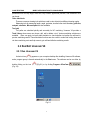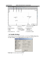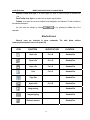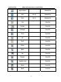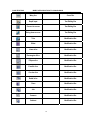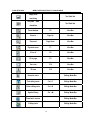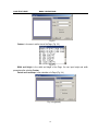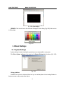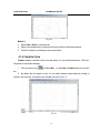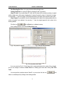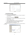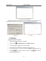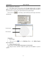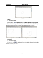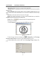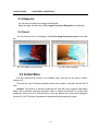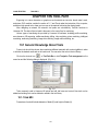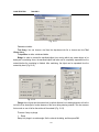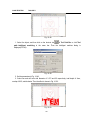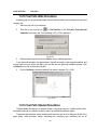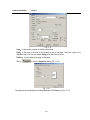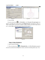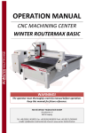
1
INTRODUCTION
“Ucancam V8 User Manual” was written specially for users of Ucancam V8 engraving
software. The content in this manual includes installation of the software, editing of text and
drawings, object operation, creation and simulation of tool paths, etc.
For the latest information about Ucancam software, please visit our website
www.ucancam.com or www.wt.com.cn.
COPYRIGHT DECLARATION
The copyright of this manual is owned by Beijing Wentai Technology Corporation and
copying of all or part of this manual by any organization or person is illegal.
“Ucancam” and “Wentai” are registered trademarks of Beijing Wentai Technology
Corporation. Other trademarks that appear in this manual are the property of their respective
holders.
“Ucancam V8 User Manual” is provided for users of Ucancam V8 software and gives a
detailed instruction about installation and operations of Ucancam V8 software.
Ucancam V8 has powerful functions and convenient interfaces. It has been widely used in
such fields as advertisements, mould-making, seal-making, sign-making, gift-manufacturing,
decoration, art works, woodworking, etc.
There are twelve chapters in this manual, including software installation, basic operations,
shape drawing, object operations, shape editing, text editing, node editing, tool paths, etc.
Contents
CHAPTER ONE SYSTEM REQURIRMENTS & INSTALLATION .............................. 1
1.1 System Requirements ............................................................................... 1
1.2 Installation of Ucancam V8 ........................................................................ 1
CHAPTER TWO BRIEF INTRODUCTION TO UCANCAM V8.................................. 6
2.1 Brief Introduction.......................................................................................... 6
2.1.1 Application......................................................................................... 6
2.1.2 Features............................................................................................ 6
2.2 Run/Exit Ucancam V8 .................................................................................. 7
2.2.1 Run Ucancam V8 ............................................................................... 7
2.2.2 Exit Ucancam V8................................................................................ 8
2.3 Interface...................................................................................................... 9
2.3.1 Standard Interface.............................................................................. 9
2.3.2 Panel Interface................................................................................. 10
2.4 ToolBar Settings..........................................................................................11
CHAPTER THREE BASIC OPERATIONS......................................................... 22
3.1 File Operation............................................................................................ 22
3.1.1 Open A File...................................................................................... 22
3.1.2 Create A New File ............................................................................ 22
3.1.3 Save A File ...................................................................................... 24
3.1.4 Import File ....................................................................................... 25
3.1.5 Export File ....................................................................................... 26
3.2 Viewing Tools ............................................................................................ 26
3.2.1 Zoom Window.................................................................................. 26
3.2.2 Zoom In........................................................................................... 27
3.2.3 Zoom Out ........................................................................................ 27
3.2.4 Dynamic Zoom................................................................................. 28
3.2.5 Fit To All .......................................................................................... 29
3.2.6 Fit To Page ...................................................................................... 30
3.2.7 Pan View......................................................................................... 30
3.2.8 3D View........................................................................................... 31
3.2.9 Filled Display ................................................................................... 34
3.3 Basic Settings............................................................................................ 35
3.3.1 System Settings ............................................................................... 35
3.3.2 Snap Function.................................................................................. 41
3.4 Other Tools................................................................................................ 43
3.4.1 Show/Hide....................................................................................... 43
3.4.2 Lock/Unlock..................................................................................... 43
3.4.3 Redraw ........................................................................................... 44
3.4.4 Measuring Tools............................................................................... 45
3.4.5 Calculator, Notepad & Microsoft Paint ................................................ 48
3.4.6 Help ................................................................................................ 49
3.4.7 About Ucancam................................................................................ 49
CHAPTER FOUR DRAWING SHAPES ............................................................ 50
4.1 Create simple shapes................................................................................. 50
4.1.1 Line ................................................................................................ 50
4.1.2 Arc .................................................................................................. 52
4.1.3 Circle .............................................................................................. 54
4.1.4 Ellipse ............................................................................................. 55
4.1.5 Spline.............................................................................................. 55
4.1.6 Combine Curve................................................................................ 56
4.1.7 Points.............................................................................................. 57
4.1.8 Rectangles ...................................................................................... 57
4.1.9 Star................................................................................................. 59
4.1.10 Regular Polygon............................................................................. 60
4.1.11 Arrow............................................................................................. 61
4.1.12 Spiral ............................................................................................ 61
4.1.13 Wavy line....................................................................................... 63
4.1.14 Hand Draw .................................................................................... 65
4.1.15 Bounding Box ................................................................................ 65
4.2 Symbol Library........................................................................................... 66
4.2.1 Show/Hide Symbol Library ................................................................ 66
4.2.2 Contents in Symbol Library ............................................................... 67
4.2.3 Selecting A Symbol........................................................................... 67
4.2.4 My Library ....................................................................................... 68
CHAPTER FIVE OBJECT OPERATION ........................................................... 69
5.1 Select An Object ........................................................................................ 69
5.1.1 Select With Mouse ........................................................................... 69
5.1.2 Select By Menu Command................................................................ 72
5.2 Transform Operation .................................................................................. 74
5.2.1 Move............................................................................................... 74
5.2.2 Scaling ............................................................................................ 75
5.2.3 Locate............................................................................................. 78
5.2.4 Object Rotation ................................................................................ 78
5.2.4 Mirror .............................................................................................. 82
5.2.5 Shear .............................................................................................. 85
5.2.6 Arc Fit ............................................................................................. 86
5.3 Align ......................................................................................................... 87
5.3.1 To Align An Object ............................................................................ 87
5.3.2 Vertical aligning & Horizontal aligning................................................. 90
5.3.3 Space ............................................................................................. 91
5.3.4 Make Same Size.............................................................................. 93
5.4 Perspective Distortion................................................................................. 94
5.5 Envelop Distortion...................................................................................... 95
5.6 Push and Pull Distortion ............................................................................. 97
5.7 Twist Distortion .......................................................................................... 98
5.8 Auto Nesting.............................................................................................. 99
5.9 Interactive Nesting ................................................................................... 101
5.10 Cancel & Repeat.................................................................................... 102
5.10.1 Cancel......................................................................................... 102
5.10.2 Repeat ........................................................................................ 102
CHAPTER SIX GRAPH EDITING.................................................................. 103
6.1 Copy, Paste, Cut...................................................................................... 103
6.2 Delete ..................................................................................................... 103
6.3 Trim ........................................................................................................ 104
6.4 Offset...................................................................................................... 105
6.5 Expand ................................................................................................... 107
6.6 Close ...................................................................................................... 107
6.7 Direction ................................................................................................. 109
6.8 Delete overlay loop ...................................................................................110
6.9 Slice ........................................................................................................111
6.9.1 Simple Slice....................................................................................111
6.9.2 Complex Slice.................................................................................112
6.10 Divide ....................................................................................................115
6.11 Boolean Operation ..................................................................................115
6.12 Duplication .............................................................................................118
6.13 Group & Ungroup................................................................................... 126
6.14 Block..................................................................................................... 126
6.15 Object Properties ................................................................................... 126
CHAPTER SEVEN TEXT EDITING................................................................ 129
7.1 Text Input ................................................................................................ 129
7.1.1 Rapid Input.................................................................................... 129
7.1.2 Editing Input .................................................................................. 130
7.2 Text Editing.............................................................................................. 130
7.2.1 Font Selection................................................................................ 130
7.2.2 Character Height & Width ............................................................... 131
7.2.3 Overstriking ................................................................................... 131
7.2.4 Incline ........................................................................................... 132
7.2.5 Vertical Text Flow ........................................................................... 132
7.2.6 Character Space & Line Space........................................................ 132
7.2.7 Align.............................................................................................. 133
7.2.8 Text Rotate .................................................................................... 134
7.2.9 Base Height................................................................................... 134
7.3 Text Along A Curve ................................................................................... 135
7.4 Hollow Character ..................................................................................... 138
7.5 Convert To Curves ................................................................................... 139
7.6 Serial Number Text................................................................................... 141
7.7 Text Symbol............................................................................................. 143
7.8 Replace .................................................................................................. 143
7.9 Single Stroke........................................................................................... 144
7.10
Text in a closed shape ..................................................................... 144
CHAPTER EIGHT NODE EDIT..................................................................... 145
8.1 Node Selection And Move......................................................................... 145
8.2 Add & Delete A Node................................................................................ 145
8.3 Cusping & Smooth ................................................................................... 147
8.4 Symmetry................................................................................................ 148
8.5 Node Align............................................................................................... 148
8.6 Convert To Line & Convert To Curve .......................................................... 149
8.7 Disconnect & Connect .............................................................................. 150
8.8 Close ...................................................................................................... 151
8.9 Start point ............................................................................................... 151
8.10 Auto Remove Points............................................................................... 152
8.11 Fillet ...................................................................................................... 152
8.12 Chamfer ................................................................................................ 153
8.13 Vertical.................................................................................................. 154
CHAPTER NINE ADDITIONAL OPERATIONS................................................. 155
9.1 Image Processing .................................................................................... 155
9.1.1 Image Scanning ............................................................................. 155
9.1.2 Adjust Brightness ........................................................................... 155
9.1.3 Adjust Contrast .............................................................................. 156
9.1.4 Convert Into Grayscale Image ......................................................... 156
9.1.5 Image Tracing................................................................................ 157
9.1.6 Image Stripping.............................................................................. 160
9.1.7 Threshold ...................................................................................... 161
9.1.8 Despeckle ..................................................................................... 162
9.1.9 Invert ............................................................................................ 162
9.2 Context Menu .......................................................................................... 162
9.3 Layer Edit................................................................................................ 164
CHAPTER TEN TOOL PATH ....................................................................... 166
10.1 General Knowledge About Tools .............................................................. 166
10.1.1 End Mill ....................................................................................... 166
10.1.2 Ball Nose..................................................................................... 167
10.1.3 Conical........................................................................................ 167
10.1.4 Tool Editing .................................................................................. 168
10.2 Profile Machining ................................................................................... 169
10.2.1 Parameters In Profile Machining .................................................... 169
10.2.2 Example ...................................................................................... 172
10.3 Area Clearance ...................................................................................... 173
10.4 3D Engraving......................................................................................... 175
10.5 Midline Machining .................................................................................. 177
10.6 Simple Drilling........................................................................................ 178
10.7 Region Drilling ....................................................................................... 180
10.8 Insert And Inlay ...................................................................................... 182
10.9 Prism Machining .................................................................................... 184
10.10 Intelligent Machining............................................................................. 185
10.11 Embossing Machining........................................................................... 187
10.12 Image AM/FM Machining ...................................................................... 188
10.13 Image Relief Machining ........................................................................ 189
10.14 Tool Path Sequence ............................................................................. 191
10.15 Tool path edit ....................................................................................... 192
10.16 Tool Path Transform ............................................................................. 194
10.17 Tool Path Output .................................................................................. 195
10.18 Tool Path Walk Simulation..................................................................... 198
10.19 Tool Path Shaded Simulation................................................................. 198
10.20 Tool Path Panel.................................................................................... 199
10.21 Group Toolpath .................................................................................... 200
CHAPTER ELEVEN OUTPUT ...................................................................... 202
11.1 Print ...................................................................................................... 202
11.1.1 Printer Installation......................................................................... 202
11.1.2 Printer Setting .............................................................................. 203
11.1.3 Printing A File ............................................................................... 205
CHAPTER TWELVE CASES........................................................................ 208
Case 1. Profile Machining............................................................................... 208
Case 2. Area Clearance ................................................................................. 210
Case 3. 3D Engraving.................................................................................... 214
Case 4. Midline Machining ............................................................................. 216
Case 5. Simple Drilling................................................................................... 218
Case 6. Insert And Inlay ................................................................................. 219
Case 7. Prism Machining ............................................................................... 221
Case 8. Intelligent Machining....................................................................... 223
Case 9. Embossing Machining .................................................................... 228
Case 10. Image FM/AM Machining ................................................................. 229
Case 11. Image Relief Machining.................................................................... 231
CHAPTER THIRTEEN WAVE BOARD ........................................................... 234
13.1 Texture.................................................................................................. 234
13.2 Straight Texture...................................................................................... 237
13.3 Curvilinear texture .................................................................................. 239
13.4 Wave .................................................................................................... 241
13.5 Silk Texture............................................................................................ 243
13.6 Texture Trimming ................................................................................... 244
CHAPTER ONE
SYSTEM REQURIRMENTS & INSTALLATION
CHAPTER ONE SYSTEM REQURIRMENTS &
INSTALLATION
1.1
System Requirements
Operation system: Windows2000/XP
CPU: Intel Pentium II, 300 or above, or same-level CPU, (preferable P4 2.4G or above)
RAM: 128MB or above, preferable 256MB
Hard disk: 500M
Monitor display: resolution 800ⅹ600, 256 colors, preferable 1024ⅹ768, true color
CD drive: CD-ROM/DVD driver
Port: available with Mouse port and USB2.0 port
1.2
Installation of Ucancam V8
Don’t insert the USB dongle into the USB port of your computer before installation. To install your
program and the USB dongle, please follow the procedures step by step.
1. Put the installation disk into the CD-ROM driver.
2. Run the file wtSetup.exe in the disk.
3. The initialization interface is shown after running the program. See Fig.1-1.
Fig. 1-1
4. Then the welcoming dialog is shown (Fig.1-2). It is suggested to close other running
programs during installation of this software to avoid incorrect installation. (Press Alt +Tab to
switch among programs.)
1
CHAPTER ONE
SYSTEM REQURIRMENTS & INSTALLATION
Fig.1-2
5. Click Next, and the License Agreement dialog is shown. (Fig.1-3) Please read it carefully
as this program is protected by copyright law, and any copying or spreading of the program
without authorization from Wentai Technology Co., Ltd is subject to civil and criminal sanction.
Click Yes to continue installation, and click No to exit installation.
Fig. 1-3
6. Click Yes, and Choose Destination Location dialog is displayed. Click Next if you want to
install the software in the default path (Fig.1-4).
Fig. 1-4
Click Browse if you want to change the installation path. Click OK to continue.
2
CHAPTER ONE
SYSTEM REQURIRMENTS & INSTALLATION
Fig.1-5
7. The program then asks whether you want to creat a shortcut icon of Ucancam V8 on the
desktop. (Fig.1-6). It is suggested to select Yes.
Fig.1-6
8. Click Next, and Start Copying Files dialog (Fig.1-7) is shown. The selected installation path
and file are shown in the dialog. Click Back if you want to change the path and file.
Fig.1-7
9. Click Next to start copying files. (Fig.1-8)
3
CHAPTER ONE
SYSTEM REQURIRMENTS & INSTALLATION
Fig.1-8
10. After copying the file, the installation of USB dongle driver begins automatically.
Fig.1-9
11. The installation of USB dongle begins. (Fig.1-10)
Fig.1-10
12. After the installation of USB driver, the following dialog displays to indicate that the installation
has been completed. (Fig.1-11)
4
CHAPTER ONE
SYSTEM REQURIRMENTS & INSTALLATION
Fig.1-11
13.Click Finish and the dialog Setup Complete displays. (Fig.1-12)
Fig.1-12
14. Click Finish to end installation.
An icon
is formed on desktop.
After confirming that the USB port of your PC is in normal working order, insert the USB dongle
into the USB port of your computer, or connect the USB dongle with the computer through USB cable.
You can now work with Ucancam V8.
5
CHAPTER TWO
BRIEF INTRODUCTION TO UCANCAM V8
CHAPTER TWO BRIEF INTRODUCTION TO
UCANCAM V8
2.1 Brief Introduction
2.1.1 Application
Ucancam V8, a special application software in CAD (Computer-Aided Design) and CAM
(Computer-Aided Manufacturing), is widely used in such areas as advertisements, seal-making,
sign-making, gift manufacturing, decoration, art design, woodworking and mold-manufacturing.
2.1.2 Features
Two types of interface
Both the new interface and the original 2000/2002 interface are available for users to choose
according to your habits.
Node editing
Functions in node editing include: add, delete, disconnect, connect, close, convert to line, convert
to curve, cusping, smooth, symmetry, node align, start point, auto remove points, fillet, chamfer, and
vertical.
Text Editing
Text can be rotated, scaled, moved, sheared, arranged along curves, etc. and they can be edited
again in text edit mode after these transformations. Besides, text input in a frame is also available, with
automatic line feed.
Serial number text
This function is used with making some designs of serial number texts.
Accurate drawing
Accurate drawing is made easy by means of keyboard input. Feature points such as end points,
midpoints, intersection points, perpendicular foot, and tangent points can be snapped.
Editing Tools
Various Editing Tools are provided, including trim, delete, offset, divide, close, simple slice,
complex slice, Boolean operation and duplication. Geometrical-shape-transforming tools include
move, rotate, scale, mirror, shear, perspective distortion, envelop distortion, twist distortion, push and
pull distortion and auto nesting.
Image tracing
Images in various formats can be imported, converted, and stripped. Image tracing is available
with Ucancam V8 in order to extract contour. Angle degrees can be adjusted, and accurate tracing
6
CHAPTER TWO
BRIEF INTRODUCTION TO UCANCAM V8
parameters such as cusp angle, trace error, fairy number, approximal precision, and threshold of line
can be set.
Other aided tools
There are numerous viewing tools which are used to view objects from different viewing angles.
Measuring tools for measuring length, angle, perimeter, size and other tools like ruler, guide line,
notepad, calculator, Microsoft paint are also available.
Tool path
Tool paths are calculated quickly and accurately for NC machining. Ucancam V8 provides a
Tools Library where users can choose, edit, add or delete a tool. Various machining solutions are
available. Users can apply tool path walk simulation to check whether tool paths are valid and to
preview machining results. These simulation functions are also useful to reduce trial cutting times and
cut down machining costs and help users to get valid and effective machining results.
2.2 Run/Exit Ucancam V8
2.2.1 Run Ucancam V8
A shortcut icon
appears on your computer desktop after installing Ucancam V8 software,
and a program group is formed automatically in the Start menu. The software can be run either by
double clicking on the icon
(Fig.2-1) or by clicking Program->UCanCam->
(Fig. 2-2)
Fig. 2-1
7
.
CHAPTER TWO
BRIEF INTRODUCTION TO UCANCAM V8
Fig. 2-2
The Page Size dialog displays after starting the software. (Fig. 2-3) Set the page size, and click
on OK or press the Enter key to enter Ucancam V8 software.
Fig. 2-3
REMARK: Refer to 3.3.1 of Chapter three to see how to set the Page Size parameters.
2.2.2 Exit Ucancam V8
Four ways to exit the program.
Click the button
on the upper right corner of the window.
Click File->Exit.
Press the shortcut key Alt+F4
in the corner of the window
Double click on the icon
A dialog appears to ask if you want to save the file that you haven’t saved. (Fig 2-4)
8
CHAPTER TWO
BRIEF INTRODUCTION TO UCANCAM V8
Fig. 2-4
2.3 Interface
Both new Ucancam V8 interface and Wentai 2000/2002 interface are available for the users to
choose according to your habits.
2.3.1 Standard Interface
Standard interface refers to Wentai 2000/2002 interface, which is also the default interface of
Ucancam V8. (Fig. 2-5)
Fig. 2-5
A. Title bar: displays file name or software name on the left; on the right are minimize button
maximize/back button
and close button
,
.
B. Menu bar: includes File, Edit, View, Draw, Text, Modify, Transform, Align, Node, Help, and
Tool Path.
9
CHAPTER TWO
BRIEF INTRODUCTION TO UCANCAM V8
C. Standard Bar: displays icons of commonly used tools
D View Bar: displays icons of viewing tools.
E. Edit bar: displays icons of editing tools.
F. Edit mode tool bar: is for opening or closing tool bars and change editing modes.
G. Tool path: displays icons for tool path calculation.
H. Draw bar: displays icons for drawing simple shapes
I. Coordinates: are references to object positions.
J. Page: is the page size.
K. Drawing window: is the area for drawing.
L. Status bar: displays current operation status and parameters input.
M. Ruler: displays actual sizes of objects. It shows in the work interface in default setting.
REMARK. Click View->Rulers command to show or hide rulers.
N. X / Y Coordinates: Shows coordinates.
O. Show/Hide the Grids: Show or hide background Grids.
REMARK. Click View->Grids to show or hide background Grids.
P. Snap setting: Set the types of points to be snapped and control the show and close of the
function.
Q. Color: is for setting color.
R. Hide/Show: Show or hide tool paths.
REMARK. Click View->Tool path command to show or hide tool paths.
Move the mouse onto any shortcut button, names of shortcut buttons will be shown
automatically.
2.3.2 Panel Interface
Panel interface is another interface of Ucancam V8. With bars in tab form, this software is
operated easily and quickly as the interface layout is quite clear. (Fig. 2-6)
10
CHAPTER TWO
A. Title bar
D. Status switch bar
G. Page
J. Rulers
M. Snap shortcut icon
BRIEF INTRODUCTION TO UCANCAM V8
Fig. 2-6
B. Menu bar
C. Shortcut button bar
E. View tools bar
F. Coordinates axes
H. Drawing window
I. Status bar
K. X, Y coordinates
L. Show/Hide Grids
N. Color
O. Show/Hide tool paths
2.4 ToolBar Settings
To switch between the above two kinds of interface, you should open ToolBar settings dialog.
Click View->Toolbars, and the ToolBar Settings dialog displays. (Fig. ig.2-7)
Fig 2-7
Toolbar Style: is to select a style of the interface.
11
CHAPTER TWO
BRIEF INTRODUCTION TO UCANCAM V8
Standard Toolbar Icon Style: is to select Large Icon style or Small Icon style in standard tool
bar.
Panel Toolbar Icon Style: is to select an icon style in panel toolbar.
Toolbars: is to select one or more toolbars to be displayed in the interface. To hide a toolbar in
the interface, deselect it.
, or by pressing the Enter key in the
You can save the settings by clicking
keyboard.
Shortcut Icons
Shortcut icons are shortcuts to menu commands. The table below outlines
commonly-used shortcut icons in Ucancam V8.
ICON
FUNCTION
SHORTCUT KEY
LOCATION
Start a file
Ctrl + N
Standard Bar
Open a file
Ctrl + O
Standard Bar
Save a file
Ctrl + S
Standard Bar
Print
Ctrl + P
Standard Bar
Page Size
Standard Bar
Import a file
Ctrl + R
Standard Bar
Image tracing
Standard Bar
Image stripping
Standard Bar
Distance measure
Standard Bar
12
CHAPTER TWO
BRIEF INTRODUCTION TO UCANCAM V8
Angle measure
Standard Bar
Undo
Ctrl + Z
Standard Bar
Redo
Ctrl + Y
Standard Bar
Line
Curve Bar
Polyline
Curve Bar
Rectangle
Curve Bar
Circle
Curve Bar
Arc
Curve Bar
Point
Curve Bar
Ellipse
Curve Bar
Spline
Curve Bar
Star
Curve Bar
Polygon
Curve Bar
Combine curve
Curve Bar
Arrow
Curve Bar
Spiral
Curve Bar
13
CHAPTER TWO
BRIEF INTRODUCTION TO UCANCAM V8
Wavy line
Curve Bar
Rapid input
Text Editing Bar
Convert to curves
Text Editing Bar
String alone a curve
Text Editing Bar
Trim
Modification Bar
Offset
Modification Bar
Linear slice
Modification Bar
Rectangular Slice
Modification Bar
Ellipse slice
Modification Bar
Parallel slice
Modification Bar
Circular slice
Modification Bar
Radial slice
Modification Bar
Close
Modification Bar
Join
Modification Bar
Common
Modification Bar
Subtract
Modification Bar
14
CHAPTER TWO
BRIEF INTRODUCTION TO UCANCAM V8
Not common
Modification Bar
Group
Ctrl + G
Modification Bar
Ungroup
Ctrl + U
Modification Bar
Direction
Modification Bar
Divide
Modification Bar
Expand
Modification Bar
Duplication along a
Modification Bar
curve
Array duplication
Modification Bar
Duplication along a
Modification Bar
line
Duplication along a
Modification Bar
arc
Duplication along a
Modification Bar
spiral curve
Move
Transform Bar
Mouse
Transform Bar
Scale
Transform Bar
Horizontal mirror
Transform Bar
15
CHAPTER TWO
BRIEF INTRODUCTION TO UCANCAM V8
Vertical mirror
Transform Bar
Line mirror
Transform Bar
Shear
Transform Bar
Perspective
Transform Bar
distortion
Envelop distortion
Transform Bar
Push & Pull
Transform Bar
distortion
Twist distortion
Transform Bar
Auto nesting
Transform Bar
Align on left
Ctrl + Num4
Aligning Bar
Align on right
Ctrl + Num6
Aligning Bar
Align to top
Ctrl + Num8
Aligning Bar
Align to bottom
Ctrl + Num2
Aligning Bar
Align on center
Ctrl + Num5
Aligning Bar
Horizontal aligning
Alt + ,
Aligning Bar
Vertical aligning
Alt +.
Aligning Bar
Horizontal spacing
Alt + [
Aligning Bar
16
CHAPTER TWO
BRIEF INTRODUCTION TO UCANCAM V8
Vertical spacing
Alt + ]
Aligning Bar
Make same width
Ctrl + Alt + W
Aligning Bar
Make same height
Ctrl + Alt + H
Aligning Bar
Make same size
Ctrl + Alt + A
Aligning Bar
Add a node
Node Editing Bar
Delete a node
Node Editing Bar
Disconnect
Node Editing Bar
Connect
Node Editing Bar
Close
Node Editing Bar
Convert to line
Node Editing Bar
Convert to curve
Node Editing Bar
Cusping
Node Editing Bar
Smooth
Node Editing Bar
Symmetry
Node Editing Bar
Node align
Node Editing Bar
Start point
Node Editing Bar
17
CHAPTER TWO
BRIEF INTRODUCTION TO UCANCAM V8
Auto remove points
Node Editing Bar
Fillet
Node Editing Bar
Chamfer
Node Editing Bar
Vertical
Node Editing Bar
Tool management
Tool Path Bar
Tool path output
Tool Path Bar
Profile machining
Tool Path Bar
Area clearance
Tool Path Bar
3D engraving
Tool Path Bar
Midline machining
Tool Path Bar
Drilling
Tool Path Bar
Insert
Tool Path Bar
Inlay
Tool Path Bar
Prism machining
Tool Path Bar
Intelligent
Tool Path Bar
machining
Embossing
Tool Path Bar
machining
18
CHAPTER TWO
BRIEF INTRODUCTION TO UCANCAM V8
Image relief
Tool Path Bar
machining
Tool path
walk
Tool Path Bar
simulation
Zoom window
F6
View Bar
Zoom in
Page Up
View Bar
Zoom out
Page Down
View Bar
Dynamic zoom
F7
View Bar
Fit to all
F8
View Bar
Fit to page
F9
View Bar
Pan view
F10
View Bar
3D view
F12
View Bar
Selection tools
Editing Mode Bar
Text editing tools
Ctrl + T
Editing Mode Bar
Node editing tools
Ctrl + K
Editing Mode Bar
Symbol library
Ctrl + M
Editing Mode Bar
Draw basic vectors
Editing Mode Bar
Editing tools
Editing Mode Bar
19
CHAPTER TWO
BRIEF INTRODUCTION TO UCANCAM V8
Transform
Editing Mode Bar
Align
Editing Mode Bar
Tool path
Editing Mode Bar
Toolbars
Toolbars consist of commonly used commands.
Fig.2-8a
Editing Mode Bar
Fig.2-8b
Standard Bar
Fig. 2-8c
View Bar
Fig.2-8d
Curve Bar
Fig.2-8e
Fig. 2-8f
Fig.2-8g
Text Editing Bar
Node Editing Bar
Modification Bar
20
CHAPTER TWO
BRIEF INTRODUCTION TO UCANCAM V8
Fig.2-8h
Transform Bar
.
Fig.2-8i
Aligning Bar
Fig.2-8j
Tool Path Bar
21
CHAPTER THREE
BASIC OPERATIONS
CHAPTER THREE BASIC OPERATIONS
In this chapter, you will learn about the basic operations of Ucancam V8.
3.1 File Operation
3.1.1 Open A File
There are 3 ways to open a file:
Click on the icon
on Standard Bar
Click File->Open
Press Ctrl+O.
Then the Open dialog displays. (Fig. 3-1)
Fig. 3-1
You can choose the path of the file, or enter the file name after File Name. Select Preview to
preview contents of a selected file.
after selecting the file name to open the file.
Click
REMARK. The selected file can also be opened by double clicking the file or by pressing the
Enter key on the keyboard.
3.1.2 Create A New File
Any of the following three ways can be chosen to create a new file.
Click on the icon
on Standard Bar
Click File->New
Press Ctrl + N
Then the Page Size dialog displays. (Fig. 3-2)
22
CHAPTER THREE
BASIC OPERATIONS
Fig.3-2
Custom: is for users to set the size of the Page. (Fig. 3-3)
Fig. 3-3
Width and Height: is the width and height of the Page. You can input height and width
parameters after selecting Custom.
Portrait and Landscape: is the orientation of a Page. (Fig. 3-4)
Fig. 3-4a (portrait)
23
CHAPTER THREE
BASIC OPERATIONS
Fig. 3-4b (Landscape)
After selecting or setting a Page, click on
or press the Enter key to create a new
Page.
3.1.3 Save A File
There are three ways to save a file.
Click on the icon
on Standard Bar
Click File->Save.
Press Ctrl + S.
In case of creating a new file or changing the path of a file, press Ctrl +Shift +S or click
File->Save As. Then the dialog Save As is shown. (Fig.3-5)
Fig. 3-5
Users can select the saving path of the file in the pull down box Save As Type, and then input
the name of the file. Select Preview in the bottom right corner of the dialog to preview the file.
After selecting the saving path and name of the file, click on
key to save the file.
24
or press the Enter
CHAPTER THREE
BASIC OPERATIONS
3.1.4 Import File
Click File->Import File to import a file to the current page.
The following are file formats that is compatible by Ucancam V8. (Fig.3-6)
Fig.3-6
TXT file: ASCII text file.
BMP File: windows-bitmap, bitmap, Windows or OS/2 bitmap file.
DXF File: The Drawing Interchange Format (DXF) enables the interchange of drawings between
AutoCAD and other programs.
EPS File: Encapsulated PostScript (EPS) is a standard file format for importing and exporting
PostScript files.
JPEG File: JPEG is a file format created for storing still color images. It provides very good
compression, but does not uncompress exactly as it was.
PLT File: PLT (also HPGL) created by Hewlett-Packard is the standard language for printing line
drawings. HPGL is supported by many CAD, charting and word processing applications.
AI File: Adobe Illustrator file format
There are 3 ways to import a file:
Click on the icon
on Standard Bar.
Click File->Import file in the menu bar
Press Ctrl + R.
Then Import File dialog displays. (Fig. 3-7)
Fig. 3-7
The only difference between Import File dialog and Open dialog is that you can select other file
25
CHAPTER THREE
BASIC OPERATIONS
formats in Import File dialog. The file is opened after clicking on it and then clicking on
or pressing the Enter key.
REMARK: When you want to import a file whose format is not supported by this software, please
use other software such as windows paint and Photoshop to convert it to file formats compatible for
this software before importing the file.
3.1.5 Export File
You can save a file into other formats (e.g. DXF, PLT) compatible with other software. Choose
the objects to be saved and then click File->Export in the menu bar.
3.2 Viewing Tools
3.2.1 Zoom Window
Parts of a shape can be viewed closely through Zoom window. The following are three ways to
start Zoom window.
Click on the icon
on View Bar.
Click View->Zoom window in the menu bar.
Press the shortcut key F6.
Then the cursor changes into
. Hold the left mouse button and move the cursor to form a
view box; release the mouse button, then that part of the object is magnified.
Fig. 3-8 a (original view)
26
CHAPTER THREE
BASIC OPERATIONS
Fig. 3-8 b (form a view box)
Fig.3-8 c (Zoom window)
Click the right mouse button in the drawing window to resume the original object size.
3.2.2 Zoom In
The page can be magnified through Zoom in function.
There are three ways to start Zoom in operation.
Click the icon
on View Bar.
Click View->Zoom in on the menu bar.
Press the shortcut key Page Down.
The Page is magnified by two times after each operation. (Fig. 3-9)
Fig. 3-9a (original)
Fig. 3-9b (after zoom in operation)
3.2.3 Zoom Out
The page can be minified through Zoom out function. This can be achieved in any of the
following ways.
Click the icon
on View Bar.
27
CHAPTER THREE
BASIC OPERATIONS
Click View->Zoom out on the menu bar.
Press the shortcut key Page Up.
The Page is minified by half after each operation. (Fig 3-10)
Fig. 3-10a (original)
Fig. 3-10b (after Zoom out operation)
3.2.4 Dynamic Zoom
The page can be zoomed in or out through Dynamic zoom operation so that objects can be
viewed in different sizes. This can be achieved by any of the following means.
Click the icon
on View Bar.
Click View->Dynamic zoom on the menu bar.
Press the shortcut key F7.
Then the cursor changes into
. Press the left mouse button, and the page is zoomed in by
moving the mouse up, and is zoomed out by moving the mouse down. (Fig. 3-11)
Fig 3-11a (original)
28
CHAPTER THREE
BASIC OPERATIONS
Fig. 3-11b (after zooming in)
Fig. 3-11c (after zooming out)
Click the right mouse button to exit Dynamic zoom operation. The cursor changes into an arrow
and the Dynamic zooming effect remains.
REMARK: If you use 3D mouse, Dynamic zoom operation can be achieved by rolling the mouse
wheel. The page is zoomed in by rolling the mouse wheel forward and is zoomed out by rolling the
mouse wheel backward.
3.2.5 Fit To All
Selected objects can be displayed in the whole window through Fit to all function. First select the
object(s), and then select one of the following ways.
Click the icon
on View Bar.
Click View->Fit to all.
Press the shortcut key F8.
The effect is shown below.
Fig. 3-12a (select an object)
Fig. 3-12b (after Fit to all)
REMARK: If no objects are selected before enabling Fit to all operation, then all objects in the
drawing window will be displayed in the whole view window after Fit to all operation. The
following is an example when no object in Fig.3-17 is selected. (Fig.3-13)
29
CHAPTER THREE
BASIC OPERATIONS
Fig. 3-13
3.2.6 Fit To Page
Object position in the page can be viewed through Fit to page function.
There are 3 ways to start this function.
Click on the icon
on View Bar.
Click View->Fit to page on the menu bar.
Press the shortcut key F9.
The effect is shown below.
Fig 3-14a (original)
Fig. 3-14b (after Fit to page)
3.2.7 Pan View
The whole Page can be moved so that you can view different parts of the drawing. This can be
achieved through any of the following ways.
Click on the icon
on View Bar.
Click View->Pan view in the menu bar
Press the shortcut key F10.
30
CHAPTER THREE
BASIC OPERATIONS
Then the cursor changes into
, and move the mouse with left button pressed to move the
page. (Fig. 3-15)
Fig. 3-15a (original graph)
Fig. 3-15b (after Pan View)
Click on the right mouse button in the drawing window to stop the moving.
3.2.8 3D View
You can view objects in 3D view by 3D view function.
This can be achieved through any of the following ways.
Click on the icon
in View Bar.
Click View->3D view in the menu bar.
Press the shortcut key F12.
After clicking on
, the cursor changes into
, press the left mouse button to view the object
in 3D display. (Fig. 3-16)
Fig. 3-16a (original)
Fig. 3-16b (3D view)
In 3D view mode, click on the right mouse button to display the context menu. (Fig.3-17). Four
types of 3D view functions are available in context menu:Front view, left view, top view, and ISO
31
CHAPTER THREE
BASIC OPERATIONS
view. Next we are to illustrate these functions by taking area clearance tool path as an example. (Fig.
3-18)
Fig. 3-17 (context menu in 3D view mode)
Fig. 3-18a (a rectangle’s tool path)
Fig. 3-18 b (front view)
Fig. 3-18 c (left view)
Fig 3-18d (top view)
32
CHAPTER THREE
BASIC OPERATIONS
Fig. 3-18e (ISO view)
Seven viewing methods are provided in the context menu, including Zoom window, Zoom in,
Zoom out, Dynamic zoom, Pan View, Fit to all, Fit to page. Now let’s look at effects of these seven
view functions in 3D view mode. (Fig. 3-19)
Fig 3-19a (Zoom window in 3D view)
Fig. 3-19b (Zoom In in 3D view)
Fig. 3-19c (Zoom out in 3D view)
Fig. 3-19d (Fit to all in 3D view)
33
CHAPTER THREE
BASIC OPERATIONS
Fig. 3-19e (Fit to page in 3D view)
Fig. 3-19f (Pan View in 3D view)
Fig. 3-19g (Dynamic zoom in 3D view)
REMARK: In the 3D view mode, press key board arrow keys to move the page up, down, right
and left. Press X, Y, Z key to rotate the page along X ,Y ,Z axis respectively. During rotating, if Shift
key is pressed, rotation direction is anti-clockwise.
3.2.9 Filled Display
Selected objects can be filled with color through Filled display function. Select View->Filled
display to start the operation. (Fig.3-20)
Fig. 3-20a (original)
34
CHAPTER THREE
BASIC OPERATIONS
Fig. 3-20b (filled display)
REMARK: Click the color box in the status bar to display the color dialog. (Fig.3-25) Select a color
to fill the object.
Fig. 3-21
3.3 Basic Settings
3.3.1 System Settings
System settings is aimed at making the operations more customizable to every users.
Click View->System settings on the menu bar, the System Settings dialog is shown. (Fig. 3-22)
Fig. 3-22
Set up guidelines
Guidelines are vertical or horizontal lines that you can add anywhere in the drawing Window to
help you measure, align, and position objects.
35
CHAPTER THREE
BASIC OPERATIONS
You can display or hide the guidelines. You can also add, delete, move, and lock guidelines in the
drawing window. (Fig. 3-23)
Fig.3-23a put the mouse on the ruler
Fig. 3-23b guideline displays
After putting the cursor on the ruler, press and hold the left mouse and then drag the guide line to
the desired position. (Fig. 3-24) You can drag several guidelines by following the above steps.
Fig. 3-24
It is very difficult to drag the guideline to a specific position with the method above, so guideline
setting function is provided by Ucancam V8.
This function can be started by clicking View->System Settings on the menu bar. Click on
Guidelines. (Fig.3-25)
Fig. 3-25
First enter the value of the guideline coordinate, e.g.180, in the dialog. (Fig. 3-26)
36
CHAPTER THREE
BASIC OPERATIONS
.
Fig. 3-26
Then, select Horizontal or Vertical before clicking on
.
Then a guideline is
added in the working window. (Fig. 3-27)
Fig. 3-27
You can add more guidelines by repeating the steps above. (Fig.3-28). Click
the added guidelines are shown in the drawing window.
Fig. 3-28
Guidelines can also be deleted, modified or hidden.
There are three ways to delete guidelines.
37
, and
CHAPTER THREE
BASIC OPERATIONS
Click on the guideline and press the Delete key on the keyboard.
Put the cursor on the guideline, and when the cursor changes into
or
, drag the
guide line back onto the ruler.
Select the value of the guideline in Guidelines box, the value is covered in blue (see
Fig.3-27) and then click on
.
If you want to delete all horizontal and vertical guidelines, select the guidelines in Guidelines box
and click on
.
To modify a guideline, that is to change the position of a guideline, first select the value in the
Guidelines box, and click on
. Then input a new value, and the guideline position is
changed.
The guidelines not used can be hidden by clicking View->Guidelines show/hide in the menu bar
or by deleting “√” before Show Guidelines.
Grids setting
Grids are a series of intersecting lines superimposed on an object to help you align and position
objects accurately. You can display or hide grids at any time. You can have objects align automatically
with the gridlines. You can set up the grid by specifying values for the frequency, which is the number
of gridlines per unit of horizontal and vertical distance, or the spacing, which is the distance between
the grid lines. The style of grids can also be changed.
For more precise pixel editing at maximum zoom level, you can display a grid around each pixel.
Fig. 3-29
There are two kinds of grids in Ucancam V8 software: rectangular (Fig. 3-30) and radial (Fig.
3-31). The space of the rectangular grids can be adjusted by setting the horizontal and vertical spaces,
and spaces of the radial grids can be adjusted by setting the angle and space between every two
lines.
38
CHAPTER THREE
BASIC OPERATIONS
Fig. 3-30 Rectangular grids
Fig.3-31 Radial grids
The background grids can be changed by any of the following two ways.
Add or delete the “√”before Show grids;
on Status bar.
Click View->Grids; or click on the icon
General settings
General settings include arrow key increment step, auto save, curve accuracy, and
maximum angle of centerline.
39
CHAPTER THREE
BASIC OPERATIONS
Fig. 3-32
Arrow key increment step
By default, the move in X and Y direction is 1mm each time.
Rotate is for controlling the rotation of objects. Select an object, press the Ctrl key on the
keyboard, and press the left or right arrow keys on the keyboard to rotate objects. Anti-clockwise
rotation is achieved by pressing the left arrow key and clockwise rotation is achieved by pressing the
right arrow key.
Auto Save
Auto save ensures that no data will be lost accidentally. Objects are saved in a file named
backup.ucc and the file is in Ucancam Install directory. You can set the auto save intervals by typing
in a value in Auto Save box.
Curve Accuracy
Show
Displayed curves are more accurate if smaller values are entered in Show box, but the accuracy
has no effect on tool path.
Machining
If value of machining accuracy is smaller, tool paths calculated and the machining result are
better.
Snap
Users can set the mouse snap accuracy. If the distance between the cursor and a point is less
than the snap accuracy after snap function starts, the cursor changes into
and the point is
snapped.
Maximum angle of centerline
Maximum angle of centerline is the angle formed by any two adjacent centerlines. The
centerlines can be formed only when the angle exceeds the defined value. This setting is also useful
when snapping and processing midlines.
As can be seen in Fig. 3-33, when the defined angle is 30 degrees, the centerline with an angle
of 45 degrees is shown as below (Fig. 3-34). But if the pre-defined angle is above 45 degrees, then the
40
CHAPTER THREE
BASIC OPERATIONS
effect is not shown.
Fig 3-33
Fig. 3-34
Default settings
The default parameters can be set by clicking on
.
REMARK: It is recommended not to change the parameters unless there are special
requirements.
3.3.2 Snap Function
Snap function is very helpful when we need to find perpendiculars, tangents, center lines, etc. We
use the snap function to find the end points, adjacent points, midpoints, center of a circle, intersection
points, perpendicular points, tangent points, quartiles and grids.
The following dialog is displayed after selecting View->Snap Settings command or clicking on
in the right corner of the status bar. (Fig. 3-35) Click again, and the dialog is hidden
automatically.
Fig. 3-35
The feature points must be selected first, otherwise the snap function will not work. Next we are
going to see two examples to introduce the snap function.
Example 1
41
CHAPTER THREE
BASIC OPERATIONS
Now we want to draw a line with the rectangle’s one side’s mid point as an end point of the line.
The following is an example.
1. First draw a rectangle.
2. Then click on
in the lower right corner of the screen. The feature point boxes are
displayed in the bottom of the screen. (See below.)
3. Tick the box Mid.
4. Put one end of the line outside the rectangle, and drag the mouse onto the side of the rectangle.
When the cursor changes into “
”, the midpoint of one side of the rectangle is found. (Fig. 3-36)
5. Click the left mouse button, and the end point of the line is fixed in the mid point of the
rectangle’s side.
Fig. 3-36
Example 2
Draw a circle, and snap the quartile point in the same way as in example 1. The result is shown in
Fig. 3-37.
Fig. 3-37
REMARK: The above points are not necessarily fit for all curves. For example, tangency points
are applied to curves like arcs and splines, but not to rectangles; perpendicular is applied to line and
42
CHAPTER THREE
BASIC OPERATIONS
rectangle but not to circle.
3.4 Other Tools
3.4.1 Show/Hide
This function is to avoid the influences of intersected or adjacent objects when drawing or editing
an object.
1. Select an object.
2. Select Edit->Hide object on the menu bar.
Then the selected object is hidden. (Fig. 3-38b)
Fig. 3-38a
Fig. 3-38b
The hidden object reappears after clicking Edit->Show object. (Fig. 3-39)
Fig. 3-39
REMARK: This function is very useful when calculating tool paths. (Please refer to Tool Path in
Chapter Ten.)
3.4.2 Lock/Unlock
When Lock function is enabled, an object’s position, shape and size are preserved.
43
CHAPTER THREE
BASIC OPERATIONS
To lock an object
1. Select the object to be locked.
2. Click Edit->Lock/unlock on the menu bar. (Fig. 3-40)
Fig. 3-40a (click on lock/unlock)
Fig. 3-40b (the rectangle is locked)
To unlock an object
1. Select the object.
2. Click Edit->Lock/unlock on the menu bar. (Fig. 3-41)
Fig. 3-41a (select the locked rectangle)
Fig. 3-41b (unlock the rectangle)
3.4.3 Redraw
You can improve the appearance of an object by removing unwanted speckles on it. You can
enable this function by clicking View->Redraw on the menu bar or by pressing F5 on the keyboard.
(Fig. 3-42)
44
CHAPTER THREE
BASIC OPERATIONS
Fig. 3-42a (dotted lines are left in the lower right corner)
Fig 3-42b (after redraw)
3.4.4 Measuring Tools
Such functions as Distance measure, Angle measure, Perimeter measure, Area measure are
available in Ucancam V8.
Distance measure
on Standard Bar, or click Help->Distance measure on the menu
1.
Click on the icon
2.
The cursor changes into
3.
Select the starting point and end point with the mouse.
bar.
.
45
CHAPTER THREE
BASIC OPERATIONS
Fig.3-43
REMARK: In case of measuring horizontal or vertical distances, press Shift key in the keyboard,
and drag the mouse to move on horizontal or vertical direction.
Angle measure
on Standard Bar, or click Help->Angle measure on the menu bar.
1.
Click the icon
2.
When the cursor changes into
, click on the angle peak and then move the cursor along
one side of the angle. Click again.
3. Continue to move the cursor until the cursor reaches the other side of the angle. Click the left
mouse button again.
4. Then angle degree is shown. (Fig. 3-44)
Fig. 3-44
Perimeter measure
1. Click Help->Perimeter measure on the menu bar.
2.
The cursor changes into
.
46
CHAPTER THREE
3.
Move
BASIC OPERATIONS
onto the shape to be measured. (Fig. 3-45)
4. When the shape outline changes into dotted blue lines, click the left mouse button.
The value of the perimeter of the shape is shown in the status bar in the lower left corner of the
screen.
Fig. 3-45
Area measure
Area measure is for measuring the size of a shape.
1. Click Help->Area measure in the menu bar.
2.
The cursor changes into
3.
Move
.
onto the shape to be measured.
4. When the shape is changed into a dotted blue line, click the left mouse button. (Fig. 3-46)
5. The value of the size of the shape is shown in the status bar in the lower left corner of the
status bar.
Fig. 3-46
The Maximum Inscribed Circle
47
CHAPTER THREE
BASIC OPERATIONS
1. Click Help-> The maximum inscribed circle on the menu bar, or press “Alt +5” on the keypad.
2. The cursor changes to
.
3. Move the cursor to the graph to be measured, and the graph is changed into a dotted blue line.
4. Press the mouse left button.
5. The measured value is displayed in the status bar.
3.4.5 Calculator, Notepad & Microsoft Paint
Calculator, Notepad and Microsoft paint are available in Ucancam V8 to make your operation
easier.
Calculator
Calculator can be enabled after clicking Help->Calculator on the menu bar. (Fig. 3-47)
Notepad
Notepad can be enabled after clicking Help->Notepad. (Fig. 3-48)
Microsoft paint
Microsoft paint can be enabled after clicking Help->Microsoft paint on the menu bar. (Fig.3-49)
Fig. 3-47
Fig. 3-48
Fig. 3-49
48
CHAPTER THREE
BASIC OPERATIONS
3.4.6 Help
Ucancam V8 offers a variety of ways to help you learn the application.
User manual
On line technical support
Help available in the software
To use Help
1. Click Help->Help in the menu bar.
2. The Help dialog displays. (Fig. 3-50)
Fig. 3-50
3.4.7 About Ucancam
The information about Ucancam V8 software is available for users to know more about Ucancam
V8.
1.
2.
Click Help->About Ucancam on the menu bar.
The dialog About Ucancam is displayed. (Fig. 3-51)
Fig 3-51
The dialog is closed by clicking
or pressing the Enter key on the keyboard.
49
CHAPTER FOUR
DRAWING SHAPES
CHAPTER FOUR DRAWING SHAPES
Line, arc, circle, ellipse, Bezier curve, wavy line, combine curve, points, rectangle, star, spiral and
regular polygons can be created and drawn in Ucancam V8.
The following are the main features in Ucancam V8.
Point coordinates can be numerically input.
Automatically snap end points, midpoints, intersection points, tangency points, and other
feature points.
Editing functions such as delete, offset, cut and trim, and Boolean operation functions such
as join, common, not common and subtract are available.
Transformation tools like move, rotate, mirror, scale and aligning tools such as horizontal
spacing, and make the same size are available.
Useful node editing tools.
This chapter is devoted to a general introduction of creating and drawing geometrical shapes and
using the symbol library. Objects with various shapes can be created after reading this chapter.
4.1 Create simple shapes
You can create simple shapes by entering coordinates. The origin (0,0) is in the center of the
interface.
Absolute coordinate: is to fix a point at a certain position by entering two values of X and Y axis
coordinates.
Relative coordinate: is to fix a point at a certain position by entering two values of X and Y axis
coordinates, with another point as the origin. The two values represent the distance of the new point
from the other point on X and Y axis.
4.1.1 Line
1. Line
Method 1
on Curve Bar, or click Draw ->Line->Line in the menu bar.
1.
Click the shortcut icon
2.
3.
4.
5.
The words Start of Line are shown in the status bar in the lower left corner.
Input a point’s coordinates value, e.g. 10,10, and press Enter key.
Input a point’s coordinates value after the screen displays end of line in the status bar.
Press the Enter key and a line is created.
50
CHAPTER FOUR
DRAWING SHAPES
Fig. 4-1
Method 2
1. Click Draw ->Line->Line in the menu bar.
2. Click in the drawing window to select the position of the starting point and end point of the
line.
3. You can reshape the line by transformation tools, such as moving, rotating, scaling etc.
Detailed introduction to these transformations will be given in the following chapter.
REMARK: Horizontal line and vertical line can be drawn by pressing the Shift key while moving
the cursor. A coordinate (X, Y) represents a point position, “X ” and “Y” are separated by a comma. In
Ucancam V8, you will need to input coordinate value in many operation.
When you need to draw a precision curve, it is suggested to use method 1 to input point’s
coordinates.
2. Polyline
Method 1
on Curve Bar, or click Draw->Line->Polyline in the menu
1.
Click the shortcut icon
2.
3.
Input polyline’s points respectively according to prompt instructions in the status bar.
Click the right mouse button to finish this operation and a polyline is created.
bar.
Fig. 4-2
51
CHAPTER FOUR
DRAWING SHAPES
Method 2
You can also just click in the drawing window to define the points of the polyline. You can end the
operation by clicking the right mouse button.
REMARK: Horizontal or vertical polylines can be drawn by pressing the Shift key while moving
the cursor.
3. Double Polyline
You can draw two parallel lines at a time with Double Polyline.
Fig. 4-3
4.1.2 Arc
1. Three-points
Method 1
on Curve Bar, or click Draw->Arc-> 3 Points on the menu
1.
Click the shortcut icon
2.
Input three points coordinates respectively in the status bar and press Enter.
bar.
Fig. 4-4
Method 2
1. Click Draw->Arc-> 3 Points on the menu bar.
2. Click in the drawing window to fix the position of the three points of the arc.
2. Center, start, end
52
CHAPTER FOUR
DRAWING SHAPES
1. Click Draw->Arc->Center, start, end in the menu bar.
2. Input the coordinate in the status bar and press Enter.
Remark: Center means the center of the circle the arc is on.
Fig. 4-5
Drawing an arc by center, start, end command is the same as drawing a 3-point arc, and the
only difference is that the starting point is different. In Center, start, end, the first point is the center of
the circle, the second point is the starting point of the arc, and the third point is the end point of the arc.
3. Start, end, direction
When applying this method while drawing an arc, the first point is the starting point of the arc, the
second point is the end point, and direction is the end point tangent.
4. Start, end, radius
The first point is the starting point of the arc, the second point is the end point of the arc and the
third step is to define the radius of the circle the arc is on.
After inputting the values in the status bar, press Enter key to validate the operation.
5. Tangential Arc
You can draw a arc by a tangent. Follow the steps below.
1. Draw a circle.
2. Click Draw->Arc->Tangential Arc in the menu bar.
3. The cursor becomes a pen. Drag the pen to the circle, and a blue line appears. (Fig. 4-6)
4. Choose the position you want to put the arc, and then click the mouse button.
5. Then drag the pen to a specific position according to the radius of the arc to be created. Then
click again to fix the radius.
6. Move the pen to define the arc length, and then click the mouse button to finish.
53
CHAPTER FOUR
DRAWING SHAPES
Fig. 4-6
4.1.3 Circle
Method 1
1.
Click the shortcut icon
2.
3.
4.
5.
6.
The words Center of circle are displayed in the status bar.
Input a coordinates value, e.g.10,10.
Press the Enter key, and the position of the center of the circle is fixed.
Input the value of the radius of the circle.
Press Enter key, and a circle is drawn.
in Curve Bar, or click Draw-> Circle on the menu bar.
Fig. 4-7
Method 2
1. Click Draw-> Circle on the menu bar.
2. Click in the drawing window to select a point as the center of the circle.
3. Move the mouse to define the radius of the circle.
4. Click the left mouse button to finish drawing the circle.
54
CHAPTER FOUR
DRAWING SHAPES
4.1.4 Ellipse
Method 1
1.
Click the shortcut icon
2.
3.
4.
5.
6.
Select Draw->Ellipse on the menu bar.
The words Center of ellipse are shown in the status bar.
Input a coordinate value to fix the position of the center of the ellipse.
Enter a coordinate value to define the end point of the first axis of the ellipse.
Enter the coordinate value of the length of the other axis of the ellipse.
on Curve Bar.
Fig. 4-8
Method 2
1. Select Draw->Ellipse on the menu bar.
2. Select a point as the center of the ellipse by clicking in the drawing window.
3. Click in another position to fix one axis of the ellipse.
4. Click in a third point to define the radius of another axis of the ellipse.
4.1.5 Spline
Method 1
1.
Click the shortcut icon
on Curve Bar, or click Draw->Spline on the menu bar.
2.
3.
Input coordinate value respectively by following the instructions in the status bar,.
Finish the operation by clicking the right mouse button in the drawing window.
55
CHAPTER FOUR
DRAWING SHAPES
Fig. 4-9
Method 2
1. Select Draw->Spline on the menu bar.
2. Select points respectively by clicking the left mouse button in the drawing window.
3. Finish this operation by clicking the right mouse button.
4.1.6 Combine Curve
Combine curve is consisted of lines, arcs and splines. You can switch between line, 3 Point Arc,
Tangential Arc and Spline drawings.
1.
Click the shortcut icon
on Curve Bar,or click Draw->Combine curve on the menu
bar.
2. By default, the first shape is a line. You can switch between these shapes by clicking on
options in the status bar. A combine curve example is shown in Fig. 4-11.
F 4-10
56
CHAPTER FOUR
DRAWING SHAPES
Fig. 4-11
4.1.7 Points
Method 1
Click the icon
on Curve Bar, or click Draw->Point on the menu bar.
Several points can be drawn at a time by inputting the coordinates of the points by following
instructions in the status bar.
Method 2: Click Draw->Point on the menu bar, or select points by clicking in the drawing
window.
4.1.8 Rectangles
1. Rectangle
Method 1
1. Click the shortcut icon
on Curve Bar, or click Draw->Rectangle->Rectangle in the
menu bar.
2. Input coordinate value by following instructions in the status bar.
57
CHAPTER FOUR
DRAWING SHAPES
Fig. 4-12
Method 2
1. Click Draw->Rectangle->Rectangle on the menu bar.
2. Select two points by clicking in the drawing window.
3. Finish this operation by clicking the right mouse button.
2. Fillet rectangle
There are two ways to draw a fillet rectangle:
Method 1
1. Click Draw->Rectangle ->Fillet Rectangle on the menu bar.
2. Input two corner points’ coordinates and radius of fillet.
Fig. 4-13
Fig. 4-14
Method 2
1. Click Draw->Rectangle ->Fillet Rectangle on the menu bar.
2. Select two points as two of the rectangle’ corners by clicking in the drawing window.
3. Get the correct radius by moving the mouse and clicking the left mouse button.
REMARK: When using Method 1 to create a Fillet rectangle, you can move the cursor to get two
different results.
58
CHAPTER FOUR
DRAWING SHAPES
3. Chamfer rectangle
Method 1
1. Click Draw->Rectangle->Chamfer rectangle in the menu bar.
2. Input points’ coordinates and chamfer value.
Fig. 4-15
Fig. 4-16
Method 2
1. Click Draw->Rectangle->Chamfer rectangle in the menu bar.
2. Select two points as a rectangle’s corners by clicking in the drawing window.
3. Get a chamfer distance by clicking in the drawing window.
The result is shown in Fig. 4-13. When moving the mouse to extreme points, the result is shown
in Fig. 4-14.
4.1.9 Star
Method 1
1.
Click the shortcut icon
in Curve Bar, or click Draw->Star in the menu bar.
2.
Input number of sides, center point coordinates, first radius and second radius of star
59
CHAPTER FOUR
DRAWING SHAPES
respectively by following instructions in the status bar.
Fig. 4-17
Method 2
1. Click Draw->Star in the menu bar.
2. Input the number of sides in the status bar.
3. Select the center, first radius and second radius of the star by clicking in the drawing
window.
The larger radius between first radius and second radius is regarded as star’s outer radius. You
can select one radius as star’s outer or inner radius according to your needs.
REMARK: The Ratio of inner radius to outer radius of a standard star is 1:2.
4.1.10 Regular Polygon
Method 1
1.
Click the shortcut icon
on Curve Bar, or click Draw->Regular polygon in the menu
bar.
2. Input the number of sides, the center point and radius respectively by following instructions
in the status bar.
Fig. 4-18
60
CHAPTER FOUR
DRAWING SHAPES
Method 2
1. Click Draw->Regular polygon in the menu bar.
2. Input the number of sides in the status bar.
3. Select the center point of the regular polygon and radius of polygon by clicking in the
drawing window.
4.1.11 Arrow
The shape of an arrow is determined by four feature points. (Fig.4-19).
There are two ways to draw an arrow.
Method 1
on Curve Bar, or click Draw->Arrow in the menu bar.
1.
Click the shortcut icon
2.
Input four feature points’ coordinates respectively by following instructions in the status bar.
Fig. 4-19
Method 2
1. Click Draw->Arrow in the menu bar.
2. Select four points by clicking in the drawing window.
3. Finish the operation by clicking the right mouse button.
4.1.12 Spiral
You can draw two types of spirals in Ucancam V8: Archimedes spiral and logarithm spiral.
The distance between every two windings of Archimedes spiral is the same. The distance between
every two windings of logarithm spiral increases as the number of windings increases.
on Curve Bar, or click Draw->Spiral in the menu bar.
1.
Click the shortcut icon
2.
The Spiral Parameters dialog (Fig. 4-20) is displayed.
61
CHAPTER FOUR
DRAWING SHAPES
Archimedes spiral
Fig. 4-20
Fig. 4-21
Logarithm spiral
Fig. 4-22
Fig. 4-23
When inputting data that is out of range, a warning message is displayed.
62
CHAPTER FOUR
DRAWING SHAPES
Fig. 4-24
4.1.13 Wavy line
Various types of wavy lines such as sinusoids, swing curves, wavy lines, trapezium polylines,
and wave polylines are provided in Ucancam V8.
Fig. 4-25
Wavy line parameters:
Unit length: is the length of each wave
Unit height: is the vertical distance between the wave top and the wave bottom.
Top length: is the length of the wave top
Top height: is the height of the wave tip
1.
Click the shortcut icon
, or click Draw->Wivy Line in the menu bar.
63
CHAPTER FOUR
DRAWING SHAPES
2. The dialog (Fig. 4-25) is displayed.
3. Select one type of wavy line.
4. Set the parameters and click on OK.
Then a wavy line is drawn. The length and height of the wavy line can be adjusted, and the
shape of the wavy line can be previewed. (Fig. 4-26)
Fig. 4-26a
Fig. 4-26b
Fig. 4-26c
Fig. 4-26d
Fig. 4-26e
Fig. 4-26f
64
CHAPTER FOUR
DRAWING SHAPES
Fig. 4-26g
4.1.14 Hand Draw
Besides the shapes above, you can also use your imagination to create any freeform shapes by
Hand Draw. Follow the steps below.
1. Click Draw->Hand Draw in the menu bar.
2. Click and hold the left mouse button to draw freeform shapes.
Fig. 4-27
4.1.15 Bounding Box
Adding a bounding box to an object is useful for machining. Sizes of a bounding box are changed
by parameter settings according to your needs.
1. Select an object.
2. Click Draw->Bounding box in the menu bar.
3. The Bounding Box dialog is displayed. (Fig. 4-28)
4. Select appropriate values in the box.
5. Click on OK to finish the operation.
65
CHAPTER FOUR
DRAWING SHAPES
Fig. 4-28
Parameters:
Same size: The modifications of the bounding box in four directions are the same.
Horizontal same: The modifications of the bounding box in the horizontal direction are the
same.
Vertical same: The modifications of the bounding box in the vertical direction are the same.
Different size: The modifications of the bounding box in four directions are different.
Fig. 4-29
4.2 Symbol Library
Numerous kinds of symbols are provided in Ucancam V8, including trade marks, auto brands,
animals and plants, furniture, human figures, etc. (The total number of the symbols in the symbol
library is about 10 thousand.)
4.2.1 Show/Hide Symbol Library
1.
Click the icon
on Editing Bar, or click Draw->Symbol library on the menu bar.
2.
The Symbol Library dialog is displayed on the left of the drawing window. (Fig. 4-30)
66
CHAPTER FOUR
DRAWING SHAPES
Fig. 4-30
To hide the Symbol Library, there are three ways
Click
icon on Editing Bar.
Click Draw->Symbol library.
Click on the
button in the upper right corner of the dialog.
4.2.2 Contents in Symbol Library
Symbol Library is made up of four parts: Ucancam 98 library, Ucancam Utility library, Ucancam
International library, and My library. Each of the four parts is further divided into smaller symbol
libraries. Users can select the symbols from the Symbol library for use. (Fig. 4-31)
Fig. 4-31
4.2.3 Selecting A Symbol
You can browse the Symbol library and select a symbol which you need. All the symbols are
divided into many groups according to their types.
There are two ways to insert a symbol into the drawing window: 1) click on the Add button in the
dialog bar, or 2) insert the symbol into the drawing window by clicking on the symbol and dragging it
into the drawing window. The symbol’s width, height and scale base are set by entering values in the
Width and Height and Scale boxes in the dialog.
67
CHAPTER FOUR
DRAWING SHAPES
Fig. 4-32
REMARK: Because there are too many types of symbols in Symbol library, it is suggested to get
familiarized with the symbols first so that it is easier to find the desired symbols in Symbol library.
4.2.4 My Library
Users can create their own symbols and save them to My Library.
1. Select an object.
2. Click on Save button on Symbol library dialog bar.
To delete a symbol from My Library
1. Click on the symbol to be deleted.
2. Click on Delete button in Symbol library dialog bar.
Other operations in My library are the same as the operations in the Symbol library before.
Fig. 4-33
REMARK: You can add or delete a symbol in My Library; symbols in other three symbol libraries
can not be added or deleted by users.
68
CHAPTER FIVE
OBJECT OPERATION
CHAPTER FIVE OBJECT OPERATION
OBJECTS include points, lines, circles, polygons, texts, symbols, images and any other items in
the drawing window.
5.1 Select An Object
5.1.1 Select With Mouse
There are three ways to select an object with mouse.
Select an object by clicking the left mouse button
1. Move the cursor onto an object.
2. When the object is highlighted in dashed blue lines, click the left mouse button to
select the object. The selected object is displayed in red.
Fig. 5-1a (move the mouse onto the object)
Fig. 5-1b (the object is selected)
REMARK: Hold down the Shift key, then click on each object you want to select, you can select
multiple objects. (Fig. 5-2) To deselect an object, click on the object again. (Fig. 5-3)
69
CHAPTER FIVE
OBJECT OPERATION
Fig. 5-2
Fig. 5-3
Select objects with a line
1. Press the Ctrl key.
2. Press and hold the left mouse button and move the mouse.
3. A blue dashed line displays in the drawing window. Objects which intersect with
the line are highlighted in dashed blue lines.
4. Release the left mouse button, these objects are selected. (Fig. 5-4)
Fig. 5-4a objects are highlighted
70
CHAPTER FIVE
OBJECT OPERATION
Fig. 5-4b the objects are selected
Select objects with a rectangle
Method 1
1. Press the left mouse button and move the cursor from left to right. (Note: the
moving direction is from left to right.)
2. Objects that are fully included in the blue rectangle are highlighted.
3. Release the left mouse button, and these objects are selected. (Fig. 5-5)
Fig. 5-5a A rectangle
Fig. 5-5b the objects in the rectangle are selected
71
CHAPTER FIVE
OBJECT OPERATION
Method 2
1. Press the left mouse button and move the mouse from right to left. (Note: the moving
direction is from right to left.)
2. Objects that intersect with the rectangle are highlighted.
3. Release the left mouse button, and these objects are selected. (Fig. 5-6)
Fig. 5-6a objects highlighted
Fig. 5-6b the objects are selected
5.1.2 Select By Menu Command
1. Select all & Inverse Selection command
To select all the objects in the drawing window, select Edit-> Select All (or press shortcut key
Ctrl + A). (Fig. 5-7)
72
CHAPTER FIVE
OBJECT OPERATION
Fig. 5-7
If you select Edit-> Inverse Selection, then all the unselected objects are selected and all the
selected objects are deselected in the drawing window. ( Fig. 5-8)
Fig. 5-8a (select the unneeded objects)
Fig. 5-8b (after inverse selection)
2. Select by Type
1. Click Edit->Select by Type
2. The Select by Type dialog is displayed.
73
CHAPTER FIVE
3.
OBJECT OPERATION
Select one type or set parameters if necessary, objects of the selected type are selected in
the drawing window.
Fig. 5-9
Fig. 5-10 (select the text in the drawing window)
5.2 Transform Operation
5.2.1 Move
1.
2.
3.
4.
Move Relatively
Select the object to be moved.
Click Transform->Move Relatively in the menu bar.
A dialogue box displays. (Fig. 5-11)
Enter the value of the moving distance (horizontal and vertical; UNIT: mm), and then click on
OK. The object is then moved.
74
CHAPTER FIVE
OBJECT OPERATION
Fig. 5-11
Move Absolutely
1. Select the object to be moved.
2. Click Transform->Move Absolutely in the menu bar.
3. Enter the starting point coordinate in the blank area of the status bar. (e.g. 0,0), and then
enter the end point coordinate.
The object is moved to a specific position.
Fig. 5-12
5.2.2 Scaling
To scale an object
1. Select an object.
2. Move the cursor onto the arrows in the four corners of the object.
3.
When the cursor changes into “
”or “
”, hold and drag the left mouse button.
You can also scale the object by moving the cursor onto the arrows on the sides of the selected
object; when the cursor changes into “
”or“
5-13)
75
”, hold and drag the left mouse button. (Fig.
CHAPTER FIVE
OBJECT OPERATION
Fig. 5-13a (dragging the corner)
Fig. 5-13b (dragging the sides)
REMARK: Press and hold the Shift key, and drag one arrow on the highlighting box, then the
object will be scaled. (Fig. 5-14)
ig. 5-14a
Fig. 5-14b
You can also scale a selected object accurately by typing values.
on Transform Bar, or click Transform->Scale.
1.
Click the icon
2.
The Scale dialog is displayed. (Fig. 5-15)
Fig. 5-15
Old Bounding Box Size: displays the width and height of the original object. (X is the width, and
Y is the height.)
76
CHAPTER FIVE
OBJECT OPERATION
New Bounding Box Size: is for typing the new width and height value.
Scaling Coefficient: is to scale an object by changing X and Y percentum.
Keep X/Y ratio: If you enable Keep X/Y ratio, then the object will be scaled according to original
width to height ratio, which means changing the X value will cause the value in Y direction to change.
If you deselect “√”, then the change of the height and width of the object will not influence each other.
Keep Original: If you enable it, then the original graph will be kept in the drawing window after its
scale is changed; if you deselect it by removing “√”, then the original graph will not be kept in the
drawing window.
Click the icon
or the Enter key to validate the setup.
Note: Scaling function is not valid in Editing Input mode.
Fig. 5-16a (select the graph)
Fig. 5-16b (set the parameters)
Fig. 5-16c (the effect after setup)
As we can see from Fig. 5-16, the base point in scale transforming is the center of the rectangle,
but you can change its location in Base Point box in Editing Input mode after clicking Text->Text
Tools.
You can input the coordinate value in X and Y, or you can also click the icon
select a coordinate point by clicking in the drawing window.
77
and
CHAPTER FIVE
OBJECT OPERATION
Fig. 5-17
REMARK: The base point is the center of the object and the object is scaled with this point as the
center. That is to say the base point is the only point whose position is not changed during scaling.
Baseline is the central line of the object. The object is scaled with this line as the center line. In other
words, the base line is the only line whose position is not changed during scaling.
5.2.3 Locate
You can move a shape to a specific position by entering X and Y coordinates of the center point of
the shape.
Click Transform->Locate on the menu bar, and a dialog is displayed. Then enter the values in
the dialog, and then the position of the shape is fixed.
5.2.4 Object Rotation
There are several ways to rotate a selected object.
The commonly used method is shown below.
1. Select an object
2. Move the cursor into the highlighting box.
3.
When the cursor changes into “
”, hold and move the left mouse button to rotate the
object.
You can also rotate an object by pressing the Ctrl key and the left/right keyboard arrow key. The
object will be rotated anticlockwise by holding the left keyboard arrow key, and it will be rotated
clockwise by holding the right keyboard arrow key.
78
CHAPTER FIVE
OBJECT OPERATION
Fig. 5-18
REMARK: The original object will be preserved in the drawing window if you press the Shift key
while rotating the object. (Fig. 5-19)
Fig. 5-19a (hold the Shift key)
Fig. 5-19b (the original object is preserved in the drawing window)
To rotate an object accurately, there are two ways: mouse rotate and angle rotate.
Mouse Rotate
1.
Click the icon
in Transform Bar, or click Transform -> Rotate->Mouse Rotate.
79
CHAPTER FIVE
2.
3.
4.
5.
OBJECT OPERATION
The words Start of rotation line are displayed in the status bar.
Input the coordinate, e.g. (10,10), and press Enter key.
Then the words End of rotation line is shown in the status bar.
Input the coordinate and press Enter, and the object is rotated.
Fig. 5-20a (input the start rotation line)
Fig. 5-20b (after inputting the end rotation line)
REMARK: The angle formed by the X-axis (the horizontal direction) and the rotation line is the
rotation angle, and the starting point of the rotation line is the rotation center of the object.
Angle rotate
1. Select Transform->Rotate->Angle rotate.
2. The words Angle of rotation line are shown in the status bar.
3. Type the value, e.g. 45, and press the Enter key. (Fig. 5-21)
Remark: After selecting the object, each press at the space key will cause the object to rotate by
90 degrees anticlockwise.
80
CHAPTER FIVE
OBJECT OPERATION
Status
Bar
Fig. 5-21a (input the angle value 45 in the status bar)
Fig. 5-21b (after rotation)
You can rotate an object by specific angles by using the mouse and the keyboard simultaneously.
1. Move the cursor onto the arrows of the highlighting box.
2. When the cursor changes into “
”or “
”, hold and drag the left mouse button to move
towards the opposite corner.
3. The object is rotated by 180 degrees with the opposite corner as the rotation center. (Fig.
5-22)
If you drag the left mouse button when the cursor changes into
or
and hold the Shift
key at the same time, the object will be rotated by 180 degrees with its center as the rotation center.
(See Fig. 5-23)
81
CHAPTER FIVE
OBJECT OPERATION
Fig. 5-22
Fig. 5-23
5.2.4 Mirror
There are three ways to mirror an object: horizontal mirror, vertical mirror and line mirror.
Horizontal mirror
Horizontal mirror is to mirror the object with its horizontal center line as the axis.
1. Select an object.
2.
Click the icon
on Transform Bar, or click Transform-> Horizontal mirror.
Vertical mirror
Vertical mirror is to mirror the object with its vertical center line as the axis.
1. Select an object.
2.
Click the icon
on the Transform Bar, or click Transform-> Vertical mirror.
Fig. 5-24a (original)
Fig. 5-24b (after horizontal mirroring)
82
CHAPTER FIVE
OBJECT OPERATION
Fig. 5-24c (after vertical mirroring)
Line Mirror
Line mirror is also provided by Ucancam V8.
in Transform Bar, or click Transform-> Line mirror.
1.
Click the icon
2.
3.
4.
5.
6.
The words Start of mirror line are shown in the status bar.
Type a coordinate value, e.g. 25,25, and press Enter key.
The words End of mirror line are shown in the status bar.
Type a coordinate value, e.g. 100,100, and press the Enter key.
The words Keep original object are shown in the status bar. Input “Y” to preserve the
original object in the drawing window or “N” to remove the original object from the drawing
window, and validate the command by pressing the Enter key.
Fig. 5-25a (click Line mirror, and input the value of start of mirror line)
83
CHAPTER FIVE
OBJECT OPERATION
Fig. 5-25b (Type the value of end of the mirror line)
Fig. 5-25c (the result)
You can mirror the object by using the mouse and the keyboard together.
1. Put the cursor onto the four arrows on the highlighting box.
2.
When the cursor changes into
or
, hold the left mouse button and drag it to minify
the object. (Fig. 5-26)
You can also mirror an object by following the steps below.
1.
Press and hold the Shift key when the cursor changes into
2. Drag the left mouse button to minify the object. (Fig. 5-27)
Remark: The object is scaled when this type of mirroring is done.
84
or
.
CHAPTER FIVE
OBJECT OPERATION
Fig. 5-26
Fig. 5-27
5.2.5 Shear
To shear an object
1. Select an object.
2. Hold the Ctrl key and at the same time move the cursor onto the arrows of the highlighting
box.
3.
When the cursor changes into
or
, hold the left mouse button and drag it.
Fig. 5-28a (drag the mouse to shear the object)
Fig. 5-28b (after shearing)
You can also shear an object accurately by using shear command.
Click the icon
on Transform Bar, or click Transform->Shear to display a dialog. (Fig. 5-29)
Fig. 5-29
Horizontal shear: is used to set horizontal shear level.
85
CHAPTER FIVE
OBJECT OPERATION
Vertical shear: is used to set the vertical shear level.
Keep originals: is used to preserve the original object in the drawing window after it is sheared.
Fig. 5-30a (the original graph)
Fig. 5-30b (the effect after the object is inclined)
5.2.6 Arc Fit
You can change a Bezier curve, which is composed of small broken lines, into a curve, which is
composed of arcs. In this way, machining efficiency is greatly improved, because arcs take much less
time to calculate during tool path output than Bezier.
To apply arc fit to an object
1. Select an object.
2. Click Transform->Arc Fit in the menu bar.
3. A dialog is displayed.
4. Set the parameters, and click on OK to validate the setup.
Fig. 5-31
Parameters include:
Tolerance: is the precision of arc fit.
Keep Originals: is to preserve the original object in the drawing window if you tick it.
Remark: Arc Fit function is valid only to drawings which are composed of lines. It is not valid to
images.
86
CHAPTER FIVE
OBJECT OPERATION
5.3 Align
You can align several objects by using Align function.
5.3.1 To Align An Object
There are five ways to align an object: align on left, align on right, align to top, align to bottom
and align on center.
Align on left: is to align several selected objects along the left side of the first selected object.
There are three ways to enable this function:
Click the shortcut icon
on Aligning Bar.
Click Align->Align on left in the menu bar.
Press Ctrl + Num4.
Fig.5-32a (original)
Fig. 5-32b (align on left)
Align on right: is to align several selected objects along the right side of the first selected
object. There are three ways to enable this function.
Click the shortcut icon
on Aligning Bar.
Click Align->Align on right in the menu bar.
Press Ctrl+Num6.
87
CHAPTER FIVE
OBJECT OPERATION
Fig. 5-33a (original)
Fig. 5-33 b (align on right)
Align to top: is to align several selected objects along the top line of the first selected object.
There are three ways to enable this function.
Click the shortcut icon
on Aligning Bar.
Click Align->Align to top in the menu bar.
Press Ctrl+Num8.
Fig. 5-34a (select the objects)
Fig. 5-34b (the effect after the object is aligned top)
88
CHAPTER FIVE
OBJECT OPERATION
Align to bottom: is to align several selected objects with the bottom line of the first selected
object. There are three ways to enable this function.
Click the shortcut icon
on Aligning Bar.
Click Align->Align to bottom in the menu bar.
Press Ctrl+Num2.
Fig. 5-35a (select the objects)
Fig. 5-35b (the effect after the objects are aligned bottom)
Align on center: is to make the center of several selected objects the same as that of the first
selected object. There are three ways to enable this function.
Click the shortcut icon
on Aligning Bar.
Click Align->Align on center in the menu bar.
Press Ctrl+Num5.
89
CHAPTER FIVE
OBJECT OPERATION
Fig. 5-36a (select the objects)
Fig. 5-36b (the effect after the object is aligned center)
5.3.2 Vertical aligning & Horizontal aligning
Vertical Aligning: is to align the vertical central line of several selected objects along that of the
first selected object.
There are three ways to enable this function.
Click the shortcut icon
on Aligning Bar.
Click Align->Vertical aligning in the menu bar.
Press Alt +V
90
CHAPTER FIVE
OBJECT OPERATION
Fig. 5-37a (select the objects)
Fig. 5-37b (after Vertical aligning)
Horizontal Aligning: is to align several selected object along the horizontal central line of the
first selected object. There are three ways to enable this function.
Click the shortcut icon
on Aligning Bar.
Click Align->Horizontal aligning in the menu bar.
Press Alt +H.
Fig. 5-38a (select the objects)
Fig. 5-38b (after horizontal aligning)
5.3.3 Space
There are two types of space: horizontal spacing and vertical spacing.
Horizontal spacing: is to position the selected objects with the same space between each other
horizontally.
There are three ways.
Click the shortcut icon
on Aligning Bar.
Click Align->Horizontal spacing in the menu bar.
Press Alt + [.
91
CHAPTER FIVE
OBJECT OPERATION
Fig. 5-39a (select the objects)
Fig. 5-39b (after horizontal spacing)
Vertical spacing: is to position several selected objects with the same space between each
other vertically. There are three ways.
Click the shortcut icon
on Aligning Bar.
Click Align->Vertical spacing in the menu bar.
Press Alt +].
Fig. 5-40a (select the objects)
Fig. 5-40b (after vertical spacing)
92
CHAPTER FIVE
OBJECT OPERATION
REMARK: The number of the selected objects must be over two.
5.3.4 Make Same Size
To make the size of several selected objects the same, you can click Transform->Scale, but this
method requires too much work and time. You can make it easier by using Align ->Make same size
command on the menu bar. There are three ways to enable this function.
Click the shortcut icon
on Aligning Bar.
Click Align->Make same size on the menu bar.
Press Ctrl+Alt+A.
Fig. 5-41a (select the objects)
Fig. 5-41b (the effect)
There are two additional functions in Ucancam V8: Make same width and Make same height.
Make same width: is to make the width of the selected object the same as that of the first
selected object. There are three ways to start this function.
Click the shortcut icon
in Aligning Bar.
Click Align->Make same width in the menu bar.
Press Ctrl+ Alt+ W.
93
CHAPTER FIVE
OBJECT OPERATION
Fig. 5-42a (select the objects)
Fig. 5-42b (the effect)
Make same height: is to make the height of the selected objects the same as that of the first
selected object.
There are three ways to enable this function.
Click the shortcut icon
in Aligning Bar.
Click Align->Make same height in the menu bar.
Press Ctrl+ Alt+ H.
Fig. 5-43a (select the object)
Fig. 5-43b (the effect)
5.4 Perspective Distortion
1.
Select the graph.
2.
Click on the icon
on Transform Bar or click Transform->Perspective
Distortion.
3. A net is displayed.
94
CHAPTER FIVE
OBJECT OPERATION
Fig. 5-44
Hold and drag the four panes in the corners of the net, and the object is distorted. (Fig. 5-48)
Fig. 5-45
Press the right mouse button or the Esc key to exit the operation.
5.5 Envelop Distortion
This is used to change the form of the selected object.
1. Select an object
on the Transform Bar or click Transform->Envelop distortion.
2.
Click the icon
3.
A box with several nodes and a dialog are shown. (Fig. 5-46)
95
CHAPTER FIVE
OBJECT OPERATION
Fig. 5-46
Select a shape from the dialog Select Envelop Type (on the right of the drawing window). (Fig.
5-47)
Fig. 5-47
REMARK: The object resumes the original shape by clicking
click
; to save the new shape,
.
Then you can change the shape of the object by dragging the nodes on the selected frame.
Fig. 5-48
96
CHAPTER FIVE
OBJECT OPERATION
Double click on a node of the frame to delete it; click on a point of the box to add a node.
When selecting several nodes at a time, the selected nodes will be filled with the color blue, and
then you can move the selected nodes together by mouse. (Fig. 5-49)
Fig. 5-49a (select several nodes)
Fig. 5-49b (the effect)
5.6 Push and Pull Distortion
Push and Pull Distortion is to distort an object by pulling or pushing its base point.
1. Select an object.
on Transform Bar or click Transform->Push and Pull Distortion.
2.
Click on the icon
3.
Select the base point by clicking in the drawing window. (Fig. 5-50)
97
CHAPTER FIVE
4.
5.
OBJECT OPERATION
Fig. 5-50
Move the cursor onto the base point
When the cursor changes into +, hold and drag the left mouse button to distort the object.
(Fig. 5-51)
Fig. 5-51
Click the right mouse button or the Esc key on the keyboard to exit the operation.
5.7 Twist Distortion
This is to distort an object by rotating its base point.
1. Select an object.
2.
Click on shortcut icon
on Transform Bar or click Transform->Twist Distortion.
The base point is shown. (Fig. 5-52)
98
CHAPTER FIVE
3.
4.
OBJECT OPERATION
Fig. 5-52
Move the cursor onto the base point.
When the cursor changes into +, hold and drag the left mouse button to change the object
into desired shape. (Fig. 5-53)
Fig. 5-53
Press the right mouse button or the Esc key to exit the operation.
5.8 Auto Nesting
Several objects with various shapes and sizes can be arranged in a selected shape to save
material.
The following is an example.
99
CHAPTER FIVE
OBJECT OPERATION
Fig. 5-54
1.
Select all the objects.
2.
Click on the icon
3.
The cursor changes into
4.
5.
Move the cursor onto the side of the rectangular box.
When the box turns light blue, click the left mouse button.
Then the dialog Auto Nesting is shown. (Fig. 5-55)
on Transform Bar or select Transform->Auto Nesting
.
Fig. 5-55
Precision: is the precision of auto nesting.
Space: is the space between each two objects. (Do not set the value too small; otherwise the
material can not be machined properly.)
Mirror: Some objects will be automatically mirrored to save the material during auto nesting.
Rotate: Some objects will be automatically rotated to save material.
After setting the parameters, click on OK to validate it.
100
CHAPTER FIVE
OBJECT OPERATION
Fig. 5-56
5.9 Interactive Nesting
You can manually nest objects by Interactive Nesting.
1. Click Transform->Interactive Nesting in the menu bar. A dialog box is displayed on
the left of the screen.
2.
Enter values in the box, and click on
3.
.
Click on the border of the shape into which you are to nest the objects, and the shape
becomes red lined.
4. And click on Confirm in Stock box.
5. Then click on the border of the object to be nested, and the object becomes red.
6. Click on Confirm in Part box, and the object is surrounded by a blue border.
7. Move the cursor into the object, and move it into the shape.
Then you can repeat steps 5-7 to nest other objects.
Remark: When two objects are too near to each other for machining, you will hear a warning from
your computer.
Fig. 5-57
101
CHAPTER FIVE
OBJECT OPERATION
5.10 Cancel & Repeat
5.10.1 Cancel
Ucancam V8 lets you cancel actions through any one of the following three methods.
Click on the shortcut icon
in Standard Bar.
Click Edit->Cancel in the menu bar.
Press the shortcut key Ctrl + Z.
Fig. 5-58a
Fig. 5-58b
5.10.2 Repeat
There are three ways to repeat an action.
Click on the shortcut icon
in Standard Bar.
Click Edit-Repeat in the menu bar.
Press Ctrl + Y.
Fig. 5-59
102
CHAPTER SIX
GRAPH EDITING
CHAPTER SIX GRAPH EDITING
Editing operations include: copy, paste, cut, delete, trim, divide, offset, expand, join, common,
not common, subtract, group, ungroup, and duplication.
6.1 Copy, Paste, Cut
To copy an object
1. Select an object.
2. Select Edit->Copy or press Ctrl + C.
3. Select Edit->Paste or press Ctrl + V.
4. The words Please input base point are shown in the status bar. (Base point is the center of
the object.)
5. Type a value (e.g. 10, 10) or just click in the drawing window to define the position of the
base point.
Fig. 6-1a (copy the selected object)
Fig. 6-1b (paste)
6.2 Delete
To delete an object
1. Select an object.
2. Click Edit->Delete or press Delete key in the keyboard.
Fig. 6-2a (before deletion)
Fig. 6-2b (after deletion)
103
CHAPTER SIX
GRAPH EDITING
6.3 Trim
To trim an object
1. Select an object.
or click Modify->Trim.
2.
Click on the icon
3.
The cursor then changes into scissors. Move the scissors onto the object, and the part
pointed by the scissors will turn light blue.
Click the left mouse button, and that part of the object will be trimmed off. Click the right
mouse button or press the Esc key to end the operation.
4.
Fig. 6-3a (original graph)
Fig. 6-3b (after being trimmed)
Fig. 6-4
REMARK: If you press the Ctrl key while trimming, then the selected part where
appears
will be separated from the original object.
The other function of Trim is to extend a line to intersect with another object such as a line or a
curve/arc/combine curve/spiral. If there is no curve or line to intersect with it in the direction of the
dragged line, then the line cannot be extended.
To extend a line
1. Select the line to be extended.
or click Modify->Trim.
2.
Click on the icon
3.
Place the cursor in the blank area between the line and the other object which is going to
104
CHAPTER SIX
4.
5.
GRAPH EDITING
intersect with it.
When a dotted line appears between the line and the object, click the left mouse button.
The line is extended and intersects with the object (In the example below, the object is also a
line.).
Fig. 6-5a (original)
Fig. 6-5b (after being extended)
REMARK: The number of objects to be trimmed must be two or above, and in the case of
trimming a compound graph, the graph must be ungrouped first.
6.4 Offset
Offset means to extend the object inward or outward by the same distance.
1. Select an object.
2.
Click on the icon
on Modification Bar or select Modify->Offset.
Then the following dialog is displayed. (Fig. 6-6)
105
CHAPTER SIX
GRAPH EDITING
Fig. 6-6
There are two ways to offset an object: inner and outer.
Offset corners type includes: rounded, sharpened, chamfered.
Fig. 6-7a (sharpened)
Fig. 6-7b (rounded)
Fig. 6-7c (chamfered)
In Fig. 6-8, there is a curve; we now apply outer offset to it with a distance of 10mm. Then the
effect is shown in Fig. 6-9.
106
CHAPTER SIX
GRAPH EDITING
Fig. 6-8
Fig. 6-9
6.5 Expand
Expand is to offset an object both inward and outward at the same time.
To expand an object
1. Select an object.
2.
Click on the icon
on the Modification Bar or click Modify->Expand.
3.
Input the distance in the status bar, and press Enter.
Fig. 6-10a (select the object)
Fig. 6-10b (after being extended)
6.6 Close
Close is to link several curves (two or above) with lines.
Take the following as an example.
107
CHAPTER SIX
GRAPH EDITING
Fig. 6-11
1.
Select all the objects
2.
Click on the icon
in Modification Bar or click Modify->Close. Then the following
dialog is displayed. (Fig. 6-12
Fig. 6-12
3.
4.
Type a value in Max Close Distance.
Note: If the distance between two end points exceeds Max Close Distance, then the two
points will not be linked.
Click on Close in the dialog.
Fig. 6-13a
108
CHAPTER SIX
GRAPH EDITING
Fig. 6-13b (Two points are linked.)
Take another example. If we set the value of max close distance at 100mm, and click on the
button Close in the dialog, then the result is shown in Fig. 6-14b. (All the points are linked)
Fig. 6-14a
Fig. 6-14b
6.7 Direction
To change the direction of an object
1. Select an object whose direction is to be changed.
on Modification Bar or click Modify->Direction.
2.
Click on the icon
3.
The cursor changes into “
4.
5.
The object will turn into dotted lines and its direction is shown. (Fig. 6-15).
Click the left mouse button on the object to display the Flipping of Curve dialog. (Fig. 6-16)
6.
Click on
”. Put the cursor on the object.
to reverse its direction, and click on
direction unchanged. (Fig. 6-17)
109
to remain its
CHAPTER SIX
GRAPH EDITING
Fig. 6-15
Fig. 6-16
Fig. 6-17
Click the right mouse button in the drawing window or the Esc key in the keyboard, and then the
displayed direction will be hidden.
6.8 Delete overlay loop
This function is to delete the overlaid parts of one graph or text in order to form tool path.
1. Select the object to be operated.
2. Select Modify->Delete overlay loop. (Fig. 6-18)
110
CHAPTER SIX
GRAPH EDITING
Fig. 6-18a (original)
Fig. 6-18b (after deleting overlay loop)
6.9 Slice
Slice is to separate a graph into several smaller ones, and a close graph will remain close after
this operation and the unclosed ones remain unclosed.
There are two types of Slice: simple slice and complex slice. Simple slice can be divided into
linear slice, rectangular slice and ellipse slice; complex slice can be classified into parallel slice,
circular slice and radial slice.
6.9.1 Simple Slice
Linear slice
1. Select an object.
on Modification Bar or click Modify->Simple slice->Linear slice.
2.
Click on the icon
3.
Draw a line on the selected object. (The line must traverse the object.)
Fig. 6-19a (original)
Fig. 6-19b (after being sliced)
111
CHAPTER SIX
GRAPH EDITING
Rectangular slice
1. Select an object.
2. Click on the icon
on Modification Bar or click Modify-Simple slice-Rectangular slice.
3. Draw a rectangle on the selected object, and the object is sliced.
Note: The sides of the rectangle should intersect with the selected object.
Fig. 6-20a (original)
Ellipse slice
1.
Select an object.
2.
Click on the icon
Fig. 6-20b (after being sliced)
on Modification Bar or click Modify->Simple slice->Ellipse slice.
3.
Draw an ellipse on the selected object and the object is sliced.
Note: The border of the ellipse must intersect with the graph.
Fig. 6-21 (original)
Fig. 6-22 (after being sliced)
6.9.2 Complex Slice
Parallel slice
1.
Select an object and click on the icon
112
on Modification Bar or click
CHAPTER SIX
GRAPH EDITING
Modify->Complex slice->Parallel slice.
2. Then a dialog is shown. The parameters include line angle, preserve space, and remove
space. Line angle is formed by the slicing line and the horizontal line; preserve space is the width of
the preserved parts; remove space is the space between each two preserved parts.
Click on the icon
in the dialog or press the Esc key and the right mouse button
simultaneously.
Fig. 6-23 (dialog)
Preserved parts
Removed parts
Fig. 6-24
Circular slice
1. Select an object.
2.
Click on the icon
on the Modification Bar or click Modify->Complex
Slice->Circular slice.
3. A dialog is displayed (Fig. 6-25).
The parameters include start radius, preserve space and remove space.
After setting the values, click OK to validate the operation and click Cancel in to quit the
operation.
113
CHAPTER SIX
GRAPH EDITING
Fig. 6-25
Preserved parts
Removed parts
Fig. 6-26
Radial slice
1. Select the object to be sliced.
2.
Click on the icon
on Modification Bar or click Modify->Complex Slice->Radial
Slice.
3. A dialog is displayed. (Fig. 6-27)
The parameters include: start angle, keep angle and remove angle. Start angle is for setting the
position of the radial area; keep angle is the angle of the preserved parts; remove angle is the angle
between each two preserved parts.
After typing the values, click OK to validate the operation and click Cancel or press the right
mouse button to exit the operation.
Fig. 6-27
114
CHAPTER SIX
GRAPH EDITING
Preserved parts
Removed parts
Fig. 6-28
6.10 Divide
Divide is to separate an object into several parts by defining dividing points.
To divide an object
1. Select the object to be divided.
in Modification Bar or click Modify->Divide.
2.
Click on the icon
3.
4.
The words Please input the number of divisions are shown in the status bar.
Type a value and press Enter.
Fig. 6-29a (original)
Fig. 6-29b (after being divided)
6.11 Boolean Operation
Boolean operation includes join, common, not common and subtract.
Take the following graph as an example.
115
CHAPTER SIX
GRAPH EDITING
Fig. 6-30
Join
1. Select the two objects to be joined.
2. Click on the icon
on Modification Bar or click Modify->Boolean Operation->Join. The
result is shown below.
Fig. 6-31
Common
1. Select two objects.
2. Click on the icon
on Modification Bar or click Modify->Boolean Operation->Common.
The result is as follows.
116
CHAPTER SIX
GRAPH EDITING
Fig. 6-32
Subtract
1. Select the two objects.
2. Click on the icon
on Modification Bar or click Modify->Boolean Operation->Subtract,
If you select then rectangle before selecting the circle, the result is shown in Fig. 6-33; if you
select the circle first and then select the rectangle, the result will be as shown in Fig. 6-34.
Fig. 6-33
Not common
1. Select the two objects.
2. Click on the icon
Fig. 6-34
on Modification Bar or click Modify->Boolean Operation->Not
Common. The following is the result.
117
CHAPTER SIX
GRAPH EDITING
Fig. 6-35
6.12 Duplication
Array Duplication
1. Click on the icon
on Modification Bar or click Modify->Duplication->Array
Duplication.
2. A dialog is displayed. (Fig. 6-36)
Fig. 6-36a (circular duplication)
Parameters in circular duplication include:
Center point: is to define the position of the center point of the circle. You can input the value
directly in the boxes; or you can click on
, and then click in the drawing window to fix
the center point position of the circle.
Total: is the total number of the objects to be duplicated.
Angle: is the angle formed by the first and last duplicated object on the circle.
Rotating object: is to rotate the duplicated object.
118
CHAPTER SIX
GRAPH EDITING
Fig. 6-36b (rectangular duplication)
Parameters in rectangular duplication include:
Row: is the number of rows.
Column: is the number of columns.
Row Space: is the space between every two rows.
Column Space: is the space between every two columns.
Angle: is formed by the bottom row and the positive direction of X axis.
3.
After entering the values, click on the icon
setup.
Fig. 6-37a (draw a circle)
119
or the Enter key to finish the
CHAPTER SIX
GRAPH EDITING
Fig. 6-37b (set the value)
Fig. 6-37c (the result)
REMARK: The value of row space and column space can be negative numbers; it means that the
duplicated objects will be placed in the negative X-axis direction.
Fig. 6-38a (original)
Fig. 6-38b (set the parameters)
Fig. 6-38c (the result)
Duplication along a curve
This is to duplicate the selected object along a curve.
120
CHAPTER SIX
GRAPH EDITING
1.
2.
3.
4.
5.
Draw a curve.
Select the object to be duplicated.
Click Modify->Duplication->Duplication along A Curve.
The words Please select a curve are shown in the status bar.
Move the cursor onto the curve.
6.
When the cursor changes into
, click the left mouse button. A dialog is displayed. (Fig.
6-39)
Fig. 6-39
Parameters include:
Rigidity space array: The object is duplicated along the curve with the same distance between
each two objects.
Rigidity amount array: The amount is the total amount of the objects duplicated to the end of
the curve with the same distance between each two objects.
Flexibility adjacent array: Check “Auto duplication” and then the object is duplicated along the
curve with their centers on the line. If you do not check “Auto duplication”, then the object is duplicated
according to the actual amount you set in the Amount box. The object is duplicated with no space
between each two of them.
Flexibility center-to-center array: The object is duplicated along the curve with the same
distance between the centers of each two objects.
Flexibility stretch array: The object is duplicated automatically with objects all along the curve.
7.
to end the setup.
After setting the parameters, click on
121
CHAPTER SIX
GRAPH EDITING
Fig. 6-40a (select the object)
Fig. 6-40b (set the parameters)
Duplication along a Line
This is to duplicate an object along a line.
1. Select the object to be duplicated.
Fig. 6-40c (the result)
on Modification Bar or click Modify->Duplication->Duplication
2.
Click on the icon
3.
along a Line.
A dialog is displayed. (Fig.6-41)
Fig. 6-41
122
CHAPTER SIX
GRAPH EDITING
Space: is the distance between each two duplicated objects.
Amount: is the number of the duplicated objects.
Scaling: is the ratio of the size of the first duplicated object and the last duplicated object to that
of the original object.
Refresh: is to validate the setting.
4. Set the values and click on Refresh.
5. Click in the drawing window to select the position of the first duplicated object. Move the mouse
to the desired position.
Fig. 6-42a (enter the value)
Duplication along an Arc
1. Select the object to be duplicated.
Fig. 6-42b (the result)
on the Modification Bar or click Modify->Duplication->Duplication
2.
Click on the icon
3.
along an Arc.
A dialog is displayed. (Fig. 6-43)
Fig. 6-43
Parameters include
Angle: is formed by every two duplicated objects close to each other.
123
CHAPTER SIX
GRAPH EDITING
Keep Ratio Angle: by selecting this function, the duplicated objects are positioned vertically to
the arc.
Amount: is the number of the duplicated objects.
Scaling:is the ratio of the size of the first duplicated object and the last duplicated object to that
of the original object.
Refresh:is to validate the setting.
Fig. 6-44a (original)
Fig. 6-44b (enter value)
Duplication along a Spiral Curve
1. Select the object to be duplicated.
2. Click on the icon
3.
Fig. 6-44c (the effect)
on Modification Bar or click Modify->Duplication->Duplication
along a spiral curve.
A dialog is displayed. (Fig. 6-45)
124
CHAPTER SIX
GRAPH EDITING
Fig. 6-45
Parameters include
Space: is the distance between each two duplicated objects.
Keep space ratio: means the space between the objects is adjusted automatically.
Amount: is the number of the duplicated objects.
Scaling: is the ratio of the size of the first and last duplicated object to that of the original object.
Refresh: is to validate the setting.
4. Enter the values and then click the left mouse in the drawing window to select the position of
the center of the spiral.
5. Move the mouse until the desired result is reached. Then click the left mouse button in the
drawing window to end the setup.
Fig. 6-46a (original)
Fig. 6-46b (input parameters)
125
CHAPTER SIX
GRAPH EDITING
Fig. 6-46c (the effect)
6.13 Group & Ungroup
You can group several objects so that they behave as one unit. Grouped objects can be deleted,
moved or transformed as a single entity. You can add objects to an existing group, and ungroup them
when you want to edit then individually.
To group several objects
1. Select the objects to be grouped.
2. Click on the icon
on Modification Bar or select Modify->Group.
Then the objects are grouped.
6.14 Block
Block is to group objects of different properties to be one object. Objects that can be can be
blocked include graphs, tool paths, text, etc.
Click Modify->Block on the menu bar to block the objects. Click. Modify->Unblock on the menu
bar to unblock the objects.
6.15 Object Properties
To adjust object properties
1. Select an object.
2. Click Edit->Object Properties.
3. A dialog is displayed. (Fig. 6-47)
4. Change the coordinate value of X and Y-axis in the dialog to change the shape of the graph.
126
CHAPTER SIX
GRAPH EDITING
Fig. 6-47
Fig. 6-48
Fig. 6-49 (the shape is changed)
You can change the color of the object by
1. Select the object to be edited.
2. Click Edit->object properties.
3. Click on
or the dragdown menu (the color box is also available on the right of the
status bar).
4. The color selection box is shown. (Fig. 6-50)
Fig. 6-50
To choose other colors, click on Other Color.
127
CHAPTER SIX
GRAPH EDITING
Fig. 6-51
REMARK: The setup of properties of different objects varies. Try to find out the differences by
setting the properties of different objects.
128
CHAPTER SEVEN
TEXT EDITING
CHAPTER SEVEN TEXT EDITING
This chapter is devoted to a general introduction of the usage of text editing in Ucancam V8.
7.1 Text Input
7.1.1 Rapid Input
To improve text imputing speed, you can apply Rapid Input.
1. Click on the icon
on Text Editing Bar or click Text->Rapid Input.
2. A dialog is displayed. (Fig. 7-1)
Fig. 7-1
3. Input the text, and click on
.
4. The words Start of text are displayed in the status bar. Input the coordinate value and press
Enter or just click in the drawing window to designate the starting position of the text, then
the text is shown in the designated place.
Fig. 7-2a (input the text)
Fig. 7-2b (after inputting the start coordinate)
REMARK: You can copy the text in other software (e.g. Word) to the dialog Rapid input by
pressing Ctrl + C and Ctrl + V.
129
CHAPTER SEVEN
TEXT EDITING
7.1.2 Editing Input
There are three ways to enable this function.
Click on the icon
on the Editing Tool Bar.
Click Text->Edit.
Press Ctrl + T.
Then the editing input box is displayed on the left of the screen.
Click the left mouse button in the drawing window to start text input. (Fig. 7-3)
Fig. 7-3
REMARK: Properties of the text can be set either before or after input of the text.
7.2 Text Editing
7.2.1 Font Selection
Ucancam V8 provides you with various font types. But note all the font properties should be set
after entering Editing Input mode.
Fig. 7-4
130
CHAPTER SEVEN
TEXT EDITING
7.2.2 Character Height & Width
1. Select the word(s) to be edited.
2. Input values in the list boxes of character width and character height or select the value
from the dragdown windows. (Fig. 7-5)
Fig. 7-5a (select char width)
Fig. 7-5b (select char height)
REMARK: The value which has been input will be automatically remembered in the dragdown
windows. When inputting the value of char height, the value of char width will change in proportion
automatically, but when inputting character width, the value of char height will not change. The range
of the value of char width and height should be within 0 to 99999.
7.2.3 Overstriking
1. Select a text.
2. Click on the icon
, then the selected text will be overstriked. (Fig. 7-6)
Fig. 7-6
131
CHAPTER SEVEN
TEXT EDITING
7.2.4 Incline
To incline a text
1. Select a text.
2. Click on
. Then the text will be inclined. (Fig. 7-7)
Fig. 7-7
7.2.5 Vertical Text Flow
1.
Select a text.
2.
Click on the icon
. (Fig. 7-8)
Fig. 7-8
7.2.6 Character Space & Line Space
Character space means the distance between each two characters; line space is the distance
between every two lines.
132
CHAPTER SEVEN
TEXT EDITING
To set character space and line space
1. Select the characters.
2. Input the value in the list boxes of Char Space and Line Space or select from the dragdown
boxes. (Fig. 7-9)
Fig. 7-9
7.2.7 Align
1. Select the words to be aligned.
2. We can see four icons:
(fill).
(align on left),
(align on center),
(align on right), and
Click on one of them. The result is shown below.
F7-10a (align on left)
Fig. 7-10b (align on center)
Fig. 7-10c (align on right)
Fig. 7-10d (fill)
133
CHAPTER SEVEN
TEXT EDITING
7.2.8 Text Rotate
There are two ways to rotate a text.
Rotate with the mouse
1. Exit the text edit mode.
2. Follow the steps in 5.2.3 in Chapter Five to rotate the text.
Input the value of angle
1. Select the text to be rotated.
2. Enter the Editing Input mode.
3. Type a value in char angle or select a value from the dragdown box. (Fig. 7-11)
Fig. 7-11
7.2.9 Base Height
Sometimes the text is not on the same horizontal line. (e.g."22”) In this case, we can adjust the
distance between the base line and the character by setting the parameters of baseline. Input the
value in the dialog or select a value from the dragdown box. (Fig. 7-12)
Fig. 7-12
Steps are as follows
1. Select one or more objects.
2. Type a value in the Base height box or select a value from the dragdown box.
Fig. 7-13
134
CHAPTER SEVEN
TEXT EDITING
7.3 Text Along A Curve
Text Along A Curve is to put a text on a curve. There are two ways to enable this function.
Method 1.
1. Input a text, and draw a curve.
2. Select both the curve and the text.
3.
Click the icon
on Text Editing Bar or click Text->Text along A Curve.
Fig. 7-14a (select the text and the curve)
Fig. 7-14b (the text is put along the curve)
As we can see in Fig. 7-14b, the length of the text is not equal to that of the curve, so the text is
not put in full length on the curve. Enter Editing Input mode and adjust the value in Char Space, the
result is shown in Fig. 7-15.
135
CHAPTER SEVEN
TEXT EDITING
Fig. 7-15
In Fig. 7-15, we can see that there is a little red circle under the first letter U. Move the cursor onto
the little red circle. When the cursor changes into “
”, hold the left mouse button and drag it to
reselect the starting point of the text on the curve. (Fig. 7-16)
Fig. 7-16
You can also put the text under a curve or in reversed direction.
Fig. 7-17
Deselect On/Under a curve to put the text under the curve.
136
CHAPTER SEVEN
TEXT EDITING
Text
direction on
a curve
Fig. 7-18
Tick Reverse, and the text will be put in reverse direction. (Fig. 7-19)
Fig. 7-19
Method 2.
1. Type a text and draw a curve.
2. Enter the Editing Input mode.
3. Put the cursor onto a curve.
, move the cursor to select the starting point of the text on
4. When the cursor changes into
the curve.
5. Click the left mouse button, and the glinting cursor appears on the curve.
6. You can input the text on the curve now. (Fig. 7-20)
137
CHAPTER SEVEN
TEXT EDITING
Fig. 7-20a (the cursor changes into
)
Fig. 7-20b (input the text)
After inputting the text, you can set the properties of the text with the same method as in method
1.
REMARK: The curve is not displayed in graph edit mode but only in text edit mode.
7.4 Hollow Character
This function is to make hollow characters. Follow the steps below:
1. Exit Editing Input mode
2. Select the text to be hollowed.
3. Click Text->Hollow Characters.
4. A dialog is displayed. (Fig. 7-21)
138
CHAPTER SEVEN
TEXT EDITING
Fig. 7-21
Parameters include:
Offset Distance: the value by which the text is to be extended.
Offset corners type: is the shape of the corner, including acute angle and round angle.
Keep original objects: is to preserve the original text in the drawing window after operation.
Fig. 7-22a (original)
Fig. 7-22b (the effect of hollow character)
7.5 Convert To Curves
1.
2.
Exit the Editing Input mode.
Select the text.
3.
Click on the icon
on Text Editing Bar or click Text->Convert to Curves.
139
CHAPTER SEVEN
TEXT EDITING
Fig. 7-23a (select the text)
Fig. 7-23b (the text is changed into individual units)
If we group two or more text and then ungroup them, the text can be changed into individual
units.
Fig. 7-23c (input two line of texts)
Fig. 7-23e (ungroup)
Fig. 7-23d (select the texts to group them)
Fig. 7-23f (the text is changed into individual units)
If a text and a graph are grouped and then ungrouped, the text can also be changed into
individual units. (Fig. 7-24)
140
CHAPTER SEVEN
TEXT EDITING
Fig. 7-24a (select text and graph)
Fig. 7-24b (ungroup)
Fig. 7-24c (the text is changed into individual units)
REMARK: The text which has been changed into graphs should not be adjusted using text
editing tools.
7.6 Serial Number Text
When we are making breast cards, we need to change the serial numbers on the card. With
Serial Number Text function, this is made easier.
1. Select Text->Serial Number Text.
2. A dialog is displayed. (Fig. 7-25)
Fig. 7-25
141
CHAPTER SEVEN
TEXT EDITING
Parameters include:
●Serial number input
Start: is the value of the first serial number.
End: is the value of the last serial number.
Step: is the value gap between each two adjacent serial numbers.
Total: is the total amount of the serial numbers
Format: is the digit of the serial numbers
●Text input
Front text: is the text before the serial numbers.
Back text: is the text after the serial numbers.
●Array
Amount per row: is the amount of serial number text in each row.
Amount per column: is the amount of serial number text in each column.
Row space: is the space between each row.
Column space: is the space between each column.
Click on Preview to preview the effect.
Click on OK, and input the start coordinate of the text in the status bar or simply click the left
mouse button in the drawing window to fix the position of the first serial number text.
Fig. 7-26a (input the value)
142
CHAPTER SEVEN
TEXT EDITING
Fig. 7-26b (input the coordinate)
Fig. 7-26c (the effect)
7.7 Text Symbol
Various symbols and characters are available for use with Text Symbol.
1. Click Text->Text Symbol in the menu bar, and a box appears on the left.
2. Click on a symbol, hold the mouse button, and then drag it into the working area for use.
Fig. 7-27
7.8 Replace
You can replace a letter with another one with Replace. Follow the steps below.
1. Choose the letters.
2. Click Text->Replace in the menu bar, and a dialogue box appears. (Fig. 7-28)
3. Enter the letter or some sequence letters to be replaced in FIND WHAT; enter the letter or
letters in REPLACE WITH. And click on OK.
Then the letters are replaced.
143
CHAPTER SEVEN
TEXT EDITING
Fig. 7-28
7.9 Single Stroke
Follow the steps below.
1. Choose a letter or several letters
2. Click Text->Single Stroke in the menu bar. Then single stroke is created.
Fig. 7-29
7.10
Text in a closed shape
You can input text in a closed shape.
1. Draw a closed shape
to enter Text mode
2.
Click
3.
Move the cursor to the shape. When the cursor changes to
then you can type in text in the closed shape.
144
, click the left mouse button. And
CHAPTER EIGHT
NODE EDIT
CHAPTER EIGHT NODE EDIT
With Ucancam V8 software, you can draw lines, arcs, polylines, circles, ellipses, curves, etc. The
shape of a curve is determined by four points: two end points and two controlling points. (Fig. 8-1) The
shape of a curve can be changed by changing the position of the end points and the controlling points.
Fig. 8-1
Functions in node editing include: add, delete, disconnect, connect, close, convert to line,
convert to curve, cusping, smooth, symmetry, node align, start point, auto remove points, fillet,
chamfer, and vertical.
8.1 Node Selection And Move
There are two ways to select a node.
To select one node, click the node or click the right mouse button to display the context
menu in node editing mode.
To select several nodes, drag the mouse to form a box around the nodes, or click the nodes
one after another while pressing the Shift key, and end the operation by releasing the Shift
key.
To move a node
1. Select the node
2. Click the left mouse button on the node. Hold and drag the mouse to move the node. (A node
can be moved horizontally or vertically by pressing the Ctrl key at the same time.)
8.2 Add & Delete A Node
To add a node
1. Enter the node editing mode.
2. Click on the location where you are going to put the new node.
3. A black dot appears in this position.
145
CHAPTER EIGHT
NODE EDIT
4.
Click the icon
on Node Editing Bar or click Node->Add.
5.
A new node is added in the selected position.
You can add a node by double clicking the left mouse button . (Fig. 8-2, Fig. 8-3)
Fig. 8-2
Fig. 8-3
To delete a node
1. Select a node.
2.
Click on the icon
on Node Editing Bar or click node->delete.
Nodes can also be deleted by double clicking the left mouse button. (Fig. 8-4 is the effect after
deleting two nodes from Fig. 8-2.)
Fig. 8-4
To add or delete several nodes at the same time
1. Select several nodes.
2.
Click on the icon
on Node Editing Bar or click Node->Delete.
REMARK: Nodes of circles and ellipses can not be deleted.
146
CHAPTER EIGHT
NODE EDIT
8.3 Cusping & Smooth
Cusp and smooth are the two types of relative positions between nodes and their controlling
points. When one of the two controlling points is moved, the other one is moved accordingly to make
the curve smooth. A node and its two controlling points are not put on the same line by applying
cusping function. When moving one of the two controlling point, the other one is not moved, thus
making the curve acute. Smooth and Cusping are only applied to Bezier.
To cusp a node
1. Enter Node Editing mode.
2. Select the node to be edited.
on the Node Editing Bar or click Node->Cusping.
3.
Click on the icon
4.
Move the controlling points by dragging the mouse. (Fig. 8-5)
Fig. 8-5
To smooth a node
1. Enter Node Editing mode.
2. Select the node.
3.
Click on the icon
on Node Editing Bar or click Node->Smooth.
Fig. 8-6
147
CHAPTER EIGHT
NODE EDIT
You can change the shape of the curve by changing the position of the controlling points. (Fig.
8-7)
Fig. 8-7
REMARK: Smooth function should only be applied to acute nodes, and cusping operation is
only valid to smooth nodes.
8.4 Symmetry
1.
2.
Enter Node Editing mode.
Select the nodes.
3.
Click on the icon
4.
Move the controlling points by dragging the mouse.
on the Node Editing Bar or click Node->Symmetry.
Fig. 8-8
8.5 Node Align
Node Align is to align the selected nodes horizontally or vertically.
1. Enter Node Editing mode.
2. Select the nodes.
148
CHAPTER EIGHT
NODE EDIT
3.
Click on the icon
on Node Editing Bar.
4.
5.
A dialog in Fig. 8-9 is shown.
Select the way you want to align the nodes, and then click OK.
Fig. 8-9
Fig. 8-10 (horizontal align)
Fig. 8-11 (vertical align)
REMARK: The number of nodes to be aligned must be two or above; otherwise the operation is
invalid.
8.6 Convert To Line & Convert To Curve
Convert to line
1. Enter Node Editing mode by clicking
Node->Node Tools on the menu bar.
2. Click on the shape to display its nodes.
3. Select a node.
4.
Click on the icon
on the right of the screen or by clicking
on the Node Editing Bar or click Node->Convert to line.
Then the curve between the selected node and the node right after it is converted to a line.
149
CHAPTER EIGHT
NODE EDIT
Fig. 8-12
REMARK: When the selected node is the end point of the curve, the curve between the end point
and the node right before it is changed into a line.
Convert to curve
1. Enter Node Edit mode.
2. Select the nodes to be edited.
on the Node Editing Bar or click Node->Convert to curve.
3. Click on the shortcut icon
8.7 Disconnect & Connect
To disconnect a node
1. Select a node.
2.
Click on the icon
on Node Editing Bar or click Node->Disconnect.
Then the node is disconnected.
Fig. 8-13a (original)
To connect nodes
1. Select the nodes to be connected.
Fig. 8-13b (after disconnecting the node)
150
CHAPTER EIGHT
2.
NODE EDIT
Click on the icon
on the Node Editing Bar or click Node->Connect.
Fig. 8-14a (original)
Fig. 8-14b (after being connected)
REMARK: The connect function is only valid when connecting two starting points, or two end
points or one starting point and one end point.
8.8 Close
Close is to connect the starting point and the end point of a curve to change the curve into a
close one.
1. Select the curve to be closed by clicking on one of its nodes.
2.
Click on the icon
3.
Select Node->Close.
on Node Editing Bar.
Fig. 8-15a (original)
Fig. 8-15b (after being closed)
8.9 Start point
1. Select a node.
151
CHAPTER EIGHT
2. Click on the icon
NODE EDIT
on the Node Editing Bar or click Node->Start point.
REMARK: This function is valid only when the object to be edited is a close graph.
8.10 Auto Remove Points
With Auto Remove Points function, the number of nodes in a graph can be reduced without
changing the shape of the graph, thus making node editing easier.
1. Select the nodes to be removed.
2.
Click on the icon
on Node Editing Bar or click Node->Auto Remove Points. The
nodes are removed from the graph.
Fig. 8-16 (original)
Fig. 8-17 (after removing some points)
You can apply this operation to either all the nodes or only some of the nodes.
8.11 Fillet
1.
Select a node.
2.
Click on the icon
3.
4.
A dialog (Fig. 8-18) is displayed.
Input the value of radius (Radius is the radius of the arc.) and click on OK.
on Node Editing Bar or click Node->Fillet.
Fig. 8-18
152
CHAPTER EIGHT
NODE EDIT
Fig. 8-19a (original)
Fig. 8-19b (the effect)
REMARK: This function is only valid when editing acute angles.
8.12 Chamfer
1.
Select the node to be edited.
2.
Click on the icon
3.
4.
A dialog is displayed.
Input the value of Distance, and click on OK.
on the Node Editing Bar or click Node->Chamfer.
Fig. 8-20
Fig. 8-21a (original)
Fig. 8-21b (the effect)
153
CHAPTER EIGHT
NODE EDIT
8.13 Vertical
With this function, an acute angle can be changed into a right angle.
1. Select the node to be edited.
2.
Click on the icon
on the Node Editing Bar or click Node->Vertical.
Fig. 8-22a (original)
Fig. 8-22b (the effect)
154
CHAPTER NINE
ADDITIONAL OPERATIONS
CHAPTER NINE ADDITIONAL OPERATIONS
9.1 Image Processing
The system provides many image processing functions such as image scanning, image tracing,
image stripping, adjusting brightness, adjusting contrast, and converting into grayscale image.
9.1.1 Image Scanning
Image scanning function can help you import images through scanner. Make sure that your
computer and scanner are connected before scanning. Put the object in the scanner. Click
File->Select Scanner in the menu bar, and then the following dialog is displayed.
Fig. 9-1
The names of the scanners are displayed in the dialog, select one and click on select. Then click
File->Image Scan in the menu bar, and a dialog is displayed. Select the object to be scanned and
start scanning. (Fig.9-2)
Fig. 9-2
9.1.2 Adjust Brightness
Select the image to be edited, then click File->Image processing->Adjust brightness in the
menu bar and a dialog is displayed. Drag the slider in the dialog to adjust image brightness value.
155
CHAPTER NINE
ADDITIONAL OPERATIONS
Fig. 9-3 before adjusting
Fig. 9-4 after adjusting
9.1.3 Adjust Contrast
Select an image in the drawing window, then click File->Image Processing->Adjust Contrast in
the menu bar, and a dialog is displayed. Drag the slider in the dialog to adjust the contrast of the image.
(Fig. 9-5 and Fig. 9-6)
Fig. 9-5 (before adjusting)
Fig. 9-6 (after adjusting)
9.1.4 Convert Into Grayscale Image
Grayscale image is composed of pixel of binary digit, with 256 kinds of gray colors.
Select an image in the drawing window, then click File->Image Processing->Convert into
Grayscale Image in the menu bar, and a multicolor image is changed into a grayscale image. (Fig. 9-7
and Fig. 9-8)
156
CHAPTER NINE
ADDITIONAL OPERATIONS
Fig. 9-7 (multicolor image)
Fig. 9-8 (grayscale image)
9.1.5 Image Tracing
Image tracing is a very important command and plays an important part in image engraving. It
refers to getting the parameters of the contour of the image.
Select an image, and click on the shortcut icon
on Standard Bar or click File->Image
Processing->Image Tracing in the menu bar, then the following dialog is displayed. (Fig. 9-9)
Fig. 9-9
Fig. 9-10
The parameters in the dialog include:
Cusp angle: When tracing an image, the contour contains some cusp angles, and if we set the
value at 60, then the angles above 60 degrees will be smoothed into curves, and those below 60
degrees will not be changed.
Trace error: The smaller the value of trace error is, the more accurate the contour is, and the
longer the time of calculation is.
Fairing number: The times by which the curves are smoothed. The bigger the value is, the
157
CHAPTER NINE
ADDITIONAL OPERATIONS
better the effect is.
Approximal precision: The value is to set approximate image borders.
Threshold of line: If the bending level of the curve is less than this value, then the curve will be
replaced by a line.
Level of despeckle: When importing images, there are probably unneeded spots left on the
image. In order to remove these unwanted spots, we can set the level of despeckle to make the image
clearer.
Center line: is to draw the center line of the contour of the graph.
Default: After changing the parameters, if you want to resume the default value, you should click
on Default, and then the value returns to the default value.
Preview: Click on
to observe the result of the image tracing process.
The following is an example.
1. Click File->Import in the menu bar to import a file in BMP format. (Fig. 9-11)
Fig. 9-11
2. Select the image, and click on the shortcut icon
in Standard Bar or click File->Image
Processing->Image Tracing in the menu bar. Then a dialog is displayed. (Fig. 9-12)
3. Keep the default value, and click on OK. Then the dialog Image Tracing is displayed. (Fig.
9-13)
Fig. 9-12
158
CHAPTER NINE
ADDITIONAL OPERATIONS
Fig. 9-13
Fig. 9-14
4. Wait for a moment, and then the effect is shown. (Fig. 9-15)
Fig. 9-15
5. The image is changed into vector graph after being processed, and you can now edit any part
of it.
When choosing the center line, the effect is shown below. (Fig. 9-16)
159
CHAPTER NINE
ADDITIONAL OPERATIONS
Fig. 9-16
9.1.6 Image Stripping
This is to display an image in stripe form, and the stripped image can be used in engraving. See
the following example.
Import an image and click on the shortcut icon
on Standard Bar or select menu
File->Image Processing->Image stripping in the menu bar. Then the following dialog is displayed.
(Fig. 9-17)
Fig. 9-17
Parameters include:
Height: the height of every strip of the image.
Space: the space between every two stripes.
Accuracy: the higher the value is, the more accurate the image is.
Additional parameters:
Add box: A box is added around the processed image if this function is started.
160
CHAPTER NINE
ADDITIONAL OPERATIONS
Inverse: The inversed image will be processed.
Offset: is the distance between the sides of the box and the edge of the image.
Fig. 9-18
9.1.7 Threshold
Import an image, and then click on File->Image Processing->Threshold in the menu bar.
Fig. 9-19 a (Before Threshold)
Fig. 9-19 b (After Threshold)
161
CHAPTER NINE
ADDITIONAL OPERATIONS
9.1.8 Despeckle
You can clean out spots on the images with Despeckle.
Select the image, and then click on File->Image Processing->Despeckle in the menu bar.
9.1.9 Invert
You can invert the color of the image by clicking File->Image Processing->Invert in the menu
bar.
Fig. 9-20 a (Before inverting color)
Fig. 9-20 b (After Inverting)
9.2 Context Menu
We have mentioned this function in the chapters above, and now we are going to make a
summary of it.
There are four types of functions regarding context menu: selection, node edit, text edit and 3D
view.
Selection: The functions in selection include text edit, node edit, group, ungroup, filled display,
delete, hide, lock/unlock, and object properties. When no objects are selected, the context menu
displayed is shown in Fig. 9-21; when an object or more are selected, the context menu displayed is
shown in Fig. 9-22. The last two operations are automatically memorized by the system.
162
CHAPTER NINE
ADDITIONAL OPERATIONS
Fig. 9-21
Fig. 9-22
Node Edit: The functions in node edit context menu include add (a node), delete (a node),
smooth, align, symmetry, convert to curve, convert to line, connect, disconnect, close, start point, auto
remove points, fillet, chamfer, and vertical.
Click the right mouse button after selecting the curve. Select node tools command in the context
menu, and then select the nodes to be edited, and finally click the right mouse button. Then the
functions mentioned above in node editing are displayed. (Fig. 9-23)
Fig. 9-23
Text Edit: The functions in text edit context menu include rapid input, serial number text, and
filled display. (Fig. 9-24)
163
CHAPTER NINE
ADDITIONAL OPERATIONS
Fig. 9-24
3D View: 3D view context menu is as follows. (Fig. 9-25)
Fig. 9-25
REMARK: These functions can be enabled by clicking shortcut keys.
9.3 Layer Edit
In UCanCAM, you can create shapes on different layers. You can add or delete layers so to
perform operations on many objects at the same time, while none of the operations interfere with each
other.
The functions of the layers are as below.
1. You can hide or show the layer as you desire.
2. You can do modifications on shapes in one layer, while the shapes in other layers are not
modified.
3. You can set the color to be the same in one layer, and make shapes without the need to
change the color.
4. You can name one layer so that you can find the layer easily when you need.
Layer Edit Tool Bar
164
CHAPTER NINE
ADDITIONAL OPERATIONS
LAYER EDIT DIALOG
165
CHAPTER TEN
TOOL PATH
CHAPTER TEN TOOL PATH
Engraving is to carve characters or graphs on such materials as two-color board, metal, wood,
and stone. CNC machine controls the motion of X, Y and Z axis under the instruction of the computer,
and drives high-speed tool or laser gun to move on the material, achieving the desired result.
After designing an artwork, the artwork’s tool paths are calculated by ToolPath functions in
Ucancam V8. The data of the tool path is then sent to the control box for machining.
Various types of machining are provided by Ucancam V8 software, including profile machining,
area clearance, 3D engraving, midline machining, drilling, inlay machining, prism machining, intelligent
machining, embossing machining, image dot machining, image relief machining, etc.
10.1 General Knowledge About Tools
Proper tools should be chosen when machining different materials with various rigidities in order
to achieve the desired result and not to break tools. You can select the tools in the tool library.
Click on the shortcut icon
on Tool Path Bar or click Toolpath->Tool management on the
menu bar and the following dialog is displayed. (Fig. 10-1)
Fig. 10-1
Tools commonly used in Ucancam V8 include end mill, ball nose and conical. New tools can be
added and existing tools can be deleted or edited in the tool library.
10.1.1 End Mill
Parameters of end mill include diameter of blade (D) and height of blade (H).
166
CHAPTER TEN
TOOL PATH
Fig. 10-2 (End mill)
Fig. 10-3 (tool edit)
10.1.2 Ball Nose
The parameters of ball nose include diameter of blade (D) and height of blade (H).
Fig. 10-4 (Ball nose)
Fig. 10-5
10.1.3 Conical
Conical parameters include: diameter of handle (D1), diameter of blade (D2), height of blade (H)
and angle (A) (half angle) (Fig. 10-7)
167
CHAPTER TEN
TOOL PATH
Fig. 10-6
Fig. 10-7
10.1.4 Tool Editing
To add a tool
1. Select ball nose from Tool Type (The selected tool is in blue). (Fig. 10-8)
2. Then click Add.
3. A dialog is shown for you to set the parameters of the new tool. (Fig. 10-9)
4.
Input the parameters of the tool in the dialog and click on
Then the newly added tool is displayed in the tool library. (Fig. 10-10)
Fig. 10-8
168
.
CHAPTER TEN
TOOL PATH
Fig. 10-9
Fig. 10-10
To edit a tool
1. Select a tool in the Current Tools box.
2. Click on Edit button and a dialog Tool Editor is displayed.
3. Set the parameters and click on OK.
To delete a tool
This function is rarely used, but when you need to delete a tool from Tool Library , you should
select a tool in Current Tools box and click on Delete button in the Tool Library dialog. Then the tool
is deleted from the tool library.
After introduction of the tools, we can start work now. Machining can be classified into profile
machining, area clearance, 3D engraving, midline machining, drilling, insert and inlay machining, prism
machining, intelligent machining, embossing machining, image dot machining, image relief machining,
etc
10.2 Profile Machining
Profile machining can be classified into on side, outside and inside according to relationships
between the tool center axis and the drawing.
On side : The tool center axis is along the original drawing.
Outside: Cut along the outer contour of the drawing.
Inside: Cut along the inner contour of the drawing.
10.2.1 Parameters In Profile Machining
Click the icon
on the Tool Path Bar or select ToolPath->Profile machining on the
menu bar. The Profile machining dialog is displayed. (Fig.10-11)
parameters in the dialog.
169
You can set machining
CHAPTER TEN
TOOL PATH
Fig. 10-11
Parameters include:
Tool library: You can choose a tool from the drop-down tools list or choose one from Tool
Library dialog.
Cut position: on side, outside and inside.
Bridge: In order to prevent the machined object from moving which may cause objects to be
destroyed or machining errors, the machined object had better not be completely separated from the
material before the machining is finished. After machining, the object can be separated from the
material by hand. (Fig.10-12)
Fig. 10-12
Fig. 10-13
Plunge: the tool goes into the material not in vertical direction but in slanting direction so that the
tool will not be destroyed or broken because of the force during entering material. This also ensures
that no mark or scar is left on the surface of the material. (Fig. 10-13)
There are 3 ways to plunge.
1. Ramp
Ramp is to plunge in a certain angle. Set the value in the dialog, and then press OK.
170
CHAPTER TEN
TOOL PATH
2. Pecking plunge
When using Pecking plunge, the tool goes into a certain depth into the material, and then goes
up to a certain height, and repeat this process when cutting the material. Pecking plunge
prevents the tool breaks especially when cutting hard materials.
3. Lead in / out
When using Lead in / out, the tool first goes into a certain depth outside of the material, and then
cuts into the side of the material.
REMARK: Bridge and Plunge can not be activated at the same time.
Total depth: is the total depth the tool goes into the material during machining.
Priority of the shortest tool paths: is to machine in the shortest tool path, thus saving the
machining time.
Multi layer: When the depth of the material is bigger than the tool height or when the material is
of high rigidity (such as metal), the machining is done layer by layer on the material.
Cut direction: is the direction of the tool path, including default direction, clockwise and
anti-clockwise. When choosing cutting direction, the material should be taken into consideration so
that the surface of the material after being machined is smooth. Clockwise machining is fit for cutting
materials of high density, such as Acryl (organic glass), brass, etc; anti-clockwise machining is fit for
cutting materials of low density such as PVC board, two-color board, etc. Besides, you can also
change the cut direction by clicking Modify->Direction on the menu bar (see Fig. 10-14). Then you
can see the current cut direction. Click on the tool path, and a dialog is shown. Click on OK or press
the Enter key on the keyboard to change the cut direction. (Fig. 10-16) Click the right mouse button if
you do not need to preview the tool path.
Fig. 10-14
Fig. 10-15
171
CHAPTER TEN
TOOL PATH
Fig. 10-16
10.2.2 Example
Now we are going to introduce profile machining through an example.
1. Open a new file, and draw a circle in the drawing window. (Fig. 10-17)
Fig. 10-17
2. Select the circle, and click on the shortcut icon
on Tool Path Bar or click Tool
path->Profile machining on the menu bar. Then the dialog shown in Fig. 10-11 is displayed.
3. Select an end mill with a diameter of 10 and height of blade of 22, and set the value of total
depth at 10mm and choose clockwise cut direction. Then the effect is shown in Fig. 10-18.
172
CHAPTER TEN
TOOL PATH
Fig. 10-18
REMARK: In profile machining, you should choose end mill or conical but not ball nose because
ball nose is not fit for profile machining.
10.3 Area Clearance
Area clearance is to mill an area in the material. There are two types of milling: raster and offset.
For example, we are to mill the rectangle in Fig. 10-19.
Fig. 10-19
1. Select the rectangle, then click on the shortcut icon
on Tool Path Bar or click Tool
path->Area Clearance on the menu bar. Then the Area Clearance dialog is displayed.
173
CHAPTER TEN
TOOL PATH
Fig. 10-20
2. Input the parameters in the dialog.
Tool Library: is for selecting a tool. You can also select a tool in the dragdown list box.
Machining strategies: is to select raster or offset area clearance. (When choosing raster, you
can adjust the angle.)
Machining parameters: total depth, side allowance, overlap ratio and contour allowance.
Overlap ratio: is the ratio of the width of the tool bottom blade to the width of the last tool path.
The reason why we need to set overlap ratio is that we need to take the width of the tool into
consideration during machining. If the overlap ratio is too low, then some parts of the material will not
be machined; if we keep the space between tool paths as close as possible, then the surface of the
material after machining will be smooth. However, if the overlap ratio is too high, then the machining
efficiency will be reduced.
Next we are to introduce overlap ratio further through an example.
Fig. 10-21 is the effect with the overlapping rate of 0, and the shadowing area in Fig. 10-22 is the
overlapped part of the tool.
Fig. 10-21
Fig. 10-22
Note: Ball nose tool should not be used in area clearance. Fig. 10-23 shows the result if ball nose
tool is used in area clearance or milling. (The area in black is the part which is not machined.)
174
CHAPTER TEN
TOOL PATH
Fig. 10-23
Side allowance: is the area outside the tool path. Precision cutting can be achieved through
setting side allowance.
Contour allowance: is the distance between the milling tool path and the profile machining tool
path.
Direction around contour: This is to make the surface of the material smooth after being
machined.
Ramp: When we do area clearance, we usually use mill cutters, and mill cutters are too fragile to
cut if we use it to cut into the material at right angle. With ramp function, the cutter breaks can be well
prevented because the tool goes into the material in a certain angle.
3. If we choose the end mill with a diameter of 20 and height of 10, set the angle at 0, the total
depth at 2mm, overlap ratio of 50%, clockwise machining, then the effect is shown in Fig. 10-24. If we
choose offset, the effect is shown in Fig. 10-25.
Fig. 10-24
Fig. 10-25
10.4 3D Engraving
3D engraving is to make the material surface smooth and to ensure the definition, precision and
third dimension effect of the machined object. It is mainly used in seal engraving and engraving of
characters with special effects.
175
CHAPTER TEN
TOOL PATH
3D engraving includes top and bottom engraving, and the difference between them is the size of
the machining area.
Next we are going to see an example.
1. Input text “UCA” and draw a rectangle around it in the drawing window. (Fig. 10-26)
Fig. 10-26
2. Select the text and the rectangle, and then click on the shortcut icon
on Tool Path Bar
or click Tool path->3D engraving on the menu bar, then the 3D Engraving dialog is displayed. (Fig.
10-27)
Fig. 10-27
3. Select a conical tool in the tool library with a diameter of 0.2, height of 10, angle of 30 degrees,
and select top in machining parameters with the total depth of 5mm, overlap ratio of 60%, clockwise
engraving, then the effect is shown in Fig. 10-28.
176
CHAPTER TEN
TOOL PATH
Fig. 10-28a
Fig. 10-28b
4. If we choose bottom engraving and set the other parameters the same as above, then the
effect is shown in Fig. 10-29.
Fig. 10-29a
Fig. 10-29b
REMARK: You should choose a proper tool in 3D engraving. If the diameter and angle of the tool
are too large, then the tool can not go into some tool paths, resulting in imperfect effect.
10.5 Midline Machining
Midline machining is to machine along the middle axis of the drawing, and there are three types of
midline machining: 2D machining, 3D engraving and 3D cone. The cut depth in 2D machining is fixed,
and the material is cut along its midline and during 3D engraving the cut depth is automatically
adjusted according to the shape of the object and the tool used. During 3D cone engraving, the cut
depth is also automatically adjusted according to the shape of the object and the tool.
Reverse machining is to machine along the original tool path in the reverse direction again after
first-time machining in order to make the surface of the material smooth.
For example, machine the two letters “OP”.
1. Input the two letters in the drawing window.
2. Select the two letters and click on the shortcut icon
177
in Tool Path Bar or click Tool
CHAPTER TEN
TOOL PATH
path->Midline machining in the menu bar, then a dialog is displayed. (Fig. 10-30)
Fig. 10-30
3. Select a conical tool with a diameter of 0.3, height of 10 and angle of 45 degrees, total depth of
6, and select reverse machining, 3D. Then the effect is shown in Fig. 10-31.
Fig. 10-31
10.6 Simple Drilling
Before drilling, You set the hole depth, space between holes and machine type parameters.
E.g.1: to drill the shape shown in Fig. 10-32.
178
CHAPTER TEN
TOOL PATH
Fig. 10-32
1. Select the object, then click on the shortcut icon
in Tool Path Bar or click tool
path->simple drilling in the menu bar. Then the Simple Drilling dialog in Fig. 10-33 is displayed.
Fig. 10-33
2. Select an end mill tool with diameter of 22 and height of 10, set the total depth at 5, and select
on curves, then the effect is shown in Fig. 10-34.
Fig. 10-34
179
CHAPTER TEN
TOOL PATH
E.g.2: to drill points
1. Draw a point and duplicate it. (Fig. 10-35)
Fig. 10-35
2. Select all the points, and click on the shortcut icon
or click tool path->simple drilling in
the menu bar. Then a dialog is shown. (Fig. 10-3) Select an end mill tool with a diameter of 3 and
height of 12, set the total depth at 10, and select On Points. The result is shown in Fig. 10-36.
Fig. 10-36
10.7 Region Drilling
Region drilling is to drill in the inner region of the object.
Now we are to drill the region in Fig. 10-37.
180
CHAPTER TEN
TOOL PATH
Fig. 10-37
1. Select the object, and click tool path->region drilling in the menu bar. Then the Region drilling
dialog in F10-38 is displayed.
Fig. 10-38
Horizontal point space: is the distance between two points in the horizontal direction
Vertical point space: is the distance between two points in the vertical direction
Interlaced arrange: is interlaced arrangement of the points
2. Select an end mill tool with a diameter of 22, weight of 10, total depth of 6, horizontal point
space and vertical point space at 44 respectively, and compare the different results when selecting
interlaced arrangement and when interlaced arrangement is not selected. (Fig. 10-39)
181
CHAPTER TEN
TOOL PATH
Fig. 10-39 (When interlaced arrangement is chosen)
Fig. 10-39 (When interlaced arrangement is not chosen)
10.8 Insert And Inlay
Inserted and inlayed moulds are made by profile machining and area clearance.
Now we take the letter “R” as an example to introduce this function.
Fig. 10-40
Interspace is the distance between the inlayed mould and the inserted mould, and the value
should be relatively larger when materials of high density are machined. However, it should be noted
that too large value of interspacing may result in looseness. This parameter is given in both the dialog
of Inlay and Insert, and you need only input the value in one of the dialog.
The following is the step.
1. Select the character “R”, and then click on the shortcut icon
in Tool Path Bar or click
tool path->insert and inlay->insert in the menu bar. Then the dialog in Fig. 10-41 is displayed.
182
CHAPTER TEN
TOOL PATH
Fig. 10-41
2. Select an end mill tool with a diameter of 3.175, height of 10, total depth of 10, interspace of 0.3,
anticlockwise, and the result is shown in Fig. 10-42.
Fig. 10-42
3. Select the letter, and click on the shortcut icon
or click tool path->insert and
inlay->inlay, and then the following dialog is displayed. (Fig. 10-43)
Fig. 10-43
Fig. 10-44
4. Select an end mill tool with a diameter of 3.175, height of 10, total depth of 6, interspace of 0.3,
anticlockwise, overlap ratio of 50, and the result is shown in Fig. 10-44.
183
CHAPTER TEN
TOOL PATH
10.9 Prism Machining
Features of prism machining in Ucancam V8 include:
Multilayer engraving: Objects are machined layer by layer. In this way, material is saved and
machining speed is improved, especially fit for machining artworks and characters with prisms.
Easy operation: Prism machining is very easy to use. Users need only draw the contours of
characters with special effects, and input or adjust parameters. Then the tool path is formed.
High efficiency: The tool path is formed quickly, and if multi-layer machining is chosen, high
speed and efficiency can be achieved.
Angle type: There are two kinds—rounded angle and cusp angle machining. If rounded angle
machining is chosen, then the area between two bordered sides is rounded conical surface.
Next we are going to apply prism machining to the object in Fig. 10-45.
Fig. 10-45
1. Select the object, then click on the shortcut icon
in Tool Path Bar or click tool
path->prism machining in the menu bar. Then the Prism machining dialog in Fig. 10-46 is displayed.
Fig. 10-46
184
CHAPTER TEN
TOOL PATH
2. Set the parameters in the dialog.
Tool : This Prism machining effect is only gotten by using the conical tool. Thus, only conical tools
are provided in the tool library.
Parameters: You can set the material thickness and machining depth in this section.
Angle type: includes rounded and cusp angles.
Preview window: Prism section created is previewed in this window.
Prompt: It automatically prompts you whether you have chosen a proper tool, and also lets you
know if the cutting depth is right or not.
The system automatically tells users whether the tools or defined depth of each layer is fit for
machining.
3. Select a conical tool with a diameter of 0.3, height of 10, angle of 45 degrees, material
thickness of 10, machining depth of 39.19, layer depth of 10mm, anticlockwise machining, and the
effect is shown in Fig. 10-47. Machining depth, layer and angle vary according to the tools selected.
Fig. 10-47
10.10 Intelligent Machining
Efficiency in milling can be greatly improved when applying intelligent machining. Two tools can
be chosen at the same time, and the tool with larger diameter will be chosen for milling for the first time,
then the tool with smaller diameter will be used in milling for the second time so that the smaller areas
which are not milled in the first round of milling by the larger tool can be milled. By using the tool with
larger diameters, the machining speed is greatly improved, and by using the tool with smaller
diameters, accurate machining is achieved.
Take the object in Fig. 10-48 for example.
185
CHAPTER TEN
TOOL PATH
Fig. 10-48
1. Select the object, and then click on the shortcut icon
in Tool Path Bar or click Tool
path->Intelligent machining in the menu bar. Then the Intelligent machine dialog is
displayed(F10-49).
Fig. 10-49
2. Set the parameters in Fig. 10-49.
3. Select two end mill tools with diameter of 3.175 and 22 respectively, total depth of 3mm,
overlap of 90%, anticlockwise. Then the effect is shown in Fig. 10-50.
Fig. 10-50
186
CHAPTER TEN
TOOL PATH
The area with dense lines is the tool path of the smaller tool with a diameter of 3.175, and the
other area is the tool path of the tool with a diameter of 22.
10.11 Embossing Machining
Embossing machining is mainly used in making rounded characters or shapes.
There are two types in embossing machining: intaglio machining and rilievi. The operation of
embossing machining is quite easy, and it is widely used in such fields as embossment sign boards,
breast cards, furniture, metallic moulds, printing, etc.
Take the object in Fig. 10-51 as an example.
Fig. 10-51
1. Select the object, and click on the shortcut icon
in Tool Path Bar or click Tool
path->Embossing machining in the menu bar. Then the dialog in Fig. 10-52 is displayed.
Fig. 10-52
2. Set the parameters in the Embossing machining dialog .
Machining parameters include:
Border: is the distance between the border of the contour and the tool path
Height: is the total machining depth
Width: is the width of the tool path
Top angle: is the angle formed by the vertical direction and the tool when it is entering the
187
CHAPTER TEN
TOOL PATH
material
Bot angle: is the angle formed by the horizontal direction and the tool when it is entering the
material
Machining type: includes female and male machining.
3. Select a ball nose tool with a diameter of 6, height of 12, border of 0, machining height of 6,
width of the default value 14.762, top angle of 0, bot angle of 0, overlap of 80%, anticlockwise, then
the effect is shown in Fig. 10-53.
Fig. 10-53
Fig. 10-54 is 3D view of the tool path.
Fig. 10-54
10.12 Image AM/FM Machining
Image AM/FM machining is to engrave the object after the image is converted into grayscale
image.
AM machining is to make the distance between the dots the same while the depth of the dots are
different.
FM machining is to make the depth of the dots the same while the distance between the dots is
different.
188
CHAPTER TEN
TOOL PATH
Fig. 10-55
Fig. 10-56
Fig. 10-57
Fig. 10-58
10.13 Image Relief Machining
Image relief machining is to engrave the object after the image is converted into grayscale image.
The machining is based on brightness level.
Min brightness depth and max brightness depth are the depth by which the tool goes into the
189
CHAPTER TEN
TOOL PATH
material. Horizontal/vertical machining is the direction of the tool path.
Take the image in Fig. 10-59 as an example.
1. Import a file in BMP format.
Fig. 10-59
2. Select the image, and click on the shortcut icon
in Tool Path Bar or click Tool
path->Image relief machining in the menu bar. Then the dialog in Fig. 10-60 is displayed.
Fig. 10-60
3. Select a conical tool with a diameter of 0.2, blade height of 10, blade angle of 10, min
brightness depth of 2, max brightness depth of 0.3, overlap of 50%, and choose horizontal machining.
Then the 3D view of the effect is shown in Fig. 10-61.
190
CHAPTER TEN
TOOL PATH
Fig. 10-61
10.14 Tool Path Sequence
Tool path sequence can be adjusted so as to improve machining process and machining quality in
case the default tool path sequence is not what you want.
1. Select a tool path, and click Tool path->Tool path sequence in the menu bar.
2. Then the tool path is marked by numbers. (Fig. 10-62)
3.
4.
5.
Fig. 10-62
Then click a sequence number to change the sequence of tool path. Or you can set the
specific sequence number of a tool path unit by clicking the right mouse button on the
original sequence number. The context menu displayed is shown in Fig. 10-63.
After setting the sequence number in the menu, click the right mouse button again, and a
dialog is shown. (Fig. 10-64)
Click on Yes to save the new tool path sequence, or click on No to preserve the original tool
path sequence. Fig. 10-65 is the new tool path.
191
CHAPTER TEN
TOOL PATH
Fig. 10-63
Fig. 10-64
Fig. 10-65
10.15 Tool path edit
We can change the shape of the tool path by Tool path edit function. We can add, delete or
move nodes of the tool path, or set the starting point. We can also reverse tool path direction. Other
functions include bridge, arc fit, and feed.
Click Tool path -> Tool path edit on the menu bar, and then a dialog is displayed.
Fig 10-66
192
CHAPTER TEN
TOOL PATH
Functions available in Tool path edit include:
Pass: You can select different parts of the tool path by adjusting serial number.
Node: You can select different nodes of the tool path by changing serial number.
Set start point: You can set any point as the starting point of the tool path.
Reverse: is to reverse the direction of the tool path.
Show all tool path: Check this box, and you can see all tool paths.
Show Tool: The tool is displayed after you check this box.
Move point: You can move a node to a new position or change the shape of the tool
path by changing the coordinates of the tool path.
10-67
10-68
Add point: You can add nodes in a certain position of the tool path. A dialog is
displayed after pressing “Add Point”.
Delete point: You can delete any node on the tool path by pressing “Delete point”.
Delete section: You can delete a selected tool path section. First select the tool path,
and then press “Delete section”.
Delete Pass: First select the tool path section that you want to delete, and then
press “Delete Pass”.
193
CHAPTER TEN
TOOL PATH
10-69
10-70
Bridge: To prevent cutter from being destroyed or broken because of material move
when job is to be finished, you can use Bridge to make the cut object not completed
separated from the material. After finishing the job, you can manually take the
finished product apart from the material.
Feed: You can set spindle rpm, feed rate and plunge speed in this dialog.
Arc Fit: When it comes to tool path calculation, arcs are better than Bezier curves. By
this function, a tool path is automatically changed to an arc, thus machining
efficiency is greatly improved.
10.16 Tool Path Transform
With this function, you can change the size of the tool path, change the tool path position, and
rotate the tool path.
1. Scale
10-71
You can scale the tool path by clicking Tool Path -> Tool Path Transform on the menu bar.
When a dialog is displayed, set the values in it, and then the tool path size is changed.
2. Move
194
CHAPTER TEN
TOOL PATH
10-72 a
You can move the tool path by clicking Tool Path -> Tool Path Transform on the menu bar. Set
the value in the dialog, and then the tool path position is changed.
3. Rotate
10-73 b
You can also rotate the tool path by clicking Tool Path -> Tool Path Transform on the menu bar.
10.17 Tool Path Output
After the tool path is created, you can save it. Various file formats are provided by Ucancam V8
software, including standard G code, contraction G code, HPGL3D, and Wentai NC.
For example, we apply area clearance and contour cutting to the object in Fig. 10-74.
195
CHAPTER TEN
TOOL PATH
Fig. 10-74
In tool path module, select the object and apply area clearance and profile machining to it. Then
the effect is shown in Fig. 10-75.
图 10-75
REMARK: When creating the tool path of several objects, it is better to hide the already-formed
tool path in order to make the operation easier.
Select the tool path to be saved or click on the shortcut icon
on Tool Path Bar or click Tool
path->Tool path output in the menu bar. Then the dialog in F10-76 is displayed.
Fig. 10-76
196
CHAPTER TEN
TOOL PATH
The parameters in this dialog include:
File format: includes standard G code, contraction G code, HPGL3D, and Wentai NC.
Origin point: is the origin of the tool before machining is carried out. You can select the position
of the five points after “Base on feature points” or input the value of X, Y and Z to fix the position of the
origin.
The location of the machining area is different according to the feature points selected. Take
breast card making as an example. Fig. 10-77 shows the location of the machining area with the origin
at (0, 0).
Fig10-77a
Fig. 10-77b
In order to make origin setting more flexible and the engraving more convenient, the function
“Based on feature points” is available in Ucancam V8.
Cutter lift height: is the distance between the tool position and the material surface when the tool
is traveling above the material.
File name & Save: Click on “Browse” to select the tool path to be saved, name the file and then
click on “Save”. Then the tool path is saved in the file you have named.
Up & Down: In case several tool paths are needed when machining an object, then you need to
arrange the order of the tool path.
Delete: A tool path can be deleted if you do not need the tool path .
REMARK: A tool path can be deleted only after putting a tick before it. It can also be deleted if
you select the path in the active area first before the path turns red, and then click on Delete.
The tool path list box is displayed after pressing the right mouse button. Select one tool path, and
click the right mouse button. Then the menu in Fig. 10-78 is displayed. You can move up or down or
delete the tool path by choosing one of the commands in the menu.
Fig. 10-78
197
CHAPTER TEN
TOOL PATH
10.18 Tool Path Walk Simulation
Machining path can be previewed though tool path walk simulation, thus avoiding trial cutting and
reducing cost.
1. Select the tool path to be machined.
2.
Then click on the shortcut icon
in Tool Path Bar or click Tool path->Tool path walk
simulation in the menu bar. Then the dialog in Fig. 10-79 is displayed.
Fig.10-79
3. Adjust simulation speed and click on start to see the machining process.
In tool path walk simulation, the green frame is the path of cutting or other engraving method, and
the red frame is the tool path of tool lifting. You can also stop tool path walk simulation process. Click
on Refresh if you want to renew the tool path.
4. Click on Continue to resume simulation from where it stopped. (Fig. 10-80)
Fig. 10-80
10.19 Tool Path Shaded Simulation
Toolpath shaded simulation is to preview cutting or engraving process in realistic render mode .
Simulated results can be rotated or scaled in order to be viewed from different angles.
Parameters like simulation speed, precision and stock size can be set in dialog on the left of the
page; length, width, thickness, margin, machining rate, machining type, machining tool are all
198
CHAPTER TEN
TOOL PATH
displayed in the drawing window.
For example, we first apply embossing machining to the characters in Fig. 10-81. After the tool
path is calculated, select the path, and then click tool path->Tool path shaded simulation in the
menu bar. Then the dialog bar displayed on the left of the page to set the parameters. Enter the
parameters, and click on start to see the simulation.
Fig. 10-81a (object)
Fig. 10-81b (tool path)
Fig. 10-81 c (3D view of tool path)
Fig. 10-81d (toolpath shaded simulation)
10.20 Tool Path Panel
Tool path panel is used to separate a tool path into several smaller portions so that you can
machine materials accurately even when the work area of your machine is not big enough. After
machining, you can combine the portions together to form a complete one. In this way, not only
machining time is reduced, but also efficiency is improved.
To apply tool path panel to a tool path
1. Select an object.
2. Apply a tool path calculation to the object to form a tool path.
3. Click on the tool path.
4. Click Tool Path->Tool Path Panel in the menu bar.
5. A dialog Toolpath Panel is displayed.
199
CHAPTER TEN
TOOL PATH
6. Set the parameters in the dialog, and click on OK to validate the setup.
Then the tool path is separated into several parts.
Fig. 10-82 (Dialog)
Parameters include:
Width: is the width of each independent tool path after applying tool path panel.
Height: is the height of each independent tool path after applying tool path panel.
Use aid line: is to use the guide line as the aid line to separate a tool path.
Refresh: is to reset the above parameters.
Remark: When applying Toolpath panel to a tool path, you should put the object in the drawing
window (the grey rectangular box); otherwise, the function is invalid.
Fig. 10-83 (Tool Path Panel)
10.21 Group Toolpath
You can group several toolpaths as one unit for machining.
Create and select two or more tool paths, and then click on Tool Path->Group Toolpath in the
menu bar. Then the tool paths are grouped together.
200
CHAPTER TEN
TOOL PATH
Fig. 10-84
201
CHAPTER ELEVEN
OUTPUT
CHAPTER ELEVEN OUTPUT
After designing an artwork, you may want to print it or output it through engraving machines.
Before output of the file, we need to set external equipments so as to get accurate output result.
11.1 Print
Connect the printer with your computer before you start printing.
Next, we are going to introduce the process with HP Color LaserJet 5 as an example.
11.1.1 Printer Installation
1. Select Printers from Control Panel or click Start menu->Setting->Printer(P) command to
open the Printer dialog. (Fig. 11-2)
Fig 11-1
Fig. 11-2
2. Double click on Add printer,and the dialog Add printer wizard is displayed. (Fig. 11-3)
Fig. 11-3
3. Printer parameters setting
202
CHAPTER ELEVEN
OUTPUT
The Print dialog is displayed after you click File->Printer command in the menu bar. (Fig. 11-4)
11.1.2 Printer Setting
Fig. 11-4
There are four parts in the dialog: printer, copies, scale and position. If there are more than one
printers connected, you should choose one of them from the dragdown menu. You can set the size,
origin and orientation of the paper according to your needs.
Click on
to enter the Document Properties dialog. (Fig. 11-5)
Fig. 11-5
The number of pages per sheet and two-side printing can also be set here. Click Paper/Quality,
and click on Advanced to display the Advanced options dialog. (Fig. 11-6) The graphs, and
parameters of document options, printing features are set here.
203
CHAPTER ELEVEN
OUTPUT
Fig. 11-6
Click on Layout to set orientation, page order and pages per sheet. Printing effect can be
previewed through the previewing window in the right part. In most cases, the value is kept as the
default value. (Fig. 11-7)
Fig. 11-7
Click on Color setup to set the colors of the text, graphs and photos. (See Fig. 11-8)
Fig.11-8
204
CHAPTER ELEVEN
OUTPUT
Click on Options to select the graphics mode. Click on
to see the information
about the copyright of the printer. (See Fig. 11-10)
Fig. 11-9
Fig. 11-10
REMARK: Printer setting is different according to the brand and type of the printer used. Please
refer to the instruction of your printer during setup.
11.1.3 Printing A File
The Print dialog is displayed after clicking File->Print command (the shortcut key is Ctrl +P), or
by clicking on the shortcut icon
. (Fig. 11-11)
205
CHAPTER ELEVEN
OUTPUT
Fig. 11-11
Copy:is the number of copies of the file to be printed.
Scale:is the ratio of the size of the drawing to that of the paper. Select the value in the
dragdown menu. You can also select Setting to set the scale you need.
Position:is the location of the page on the paper.
Click on
to enter the Properties dialog. (Fig. 11-12)
Fig. 11-12
The page can be previewed after clicking Preview in the Print dialog. (Fig. 11-13)
206
CHAPTER ELEVEN
OUTPUT
Fig. 11-13
The page can be viewed after being zoomed in Previewing module. (The page can be zoomed
by four times) Click on
to print the file. Click on
or Esc key in the keyboard to
exit previewing module.
Remark: The size of the page can be zoomed in by pressing the left mouse button on the page,
and the page returns to normal size by pressing the left mouse button again.
207
CHAPTER TWELVE
CASES
CHAPTER TWELVE CASES
Several cases are given in this chapter so that users get to know the functions and operation of
Ucancam V8 better.
Case 1. Profile Machining
1. Launch Ucancam V8 software. (Fig. 12-1)
Fig. 12-1
2. Click on the shortcut icon
in Editing Mode Bar or click Draw->Symbol library
command in the menu bar. Then the symbol library is displayed on the left of the drawing window.
Drag a symbol into the drawing window by clicking it and holding the left mouse button. (Fig. 12-2)
Fig. 12-2
3. Select the symbol and click on the shortcut icon
or click Transform->Scale command in
the menu bar. Then the dialog in F12-3 is displayed. Set the parameters. The result is shown in Fig.
12-4.
208
CHAPTER TWELVE
CASES
Fig. 12-3
Fig. 12-4
4. Next we are going to calculate the tool path, but remember that you should consider whether
the symbol is fit for the tool path chosen. For example, you need to know the relation between the
diameter of the tool bit and the smallest line width of the symbol. The diameter of the tool bit should be
smaller than the smallest line width. Node editing can be employed to modify the areas that tools can’t
go into. Fig. 12-5 and 12-6 show the effect before and after node editing.
Fig. 12-5
F12-6
5. Select the symbol, and click on the shortcut icon
in Tool Path Bar or click Tool
path->Profile Machining command in the menu bar. Then the dialog in Fig. 12-7 is displayed. Set the
parameters. Click on OK to validate the setup and Fig. 12-8 shows the result.
209
CHAPTER TWELVE
CASES
Fig. 12-7
6. Save a tool path
Click on the shortcut icon
Fig. 12-8
on Tool Path Bar or click Tool path->Tool path output in the
menu bar. The dialog in Fig. 12-9 is shown. Click Standard G-code in the format box, “Point A” in
“Base on feature points” box, and click on “Browse” to select a location to save the file. Name the file
as 1.nc, click on Save, and then the tool path is saved in the file named “1”.
Fig. 12-9
Case 2. Area Clearance
1. Launch Ucancam V8 software.
2. Click on the shortcut icon
in Editing Mode Bar or click Text->Text tools command in
the menu bar, and then the text editing menu is shown on the left of the drawing window. (Fig. 12-10)
210
CHAPTER TWELVE
CASES
F12-10
3. Type the letter “M” in the drawing winow. (Fig. 12-11)
Fig. 12-11
4. Select the letter to edit it. (You should choose the font, set values of height, width, character
space, line space, character angle, and base height here.) The result is shown in Fig. 12-12.
Fig. 12-12
5. Exit text editing status, and select the letter. Then click on the shortcut icon
on
Transform Bar or select Transform->Scale command in the menu bar, and a dialog is shown. You
can change the size of the letter.
211
CHAPTER TWELVE
CASES
6. Click on the shortcut icon
on Curve Bar or select Draw->rectangle->rectangle
command in the menu bar to draw a rectangle around the letter. (Fig. 12-13)
7.
Fig. 12-13
Press Ctrl + A or click Shift key to select the two objects one by one, then click on the
shortcut icon
on Aligning Bar or click Align->Align center command in the menu bar . The
result is shown in Fig. 12-14.
Fig. 12-14
8. Select the rectangular frame, and click on the shortcut icon
in Modification Bar or click
Modify->Offset command in the menu bar. Then a dialog is shown (Fig. 12-15). Set the Offset
distance at 7, choose inner direction, and the result is shown in Fig. 12-16.
212
CHAPTER TWELVE
CASES
Fig. 12-15
Fig. 12-16
9. Select the inner rectangle and repeat step 8 (set the offset direction at 2, and choose inner
direction). The result is shown in Fig. 12-17.
Fig. 12-17
10. Now we apply area clearance on the letter: select the letter, click on the shortcut icon
in Tool Path Bar or click Tool path->Area clearance command in the menu bar. Then the dialog is
shown. (Fig. 12-18) Choose a conical tool with a diameter of 0.3, angle of 15, blade height of 10,
choose raster machining strategies (0 degree), a total depth of 0.2, overlap ratio of 40, anticlockwise.
The result is shown in F12-19.
Fig. 12-18
Fig. 12-19
213
CHAPTER TWELVE
CASES
11. Then apply area clearance on the two inner rectangles, with the parameters the same as in
Step 10. (Fig. 12-20)
Fig. 12-20
12. Finally, cut the rectangle outside by profile machining. Select the outside rectangle, click on
the shortcut icon
on Tool Path Bar, and then a dialog is displayed. Select an end mill of 3.175,
total depth of 1.2 (total depth is the thickness of the material), and anticlockwise machining. The result
is shown in F12-21.
Fig. 12-21
13. Save the path: First save the tool path of profile machining of the outer rectangle with cutter lift
height of 10, base on feature point A, and file name of “2.nc”; then save the tool path of area clearance,
with cutter lift height at 5 and file name of “3.nc”.
In this way, you do not need to define the tool entry location when changing the tool so that the
object can be output directly on the machine, thus improving machining efficiency and quality.
Case 3. 3D Engraving
3.1 Top surface machining
1. Enter Ucancam V8 software.
214
CHAPTER TWELVE
CASES
2. Type the letter “M”. (Fig. 12-22)
Fig. 12-22
3. Select the letter to edit it. Choose the font, character height, character width, and character
space.
4. Adjust the scale of the letter.
5. Draw a rectangle around the letter, and choose align center.
6. Select the rectangle and the letter, and click on the shortcut icon
in Tool Path Bar or
select Tool path->3D engraving command in the menu bar. Then a dialog is displayed. (Fig. 12-23)
Fig. 12-23
Select a conical tool with diameter of 0.2, angle of 10, and height of 10, raster machining strategy
(0 degrees), total depth of 5, overlap ratio of 40, anticlockwise, and select “Top” in machining
parameters. Then the result is shown in F12-24.
215
CHAPTER TWELVE
CASES
Fig. 12-24
7. Save the tool path: save the tool path with cutter lift height at 10, base on feature point A, and
name the file 4.nc.
3.2 Bottom surface machining
The steps in bottom surface machining are the same as top surface machining.
Fig. 12-25 is the result of bottom surface machining.
Fig. 12-25
Case 4. Midline Machining
4.1 Midline machining in 2D
1. Launch Ucancam V8 software.
2. Type the letter “B”, and set the font, and the parameters of character height, width, space and
line space. Then change the scale of the letter according to your requirement.
3. Select the letter, and click on the shortcut icon
in Tool Path Bar or select Tool
path->Midline machining command in the menu bar. Then the Midline machining dialog is shown.
(Fig. 12-26) Select a conical tool with diameter of 0.2, angle of 45, height of 10, 2D, set total depth at 5,
and choose Reverse machining and the result is shown in Fig. 12-27.
216
CHAPTER TWELVE
CASES
Fig. 12-26
Fig. 12-27
4. Save the tool path: save the file with cutter lift height of 10, base on feature point A, and name
as “file1.nc”.
4.2 Midline machining in 3D
1. Launch Ucancam V8 software
2. Input the letter “B”, and set the font, character height, character width, line space and character
space. Change the scale of the letter according to your requirements.
3. Select the letter, and click on the shortcut icon
in Tool Path Bar or select Tool
path->Midline machining command in the menu bar. Then the dialog is displayed. (Fig. 12-28)
Fig. 12-28
Select a conical tool with diameter of 0.2, angle of 45 and height of 10, 3D, set total depth at 5,
and select reverse machining. The result is shown in Fig. 12-29.
217
CHAPTER TWELVE
CASES
Fig. 12-29
4. Save the tool path: save the file with cutter lift height of 10, base on feature point A, and name
of “file1.nc”.
Case 5. Simple Drilling
1. Launch Ucancam V8 software.
2. Draw an ellipse and a regular polygon. (Fig. 12-30)
Fig. 12-30
3. Select the graph, and click on the shortcut icon
on Tool Path Bar or select Tool
path->Simple drilling in the menu bar and the simple drilling dialog is shown. (Fig. 12-31)
Select an end mill tool with diameter of 22, height of 10, set total depth at 5, point space at 44,
choose on curves, and the result is shown in Fig. 12-32.
218
CHAPTER TWELVE
CASES
Fig. 12-31
Fig. 12-32
4. Save the tool path: Save the file with cutter lift height of 10, base on feature point A, and name
of “7.nc”.
Case 6. Insert And Inlay
1. Launch Ucancam V8 software.
2. Choose a symbol from the Symbol Library, and adjust the sizes of it if necessary. (Fig. 12-33)
Fig. 12-33
3. Ungroup the graph, and select its outer contour. (Fig. 12-34) Click on the shortcut icon
on Tool Path Bar or select Tool path->Insert and Inlay->Insert machining in the menu bar and the
dialog in Fig. 12-35 is shown.
219
CHAPTER TWELVE
CASES
Fig. 12-34
Fig. 12-35
4. Select an end mill tool with a diameter of 3.175 and height of 10, choose anticlockwise
machining, set total depth at 10, interspace at 0.3, and the result is rilievi. (Fig. 12-36)
Fig. 12-36
5. Next we are going to make intaglio mould. Click on the shortcut icon
on Tool Path Bar
or select Tool path->Insert and inlay->Inlay command in the menu bar. The Inlay machining dialog is
shown in Fig. 12-37. Choose a tool with diameter of 3.175 and height of 10, anticlockwise machining,
total depth of 10, interspace at 0, overlap ratio of 80%, area clearance, and the result is intaglio. (Fig.
12-38)
F12-37
220
CHAPTER TWELVE
CASES
F12-38
6. Hide the path and select the whole object. Click on the shortcut icon
on Tool Path Bar
or select Tool path->Area clearance command in the menu bar and the Area clearance dialog is
shown in Fig. 12-39. Select a tool with diameter of 0.2, angle of 15 degrees, height of 10, raster
machining, total depth of 2, overlap ratio of 35, anticlockwise. The result is shown in Fig. 12-40.
Fig. 12-39
Fig. 12-40
7. Save the tool path
Save the insert tool path file with a file named file1.nc, base on point A, cutter lift height of 10, and
save the intaglio tool path with a file named file2.nc, not to select the feature point, cutter lift height of
10, and save area clearance tool path with file named file3.nc, not to select the feature point and
cutter lift height of 10.
Case 7. Prism Machining
1. Launch Ucancam V8 software.
2. Type the letter “W”, and adjust its size if necessary. (Fig. 12-41)
221
CHAPTER TWELVE
CASES
F12-41
3. Select the letter, and click on the shortcut icon
in Tool Path Bar or select Tool
path->Prism machining in the menu bar. Then the Prism dialog is shown. (Fig. 12-42)
Fig. 12-42
Select a conical tool with a diameter of 0.2, height of 10 and angle of 45, material thickness of 20,
first cut-in depth of 10mm, rounded angle, anticlockwise machining, and the result is shown in Fig.
12-43.
Fig. 12-43
222
CHAPTER TWELVE
CASES
4. Hide the tool path, and select the letter to cut the contour. Click on the shortcut icon
in
Tool Path Bar, and the profile machining dialog is shown. (Fig. 12-44) Select a tool with a diameter of
3.175, height of 10, choose outside cut position, total depth of 20, anticlockwise. Click on OK, and the
result is shown in Fig. 12-45.
Fig. 12-44
Fig. 12-45
5. Save the tool path: save the prism machining tool path with the file named file1.nc, base on
feature point A, cutter lift height of 10, and save the tool path of profile machining with file named
file2.nc, not to select the feature point and cutter lift height of 10.
Case 8.
Intelligent Machining
1. Launch Ucancam V8 software.
2. Select a symbol from the Symbol library, and adjust its size if necessary. (Fig. 12-46)
223
CHAPTER TWELVE
CASES
Fig. 12-46
Select the symbol, and click on the shortcut icon
on Modification Bar or select
Modify->Duplication->Array duplication command in the menu bar. Then the Array Duplication
dialog is displayed. (Fig. 12-47)
Fig. 12-47
Select Rectangular duplication, and set row space and column space at 150 and 300
respectively, rows at 2, column at 2, and then click on OK to end the setup. The result is shown in Fig.
12-48.
224
CHAPTER TWELVE
CASES
Fig. 12-48
4. Horizontally mirror the symbol in the upper left corner, horizontally mirror and then vertically
mirror the symbol in the upper right corner, and vertically mirror the symbol in the lower right corner.
The result is shown in Fig. 12-49.
Fig. 12-49
5. Select two more symbols from the Symbol library, and change the size of the symbol to make
X value into 100. Align and group the symbols, and the result is shown in Fig. 12-50.
Fig. 12-50
6. Select another symbol from the Symbol library, and change the size of the symbol to make Y
axis value into 200. The result is shown in Fig. 12-51.
225
CHAPTER TWELVE
CASES
Fig. 12-51
7. Press Ctrl + A key in the keyboard to select all the graphs, align the center of the graphs, and
the result is shown in Fig. 12-52.
Fig. 12-52
8. Add a box around the symbol. (Fig. 12-53)
Fig. 12-53
9. Select all the symbols, and click on the shortcut icon
on Tool Path Bar or select Tool
path->Intelligent machining command in the menu bar. Then the Intelligent machine dialog is
displayed. (Fig. 12-54)
226
CHAPTER TWELVE
CASES
Fig. 12-54
10. Select two end mill tools with diameter of 3.175 and 22 respectively, choose machining depth
of 3mm, overlap ratio of 60%, and choose anticlockwise. The result is shown in Fig. 12-55.
Fig. 12-55
11. Select the outer box, and apply profile machining to it. Select an end mill tool with a diameter
of 3.175, height of 22, outside machining, total depth of 10, anticlockwise machining. Click on OK to
get the result. (Fig. 12-56)
Fig. 12-56
12. Save the path: save the profile machining path with file named of file1.nc, base on feature
227
CHAPTER TWELVE
CASES
point A, cutter lift height of 10, and save the intelligent tool path with the file named file2.nc, not to
select the feature point, and cutter lift height of 10.
Case 9.
Embossing Machining
1. Launch Ucancam V8 software.
2. Import an object. (Fig. 12-57)
Fig. 12-57
3. Click on the shortcut icon
on Tool Path Bar or click Tool path->Embossing machining
command in the menu bar. Then the Embossing machining dialog is displayed. (Fig. 12-58)
Fig. 12-58
4. Select a ball nose tool with a diameter of 2 and height of 12, and set the value of border at 2,
height at 8, width at 19.774, top and bottom angles at 0 respectively, overlap ratio at 80%, and choose
anticlockwise machining. The result is shown in Fig. 12-59.
228
CHAPTER TWELVE
CASES
Fig. 12-59
5. Hide the tool path, and select the graph for area clearance. Select an end mill tool with a
diameter of 3.175 and height of 10, total depth of 8, overlap ratio of 80%, and choose anticlockwise
machining. The result is shown in Fig. 12-60.
Fig. 12-60
6. Save the tool path: save the profile machining tool path with the file named file1.nc, base on
feature point A, and cutter lift height of 10; save the area clearance tool path with file named file2.nc,
not to select the feature point, and cutter lift height of 10; save the embossing machining tool path with
file named file3.nc, not to select the feature point, and with cutter lift height of 10.
Case 10. Image FM/AM Machining
1. Launch Ucancam V8 software.
2. Click on the shortcut icon
on Standard Bar or click File->Import command in the menu
bar to import an image. The Import file dialog is shown. (Fig. 12-61)
229
CHAPTER TWELVE
CASES
Fig. 12-61
3. Select an image in BMP format and open it. Adjust the size of the image to set X and Y both at
100, then the result is shown in Fig. 12-62.
Fig. 12-62
4. Select the graph, and click on the shortcut icon
in Tool Path Bar or click Tool
path->Image AM machining command in the menu bar. Then the Image dot machining dialog is
shown. (Fig. 12-63) Select a conical tool with a diameter of 0.3, angle of 15 degrees and height of 10,
and set the horizontal and vertical space at 1 respectively, min brightness of 0.35, max brightness of
0.05, then the result is shown in Fig. 12-64.
Fig. 12-63
230
CHAPTER TWELVE
CASES
Fig. 12-64
5. Click View->3D View in the menu bar and then click on the right mouse button to select ISO
view from the context menu. (See Fig. 12-65)
Fig. 12-65
6. Save the path: save the tool path with cutter lift height of 3, base on feature point A.
Case 11. Image Relief Machining
1. Launch Ucancam V8 software.
2. Import an image and change the size to make X value into 100. The result is shown in Fig.
12-66.
231
CHAPTER TWELVE
CASES
Fig. 12-66
3. Select the image, and click on the shortcut icon
in Tool Path Bar or select Tool
path->Image relief machining command in the menu bar. Then the Image relief machining dialog is
displayed. (Fig. 12-67)
Fig. 12-67
Select a ball nose tool with a diameter of 2 and height of 12, choose min brightness of 2.5, max
brightness of 0.1, overlap ratio of 80%, horizontal machining, and the result is shown in Fig. 12-68.
Fig. 12-68
232
CHAPTER TWELVE
CASES
4. Click View->3D View in the menu bar, and then click on the right mouse button and select ISO
View from the menu. The result is shown in Fig. 12-69.
Fig. 12-69
5. Save the tool path: save the tool path with cutter lift height of 3, base on feature point A.
Note:The function of doing wave board is available
only in UCanCAM V8 wave board software.
233
CHAPTER THIRTEEN
WAVE BORD
CHAPTER THIRTEEN WAVE BOARD
Beijing Wentai Technology corp. has successfully launched UCanCAM V8 wave
board cad/cam software, making it easy for customers to design not only lines,
curves, waves, and other designs which already exist on the market, but also new
designs by editing or trimming. Besides, you can also trim out characters or graphs
on waves, achieving unbelievable effect.
The following shows the ways to make these wave designs in UCanCAM V8.
13.1 Texture
1) Draw a straight line (Fig. 1), then draw a curve. The straight line the tool path on X
and Y axis, and the curve determines the depth of the texture, which is the Z axis tool
path. The wave height is the distance from the top to the bottom point of the wave.
(Fig. 2)
Fig. 1
Fig. 2
Note: It is recommended to use curve when making textures.
2. Select the straight line, and then click wave board -> texture on the menu bar. A
dialog is displayed. (Fig. 3)
234
CHAPTER THIRTEEN
WAVE BORD
Fig. 3
3. Select a suitable tool, and set min depth, max. depth and accuracy, and then click
with left mouse button on Pick baseline (z axis). Then select the curve we have
drawn. (Fig. 4)
Fig. 4
4. Click on
to create the tool path. View the tool path in 3d view, then we get
the clear effect. (Fig. 5)
Fig. 5
235
CHAPTER THIRTEEN
WAVE BORD
Next, we are going to make a wave board with textures.
1.Draw two straight lines that are parallel to each other, and draw two curves that
are symmetrical. (Fig. 6)
Fig. 6
2. Create tool paths for each pair of the two lines. Select one curve as baseline of
one straight line, and select the other curve as the baseline of the other. The tool
path is shown in Fig. 7.
Fig. 7
3. Duplicate the tool path. (Fig. 8)
236
CHAPTER THIRTEEN
WAVE BORD
Fig. 8
13.2 Straight Texture
Click on wave board -> straight texture, and then the dialog is displayed. (Fig.
9)
Fig. 9
Next we are going to explain the settings in this dialog.
Machining settings
Board height: the height of the board to be processed
Board width: the width of the board to be processed
Overlap: the proportion of the overlapped tool path to the last one
Path space: the space between each tool path
Min depth: the min depth the tool goes into the board
Accuracy: the accuracy of the texture. The accuracy is better when the setting is
237
CHAPTER THIRTEEN
WAVE BORD
lower, and the time needed for calculating is longer.
Note: Overlap and the path space are the same. So you need to just set one of
them when creating the tool path.
Baseline setting (Fig. 10)
Height: the height of the z axis curve that is the depth of the tool going into the
material.
Height = min depth + wave height
Width: the width of z axis curve
Fig. 10
Bamboo strip (Fig. 11)
Fig. 11
238
CHAPTER THIRTEEN
WAVE BORD
Straight wave (Fig. 12)
Fig. 12
13.3 Curvilinear texture
Click on wave board -> curvilinear texture, and a dialog is displayed. (Fig. 13)
Fig. 13
Machining settings are the same as straight texture.
Baseline settings
239
CHAPTER THIRTEEN
WAVE BORD
Fig. 14
Sample line settings (Fig. 15)
Fig. 15
Height: the height of X axis curve.
Width: the width of Y axis curve.
Fig. 16
240
CHAPTER THIRTEEN
WAVE BORD
13.4 Wave
Click on wave board -> wave, and a dialog is displayed. (Fig. 17)
Fig. 17
Wave angle: the angle of the machining path of the curve
Fold height: the height of the wave fold
Baseline parameters (Fig. 18)
Fig. 18
Sample line parameters (Fig. 19)
241
CHAPTER THIRTEEN
WAVE BORD
Fig. 19
Machining settings are the same as curvilinear texture. (Fig. 20)
Fig. 20
Fig. 21
242
CHAPTER THIRTEEN
WAVE BORD
13.5 Silk Texture
Silk texture is a kind of solid wave boards.
There are three ways to make silk textures.
1. Middle wider: the texture start to become narrow on the two ends, the middle part is the
widest.
2. Start wilder: the texture is wildest at the beginning, and then goes lower.
3. End wilder: the texture is wildest at the end, just the opposite of Start wilder.
Draw some anomalistic curves and lines. (Fig. 22)
Fig.22
Select all the lines and curves, and then click wave board -> silk texture from the
menu bar. A dialog is displayed. (Fig. 23)
Fig. 23
243
CHAPTER THIRTEEN
WAVE BORD
Set the parameters in the dialog to create tool path, and then click on OK. (Fig. 24)
Fig. 24
13.6 Texture Trimming
Sometimes we need to make a rectangle from the tool path of the wave board (Fig.
25), at this time, we need to use texture trimming function.
Click on wave board-> texture trimming on the menu bar, and a dialog is displayed.
(Fig. 26)
Fig. 25
Fig. 26
Click on Pick a trimmed area object, and then the screen displays the main window
panel. Move the mouse, when the rectangle becomes blue, click on the left mouse
button. Then a dialog is displayed. (Fig. 27)
244
CHAPTER THIRTEEN
WAVE BORD
Fig. 27
Click on OK to finish the operation, then the following result is shown. (Fig. 28)
Fig. 28
After creating the tool path, click on tool path-> toolpath output on the menu bar to
save it. Then you can start the machining.
Besides the above-mentioned waves, you can also create new ones by the editing, trimming,
modification and other functions in UCanCAM V8 software.
245