1
UM1606
User manual
STMTouch driver user manual
Introduction
The document covers the following touch sensing library product codes:
•
STM8L-TOUCH-LIB
•
STM8TL-TOUCH-LIB
•
32L1-TOUCH-LIB
•
32F0-TOUCH-LIB
•
32F3-TOUCH-LIB
The STMTouch driver includes:
• A complete register address mapping with all bits, bitfields and registers declared in C.
This avoids a cumbersome task and more importantly, it brings the benefits of a bug free
reference mapping file, speeding up the early project phase.
• A collection of routines and data structures covering all functions to manage the touch
sensing technology.
The STMTouch driver source code is developed using the ANSI-C standard. It is fully
documented and is MISRA®-C 2004 compliant. Writing the whole library in 'Strict ANSI-C'
makes it independent from the development tools. Only the start-up files depend on the
development tools.
Run-time failure detection is also implemented by checking the input values for all library
functions. Such dynamic checking contributes towards enhancing the robustness of the
firmware. Run-time detection is suitable for user application development and debugging. It
adds an overhead which can be removed from the final application code to minimize code
size and execution speed. For more details refer to Section 1.4: Run-time checking.
Since the STMTouch driver is generic and covers many functionalities and devices, the size
and/or execution speed of the application code may not be optimized. For many
applications, the STMTouch driver may be used as is. However, for applications having
tough constraints in terms of code size and/or execution speed, the STMTouch driver may
need to be fine tuned.
Note:
April 2014
Additional information on the STMTouch driver functions, variables and parameters can be
found in the CHM user manual present in the STMTouch Library installation folder.
DocID024201 Rev 4
1/125
www.st.com
Contents
UM1606
Contents
1
2
Coding rules and conventions . . . . . . . . . . . . . . . . . . . . . . . . . . . . . . . . . 9
1.1
Glossary . . . . . . . . . . . . . . . . . . . . . . . . . . . . . . . . . . . . . . . . . . . . . . . . . . . 9
1.2
Naming conventions . . . . . . . . . . . . . . . . . . . . . . . . . . . . . . . . . . . . . . . . . 10
1.3
Coding rules . . . . . . . . . . . . . . . . . . . . . . . . . . . . . . . . . . . . . . . . . . . . . . . 10
General . . . . . . . . . . . . . . . . . . . . . . . . . . . . . . . . . . . . . . . . . . . . . . . . . 10
1.3.2
Variable types . . . . . . . . . . . . . . . . . . . . . . . . . . . . . . . . . . . . . . . . . . . . 10
1.3.3
Peripheral registers . . . . . . . . . . . . . . . . . . . . . . . . . . . . . . . . . . . . . . . . 10
1.4
Run-time checking . . . . . . . . . . . . . . . . . . . . . . . . . . . . . . . . . . . . . . . . . . 10
1.5
MISRA-C 2004 compliance . . . . . . . . . . . . . . . . . . . . . . . . . . . . . . . . . . . .11
1.5.1
Generalities . . . . . . . . . . . . . . . . . . . . . . . . . . . . . . . . . . . . . . . . . . . . . . 11
1.5.2
Compliance matrix . . . . . . . . . . . . . . . . . . . . . . . . . . . . . . . . . . . . . . . . . 11
STMTouch driver . . . . . . . . . . . . . . . . . . . . . . . . . . . . . . . . . . . . . . . . . . . 14
2.1
Supported devices and development tools . . . . . . . . . . . . . . . . . . . . . . . 14
2.1.1
Supported devices . . . . . . . . . . . . . . . . . . . . . . . . . . . . . . . . . . . . . . . . . 14
2.1.2
Development tools . . . . . . . . . . . . . . . . . . . . . . . . . . . . . . . . . . . . . . . . . 15
2.2
Package description . . . . . . . . . . . . . . . . . . . . . . . . . . . . . . . . . . . . . . . . . 15
2.3
Main features . . . . . . . . . . . . . . . . . . . . . . . . . . . . . . . . . . . . . . . . . . . . . . 16
2.4
Architecture . . . . . . . . . . . . . . . . . . . . . . . . . . . . . . . . . . . . . . . . . . . . . . . 17
2.5
2.6
2/125
1.3.1
2.4.1
Overview . . . . . . . . . . . . . . . . . . . . . . . . . . . . . . . . . . . . . . . . . . . . . . . . 17
2.4.2
STMTouch driver layers . . . . . . . . . . . . . . . . . . . . . . . . . . . . . . . . . . . . . 17
2.4.3
Acquisition and processing layers . . . . . . . . . . . . . . . . . . . . . . . . . . . . . 18
2.4.4
Header files inclusion . . . . . . . . . . . . . . . . . . . . . . . . . . . . . . . . . . . . . . . 20
Channel . . . . . . . . . . . . . . . . . . . . . . . . . . . . . . . . . . . . . . . . . . . . . . . . . . 20
2.5.1
Principle . . . . . . . . . . . . . . . . . . . . . . . . . . . . . . . . . . . . . . . . . . . . . . . . . 20
2.5.2
Resources . . . . . . . . . . . . . . . . . . . . . . . . . . . . . . . . . . . . . . . . . . . . . . . 21
2.5.3
Parameters . . . . . . . . . . . . . . . . . . . . . . . . . . . . . . . . . . . . . . . . . . . . . . 21
2.5.4
Usage example . . . . . . . . . . . . . . . . . . . . . . . . . . . . . . . . . . . . . . . . . . . 21
Bank . . . . . . . . . . . . . . . . . . . . . . . . . . . . . . . . . . . . . . . . . . . . . . . . . . . . . 22
2.6.1
Principle . . . . . . . . . . . . . . . . . . . . . . . . . . . . . . . . . . . . . . . . . . . . . . . . . 22
2.6.2
Resources . . . . . . . . . . . . . . . . . . . . . . . . . . . . . . . . . . . . . . . . . . . . . . . 23
2.6.3
Parameters . . . . . . . . . . . . . . . . . . . . . . . . . . . . . . . . . . . . . . . . . . . . . . 23
2.6.4
Usage example . . . . . . . . . . . . . . . . . . . . . . . . . . . . . . . . . . . . . . . . . . . 23
DocID024201 Rev 4
UM1606
Contents
2.7
2.8
2.9
2.10
Zone . . . . . . . . . . . . . . . . . . . . . . . . . . . . . . . . . . . . . . . . . . . . . . . . . . . . . 24
2.7.1
Principle . . . . . . . . . . . . . . . . . . . . . . . . . . . . . . . . . . . . . . . . . . . . . . . . . 24
2.7.2
Resources . . . . . . . . . . . . . . . . . . . . . . . . . . . . . . . . . . . . . . . . . . . . . . . 24
2.7.3
Parameters . . . . . . . . . . . . . . . . . . . . . . . . . . . . . . . . . . . . . . . . . . . . . . 25
2.7.4
Usage example . . . . . . . . . . . . . . . . . . . . . . . . . . . . . . . . . . . . . . . . . . . 25
Objects . . . . . . . . . . . . . . . . . . . . . . . . . . . . . . . . . . . . . . . . . . . . . . . . . . . 25
2.8.1
Principle . . . . . . . . . . . . . . . . . . . . . . . . . . . . . . . . . . . . . . . . . . . . . . . . . 25
2.8.2
Resources . . . . . . . . . . . . . . . . . . . . . . . . . . . . . . . . . . . . . . . . . . . . . . . 25
2.8.3
Parameters . . . . . . . . . . . . . . . . . . . . . . . . . . . . . . . . . . . . . . . . . . . . . . 25
2.8.4
Usage example . . . . . . . . . . . . . . . . . . . . . . . . . . . . . . . . . . . . . . . . . . . 25
Touchkey sensor . . . . . . . . . . . . . . . . . . . . . . . . . . . . . . . . . . . . . . . . . . . 26
2.9.1
Principle . . . . . . . . . . . . . . . . . . . . . . . . . . . . . . . . . . . . . . . . . . . . . . . . . 26
2.9.2
Resources . . . . . . . . . . . . . . . . . . . . . . . . . . . . . . . . . . . . . . . . . . . . . . . 26
2.9.3
Parameters . . . . . . . . . . . . . . . . . . . . . . . . . . . . . . . . . . . . . . . . . . . . . . 27
2.9.4
Usage example . . . . . . . . . . . . . . . . . . . . . . . . . . . . . . . . . . . . . . . . . . . 27
Linear and rotary sensors . . . . . . . . . . . . . . . . . . . . . . . . . . . . . . . . . . . . . 28
2.10.1
Principle . . . . . . . . . . . . . . . . . . . . . . . . . . . . . . . . . . . . . . . . . . . . . . . . . 28
2.10.2
Number of channels . . . . . . . . . . . . . . . . . . . . . . . . . . . . . . . . . . . . . . . . 28
2.10.3
Delta coefficient table . . . . . . . . . . . . . . . . . . . . . . . . . . . . . . . . . . . . . . . 28
2.10.4
Electrodes placement . . . . . . . . . . . . . . . . . . . . . . . . . . . . . . . . . . . . . . 29
2.10.5
Resources . . . . . . . . . . . . . . . . . . . . . . . . . . . . . . . . . . . . . . . . . . . . . . . 32
2.10.6
Parameters . . . . . . . . . . . . . . . . . . . . . . . . . . . . . . . . . . . . . . . . . . . . . . 32
2.10.7
Usage example . . . . . . . . . . . . . . . . . . . . . . . . . . . . . . . . . . . . . . . . . . . 32
2.11
Main state machine . . . . . . . . . . . . . . . . . . . . . . . . . . . . . . . . . . . . . . . . . 34
2.12
Sensors state machine . . . . . . . . . . . . . . . . . . . . . . . . . . . . . . . . . . . . . . . 36
2.12.1
Overview . . . . . . . . . . . . . . . . . . . . . . . . . . . . . . . . . . . . . . . . . . . . . . . . 36
2.12.2
States constant table . . . . . . . . . . . . . . . . . . . . . . . . . . . . . . . . . . . . . . . 37
2.12.3
States detail . . . . . . . . . . . . . . . . . . . . . . . . . . . . . . . . . . . . . . . . . . . . . . 40
2.12.4
Calibration state . . . . . . . . . . . . . . . . . . . . . . . . . . . . . . . . . . . . . . . . . . . 42
2.12.5
RELEASE state . . . . . . . . . . . . . . . . . . . . . . . . . . . . . . . . . . . . . . . . . . . 42
2.12.6
Proximity state . . . . . . . . . . . . . . . . . . . . . . . . . . . . . . . . . . . . . . . . . . . . 42
2.12.7
DETECT state . . . . . . . . . . . . . . . . . . . . . . . . . . . . . . . . . . . . . . . . . . . . 42
2.12.8
TOUCH state . . . . . . . . . . . . . . . . . . . . . . . . . . . . . . . . . . . . . . . . . . . . . 43
2.12.9
ERROR state . . . . . . . . . . . . . . . . . . . . . . . . . . . . . . . . . . . . . . . . . . . . . 43
2.12.10 OFF state . . . . . . . . . . . . . . . . . . . . . . . . . . . . . . . . . . . . . . . . . . . . . . . . 43
2.12.11 Debounce states . . . . . . . . . . . . . . . . . . . . . . . . . . . . . . . . . . . . . . . . . . 43
DocID024201 Rev 4
3/125
6
Contents
UM1606
2.12.12 Reading the current state . . . . . . . . . . . . . . . . . . . . . . . . . . . . . . . . . . . 43
2.12.13 Accessing a specific state . . . . . . . . . . . . . . . . . . . . . . . . . . . . . . . . . . . 43
2.13
2.14
2.15
2.16
2.17
4/125
Environment Change System (ECS) . . . . . . . . . . . . . . . . . . . . . . . . . . . . 44
2.13.1
Principle . . . . . . . . . . . . . . . . . . . . . . . . . . . . . . . . . . . . . . . . . . . . . . . . . 44
2.13.2
Resources . . . . . . . . . . . . . . . . . . . . . . . . . . . . . . . . . . . . . . . . . . . . . . . 44
2.13.3
Parameters . . . . . . . . . . . . . . . . . . . . . . . . . . . . . . . . . . . . . . . . . . . . . . 45
2.13.4
Usage example . . . . . . . . . . . . . . . . . . . . . . . . . . . . . . . . . . . . . . . . . . . 45
Detection Exclusion System (DXS) . . . . . . . . . . . . . . . . . . . . . . . . . . . . . 46
2.14.1
Principle . . . . . . . . . . . . . . . . . . . . . . . . . . . . . . . . . . . . . . . . . . . . . . . . . 46
2.14.2
Resources . . . . . . . . . . . . . . . . . . . . . . . . . . . . . . . . . . . . . . . . . . . . . . . 47
2.14.3
Parameters . . . . . . . . . . . . . . . . . . . . . . . . . . . . . . . . . . . . . . . . . . . . . . 48
2.14.4
Usage example . . . . . . . . . . . . . . . . . . . . . . . . . . . . . . . . . . . . . . . . . . . 48
Detection Time Out (DTO) . . . . . . . . . . . . . . . . . . . . . . . . . . . . . . . . . . . . 48
2.15.1
Principle . . . . . . . . . . . . . . . . . . . . . . . . . . . . . . . . . . . . . . . . . . . . . . . . . 48
2.15.2
Resources . . . . . . . . . . . . . . . . . . . . . . . . . . . . . . . . . . . . . . . . . . . . . . . 49
2.15.3
Parameters . . . . . . . . . . . . . . . . . . . . . . . . . . . . . . . . . . . . . . . . . . . . . . 49
2.15.4
Usage . . . . . . . . . . . . . . . . . . . . . . . . . . . . . . . . . . . . . . . . . . . . . . . . . . 49
Noise filters . . . . . . . . . . . . . . . . . . . . . . . . . . . . . . . . . . . . . . . . . . . . . . . . 49
2.16.1
Principle . . . . . . . . . . . . . . . . . . . . . . . . . . . . . . . . . . . . . . . . . . . . . . . . . 49
2.16.2
Resources . . . . . . . . . . . . . . . . . . . . . . . . . . . . . . . . . . . . . . . . . . . . . . . 49
2.16.3
Parameters . . . . . . . . . . . . . . . . . . . . . . . . . . . . . . . . . . . . . . . . . . . . . . 49
2.16.4
Usage . . . . . . . . . . . . . . . . . . . . . . . . . . . . . . . . . . . . . . . . . . . . . . . . . . 50
Timing management . . . . . . . . . . . . . . . . . . . . . . . . . . . . . . . . . . . . . . . . . 50
2.17.1
Principle . . . . . . . . . . . . . . . . . . . . . . . . . . . . . . . . . . . . . . . . . . . . . . . . . 50
2.17.2
Resources . . . . . . . . . . . . . . . . . . . . . . . . . . . . . . . . . . . . . . . . . . . . . . . 50
2.17.3
Parameters . . . . . . . . . . . . . . . . . . . . . . . . . . . . . . . . . . . . . . . . . . . . . . 50
2.17.4
Usage . . . . . . . . . . . . . . . . . . . . . . . . . . . . . . . . . . . . . . . . . . . . . . . . . . 50
2.18
Parameters . . . . . . . . . . . . . . . . . . . . . . . . . . . . . . . . . . . . . . . . . . . . . . . . 51
2.19
STM8L1xx devices . . . . . . . . . . . . . . . . . . . . . . . . . . . . . . . . . . . . . . . . . . 51
2.19.1
Acquisition . . . . . . . . . . . . . . . . . . . . . . . . . . . . . . . . . . . . . . . . . . . . . . . 51
2.19.2
Timings . . . . . . . . . . . . . . . . . . . . . . . . . . . . . . . . . . . . . . . . . . . . . . . . . 52
2.19.3
Parameters . . . . . . . . . . . . . . . . . . . . . . . . . . . . . . . . . . . . . . . . . . . . . . 52
2.19.4
Memory footprint . . . . . . . . . . . . . . . . . . . . . . . . . . . . . . . . . . . . . . . . . . 53
2.19.5
MCU resources . . . . . . . . . . . . . . . . . . . . . . . . . . . . . . . . . . . . . . . . . . . 54
2.19.6
STM8L available touch-sensing channels . . . . . . . . . . . . . . . . . . . . . . . 54
2.19.7
Hardware implementation example . . . . . . . . . . . . . . . . . . . . . . . . . . . . 62
DocID024201 Rev 4
UM1606
Contents
2.20
2.21
2.22
2.23
3
STM8TL5x devices . . . . . . . . . . . . . . . . . . . . . . . . . . . . . . . . . . . . . . . . . . 64
2.20.1
Acquisition . . . . . . . . . . . . . . . . . . . . . . . . . . . . . . . . . . . . . . . . . . . . . . . 64
2.20.2
Timings . . . . . . . . . . . . . . . . . . . . . . . . . . . . . . . . . . . . . . . . . . . . . . . . . 64
2.20.3
Parameters . . . . . . . . . . . . . . . . . . . . . . . . . . . . . . . . . . . . . . . . . . . . . . 64
2.20.4
Memory footprint . . . . . . . . . . . . . . . . . . . . . . . . . . . . . . . . . . . . . . . . . . 65
2.20.5
Acquisition timings . . . . . . . . . . . . . . . . . . . . . . . . . . . . . . . . . . . . . . . . . 66
2.20.6
MCU resources . . . . . . . . . . . . . . . . . . . . . . . . . . . . . . . . . . . . . . . . . . . 67
2.20.7
STM8TL5x available touch-sensing channels . . . . . . . . . . . . . . . . . . . . 68
2.20.8
Hardware implementation example . . . . . . . . . . . . . . . . . . . . . . . . . . . . 71
STM32F0xx devices . . . . . . . . . . . . . . . . . . . . . . . . . . . . . . . . . . . . . . . . . 73
2.21.1
Acquisition . . . . . . . . . . . . . . . . . . . . . . . . . . . . . . . . . . . . . . . . . . . . . . . 73
2.21.2
Timings . . . . . . . . . . . . . . . . . . . . . . . . . . . . . . . . . . . . . . . . . . . . . . . . . 73
2.21.3
Parameters . . . . . . . . . . . . . . . . . . . . . . . . . . . . . . . . . . . . . . . . . . . . . . 73
2.21.4
Memory footprint . . . . . . . . . . . . . . . . . . . . . . . . . . . . . . . . . . . . . . . . . . 73
2.21.5
MCU resources . . . . . . . . . . . . . . . . . . . . . . . . . . . . . . . . . . . . . . . . . . . 74
2.21.6
STM32F0xx available touch-sensing channels . . . . . . . . . . . . . . . . . . . 74
2.21.7
Hardware implementation example . . . . . . . . . . . . . . . . . . . . . . . . . . . . 79
STM32F3xx devices . . . . . . . . . . . . . . . . . . . . . . . . . . . . . . . . . . . . . . . . . 81
2.22.1
Acquisition . . . . . . . . . . . . . . . . . . . . . . . . . . . . . . . . . . . . . . . . . . . . . . . 81
2.22.2
Timings . . . . . . . . . . . . . . . . . . . . . . . . . . . . . . . . . . . . . . . . . . . . . . . . . 81
2.22.3
Parameters . . . . . . . . . . . . . . . . . . . . . . . . . . . . . . . . . . . . . . . . . . . . . . 81
2.22.4
Memory footprint . . . . . . . . . . . . . . . . . . . . . . . . . . . . . . . . . . . . . . . . . . 81
2.22.5
MCU resources . . . . . . . . . . . . . . . . . . . . . . . . . . . . . . . . . . . . . . . . . . . 82
2.22.6
STM32F3xx available touch-sensing channels . . . . . . . . . . . . . . . . . . . 82
2.22.7
Hardware implementation example . . . . . . . . . . . . . . . . . . . . . . . . . . . . 88
STM32L1xx devices . . . . . . . . . . . . . . . . . . . . . . . . . . . . . . . . . . . . . . . . . 90
2.23.1
Acquisition . . . . . . . . . . . . . . . . . . . . . . . . . . . . . . . . . . . . . . . . . . . . . . . 90
2.23.2
Timings . . . . . . . . . . . . . . . . . . . . . . . . . . . . . . . . . . . . . . . . . . . . . . . . . 90
2.23.3
Parameters . . . . . . . . . . . . . . . . . . . . . . . . . . . . . . . . . . . . . . . . . . . . . . 90
2.23.4
Memory footprint . . . . . . . . . . . . . . . . . . . . . . . . . . . . . . . . . . . . . . . . . . 91
2.23.5
MCU resources . . . . . . . . . . . . . . . . . . . . . . . . . . . . . . . . . . . . . . . . . . . 93
2.23.6
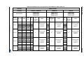
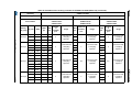
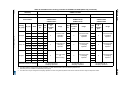
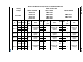
STM32L1xx available touch-sensing channels . . . . . . . . . . . . . . . . . . . 93
2.23.7
Hardware implementation example . . . . . . . . . . . . . . . . . . . . . . . . . . . 112
Getting started . . . . . . . . . . . . . . . . . . . . . . . . . . . . . . . . . . . . . . . . . . . . 114
3.1
Create your application . . . . . . . . . . . . . . . . . . . . . . . . . . . . . . . . . . . . . .114
3.1.1
Toolchain compiler preprocessor section . . . . . . . . . . . . . . . . . . . . . . . 114
DocID024201 Rev 4
5/125
6
Contents
UM1606
6/125
The tsl_conf file . . . . . . . . . . . . . . . . . . . . . . . . . . . . . . . . . . . . . . . . . . 114
3.1.3
The main file . . . . . . . . . . . . . . . . . . . . . . . . . . . . . . . . . . . . . . . . . . . . 114
3.1.4
The tsl_user file . . . . . . . . . . . . . . . . . . . . . . . . . . . . . . . . . . . . . . . . . . 114
3.2
Debug with STM Studio . . . . . . . . . . . . . . . . . . . . . . . . . . . . . . . . . . . . . .116
3.3
Low-power strategy . . . . . . . . . . . . . . . . . . . . . . . . . . . . . . . . . . . . . . . . .117
3.4
Main differences with previous library . . . . . . . . . . . . . . . . . . . . . . . . . . .118
3.5
4
3.1.2
3.4.1
Files . . . . . . . . . . . . . . . . . . . . . . . . . . . . . . . . . . . . . . . . . . . . . . . . . . . 118
3.4.2
Channels, banks and sensors configuration . . . . . . . . . . . . . . . . . . . . 118
3.4.3
Parameters configuration . . . . . . . . . . . . . . . . . . . . . . . . . . . . . . . . . . . 118
3.4.4
Usage . . . . . . . . . . . . . . . . . . . . . . . . . . . . . . . . . . . . . . . . . . . . . . . . . 119
3.4.5
Variables monitoring . . . . . . . . . . . . . . . . . . . . . . . . . . . . . . . . . . . . . . 120
Tips and tricks . . . . . . . . . . . . . . . . . . . . . . . . . . . . . . . . . . . . . . . . . . . . 123
3.5.1
Bank definition . . . . . . . . . . . . . . . . . . . . . . . . . . . . . . . . . . . . . . . . . . . 123
3.5.2
Channel assignment . . . . . . . . . . . . . . . . . . . . . . . . . . . . . . . . . . . . . . 123
3.5.3
IO Default state parameter . . . . . . . . . . . . . . . . . . . . . . . . . . . . . . . . . . 123
Revision history . . . . . . . . . . . . . . . . . . . . . . . . . . . . . . . . . . . . . . . . . . 124
DocID024201 Rev 4
UM1606
List of tables
List of tables
Table 1.
Table 2.
Table 3.
Table 4.
Table 5.
Table 6.
Table 7.
Table 8.
Table 9.
Table 10.
Table 11.
Table 12.
Table 13.
Table 14.
Table 15.
Table 16.
Table 17.
Table 18.
Table 19.
Table 20.
Table 21.
Table 22.
Table 23.
Table 24.
Table 25.
Table 26.
Table 27.
Table 28.
Table 29.
Table 30.
Table 31.
Table 32.
Table 33.
Table 34.
Table 35.
Table 36.
Table 37.
Table 38.
Table 39.
Table 40.
Table 41.
Table 42.
Terms and Acronyms . . . . . . . . . . . . . . . . . . . . . . . . . . . . . . . . . . . . . . . . . . . . . . . . . . . . . . 9
MISRA-C 2004 rules not followed. . . . . . . . . . . . . . . . . . . . . . . . . . . . . . . . . . . . . . . . . . . . 12
Supported linear and rotary sensors. . . . . . . . . . . . . . . . . . . . . . . . . . . . . . . . . . . . . . . . . . 31
Detailed sensors states 1/2 . . . . . . . . . . . . . . . . . . . . . . . . . . . . . . . . . . . . . . . . . . . . . . . . 40
Detailed sensors states 2/2 . . . . . . . . . . . . . . . . . . . . . . . . . . . . . . . . . . . . . . . . . . . . . . . . 41
STM8L101 memory footprint with software acquisition . . . . . . . . . . . . . . . . . . . . . . . . . . . 53
STM8L15x memory footprint with hardware acquisition . . . . . . . . . . . . . . . . . . . . . . . . . . . 53
STM8L15x memory footprint with software acquisition. . . . . . . . . . . . . . . . . . . . . . . . . . . . 53
MCU resources used on STM8L1xx with hardware acquisition . . . . . . . . . . . . . . . . . . . . . 54
MCU resources used on STM8L1xx with software acquisition . . . . . . . . . . . . . . . . . . . . . . 54
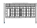
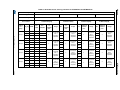
Available touch-sensing channels for STM8L101. . . . . . . . . . . . . . . . . . . . . . . . . . . . . . . . 55
Available touch-sensing channels for STM8L15x / STM8L16x (table 1/2) . . . . . . . . . . . . . 56
Available touch-sensing channels for STM8L15x / STM8L16x (table 2/2) . . . . . . . . . . . . . 58
STM8TL5x memory footprint without proximity. . . . . . . . . . . . . . . . . . . . . . . . . . . . . . . . . . 65
STM8TL5x memory footprint with proximity . . . . . . . . . . . . . . . . . . . . . . . . . . . . . . . . . . . . 65
STM8TL5x acquisition timings . . . . . . . . . . . . . . . . . . . . . . . . . . . . . . . . . . . . . . . . . . . . . . 66
STM8TL5x MCU resources used . . . . . . . . . . . . . . . . . . . . . . . . . . . . . . . . . . . . . . . . . . . . 67
Available touch-sensing channels for STM8TL5x. . . . . . . . . . . . . . . . . . . . . . . . . . . . . . . . 69
STM32F0xx memory footprint without proximity. . . . . . . . . . . . . . . . . . . . . . . . . . . . . . . . . 74
STM32F0xx memory footprint with proximity . . . . . . . . . . . . . . . . . . . . . . . . . . . . . . . . . . . 74
STM32F0xx MCU resources used . . . . . . . . . . . . . . . . . . . . . . . . . . . . . . . . . . . . . . . . . . . 74
Available touch sensing channels for STM32F042. . . . . . . . . . . . . . . . . . . . . . . . . . . . . . . 75
Available touch sensing channels for STM32F051 and STM32F072 . . . . . . . . . . . . . . . . . 77
STM32F30x memory footprint . . . . . . . . . . . . . . . . . . . . . . . . . . . . . . . . . . . . . . . . . . . . . . 82
STM32F37x memory footprint . . . . . . . . . . . . . . . . . . . . . . . . . . . . . . . . . . . . . . . . . . . . . . 82
STM32F3xx MCU resources used . . . . . . . . . . . . . . . . . . . . . . . . . . . . . . . . . . . . . . . . . . . 82
Available touch sensing channels for STM32F30x . . . . . . . . . . . . . . . . . . . . . . . . . . . . . . . 83
Available touch sensing channels for STM32F37x . . . . . . . . . . . . . . . . . . . . . . . . . . . . . . . 85
STM32L1xx_HD memory footprint without proximity . . . . . . . . . . . . . . . . . . . . . . . . . . . . . 91
STM32L1xx_HD memory footprint with proximity. . . . . . . . . . . . . . . . . . . . . . . . . . . . . . . . 91
STM32L1xx_MDP memory footprint without proximity . . . . . . . . . . . . . . . . . . . . . . . . . . . . 92
STM32L1xx_MDP memory footprint with proximity . . . . . . . . . . . . . . . . . . . . . . . . . . . . . . 92
STM32L1xx_MD memory footprint without proximity . . . . . . . . . . . . . . . . . . . . . . . . . . . . . 92
STM32L1xx_MD memory footprint with proximity . . . . . . . . . . . . . . . . . . . . . . . . . . . . . . . 92
MCU resources used on STM32L1xx with hardware acquisition . . . . . . . . . . . . . . . . . . . . 93
MCU resources used on STM32L1xx with software acquisition . . . . . . . . . . . . . . . . . . . . . 93
Available touch sensing channels for STM32L1xx 512K . . . . . . . . . . . . . . . . . . . . . . . . . . 94
Available touch sensing channels for STM32L1xx 384K . . . . . . . . . . . . . . . . . . . . . . . . . . 98
Available touch sensing channels for STM32L1xx 256K (table 1/2). . . . . . . . . . . . . . . . . 102
Available touch sensing channels for STM32L1xx 256K (table 2/2). . . . . . . . . . . . . . . . . 106
Available touch sensing channels for STM32L15x 32K to 128K . . . . . . . . . . . . . . . . . . . 109
Document revision history . . . . . . . . . . . . . . . . . . . . . . . . . . . . . . . . . . . . . . . . . . . . . . . . 124
DocID024201 Rev 4
7/125
7
List of figures
UM1606
List of figures
Figure 1.
Figure 2.
Figure 3.
Figure 4.
Figure 5.
Figure 6.
Figure 7.
Figure 8.
Figure 9.
Figure 10.
Figure 11.
Figure 12.
Figure 13.
Figure 14.
Figure 15.
Figure 16.
Figure 17.
Figure 18.
Figure 19.
Figure 20.
Figure 21.
Figure 22.
Figure 23.
Figure 24.
Figure 25.
Figure 26.
Figure 27.
Figure 28.
8/125
Installation folder 1/2. . . . . . . . . . . . . . . . . . . . . . . . . . . . . . . . . . . . . . . . . . . . . . . . . . . . . . 15
Installation folder 2/2. . . . . . . . . . . . . . . . . . . . . . . . . . . . . . . . . . . . . . . . . . . . . . . . . . . . . . 16
STMTouch driver architecture overview . . . . . . . . . . . . . . . . . . . . . . . . . . . . . . . . . . . . . . . 17
STMTouch driver detailed layers . . . . . . . . . . . . . . . . . . . . . . . . . . . . . . . . . . . . . . . . . . . . 18
Acquisition and processing layers . . . . . . . . . . . . . . . . . . . . . . . . . . . . . . . . . . . . . . . . . . . 19
Header files inclusion . . . . . . . . . . . . . . . . . . . . . . . . . . . . . . . . . . . . . . . . . . . . . . . . . . . . . 20
Channels arrangement . . . . . . . . . . . . . . . . . . . . . . . . . . . . . . . . . . . . . . . . . . . . . . . . . . . . 22
Electrodes designs . . . . . . . . . . . . . . . . . . . . . . . . . . . . . . . . . . . . . . . . . . . . . . . . . . . . . . . 30
Positions 0 and 255 . . . . . . . . . . . . . . . . . . . . . . . . . . . . . . . . . . . . . . . . . . . . . . . . . . . . . . 31
Main state machine. . . . . . . . . . . . . . . . . . . . . . . . . . . . . . . . . . . . . . . . . . . . . . . . . . . . . . . 35
Example of main state machine . . . . . . . . . . . . . . . . . . . . . . . . . . . . . . . . . . . . . . . . . . . . . 36
Simplified sensors state machine . . . . . . . . . . . . . . . . . . . . . . . . . . . . . . . . . . . . . . . . . . . . 37
DXS principle . . . . . . . . . . . . . . . . . . . . . . . . . . . . . . . . . . . . . . . . . . . . . . . . . . . . . . . . . . . 46
DXS example 1 . . . . . . . . . . . . . . . . . . . . . . . . . . . . . . . . . . . . . . . . . . . . . . . . . . . . . . . . . . 47
DXS example 2 . . . . . . . . . . . . . . . . . . . . . . . . . . . . . . . . . . . . . . . . . . . . . . . . . . . . . . . . . . 47
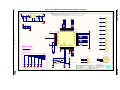
STM8L101 hardware implementation example . . . . . . . . . . . . . . . . . . . . . . . . . . . . . . . . . 63
Simplified acquisition sequencing . . . . . . . . . . . . . . . . . . . . . . . . . . . . . . . . . . . . . . . . . . . . 66
STM8TL5x hardware implementation example . . . . . . . . . . . . . . . . . . . . . . . . . . . . . . . . . 72
STM32F0xx hardware implementation example. . . . . . . . . . . . . . . . . . . . . . . . . . . . . . . . . 80
STM32F3xx hardware implementation example. . . . . . . . . . . . . . . . . . . . . . . . . . . . . . . . . 89
STM32L1xx hardware implementation example. . . . . . . . . . . . . . . . . . . . . . . . . . . . . . . . 113
STM Studio snapshot . . . . . . . . . . . . . . . . . . . . . . . . . . . . . . . . . . . . . . . . . . . . . . . . . . . . 116
Low_power strategy . . . . . . . . . . . . . . . . . . . . . . . . . . . . . . . . . . . . . . . . . . . . . . . . . . . . . 117
Debug of TSL_ChannelData_T structure . . . . . . . . . . . . . . . . . . . . . . . . . . . . . . . . . . . . . 120
Debug of TSL_TouchKeyData_T structure. . . . . . . . . . . . . . . . . . . . . . . . . . . . . . . . . . . . 121
Debug of TSL_LinRotData_T structure . . . . . . . . . . . . . . . . . . . . . . . . . . . . . . . . . . . . . . 121
Debug of TSL_TouchKeyParam_T. . . . . . . . . . . . . . . . . . . . . . . . . . . . . . . . . . . . . . . . . . 121
Debug of TSL_LinRotParam_T structures . . . . . . . . . . . . . . . . . . . . . . . . . . . . . . . . . . . . 122
DocID024201 Rev 4
UM1606
Coding rules and conventions
1
Coding rules and conventions
1.1
Glossary
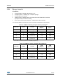
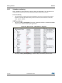
The table below summarizes all the terms and acronyms used inside this user manual.
Table 1. Terms and Acronyms
Name
Definition
Bank
A group of channels acquired simultaneously
Channel
Elementary acquisition item
Cs
Charge-Transfer sampling capacitor or
capacitance
Ct
Equivalent touch capacitance
CT
Charge-Transfer acquisition principle
Cx
Equivalent sensor capacitance
Delta
Difference between the Measure and the
Reference (for PXS acquisition)
DTO
Detection Time Out
DXS
Detection Exclusion System
ECS
Environment Change System
Linear sensor
Multi-channels sensor with the electrodes
positioned in a linear way
LinRot sensor
A linear or rotary touch sensor
Measure or Meas
Current signal measured on a channel
PXS
ProxSense acquisition peripheral used in
STM8TL5x devices
Reference or Ref
Measure of reference initialized during calibration
and then regularly updated by the ECS
Rotary
Multi-channels sensor with the electrodes
positioned in a circular way
Rs
ESD protection serial resistor
Sensor or Object
Any touch sensor (touchkey, linear, rotary,...)
Timer acquisition mode
Acquisition using two timers and PWM signals.
Also called hardware acquisition mode.
Available on STM32L1xx devices
Touchkey or TKey sensor
Single channel sensor
Zone
An ordered set of banks
DocID024201 Rev 4
9/125
124
Coding rules and conventions
1.2
UM1606
Naming conventions
The following naming conventions are used in the STMTouch driver source files:
1.3
•
Source and header files are in lower-case and preceded by 'tsl' or 'tsl_'.
•
The microcontroller family is added at the end of the file name if needed.
•
Functions, globals, typedefs and defines are preceded by 'TSL'.
•
Constants are written in upper case and preceded by 'TSLPRM_'.
•
Constants used in one file are defined within this file only.
•
Constants used in more than one file are defined in a header file.
•
Typedef names are suffixed with '_T'.
•
Enum typedefs are suffixed with '_enum_T'.
•
Functions are preceded 'TSL_[module]_[function]'.
–
[module]: abbreviation of the file (acq, tim, dxs, etc...)
–
[function]: the first letter in each word is in upper case
Coding rules
This section describes the coding rules used in the STMTouch driver source files.
1.3.1
1.3.2
General
•
Source code complies with ANSI C standard.
•
No warning after compilation. Any warnings that cannot be eliminated are commented
in the source code.
•
ANSI standard data types are used and defined in the ANSI C header file <stdint.h>.
•
No blocking code is present and all required waiting loops (polling loops) are controlled
by a timeout.
Variable types
Specific variable types are already defined with a fixed type and size.
1.3.3
•
The types that are used by all modules are defined in the tsl_types.h file.
•
Other variable types are defined in their corresponding module header file.
Peripheral registers
The peripheral registers are accessed using the pointers described in the standard
peripherals library mapping file.
1.4
Run-time checking
The STMTouch driver implements run-time failure detection by checking the functions input
parameters. The run-time checking is achieved using the assert_param macro defined in
the standard peripherals library configuration file. It is enabled when the preprocessor
constant USE_FULL_ASSERT is defined.
10/125
DocID024201 Rev 4
UM1606
Coding rules and conventions
Because of the overhead it introduces, it is recommended to use run-time checking during
application code development and debugging, and to remove it from the final application to
improve code size and speed.
However if you want to keep this functionality in your final application, reuse the
assert_param macro defined in the standard peripherals library to test the parameter values
before calling the STMTouch driver functions.
Please see the standard peripherals library user manual for more informations.
1.5
MISRA-C 2004 compliance
1.5.1
Generalities
The C programming language is growing in importance for embedded systems. However,
when it comes to developing code for safety-critical applications, this language has many
drawbacks. There are several unspecified, implementation-defined, and undefined aspects
of the C language that make it unsuited for developing safety-critical systems.
The motor industry software reliability association's guidelines for the use of the C language
in critical systems (MISRA-C 2004 [1]) describe a subset of the C language well suited for
developing safety-critical systems.
The STMTouch driver has been developed to be MISRA-C 2004 compliant.
The following section describes how the STMTouch driver complies with MISRA-C 2004 (as
described in section 4.4 Claiming compliance of the standard [1]):
1.5.2
•
A compliance matrix has been completed which shows how compliance has been
enforced.
•
The whole STMTouch driver source code is compliant with MISRA-C 2004 rules.
•
Deviations are documented. A list of all instances of rules not being followed is being
maintained, and for each instance there is an appropriately signed-off deviation.
•
All the issues listed in section 4.2 “The programming language and coding context of
the standard” [1], that need to be checked during the firmware development phase,
have been addressed during the development of the STMTouch driver and appropriate
measures have been taken.
Compliance matrix
The compliance of the STMTouch driver with MISRA-C 2004 has been checked in two
ways:
•
using PC-lint tool for C/C++ (NT) vers. 8.00v, copyright gimpel software 1985-2006
•
performing regular code reviews.
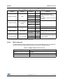
The following table lists the MISRA-C 2004 rules that are frequently violated in the code:
DocID024201 Rev 4
11/125
124
Coding rules and conventions
UM1606
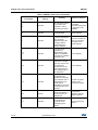
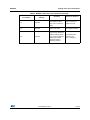
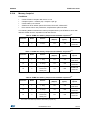
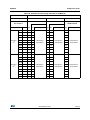
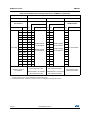
Table 2. MISRA-C 2004 rules not followed
MISRA-C 2004
Required/
rule number
advisory
Reason of deviance
Compilers extensions
are enabled.
Comments starting with
“//” symbol for code
readability.
1.1
1.2
Required
All code shall conform
to ISO 9899:1990
standard C, with no
extensions permitted.
5.4
Required
A tag name shall be a
unique identifier.
Due to the usage of
objects methods.
Required
No prototype seen.
Functions shall always
have prototype
declarations and the
prototype shall be
visible at both the
function definition.
This rule is violated as
there is no functions
prototypes for the
objects methods.
Required
The value of an
expression of
integer/floating type
shall not be implicitly
converted to a different
underlying type.
Code complexity
Required
The value of a complex
expression of integer
type may only be cast
to a type that is
Code complexity
narrower and of the
same signedness as
the underlying type of
the expression.
Required
If the bitwise operators
are applied to an
operand of underlying
type unsigned char or
unsigned short, the
result shall be
immediately cast to the
underlying type of the
operand.
Use shift on signed
quantity for the
linear/rotary position
Advisory
A cast should not be
performed between a
pointer type and an
integral type.
Needed when
addressing memory
mapped registers.
Required
Bitwise operators shall
not be applied to
operands whose
underlying type is
signed.
Shift of signed value
needed
8.1
10.1
10.2
10.3
10.5
11.3
12.7
12/125
Summary
DocID024201 Rev 4
UM1606
Coding rules and conventions
Table 2. MISRA-C 2004 rules not followed (continued)
MISRA-C 2004
Required/
rule number
advisory
Summary
Reason of deviance
14.3
Required
Before preprocessing, a
null statement shall
Usage of macros to
only occur on a line by simplify the code
itself.
14.5
Required
The continue statement Used to optimize the
shall not be used.
code speed execution.
Required
All macro identifiers in
preprocessor directives
shall be defined before All parameters are
use, except in ifdef and checked in the
ifndef preprocessor
check_config files
directives and the
defined() operator.
19.11
DocID024201 Rev 4
13/125
124
STMTouch driver
UM1606
2
STMTouch driver
2.1
Supported devices and development tools
2.1.1
Supported devices
This STMTouch driver version supports the following devices and acquisition modes:
•
•
•
•
14/125
Support of STM8L1xx devices
–
Surface charge-transfer acquisition principle managed by:
–
Two timers + routing interface (hardware acquisition mode, supported only by
STM8L15x low-density devices)
–
GPIOs + routing interface (software acquisition mode, supported by all STM8L
devices)
–
Up to 6 channels with up to 2 channels acquired simultaneously for the STM8L101
devices (see Table 11 for more details)
–
Up to 20 channels with up to 8 channels acquired simultaneously for the
STM8L15x/16x devices (see Table 12 and Table 13 for more details)
STM8TL5x devices using the embedded ProxSense™ patented acquisition
technology.
–
Projected ProxSense™ acquisition principle
–
Up to 300 channels
–
Up to 10 channels can be acquired simultaneously (see Table 18 for more details)
–
Integrated sampling capacitor
–
Electrode parasitic capacitance compensation (EPCC)
–
On-chip integrated voltage regulator
Support of STM32L1xx devices
–
Surface charge-transfer acquisition principle managed by:
–
Two timers + routing interface (hardware acquisition mode). This mode is not
supported on Medium-density devices.
–
GPIOs + routing interface (software acquisition mode). This mode is supported by
all devices.
–
Up to 34 channels
–
Up to 11 channels can be acquired simultaneously (see Table 37, Table 38,
Table 39, Table 40 and Table 41 for more details)
STM32F0xx and STM32F3xx devices using the embedded touch sensing controller IP
(TSC).
–
Surface charge-transfer acquisition principle managed by the touch sensing
controller
–
Up to 24 channels
–
Up to 8 channels can be acquired simultaneously (see Table 22, Table 23,
Table 27 and Table 28 for more details)
–
Spread spectrum feature
–
Programmable charge transfer frequency and max count value
DocID024201 Rev 4
UM1606
2.1.2
STMTouch driver
Development tools
The STM8 and STM32 microcontrollers are supported by a full range of development
solutions from lead suppliers that deliver start-to-finish control of application development
from a single integrated development environment.
The STMTouch driver has been developed with the following toolchains and compilers:
•
STVD (STMicroelectronics) + Raisonance and Cosmic compilers
•
EWSTM8 and EWARM (IAR)
•
MDK-ARM (Keil)
•
Tasking (Altium®)
•
TrueSTUDIO®-C (Atollic®)
•
Ride7 / RKit-Arm (Raisonance)
For more details about the compilers versions used, please see the STMTouch driver
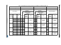
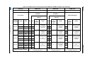
release note (present in the STMTouch Library installation folder).
2.2
Package description
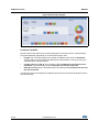
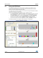
The STMTouch driver is not supplied by itself. It is delivered instead inside each device
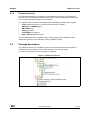
STMTouch library (STMTouch_Driver folder present in the Libraries folder).
The following snapshots show an example of installation.
Figure 1. Installation folder 1/2
DocID024201 Rev 4
15/125
124
STMTouch driver
UM1606
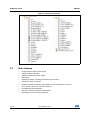
Figure 2. Installation folder 2/2
2.3
16/125
Main features
•
Environment Change System (ECS)
•
Detection Time Out (DTO)
•
Detection Exclusion System (DXS)
•
Noise filter
•
Supports proximity, touchkeys and linear touch sensors
•
Unlimited number of sensors
•
Modular architecture allowing easy addition of new acquisitions or sensors
•
Each sensor can have its own state machine
•
Simplified timing management
•
Run-time checking of functions parameters
•
Management of error during acquisition
DocID024201 Rev 4
UM1606
STMTouch driver
2.4
Architecture
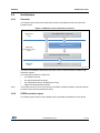
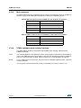
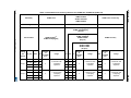
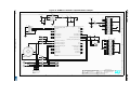
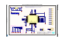
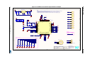
2.4.1
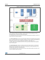
Overview
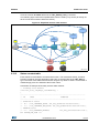
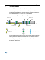
The following figure shows the interactions between the STMTouch driver and the other
firmware layers.
Figure 3. STMTouch driver architecture overview
$SSOLFDWLRQ
OD\HU
8VHUDSSOLFDWLRQVH[DPSOHV
6707RXFKGULYHU
+DUGZDUH
DEVWUDFWLRQOD\HU
+$/
6WDQGDUGSHULSKHUDOVOLEUDU\
+DUGZDUH
OD\HU
0&8
06Y9
The HAL is the hardware abstraction layer (HAL) which controls the device itself through
hardware registers.
It is composed of different components:
•
The STMTouch driver
•
The standard peripherals library
•
The CMSIS firmware (for STM32 devices only)
•
Utilities and third-parties firmwares
Note:
The STMTouch driver can access directly to the MCU hardware registers using the map file
provided by the standard peripherals library.
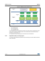
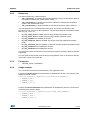
2.4.2
STMTouch driver layers
The following figure shows a more detailed view of the different STMTouch driver layers.
DocID024201 Rev 4
17/125
124
STMTouch driver
UM1606
Figure 4. STMTouch driver detailed layers
$SSOLFDWLRQ
OD\HU
6707RXFKGULYHU
FRQILJXUDWLRQ
8VHUDSSOLFDWLRQ
3URFHVVLQJ
OD\HU
6707RXFK
GULYHU
'72
';6
7LPLQJ
(&6
)LOWHUV
7RXFKNH\
VHQVRU
/LQHDUDQG
URWDU\VHQVRUV
$FTXLVLWLRQ
0&8
$FTXLVLWLRQ $F
$FTXLVLWLRQ
FT$FTXLVLWLRQ
XLVLWLRQ
OD\HU
0&8
0&8
0
0&8
6WDQGDUGSHULSKHUDOV
OLEUDU\
06Y9
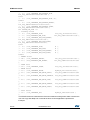
The STMTouch driver is composed of three main layers:
•
The acquisition layer
•
The processing layer
•
The configuration layer
The configuration layer corresponds to what the user needs to write in its application code in
order to use correctly the STMTouch driver. This includes all the channels and sensors
declaration, the parameters, etc...
The acquisition and processing layers are described more in detail below.
2.4.3
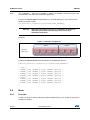
Acquisition and processing layers
The following figure details the acquisition and processing layers and the different elements
used in each layer.
18/125
DocID024201 Rev 4
UM1606
STMTouch driver
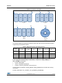
Figure 5. Acquisition and processing layers
$FTXLVLWLRQ
OD\HU
FKDQQHO
EDQN
]RQH
&KDQQHO
GDWDOD\HU
VHQVRUV
3URFHVVLQJ
OD\HU
WRXFKNH\
OLQHDUURWDU\
(&6
';6
'72
)LOWHUV
7LPLQJ
06Y9
The acquisition layer role is to perform the acquisition of the different channels. The result
of the acquisition (measure and flags) is stored inside the channel data layer. These
informations will be accessed by the processing layer.
The acquisition layer has only access to the channel, bank and zone elements. It does not
have access to the sensor elements.
The channel data layer role is to share information between the acquisition and processing
layers. It stores the result of the acquisition (measure) for each channel and store different
informations coming from the processing layer (reference, delta, flags, etc...).
Located in RAM, the ChannelData structure is the only interface between the acquisition
and processing layers.
This processing layer consists in executing each sensors state machine, executing the
different data processing like ECS, DXS, DTO and storing any useful information for the
acquisition layer inside the channel data area.
The processing layer does not have direct access to the channels, banks and zones. This
access is made through the sensors.
DocID024201 Rev 4
19/125
124
STMTouch driver
2.4.4
UM1606
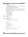
Header files inclusion
The figure below provides a global view of the STMTouch driver usage and the interaction
between the different header files.
Note:
To simplify the drawing, only the most important links are shown. For example the
tsl_globals.h file is also included in different files.
Figure 6. Header files inclusion
$SSOLFDWLRQ
OD\HU
PDLQK
WVOBFRQIBPFX!K
WVOBILOWHUK
WVOBHFVK
WVOBFKHFNBFRQILJK
WVOBG[VK
WVOBFKHFNBFRQILJBPFX!K
WVOBREMHFWK
6707RXFK
GULYHU
WVOK
WVOBWRXFKNH\K
WVOBOLQURWK
WVOBDFTBPFX!K
WVOBDFTK
WVOBW\SHVK
WVOBWLPHK
WVOBWLPHBPFX!K
WVOBJOREDOVK
6WDQGDUG
SHULSKHUDO
OLEUDU\
PFX!KPDSSLQJILOH
06Y9
2.5
Channel
2.5.1
Principle
A channel is the basic element that is used to store several information like:
20/125
•
where the source measurement can be found after the acquisition is performed (i.e. RX
registers for STM8TL5x devices or TSC_IOGxCR registers for
STM32F0xx/STM32F3xx devices)
•
where are stored the measure, the reference, the delta, flags etc...
DocID024201 Rev 4
UM1606
2.5.2
STMTouch driver
Resources
A channel is defined by 3 data structures:
•
TSL_ChannelSrc_T: contains all information about the source measurement (index of
the register containing the measurement, masks,...)
•
TSL_ChannelDest_T: contains all information about the measurement destination
(index in the channel data array).
•
TSL_ChannelData_T: contains all data for the channel (measure, delta, reference, ...)
The channel depends on the acquisition technology. This is why the contents of this
structures are not common for all acquisitions. They are declared in each acquisition header
files (tsl_acq_<mcu>.h):
•
tsl_acq_stm8l_hw.h for STM8L devices using hardware acquisition mode
•
tsl_acq_stm8l_sw.h for STM8L devices using software acquisition mode
•
tsl_acq_stm8tl5x.h for STM8TL5x devices
•
tsl_acq_stm32l1xx_hw.h for STM32L1xx devices using the hardware acquisition
mode
•
tsl_acq_stm32l1xx_sw.h for STM32L1xx devices using the software acquisition mode
•
tsl_acq_stm32f0xx.h for STM32F0xx devices
•
tsl_acq_stm32f3xx.h for STM32F3xx devices
The maximum number of channels is only limited by the device (memory size and channels
supported).
The user must declare all the channels array in its application code. It can be done directly
in the main.c file or in any other file.
2.5.3
Parameters
•
2.5.4
TSLPRM_TOTAL_CHANNELS
Usage example
The 3 channels structures must be declared in the application code.
Example of channel source array declaration for STM32F0xx devices. This structure must
always be placed in ROM.
const TSL_ChannelSrc_T MyChannels_Src[TSLPRM_TOTAL_CHANNELS] =
{ { CHANNEL_0_SRC },
{ CHANNEL_1_SRC },
{ CHANNEL_2_SRC }};
Example of channel destination array declaration for STM32F0xx devices. This structure
must always be placed in ROM.
const TSL_ChannelDest_T MyChannels_Dest[TSLPRM_TOTAL_CHANNELS] =
{ { CHANNEL_0_DEST },
{ CHANNEL_1_DEST },
{ CHANNEL_2_DEST }};
DocID024201 Rev 4
21/125
124
STMTouch driver
Note:
UM1606
The "CHANNEL_x_SRC" and "CHANNEL_x_DEST" are "#define" constants and are used
for readability. The values are acquisition dependant.
Example of channel data array declaration (i.e. channel data layer). This structure must
always be placed in RAM.
TSL_ChannelData_T MyChannels_Data[TSLPRM_TOTAL_CHANNELS];
Warning:
When several banks are present, it is mandatory to declare all
channels of each bank consecutively in the source and
destination structures.
Example:
Figure 7. Channels arrangement
%DQN
&KDQQHO
GDWDOD\HU
&+
&+
&+
%DQN
&+
&+
&+
&+
06Y9
Example of channel source array declaration for STM32F0xx devices.
CONST TSL_ChannelSrc_T MyChannels_Src[TSLPRM_TOTAL_CHANNELS] =
{
// Bank 1
{ CHANNEL_0_SRC, CHANNEL_0_IO_MSK, CHANNEL_0_GRP_MSK },
{ CHANNEL_1_SRC, CHANNEL_1_IO_MSK, CHANNEL_1_GRP_MSK },
{ CHANNEL_2_SRC, CHANNEL_2_IO_MSK, CHANNEL_2_GRP_MSK },
{ CHANNEL_3_SRC, CHANNEL_3_IO_MSK, CHANNEL_3_GRP_MSK },
// Bank 2
{ CHANNEL_4_SRC, CHANNEL_4_IO_MSK, CHANNEL_4_GRP_MSK },
{ CHANNEL_5_SRC, CHANNEL_5_IO_MSK, CHANNEL_5_GRP_MSK },
{ CHANNEL_6_SRC, CHANNEL_6_IO_MSK, CHANNEL_6_GRP_MSK }
};
2.6
Bank
2.6.1
Principle
A bank is a group of channels that are acquired simultaneously. The number of channels in
the bank is variable.
22/125
DocID024201 Rev 4
UM1606
2.6.2
STMTouch driver
Resources
The bank data are held by only one structure:
•
TSL_Bank_T
•
The bank depends also on the acquisition technology. These structures are declared in
each acquisition header files (tsl_acq_<mcu>.h):
The maximum number of banks is only limited by the device.
The user must declare all the banks array in its application code. It can be done directly in
the main.c file or in any other file.
The banks are used mainly by the functions described below. Some functions are common
whatever the device and acquisition technology. Some others are dependent on the device.
Common functions:
•
TSL_acq_BankGetResult()
•
TSL_acq_BankCalibrate()
Device dependent functions:
2.6.3
•
TSL_acq_BankConfig()
•
TSL_acq_BankStartAcq()
•
TSL_acq_BankWaitEOC()
Parameters
•
2.6.4
TSLPRM_TOTAL_BANKS
Usage example
Example of 2 banks declaration for STM8TL5x devices:
// Always placed in ROM
const TSL_Bank_T MyBanks[TSLPRM_TOTAL_BANKS] =
{
// Bank 0
&MyChannels_Src[0],
&MyChannels_Dest[0],
MyChannels_Data,
BANK_0_NBCHANNELS,
// For STM8TL5x acquisition only
BANK_0_MSK_CHANNELS,
BIT_MASK_TX(BANK_0_TX),
BANK_0_GROUP,
#if (BANK_0_MSK_TX < 0x8000) // a TX pin is used as transmitter
BANK_0_MSK_CHANNELS,
#else // a RX pin is used as transmitter
(BIT_MASK_RX(BANK_0_TX)| BANK_0_MSK_CHANNELS),
#endif
// Bank 1
DocID024201 Rev 4
23/125
124
STMTouch driver
UM1606
&MyChannels_Src[4],
&MyChannels_Dest[4],
MyChannels_Data,
BANK_1_NBCHANNELS,
// For STM8TL5x acquisition only
BANK_1_MSK_CHANNELS,
BIT_MASK_TX(BANK_1_TX),
BANK_1_GROUP,
#if (BANK_1_MSK_TX < 0x8000) // a TX pin is used as transmitter
BANK_1_MSK_CHANNELS,
#else // a RX pin is used as transmitter
(BIT_MASK_RX(BANK_1_TX)| BANK_1_MSK_CHANNELS),
#endif
};
The "BANK_x_NBCHANNELS", "BANK_x_MSK_CHANNELS", "BIT_x_MASK_TX", etc...
are defines and are used for readability. These values are for STM8TL5x devices acquisition
only.
Example of 3 banks declaration for STM32F0xx devices:
CONST TSL_Bank_T MyBanks[TSLPRM_TOTAL_BANKS] = {
{&MyChannels_Src[0], &MyChannels_Dest[0], MyChannels_Data,
BANK_0_NBCHANNELS, BANK_0_MSK_CHANNELS, BANK_0_MSK_GROUPS},
{&MyChannels_Src[1], &MyChannels_Dest[1], MyChannels_Data,
BANK_1_NBCHANNELS, BANK_1_MSK_CHANNELS, BANK_1_MSK_GROUPS},
{&MyChannels_Src[2], &MyChannels_Dest[2], MyChannels_Data,
BANK_2_NBCHANNELS, BANK_2_MSK_CHANNELS, BANK_2_MSK_GROUPS}
};
2.7
Zone
2.7.1
Principle
A zone is an ordered group of banks. It is used to easily cascade the acquisition of many
banks. The acquisition of the next bank in a zone is launched directly in the interrupt routine
managing the acquisition result of the current acquired bank.
2.7.2
Resources
This feature is optional and is enabled/disabled using the TSLPRM_USE_ZONE parameter.
The zone data are held by only one structure:
•
TSL_Zone_T
The zones are used mainly by the function:
•
24/125
TSL_acq_ZoneConfig()
DocID024201 Rev 4
UM1606
2.7.3
STMTouch driver
Parameters
•
2.7.4
TSLPRM_USE_ZONE
Usage example
Example of a zone declaration containing 3 banks:
TSL_tIndex_T MyBankSorting[TSLPRM_TOTAL_BANKS] = {2, 0, 1, 3, 4, 5};
TSL_Zone_T MyZone = {
MyBankSorting,
0,
3 // Number of Banks in the Zone
};
In this example the "MyBankSorting" array contains the list of the banks indexes to acquire.
And only the 3 first Banks will be acquired (indexes 2, 0 and 1).
2.8
Objects
2.8.1
Principle
The term “object” or “sensor” stands for any sensors type (touchkeys, linear and rotary
touch sensors, etc...) supported by the STMTouch driver.
2.8.2
Resources
All processing that affect the sensors in general are defined in:
•
tsl_object.c
•
tsl_object.h
The functions are:
•
TSL_obj_GroupInit()
•
TSL_obj_GroupProcess()
•
TSL_obj_SetGlobalObj()
A sensor is described by the structures:
2.8.3
•
TSL_Object_T
•
TSL_ObjectGroup_T
Parameters
•
2.8.4
TSLPRM_TOTAL_OBJECTS
Usage example
First, all touchkeys, linear and rotary touch sensors (described after) used in the application
must be described first as 'generic' sensor or object.
Example:
// Mix of touchkeys and Linear touch sensors
DocID024201 Rev 4
25/125
124
STMTouch driver
UM1606
const TSL_Object_T MyObjects[TSLPRM_TOTAL_OBJECTS] =
{
// TKeys
{ TSL_OBJ_TOUCHKEYB, (TSL_TouchKeyB_T *)&MyTKeys[0]
},
{ TSL_OBJ_TOUCHKEYB, (TSL_TouchKeyB_T *)&MyTKeys[1]
},
// Linear touch sensors
{ TSL_OBJ_LINEARB,
(TSL_LinRotB_T
*)&MyLinRots[0] }
};
These objects must be placed in ROM memory.
Once this done, it is necessary to create at least one group of sensors. These groups will be
used by the different processing routines (ECS, DXS, etc...).
These groups of objects must placed in RAM.
Example:
TSL_ObjectGroup_T MyObjGroup_All = {
MyObjects,
3,
0,
TSL_STATE_NOT_CHANGED
};
Then, all the sensors must be initialized and “processed”. This is done in the main function
of the application:
int main(void) {
...
TSL_obj_GroupInit(&MyObjGroup_All);
...
while (1) {
...
TSL_obj_GroupProcess(&MyObjGroup_All);
...
}
}
2.9
Touchkey sensor
2.9.1
Principle
The touchkey sensor is composed of only one channel. It acts as a simple “button” with two
states RELEASE and DETECT (or TOUCH if DXS is enabled).
2.9.2
Resources
All the functions related to this sensor are described in the files:
26/125
•
tsl_touchkey.c
•
tsl_touchkey.h
DocID024201 Rev 4
UM1606
STMTouch driver
Two types of touchkey sensor are available:
•
Basic: defined by the TSL_TouchKeyB_T structure
•
Extended: defined by the TSL_TouchKey_T structure
Two functions (called methods) are used to initialized the sensor parameters and to run the
sensor state machine:
•
TSL_tkey_Init()
•
TSL_tkey_Process()
The difference between the “basic” and “extended” concerns the usage of the methods and
sensor state machine.
For the “basic” sensor, the methods and state machine are those used in the TSL_Params
structure.
For the “extended” sensor, the methods and state machine are those declared in their own
structure.
2.9.3
Parameters
•
2.9.4
TSLPRM_TOTAL_TKEYS
Usage example
The user must declared these methods in the application code.
Note:
One can also use its own initialization and process functions instead:
const TSL_TouchKeyMethods_T MyTKeys_Methods =
{
TSL_tkey_Init,
TSL_tkey_Process
};
The declaration of the touchkey sensor is done by the user in the application code:
Example with “basic” sensor:
// "Basic" touchkeys: Always placed in ROM
const TSL_TouchKeyB_T MyTKeys[TSLPRM_TOTAL_TKEYS] =
{
{ &MyTKeys_Data[0], &MyTKeys_Param[0], &MyChannels_Data[0] },
{ &MyTKeys_Data[1], &MyTKeys_Param[1], &MyChannels_Data[1] },
{ &MyTKeys_Data[2], &MyTKeys_Param[2], &MyChannels_Data[2] }
};
Example with “extended” sensor:
// "Extended" TouchKeys: Always placed in ROM
const TSL_TouchKey_T MyTKeys[TSLPRM_TOTAL_TKEYS] =
{
{ &MyTKeys_Data[0], &MyTKeys_Param[0], &MyChannels_Data[0],
MyTKeys_StateMachine, &MyTKeys_Methods },
{ &MyTKeys_Data[1], &MyTKeys_Param[1], &MyChannels_Data[1],
MyTKeys_StateMachine, &MyTKeys_Methods },
DocID024201 Rev 4
27/125
124
STMTouch driver
UM1606
{ &MyTKeys_Data[2], &MyTKeys_Param[2], &MyChannels_Data[2],
MyTKeys_StateMachine, &MyTKeys_Methods }
};
2.10
Linear and rotary sensors
2.10.1
Principle
The linear and rotary sensors are like a touchkey sensor except that they are composed of a
variable number of channels. The difference between the linear and rotary touch sensors is
how the electrodes are organized together.
The linear and rotary sensors have additional fields in their structure compared to touchkey
sensors:
•
Number of channels
•
Delta coefficient table
•
Position offset table
•
Sector computation parameter
•
Position correction parameter for linear sensor
The last 3 fields are used to calculate the position.
2.10.2
Number of channels
Only 1, 3, 4, 5 and 6 channels are supported today by the STMTouch driver. Additional
number of channels can be added by the end-user. See the Position offset table bullet
below for more detail.
Note:
A Linear sensor with 1 channel is equivalent to one touchkey sensor. When an application
uses both touchkey sensor and linear and rotary sensor, it is better to use touchkeys with a
1-channel linear touch sensor. In this case the gain in memory size is important as the
touchkey sensor state machine is not used.
2.10.3
Delta coefficient table
The delta coefficient table is used to adjust each channel of the linear and rotary sensors.
Each value is a 16-bit integer. The MSB is the integer part, the LSB is the real part.
Examples:
To apply a factor of 1.10:
•
MSB equal 0x01
•
LSB equal 0x1A (0.10 x 256 = 25.6 -> rounded to 26 = 0x1A)
To apply a factor 1.00:
•
MSB equal 0x01
•
LSB equal 0x00
To apply a factor 0.90:
28/125
•
MSB equal 0x00
•
LSB equal 0xE6 (0.90 x 256 = 230.4 -> rounded to 230 = 0xE6)
DocID024201 Rev 4
UM1606
STMTouch driver
This results in the following delta coefficient table:
CONST uint16_t MyLinRot0_DeltaCoeff[3] = {0x011A, 0x0100, 0x00E6};
The number of delta coefficient table is not limited. The same delta coefficient table can be
shared by several linear and rotary sensors.
2.10.4
Electrodes placement
The placement (design) of the electrodes can be done in three different manners:
1.
Mono electrode design
The number of electrodes is equivalent to the number of channels. This design is used
for linear and rotary sensors.
Abbreviations: LIN_M1, LIN_M2 and ROT_M
Examples:
–
2.
CH1 CH2 CH3
–
CH1 CH2 CH3 CH4
–
CH1 CH2 CH3 CH4 CH5
Dual electrode design
All the electrodes are duplicated and interlaced together in order to increase the touch
area.
This design is used for linear and rotary sensors composed with at least 5 channels.
Abbreviation: LIN_D and ROT_D
Examples with 5 channels:
3.
–
CH1 CH2 CH3 CH4 CH5 CH1 CH3 CH5 CH2 CH4
–
CH1 CH2 CH3 CH4 CH5 CH2 CH4 CH1 CH3 CH5
–
CH1 CH2 CH3 CH4 CH5 CH3 CH1 CH4 CH2 CH5
Half-ended electrode design
The first electrode is duplicated and the replica is placed at the end. The size of the first
and last electrode is half the size of the other electrodes. This design is used for linear
sensors only. The 0 and 255 positions are obtained more easily compared to the
Mono electrodes design.
Abbreviation: LIN_H
Examples:
–
ch1 CH2 CH3 ch1
–
ch1 CH2 CH3 CH4 ch1
–
ch1 CH2 CH3 CH4 CH5 ch1
The following figure summarizes the different electrodes designs we can have on linear and
rotary sensors:
DocID024201 Rev 4
29/125
124
STMTouch driver
UM1606
Figure 8. Electrodes designs
/LQHDU
0RQR
HOHFWURGHV
GHVLJQ
/,1B0
/,1B0
+DOIHQGHG
HOHFWURGHV
GHVLJQ
/,1B+
5RWDU\
527B0
&+ &+ &+
FK &+ &+ FK
527B'
/,1B'
'XDO
HOHFWURGHV
GHVLJQ
&+ &+ &+ &+ &+ &+ &+ &+ &+ &+
06Y9
Positions 0 and 255
Special care must be taken for the 0 and 255 positions on linear sensors. These positions
are placed differently depending on the electrodes design used:
•
LIN_M1: the 0 and 255 positions are placed completely at the sensor's extremities.
These positions can be obtain with difficulty if the electrodes are too big or if they are
separated by an important space.
•
LIN_M2, LIN_H and LIN_D: the 0 position is placed between the first and second
electrodes. The 255 position is placed between the last two electrodes.
•
ROT_M and ROT_D: the 0 and 255 positions are always placed between the first and
the last electrodes.
The following figures summarizes the different placements of the 0 and 255 positions with 4
channels sensors:
30/125
DocID024201 Rev 4
UM1606
STMTouch driver
Figure 9. Positions 0 and 255
&+
&+
&+
&+
&+
&+
&+
/,1B0
/,1B0
FK
&+
&+
&+
&+
&+
&+
&+
&+
FK
/,1B+
527B0
/,1B'
527B'
06Y9
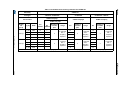
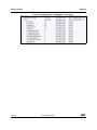
The following table summarizes the different linear and rotary sensors electrodes designs
supported by the STMTouch driver:
Table 3. Supported linear and rotary sensors
Number
of Channels
LIN_M1
LIN_M2
LIN_H
LIN_D
ROT_M
ROT_D
3
Yes
Yes
Yes
No
Yes
No
4
Yes
Yes
Yes
No
Yes
No
5
Yes
Yes
Yes
No
Yes
Yes
6
Yes
Yes
Yes
No
Yes
No
Each supported electrode design is described by 3 fields in the TSL_LinRot_T or
TSL_LinRotB_T structures:
•
Position offset table
•
Sector computation parameter
•
Position correction parameter for linear sensor
These 3 fields are defined in the tsl_linrot.c and tsl_linrot.h files and follow the naming
convention:
Position offset table: TSL_POSOFF_nCH_[LIN|ROT]_[M1|M2|H|D]
DocID024201 Rev 4
31/125
124
STMTouch driver
UM1606
Sector computation parameter: TSL_SCTCOMP_nCH_[LIN|ROT]_[M1|M2|H|D]
Position correction parameter for linear sensor: TSL_POSCORR_nCH_LIN_[M1|M2|H|D]
With:
•
n = number of channels
•
LIN = linear sensor
•
ROT = rotary sensor
•
M1 = mono electrodes design with 0/255 position at extremities
•
M2 = mono electrodes design
•
H = half-ended electrodes design
•
D = dual electrodes design
In order to gain memory space, each table is only compiled if its corresponding parameter is
set in the configuration file:
TSLPRM_USE_nCH_[LIN|ROT]_[M1|M2|H|D]
2.10.5
Resources
All the functions related to this sensor are described in the files:
•
tsl_linrot.c
•
tsl_linrot.h
Two types of linear and rotary sensor are available:
•
basic: defined by the TSL_LinRotB_T structure
•
extended: defined by the TSL_LinRot_T structure
The difference between “basic” and “extended” is the same as for the touchkey sensor.
Three functions (called methods) are used to initialized the sensor parameters, run the
sensor state machine and calculate the position.
2.10.6
•
TSL_linrot_Init()
•
TSL_linrot_Process()
•
TSL_linrot_CalcPos()
Parameters
•
2.10.7
TSLPRM_TOTAL_LINROTS
Usage example
The user must declared these methods in the application code.
Note:
One can also use its own initialization and process functions instead:
CONST TSL_LinRotMethods_T MyLinRots_Methods =
{
TSL_linrot_Init,
TSL_linrot_Process,
TSL_linrot_CalcPos
};
32/125
DocID024201 Rev 4
UM1606
STMTouch driver
The declaration of the linear and rotary sensor is done by the user in the application code in
the same manner as for touchkey sensor.
Example with 2 “basic” linear touch sensors, one with 3 channels half-ended and the other
with 5 channels mono electrodes design:
CONST TSL_LinRotB_T MyLinRots[2] =
{
// LinRot sensor 0
&MyLinRots_Data[0],
&MyLinRots_Param[0],
&MyChannels_Data[CHANNEL_9_DEST],
3, // Number of channels
MyLinRot0_DeltaCoeff, // Delta coefficient table
(TSL_tsignPosition_T *)TSL_POSOFF_3CH_LIN_H, // Position table
TSL_SCTCOMP_3CH_LIN_H, // Sector compensation
TSL_POSCORR_3CH_LIN_H, // Position correction
// LinRot sensor 1
&MyLinRots_Data[1],
&MyLinRots_Param[1],
&MyChannels_Data[CHANNEL_12_DEST],
5, // Number of channels
MyLinRot1_DeltaCoeff, // Delta coefficient table
(TSL_tsignPosition_T *)TSL_POSOFF_5CH_LIN_M2, // Position table
TSL_SCTCOMP_5CH_LIN_M2, // Sector compensation
TSL_POSCORR_5CH_LIN_M2
// Position correction
};
Example of one “extended” (i.e. having its own state machine and methods) linear touch
sensor with 3 channels half-ended:
CONST TSL_LinRot_T MyLinRots[1] =
{
// LinRot sensor 0
&MyLinRots_Data[0],
&MyLinRots_Param[0],
&MyChannels_Data[CHANNEL_0_DEST],
3, // Number of channels
MyLinRot0_DeltaCoeff,
(TSL_tsignPosition_T *)TSL_POSOFF_3CH_LIN_H,
TSL_SCTCOMP_3CH_LIN_H,
TSL_POSCORR_3CH_LIN_H,
MyLinRots_StateMachine, // Specific state machine
&MyLinRots_Methods // Specific methods
};
Example of one “extended” rotary touch sensor with 3 channels mono electrode design:
CONST TSL_LinRot_T MyLinRots[0] =
{
DocID024201 Rev 4
33/125
124
STMTouch driver
UM1606
// LinRot sensor 0
&MyLinRots_Data[0],
&MyLinRots_Param[0],
&MyChannels_Data[CHANNEL_0_DEST],
3, // Number of channels
MyLinRot0_DeltaCoeff,
(TSL_tsignPosition_T *)TSL_POSOFF_3CH_ROT_M,
TSL_SCTCOMP_3CH_ROT_M,
0, // No position correction needed on a Rotary sensor
MyLinRots_StateMachine, // Specific state machine
&MyLinRots_Methods // Specific methods
};
2.11
Main state machine
The main state machine is managed by the user in the application layer. A set of functions
are available to accomplish this task. The main state machine can be defined with polling or
with interrupt modes, using one or several banks. The modularity of the STMTouch driver
allows also the application code to be inserted between acquisition and processing tasks.
Several examples are given below.
The functions to use for the acquisition are:
•
TSL_acq_BankConfig()
•
TSL_acq_BankStartAcq()
•
TSL_acq_BankWaitEOC()
•
TSL_acq_BankGetResult()
These functions are device dependent and are described in the tsl_acq_<mcu>.c files.
The functions to use for the processing are:
•
TSL_obj_GroupProcess()
•
TSL_ecs_Process()
•
TSL_dxs_FirstObj()
Other functions that can be used during the processing:
•
TSL_tim_CheckDelay_ms()
•
TSL_obj_SetGlobalObj()
•
TSL_tkey_GetStateId()
•
TSL_tkey_GetStateMask()
•
TSL_linrot_SetStateOff()
•
TSL_linrot_SetStateCalibration()
The main state machine principle is illustrated by the figure below:
34/125
DocID024201 Rev 4
UM1606
STMTouch driver
Figure 10. Main state machine
&KDQQHOVEDQNV]RQHVVHQVRUV
FRQILJXUDWLRQ
%DQNVDQGVHQVRUVLQLWLDOL]DWLRQ
%DQNFRQILJXUDWLRQ
%DQN
VWDUWDFTXLVLWLRQ
%DQNDFTXLVLWLRQ
%DQNZDLWHQG
DFTXLVLWLRQ
6HQVRUVSURFHVVLQJ
%DQNJHWUHVXOW
(&6';6
8VHUDSSOLFDWLRQ
06Y9
The main state machine steps are:
1.
The channels, banks, zones and sensors configuration step are used to declare all
the different elements. This is done in the global declaration section in the main
application file. See the section associated to each element for more details.
2.
The banks and sensors initialization step is used to initialize the STMTouch driver
modules. The sensors parameters are initialized with their default value defined in the
configuration files.
3.
The banks acquisition step is used to perform the acquisition of the banks. It is
composed of 4 sub-steps:
4.
–
configuration: used to configure all channels of the bank
–
start acquisition: used to launch the measurement on all channels of the bank
–
wait end acquisition: used to wait the end of acquisition of all channels of the
bank
–
get result: used to read all the channels measurements and to store them in the
channel data layer.
The sensors processing step is used to execute the state machine of the sensors.
DocID024201 Rev 4
35/125
124
STMTouch driver
Note:
UM1606
The debouncing, Detection Time Out and re-calibration are automatically performed inside
this step.
5.
The ECS, DXS step is used to execute other algorithms that are not performed in the
sensor state machine like the ECS, DXS, other filters, etc... This step is optional and it
can be executed at certain time intervals (mainly for ECS).
6.
The user application step is used to execute the application layer (read the sensors
state, decide which actions to perform, manage ERROR states, etc...). The user
application can also be placed between other steps, for example it can be done
between the “sensors processing” step and the "ECS/DXS".
There are multiple manners to perform the main state machine. The following figures show
some examples with two banks.
Figure 11. Example of main state machine
%DQN
%DQN
%DQN
%DQN
(&6
(&6
';6
';6
06Y9
2.12
Sensors state machine
2.12.1
Overview
The state machine is managed in the files:
36/125
•
tsl_touchkey.c and tsl_touchkey.h for the touchkey sensors
•
tsl_linrot.c and tsl_linrot.h for the linear and rotary sensors
DocID024201 Rev 4
UM1606
STMTouch driver
There is a total of 20 states defined in the TSL_StateId_enum_T structure.
The following figure shows the simplified state machine used by any sensor (for clarity not
all the connections between states are shown).
Figure 12. Simplified sensors state machine
GHE
5(/($6(7
GHE
5(/($6('
GHE
5(/($6(3
,QLW
GHE
'(7(&7
GHE
&$/,%
&$/,%
5(/($6(
GHE
352;
352;
GHE
352;
'(7(&7
GHE
(5525
(5525
';6
'(7(&7
728&+
GHE
352;
728&+
8VHU
GHFLVLRQ
2))
06Y9
2.12.2
States constant table
Each state ID is associated to a mask and a function. The association STATE_ID-maskfunction is made in the user application code using a constant table of the TSL_State_T
type. The name of this table is free and user can give any name he wants. If no function is
needed simply put a zero instead of the function name.
Here below an example of touchkey sensors state machine:
// Touchkeys state machine
const TSL_State_T MyTKeys_StateMachine[] =
{
//---------------------------------------------------------------------// ID
MASK
FUNCTION
//---------------------------------------------------------------------// Calibration states
/*
0 */ { TSL_STATEMASK_CALIB, TSL_tkey_CalibrationStateProcess },
/*
1 */ { TSL_STATEMASK_DEB_CALIB, TSL_tkey_DebCalibrationStateProcess },
// RELEASE states
/*
2 */ { TSL_STATEMASK_RELEASE,
TSL_tkey_ReleaseStateProcess },
#if TSLPRM_USE_PROX > 0
DocID024201 Rev 4
37/125
124
STMTouch driver
UM1606
/* 3 */ { TSL_STATEMASK_DEB_RELEASE_PROX,
TSL_tkey_DebReleaseProxStateProcess },
#else
/*
3 */ { TSL_STATEMASK_DEB_RELEASE_PROX, 0 },
#endif
/* 4 */ { TSL_STATEMASK_DEB_RELEASE_DETECT,
TSL_tkey_DebReleaseDetectStateProcess },
/* 5 */ { TSL_STATEMASK_DEB_RELEASE_TOUCH,
TSL_tkey_DebReleaseTouchStateProcess },
#if TSLPRM_USE_PROX > 0
// Proximity states
/*
6 */ { TSL_STATEMASK_PROX,
/*
7 */ { TSL_STATEMASK_DEB_PROX,
TSL_tkey_ProxStateProcess },
TSL_tkey_DebProxStateProcess },
/* 8 */ { TSL_STATEMASK_DEB_PROX_DETECT,
TSL_tkey_DebProxDetectStateProcess },
/* 9 */ { TSL_STATEMASK_DEB_PROX_TOUCH,
TSL_tkey_DebProxTouchStateProcess },
#else
/*
6 */ { TSL_STATEMASK_PROX,
0 },
/*
7 */ { TSL_STATEMASK_DEB_PROX,
0 },
/*
8 */ { TSL_STATEMASK_DEB_PROX_DETECT,
0 },
/*
9 */ { TSL_STATEMASK_DEB_PROX_TOUCH,
0 },
#endif
// DETECT states
/* 10 */ { TSL_STATEMASK_DETECT,
/* 11 */ { TSL_STATEMASK_DEB_DETECT,
},
TSL_tkey_DetectStateProcess },
TSL_tkey_DebDetectStateProcess
// TOUCH state
/* 12 */ { TSL_STATEMASK_TOUCH,
TSL_tkey_TouchStateProcess },
// ERROR states
/* 13 */ { TSL_STATEMASK_ERROR,
MyTKeys_ErrorStateProcess },
/* 14 */ { TSL_STATEMASK_DEB_ERROR_CALIB,
},
TSL_tkey_DebErrorStateProcess
/* 15 */ { TSL_STATEMASK_DEB_ERROR_RELEASE,
},
TSL_tkey_DebErrorStateProcess
/* 16 */ { TSL_STATEMASK_DEB_ERROR_PROX,
},
TSL_tkey_DebErrorStateProcess
/* 17 */ { TSL_STATEMASK_DEB_ERROR_DETECT,
},
TSL_tkey_DebErrorStateProcess
/* 18 */ { TSL_STATEMASK_DEB_ERROR_TOUCH,
},
TSL_tkey_DebErrorStateProcess
// Other states
/* 19 */ { TSL_STATEMASK_OFF,
MyTKeys_OffStateProcess }
};
The STMTouch driver contains all the functions needed to manage each state. However the
user can copy and adapt one or several functions to fit its application requirements.
Example:
38/125
DocID024201 Rev 4
UM1606
STMTouch driver
/*
Note:
0 */ { TSL_STATEMASK_CALIB, MyTkeys_CalibrationStateProcess },
The two functions used to manage the ERROR and OFF states are not part of the
STMTouch driver. These functions are managed by the application.
For linear and rotary sensor state machine, it is the same principle. The functions used to
manage each state start with the prefix “TSL_linrot_”:
CONST TSL_State_T MyLinRots_StateMachine[] =
{
// Calibration states
/*
0 */ { TSL_STATEMASK_CALIB, TSL_linrot_CalibrationStateProcess },
DocID024201 Rev 4
39/125
124
States detail
The two tables below show the detail of how each state is entered following the thresholds measured.
Table 4. Detailed sensors states 1/2
all excepted
all excepted
13
13
state nb
2
2p
Current state
RELEASE
Previous state
RELEASE
with PROX
2p,10p,12p,3,
2,2p,6,10,
2,4,11
2p,6,4p,7,8,11
p
DXS,5
DXS,5p,9
2,2p,1
10p,12,12p,
0,14..18
6
10
10p
12
12p
0
13
PROX
DETECT
CALIB
ERROR
RELEASE
or
ERROR
same
deb ERROR
or
ERROR
same
4p,5p,7,8,9,
11p
DETECT
with PROX
TOUCH
TOUCH
with PROX
STMTouch driver
40/125
2.12.3
Delta
DocID024201 Rev 4
DETECT IN Th
deb DETECT
or
DETECT+DTO
deb PROX
or
PROX+DTO
DETECT OUT Th
PROX IN Th
same
or
CALIB if DTO
same
or
CALIB if DTO
deb CALIB
or
CALIB
deb ERROR
or
ERROR
deb ERROR
or
ERROR
deb RELEASEPROX
or
RELEASE
deb ERROR
or
ERROR
same
or
CALIB if DTO
deb RELEASETOUCH
or
RELEASE
deb RELEASEDETECT
or
RELEASE
deb ERROR
or
ERROR
same
or
CALIB if DTO
deb PROXTOUCH
or
PROX+DTO
deb PROXDETECT
or
PROX+DTO
deb RELEASEDETECT
or
RELEASE
same
deb CALIB
or
CALIB
same
or
CALIB if DTO
deb ERROR
or
ERROR
deb RELEASETOUCH
or
RELEASE
deb ERROR
or
ERROR
deb ERROR
or
ERROR
UM1606
if
ACQ ERROR
deb DETECT
or
DETECT+DTO
same
PROX OUT Th
CALIB Th
deb DETECT
or
DETECT+DTO
2,2p,6,10,
Previous state
6
10
10p,8
12
12p,9
2p,11p
10p
12p
2
2p,6,7
2,2p
10p,12,12p
,0
state nb
3
4
4p
5
5p
7
8
9
11
11p
1
14..18
deb
PROX-
deb
PROX-
deb CALIB
DETECT
TOUCH
deb
ERROR
Current state
deb
deb
deb
deb
deb
RELEASERELEASERELEASE- RELEASERELEASEdeb PROX
DETECT
TOUCH
TOUCH
PROX
DETECT
with PROX
with PROX
deb
DETECT
deb
DETECT
UM1606
Table 5. Detailed sensors states 2/2
with PROX
Delta
DETECT IN Th
DocID024201 Rev 4
DETECT
DETECT
TOUCH
TOUCH
DETECT OUT
Th
PROX IN Th
PROX
same
or
RELEASE
PROX
same
or
RELEASE
PROX
RELEASE
RELEASE
RELEASE
PROX
DETECT
TOUCH
CALIB
same
or
RELEASE
same
or
RELEASE
DETECT
same
or
PROX+
DTO
DETECT
same
or
RELEASE
TOUCH
TOUCH
RELEASE
RELEASE
deb
deb
RELEASE- RELEASETOUCH
DETECT
or
or
RELEASE RELEASE
DETECT
TOUCH
same
or
CALIB
RELEASE
RELEASE
RELEASE
ERROR
STMTouch driver
41/125
if
ACQ ERROR
TOUCH
same
or
DETECT+
DTO
deb PROX
or
PROX+
DTO
same
or
PROX+
DTO
RELEASE
CALIB Th
DETECT
same
or
DETECT+
DTO
same
or
PROX+
DTO
PROX
PROX OUT Th
deb
DETECT
or
DETECT+
DTO
STMTouch driver
2.12.4
UM1606
Calibration state
It consists in calculating the reference for all the channels of a sensor. An average of a
certain number of measurements is done.
The number of measurement samples to use for the calibration is defined by the
TSLPRM_CALIB_SAMPLES parameter.
After reset the initialization method of each object is called. This method initializes the
sensor parameters and then goes in the calibration state. After the calibration is done, the
sensor goes in the RELEASE state or ERROR state except if an error occurred.
Related functions:
•
TSL_tkey_CalibrationStateProcess()
•
TSL_linrot_CalibrationStateProcess()
•
TSL_tkey_SetStateCalibration()
•
TSL_linrot_SetStateCalibration()
Calibration delay
If a noise filter is used it should be necessary to wait a certain amount of measurement
samples before to start the reference calculation. This number of samples to wait is defined
by the TSLPRM_CALIB_DELAY parameter.
Re-calibration
If the calibration threshold is reached while in RELEASE state, a new calibration is
performed. This “re-calibration” prevents the application to get stuck if something touches
permanently the sensor like a drop of water for example.
2.12.5
RELEASE state
Corresponds to the “idle” state of the sensor when no presence is detected.
Related functions:
2.12.6
•
TSL_tkey_ReleaseStateProcess()
•
TSL_linrot_ReleaseStateProcess()
Proximity state
This state is optional and is enabled or disabled using the TSLPRM_USE_PROX
parameter.
Related functions:
2.12.7
•
TSL_tkey_ProxStateProcess()
•
TSL_linrot_ProxStateProcess()
DETECT state
It is the “normal” state when the sensor is touched.
Related functions:
42/125
•
TSL_tkey_DetectStateProcess()
•
TSL_linrot_DetectStateProcess()
DocID024201 Rev 4
UM1606
2.12.8
STMTouch driver
TOUCH state
Same as DETECT state excepted that it is entered only by the DXS processing. If the DXS
is not used this state is never entered.
Related functions:
2.12.9
•
TSL_tkey_TouchStateProcess()
•
TSL_linrot_TouchStateProcess()
ERROR state
It is used to catch all acquisition errors detected in the other states.
The management of this state must be performed at application level.
2.12.10
OFF state
It is used to inform the acquisition module to stop the burst and/or acquisition on the
sensor's channels.
The management of this state must be performed at application level.
2.12.11
Debounce states
The debounce is optional and is enabled/disabled using the different debounce counters
parameters: TSLPRM_DEBOUNCE_PROX, TSLPRM_DEBOUNCE_DETECT,
TSLPRM_DEBOUNCE_RELEASE, TSLPRM_DEBOUNCE_CALIB,
TSLPRM_DEBOUNCE_ERROR
The debounce is off if the corresponding parameter is equal to zero.
2.12.12
Reading the current state
The current state can be obtained by using the functions:
For touchkey sensor:
•
TSL_tkey_GetStateId()
•
TSL_tkey_GetStateMask()
For linear and rotary sensor:
•
TSL_linrot_GetStateId()
•
TSL_linrot_GetStateMask()
The functions TSL_tkey_IsChanged() or TSL_linrot_IsChanged() allows to check if a
sensor state has changed.
You can also directly read the state inside the sensor data structure:
if MyTKeys[0].p_Data->StateId == TSL_STATEID_DETECT)
2.12.13
Accessing a specific state
It is possible to enter directly in the calibration, OFF and “burst only” states. The “burst only”
state consists in only bursting the electrode without performing acquisition on it. It can be
used in specific cases to improve the robustness against noise.
Note:
This feature is not available for STM8TL5x devices.
DocID024201 Rev 4
43/125
124
STMTouch driver
UM1606
This is done by using the following functions:
For touchkey sensor:
•
TSL_tkey_SetStateCalibration()
•
TSL_tkey_SetStateOff()
•
TSL_tkey_SetStateBurstOnly()
For linear and rotary sensor:
•
TSL_linrot_SetStateCalibration()
•
TSL_linrot_SetStateOff()
•
TSL_linrot_SetStateBurstOnly()
2.13
Environment Change System (ECS)
2.13.1
Principle
Power supply voltage, temperature and air humidity, may induce a slow variation of the
measured signal. The Environment Change System (ECS) is used to adapt the reference to
these environment changes.
The ECS processing is based on an infinite response digital low pass filter of the first order
(IIR filter):
Y(n ) = K × X( n) + (1 – K ) × Y(n – 1 )
with:
Y = reference
X = acquisition value (last measurement)
K = coefficient.
The higher value is K, the faster is the response time. Two default K coefficients are
available to obtain fast and slow responses.
The sampling frequency is programmable using a timing utility routine (see example below).
If the sensor is in PROX, DETECT or TOUCH states, the ECS is disabled for the duration of
the detection timeout or for the duration of the touch (whichever ends first).
When the ECS is disabled, Yn=Yn-1
As soon as the recalibration times out or the detection ends, the filter is set active again.
2.13.2
Resources
The ECS functions are provided in the files:
•
tsl_ecs.c
•
tsl_ecs.h
The functions are:
44/125
•
TSL_ecs_Process(): main function to be used by the user
•
TSL_ecs_CalcK(): additional function
•
TSL_ecs_ProcessK(): additional function
DocID024201 Rev 4
UM1606
2.13.3
2.13.4
STMTouch driver
Parameters
•
TSLPRM_ECS_K_FAST
•
TSLPRM_ECS_K_SLOW
•
TSLPRM_ECS_DELAY
Usage example
The ECS processing is usually performed in the main state machine at regular time intervals
defined by the user. But it can be done also in interrupt routines. It must be performed after
the sensors state machine is processed.
The ECS is activated only when all the sensors are in RELEASE, ERROR or OFF states,
with at least one sensor in RELEASE state. It can also be delayed from milli-seconds to few
seconds.
The ECS processing is performed on a group of sensors defined by the user. Different
groups can be created and ECS applied on these groups with different K coefficients.
It's up to the user to decide the best thing to do for its application.
The simplest way is to call the TSL_ecs_Process() function in the main application loop
using the default K coefficients defined in the configuration file:
TSL_ecs_Process(&MyObjGroup);
To call this functions at regular time intervals you can use the provide timing routine
TSL_tim_CheckDelay_ms().
Example with ECS executed every 100ms:
TSL_tTick_ms_T time_ECS_tick;
int main(void) {
while (1) {
...
// ECS every 100 ms
if (TSL_tim_CheckDelay_ms(100, &time_ECS_tick) == TSL_STATUS_OK)
{
TSL_ecs_Process(&MyObjGroup);
}
...
}
}
The TSL_ecs_ProcessK() function allows to use a K coefficient different than the default
value:
if (TSL_tim_CheckDelay_ms(100, &time_ECS_tick) == TSL_STATUS_OK)
{
if ((MyObjGroup->StateMask & TSL_STATE_RELEASE_BIT_MASK) &&
!(MyObjGroup->StateMask & TSL_STATEMASK_ACTIVE))
{
TSL_ecs_ProcessK(&MyObjGroup, 120);
}
}
DocID024201 Rev 4
45/125
124
STMTouch driver
UM1606
2.14
Detection Exclusion System (DXS)
2.14.1
Principle
The DXS processing is used to prevent several sensors to be in the DETECT state at the
same time. This could happen if the sensors are closed to each other or if their sensitivity is
too high. This can be useful also in some applications to prevent the user to touch at the
same time several sensors with "opposite" meaning (volume up and volume down for
example).
The first sensor in the group of sensors has the priority and enters in the DETECT state
(with the DxSLock flag set). The other sensors are “blocked” and enter instead in the
TOUCH state.
Note:
A particular care must be taken when designing sensors that are shared between multiple
DXS groups. The sensor that will be assigned in the DETECT state depends on the sensors
position in the DXS groups and also on the order of the DXS groups processing. See the
examples 1 and 2 for more detail.
The figure below illustrates the difference in behavior for a group of 3 sensors (touchkeys)
when the DXS is OFF and ON. The three touchkeys are part of the same DXS group.
Note:
The touchkeys can be replaced by a linear or a rotary sensor.
Figure 13. DXS principle
7.DQG7.
DUHWRXFKHGWRJHWKHU
';6
2))
7.LVUHOHDVHG
7.DQG7.
DUHWRXFKHGWRJHWKHU
$OO7NH\V
DUHWRXFKHG
7.DQG7.
DUHUHOHDVHG
7NH\
5(/($6(
'(7(&7
5(/($6(
5(/($6(
'(7(&7
5(/($6(
7NH\
5(/($6(
'(7(&7
'(7(&7
'(7(&7
'(7(&7
5(/($6(
7NH\
5(/($6(
5(/($6(
5(/($6(
'(7(&7
'(7(&7
'(7(&7
WLPH
';621
VDPH
JURXS
7NH\
5(/($6(
'(7(&7
5(/($6(
5(/($6(
728&+
5(/($6(
7NH\
5(/($6(
728&+
'(7(&7
'(7(&7
'(7(&7
5(/($6(
7NH\
5(/($6(
5(/($6(
5(/($6(
728&+
728&+
'(7(&7
7.H\LVDOVR
³EORFNHG´
7.H\WDNHV
WKHSULRULW\
WLPH
7.H\KDVWKHSULRULW\
7NH\LV³EORFNHG´
7.H\WDNHV
WKHSULRULW\
7.H\LV³EORFNHG´
06Y9
Example 1: 3 sensors with one shared between two groups.
In this example the group1 is composed of the two sensors s1 and s2 in this order and the
group2 of the two sensors s2 and s3 in this order.
The DXS groups are processed in this order: group1 first and then group2.
46/125
DocID024201 Rev 4
UM1606
STMTouch driver
We can see in the step DXS5 that the sensor 2 (s2) goes in DETECT state instead of the
sensor 3 (s3). This is simply because s2 is placed first in the group2.
Figure 14. DXS example 1
JURXS
JURXS
6
5(/($6(
JURXS
6
6
6
6
6
6
6
6
6
6
'(7(&7
5(/($6(
6
5(/($6(
6
'(7(&7
728&+
6
5(/($6(
JURXS
6
'(7(&7
5(/($6(
JURXS
6
5(/($6(
728&+
5(/($6(
'(7(&7
'(7(&7
728&+
JURXS
JURXS
JURXS
JURXS
JURXS
';6
';6
';6
';6
';6
WLPH
06Y9
Example 2: 4 sensors with one share between three groups.
In this example the group1 is composed of the two sensors s1 and s2 in this order, the
group2 of the two sensors s2 and s3 in this order and the group3 of the two sensors s2 and
s4 in this order.
The DXS groups are processed in this order: group1 first, then group2 and finally group3.
We can see in the step DXS2 that the sensor 2 takes the priority over the sensors 3 and 4.
To summarize, the decision to be in DETECT state depends on the sensors placement
inside the group and also on the order of the groups processing.
Figure 15. DXS example 2
JURXS
JURXS
6
6
'(7(&7
5(/($6(
JURXS
6
728&+
6
'(7(&7
'(7(&7
6
728&+
6
6
'(7(&7
JURXS
JURXS
6
728&+
JURXS
';6
JURXS
';6
WLPH
06Y9
2.14.2
Resources
The DXS functions are provided in the files:
•
tsl_dxs.c
•
tsl_dxs.h
The functions to use are:
•
TSL_dxs_FirstObj()
DocID024201 Rev 4
47/125
124
STMTouch driver
2.14.3
Parameters
•
2.14.4
UM1606
TSLPRM_USE_DXS
Usage example
The DXS processing is performed usually in the main state machine but it can also be done
in interrupt routines.
Warning:
The DXS must be absolutely performed after the sensors
state machine is processed, that is after the call to the
TSL_obj_GroupProcess() function (see the main state
machine for more details).
The DXS processing is performed on a group of sensors defined by the user. Different
groups of DXS can be created.
It's up to the user to decide the best partitioning for his application.
Example:
int main(void) {
while (1) {
...
TSL_obj_GroupProcess(&MyObjGroup1);
TSL_obj_GroupProcess(&MyObjGroup2);
TSL_dxs_FirstObj(&MyObjGroup1);
TSL_dxs_FirstObj(&MyObjGroup2);
...
}
}
2.15
Detection Time Out (DTO)
2.15.1
Principle
The Detection Time Out (DTO) introduces a simple way to cope with water film and any
obstacle that may come in contact with a sensor. It introduces a maximum duration for the
'detected' state of any sensor called the Detection Time Out (DTO).
After this period of time, the sensor is automatically recalibrated. This allows to make the
sensor touch sensitive again, even if the obstacle or the liquid film is still present on the
board.
This feature is application dependent and the time out must be tuned according to the user
interface specifications.
The DTO is applied on the PROX, DETECT and TOUCH states and can be disabled.
48/125
DocID024201 Rev 4
UM1606
2.15.2
STMTouch driver
Resources
The DTO functions are provided in the files:
•
tsl_touchkey.c
•
tsl_touchkey.h
•
tsl_linrot.c
•
tsl_linrot.h
The functions used by the DTO are:
•
TSL_tkey_DTOGetTime()
•
TSL_linrot_DTOGetTime()
•
TSL_tim_CheckDelay_sec()
Note:
The user doesn't need to call these functions to perform the DTO.
2.15.3
Parameters
•
2.15.4
TSLPRM_DTO
Usage
The DTO is automatically performed inside the sensor state machine. The user doesn't
need to call any function in the application code.
The DTO is disabled by writing zero in the TSLPRM_DTO parameter.
2.16
Noise filters
2.16.1
Principle
The STMTouch driver has been designed to facilitate the implementation of different noise
filters. These filters can be used for many purpose and can range from very simple design to
very complicated.
2.16.2
Resources
The filters are defined in the files:
•
tsl_filter.c
•
tsl_filter.h
Each filter is described by a function:
2.16.3
•
TSL_filt_MeasFilter(): filter on measurement values
•
TSL_filt_DeltaFilter(): filter on delta values
Parameters
There is no parameter for the filter module.
DocID024201 Rev 4
49/125
124
STMTouch driver
2.16.4
UM1606
Usage
The filter functions can be called at anytime in the main application. In order to speed-up the
execution time and to gain RAM space, the measure and delta filters are called by the
TSL_acq_BankGetResult() function.
Examples:
// Apply a filter on the measures only
TSL_acq_BankGetResult(0, TSL_filt_MeasFilter, 0);
// Get the measures without applying any filter
TSL_acq_BankGetResult(0, 0, 0);
Note:
The user can also create its own filter functions.
2.17
Timing management
2.17.1
Principle
The STMTouch driver needs an internal clock (“timing”), in particular for the ECS and DTO
processings. This timing can be also used by the application layer for any purpose (LEDs
blinking for example).
The timing process consists in incrementing a global variable at a regular interval. Different
functions are then used to compare the current “time” and to check if a certain delay has
elapsed.
2.17.2
Resources
The common timing routines are described in the files:
•
tsl_time.c
•
tsl_time.h
The initialization of the timing is made using hardware timer, systick, etc... and is
implemented differently on each device. This is described in the files:
•
tsl_time_<mcu>.c
•
tsl_time_<mcu>.h
Functions:
2.17.3
•
TSL_tim_ProcessIT()
•
TSL_tim_CheckDelay_ms()
•
TSL_tim_CheckDelay_sec()
Parameters
•
2.17.4
TSLPRM_TICK_FREQ
Usage
The timing is started when the function TSL_Init() is called.
The function TSL_tim_CheckDelay_ms() can be used in the main application code to
execute some code (for example the ECS) at a regular interval.
50/125
DocID024201 Rev 4
UM1606
STMTouch driver
Example:
TSL_tTick_ms_T time_ECS_tick;
TSL_tTick_ms_T time_LED_tick;
int main(void) {
TSL_Init(MyBanks); // The timing starts...
while (1) {
...
// Launch the ECS every 100 ms
if (TSL_tim_CheckDelay_ms(100, &time_ECS_tick) == TSL_STATUS_OK)
{
TSL_ecs_Process(&MyObjGroup);
}
// Toggle LED every 500 ms
if (TSL_tim_CheckDelay_ms(500, &time_LED_tick) == TSL_STATUS_OK)
{
ToggleLED();
}
...
}
}
2.18
Parameters
All the parameters are described in the tsl_conf_<mcu>.h file.
Note:
The tsl_conf_<mcu>.h_TOADAPT file present in the STMTouch_Driver/inc folder must be
copied in the application project (inc folder) and adapted to your application.
The structure TSL_Params_T is used to hold certain parameters that are common to all
sensors. These parameters can be changed by the user while the application is running.
Parameters checking
All common parameters are verified (presence and value range) in the file:
•
tsl_check_config.h
All device specific parameters are verified in the tsl_check_config_<mcu>.h file.
2.19
STM8L1xx devices
2.19.1
Acquisition
The STM8L1xx devices hardware acquisition mode (using two timers) is done in the files:
•
tsl_acq_stm8l_hw.c
•
tsl_acq_stm8l_hw.h
DocID024201 Rev 4
51/125
124
STMTouch driver
UM1606
Warning:
This acquisition mode is available for the STM8L15x Lowdensity devices only.
The STM8L1xx devices software acquisition mode is done in the files:
•
tsl_acq_stm8l_sw.c
•
tsl_acq_stm8l_sw.h
This acquisition is available for all STM8L1xx devices.
Note:
The hardware acquisition mode is selected per default for the STM8L15x Low-density and
devices. If you want to use the software acquisition mode you must add the following
constant in the toolchain compiler preprocessor:
•
TSLPRM_STM8L1XX_SW_ACQ
Functions used by the application layer and that are device dependent:
•
TSL_acq_BankConfig()
•
TSL_acq_BankStartAcq()
•
TSL_acq_BankWaitEOC()
•
TSL_acq_GetMeas()
The other functions in this file are for internal use and the user doesn't need to call them
directly.
2.19.2
Timings
The STM8L1xx devices timing management is done in the files:
•
tsl_time_stm8l.c
•
tsl_time_stm8l.h
The TIM4 is used to generate a timebase for the ECS and DTO modules.
Warning:
The auto reload counter is calculated for a FCPU equal to
16 MHz. If you use another FCPU value in your application you
must change the ARR value inside the TSL_tim_Init()
function.
Functions used:
•
2.19.3
TSL_tim_Init()
Parameters
The parameters specific to the STM8L1xx devices are described in the file:
•
tsl_conf_stm8l.h
and are checked in the file:
•
52/125
tsl_check_config_stm8l.h
DocID024201 Rev 4
UM1606
2.19.4
STMTouch driver
Memory footprint
Conditions
•
Cosmic STM8 C compiler 32K version v4.3.6
•
Compiler options: +modsl0 -pxp +compact +split -pp
•
Cosmic library not counted
•
STMTouch driver default options: ECS=ON, DTO=OFF, PROX=OFF
•
Each sensor has its own parameters, all parameters placed in RAM
The following tables summarize the memory footprint taken by the STMTouch driver with
different STM8L devices, acquisition mode and sensors:
Table 6. STM8L101 memory footprint with software acquisition(1)
Channels
Banks
Sensors
3
2
3 TKeys
ROM
RAM
Specific
(Kbytes)
(bytes)
options
~5.3
~160
ZONE=OFF
DXS=ON
1. The content of this table is provided for information purposes only.
Table 7. STM8L15x memory footprint with hardware acquisition(1)
ROM
RAM
Specific
(Kbytes)
(bytes)
options
1 TKey
~5.2
~140
ZONE=OFF
DXS=OFF
2
10 TKeys
~5.4
~300
ZONE=ON
DXS=ON
2
10 TKeys
1 Linear-3ch
1 Rotary-3ch
~7.4
~450
ZONE=ON
DXS=ON
Channels
Banks
Sensors
1
1
10
16
1. The content of this table is provided for information purposes only.
Table 8. STM8L15x memory footprint with software acquisition(1)
ROM
RAM
Specific
(Kbytes)
(bytes)
options
1 TKey
~4.6
~130
ZONE=OFF
DXS=OFF
2
10 TKeys
~4.8
~280
ZONE=OFF
DXS=ON
2
10 TKeys
1 Linear-3ch
1 Rotary-3ch
~6.9
~430
ZONE=OFF
DXS=ON
Channels
Banks
Sensors
1
1
10
16
1. The content of this table is provided for information purposes only.
DocID024201 Rev 4
53/125
124
STMTouch driver
2.19.5
UM1606
MCU resources
The tables below show the peripherals that are used by the STMTouch driver on STM8L1xx
devices. Care must be taken when using them to avoid any unwanted behavior.
Table 9. MCU resources used on STM8L1xx with hardware acquisition
Peripheral
Function
GPIOs
Acquisition
TIM4
Time base for ECS and DTO
TIM2, TIM3
Acquisition
Routing interface
Acquisition
Table 10. MCU resources used on STM8L1xx with software acquisition
Peripheral
2.19.6
Function
GPIOs
Acquisition
TIM4
Time base for ECS and DTO
Routing interface
Acquisition
STM8L available touch-sensing channels
The tables below provide an overview of the available touch sensing channels for the
STM8L1xx devices.
Note1:
The following tables are not restrictive in term of part numbers supported by the STMTouch
driver. The STMTouch driver can be used on any new device that may become available as
part of ST microcontrollers portfolio. Please contact your ST representative for support.
Note2:
For n available pins in an I/O group, one pin is used as sampling capacitor and n-1 pins are
used as channels.
The I/O group cannot be used if the number of available pins in less or equal to one.
54/125
DocID024201 Rev 4
Subfamily
UM1606
Table 11. Available touch-sensing channels for STM8L101
STM8L101
Packages
TSSOP20 / UFQFPN20
UFQFPN28
UFQFPN32 / LQFP32
STM8L101G[23]U
STM8L101K3[UT]
STM8L101F[23]U
Part numbers
STM8L101F[23]P
Analog
I/O
group
Group1
DocID024201 Rev 4
Group2
Pin
TSSOP
Pin
UFQFPN
PB0
10
7
G1_IO2
PB1
11
8
G1_IO3
PD0
9
6
G1_IO4
PD1
-
-
G2_IO1
PB2
12
9
G2_IO2
PB3
13
10
G2_IO3
PD2
-
-
G2_IO4
PD3
-
-
Gx_IOy
GPIO
G1_IO1
Maximum number of channels
Number of
available
pins
Usage
3
2 channels
with 1
sampling
capacitor
2
1 channel
with 1
sampling
capacitor
3 with 2 sampling capacitors
Pin
Number of
available
pins
Usage
4
3 channels
with 1
sampling
capacitor
12
13
8
9
14
15
10
11
4
3 channels
with 1
sampling
capacitor
6 with 2 sampling capacitors
Pin
Number of
available
pins
Usage
4
3 channels
with 1
sampling
capacitor
4
3 channels
with 1
sampling
capacitor
13
14
9
10
15
16
11
12
6 with 2 sampling capacitors
STMTouch driver
55/125
Subfamily
STM8L151F
STM8L151G
STM8L151K
Packages
UFQFPN20 / TSSOP20
UFQFPN28 / WLCSP28
UFQFPN32 / LQFP32
STM8L151F[23]U(1)
(UFQFPN)
STM8L151G[346]U(1)
(UFQFPN)
Part numbers
Analog
I/O group
DocID024201 Rev 4
Group 1
Group 2
Group 3
Group 4
Gx_IOy
GPIO
Pin
Pin
G1_IO1
PA6
-
-
G1_IO2
PA5
-
-
G1_IO3
PA4
-
-
G1_IO4
PA7
-
-
G2_IO1
PC7
-
-
G2_IO2
PC4
17
20
G2_IO3
PC3
-
-
G2_IO4
PE7
-
-
G3_IO1
PC2
-
-
G3_IO2
PD7
-
-
G3_IO3
PD6
-
-
G4_IO1
PD5
-
-
G4_IO2
PD4
-
-
G4_IO3
PB7
14
17
STM8L151F[23]P(1)
STM8L151G[46]Y
(TSSOP)
(WLCSP)
Number
of
available
pins
Usage
0
cannot be used
for
touch sensing
Pin Pin
-
1
0
1
cannot be used
for
touch sensing
cannot be used
for
touch sensing
cannot be used
for
touch sensing
Number
of
available
pins
Usage
2
1 channel with
1 sampling
capacitor
-
5
D4
4
D3
-
-
-
-
25
C2
24
A2
-
-
23
B2
-
-
-
-
-
-
20
C1
19
E1
STMTouch driver
56/125
Table 12. Available touch-sensing channels for STM8L15x / STM8L16x (table 1/2)
STM8L152K[46][UT]
Pin
Number
of
available
pins
Usage
3
2 channels with
1 sampling
capacitor
2
1 channel with
1 sampling
capacitor
3
2 channels with
1 sampling
capacitor
3
2 channels with
1 sampling
capacitor
6
5
4
2
1 channel with
1 sampling
capacitor
29
28
-
1
2
cannot be used
for
touch sensing
1 channel with
1 sampling
capacitor
27
24
23
22
21
20
UM1606
Subfamily
STM8L151F
STM8L151G
STM8L151K
Packages
UFQFPN20 / TSSOP20
UFQFPN28 / WLCSP28
UFQFPN32 / LQFP32
STM8L151F[23]U(1)
(UFQFPN)
STM8L151G[346]U(1)
(UFQFPN)
Part numbers
Analog
I/O group
DocID024201 Rev 4
Group 5
Group 6
Group 7
GPIO
Pin
Pin
G5_IO1
PB6
13
16
G5_IO2
PB5
12
15
G5_IO3
PB4
11
14
G6_IO1
PB3
10
13
G6_IO2
PB2
9
12
G6_IO3
PB1
8
11
G7_IO1
PB0
7
10
G7_IO2
PD3
-
-
G7_IO3
PD2
-
-
G7_IO4
PE3
-
G8_IO1
PD1
G8_IO2
STM8L151G[46]Y
(TSSOP)
(WLCSP)
Number
of
available
pins
Usage
3
2 channels
with1 sampling
capacitor
Pin Pin
Number
of
available
pins
Usage
3
2 channels with
1 sampling
capacitor
STM8L152K[46][UT]
Pin
18
F1
17
D1
16
D2
15
E2
14
F2
13
G1
12
E3
11
F3
10
E4
-
-
-
-
-
-
9
G2
10
PD0
6
9
8
G3
G8_IO3
PE5
-
-
-
-
G8_IO4
PE4
-
-
-
-
Maximum number of channels
3
1
1
2 channels with
1 sampling
capacitor
cannot be used
for
touch sensing
cannot be used
for
touch sensing
57/125
4 channels with
2 sampling capacitors
1. The product has an hardware acceleration cell for touch sensing.
3
2 channels with
1 sampling
capacitor
Number
of
available
pins
Usage
3
2 channels with
1 sampling
capacitor
3
2 channels with
1 sampling
capacitor
3
2 channels with
1 sampling
capacitor
1
cannot be used
for
touch sensing
19
18
17
16
15
14
13
3
2
2 channels with
1 sampling
capacitor
1 channel with
1 sampling
capacitor
12
11
-
10 channels with
7 sampling capacitors
13 channels with
7 sampling capacitors
STMTouch driver
Group 8
Gx_IOy
STM8L151F[23]P(1)
UM1606
Table 12. Available touch-sensing channels for STM8L15x / STM8L16x (table 1/2) (continued)
STM8L151C medium/medium+/high density
Subfamily
STM8L151R/M
STM8L151K
STM8L151C low density
STM8L152C/R/M
STM8L162R/M
Packages
UFQFPN32 / LQFP32
UFQFPN48 / LQFP48 / LQFP64 / LQFP80
STMTouch driver
58/125
Table 13. Available touch-sensing channels for STM8L15x / STM8L16x (table 2/2)
LQFP48
STM8L151C[468][UT]
STM8L152C[468][UT]
(48 pins)
STM8L151K3U
STM8L151K[46][UT]
Part numbers
DocID024201 Rev 4
STM8L151R[68]T
STM8L152R[68]T
STM8L162R8T
(64 pins)
(1)
STM8L151C3T(1)
STM8L151M8T
STM8L152M8T
STM8L162M8T
(80 pins)
Analog
I/O
Gx_IOy
group
Group 1
Group 2
GPIO
Number
of
Pin
available
pins
G1_IO1
PA6
6
G1_IO2
PA5
5
G1_IO3
PA4
4
3
Usage
2 channels with
1 sampling
capacitor
Number
of
Pin Pin Pin
available
pins
7
7
11
6
6
10
9
8
46
PC7
-
46
62
74
G2_IO2
PC4
29
43
59
71
G2_IO3
PC3
28
42
58
70
(2)
(2)
(2)
-
3
2 channels with
1 sampling
capacitor
5
43
42
48
4
3 channels with
1 sampling
capacitor
4
3 channels with
1 sampling
capacitor
UM1606
G2_IO1
PE7
6
(2)
-
G2_IO4
2 channels with
1 sampling
capacitor
5
PA7
1 channel with
1 sampling
capacitor
3
(2)
G1_IO4
Usage
7
5
(2)
2
Usage
Number
of
Pin
available
pins
STM8L151C medium/medium+/high density
Subfamily
STM8L151R/M
STM8L151K
STM8L151C low density
STM8L152C/R/M
UM1606
Table 13. Available touch-sensing channels for STM8L15x / STM8L16x (table 2/2) (continued)
STM8L162R/M
Packages
UFQFPN32 / LQFP32
UFQFPN48 / LQFP48 / LQFP64 / LQFP80
LQFP48
STM8L151C[468][UT]
STM8L152C[468][UT]
(48 pins)
STM8L151R[68]T
STM8L152R[68]T
STM8L162R8T
(64 pins)
(1)
STM8L151K3U
STM8L151K[46][UT]
Part numbers
STM8L151C3T(1)
DocID024201 Rev 4
STM8L151M8T
STM8L152M8T
STM8L162M8T
(80 pins)
GPIO
Number
of
Pin
available
pins
G3_IO1
PC2
27
Group 3 G3_IO2
PD7
24
G3_IO3
PD6
23
G4_IO1
PD5
22
Group 4 G4_IO2
PD4
21
G4_IO3
PB7
20
G5_IO1
PB6
19
Group 5 G5_IO2
PB5
18
G5_IO3
PB4
17
3
3
3
Usage
2 channels with
1 sampling
capacitor
2 channels with
1 sampling
capacitor
2 channels with
1 sampling
capacitor
Number
of
Pin Pin Pin
available
pins
41
57
69
36
48
60
35
47
59
34
46
58
33
45
57
31
38
46
30
37
45
29
36
44
28
35
43
3
3
3
Usage
2 channels with
1 sampling
capacitor
2 channels with
1 sampling
capacitor
2 channels with
1 sampling
capacitor
Number
of
Pin
available
pins
41
36
3
1 channel with
1 sampling
capacitor
3
2 channels with
1 sampling
capacitor
3
2 channels with
1 sampling
capacitor
35
34
33
31
30
29
28
Usage
STMTouch driver
59/125
Analog
I/O
Gx_IOy
group
STM8L151C medium/medium+/high density
Subfamily
STM8L151R/M
STM8L151K
STM8L151C low density
STM8L152C/R/M
STM8L162R/M
Packages
UFQFPN32 / LQFP32
UFQFPN48 / LQFP48 / LQFP64 / LQFP80
LQFP48
STMTouch driver
60/125
Table 13. Available touch-sensing channels for STM8L15x / STM8L16x (table 2/2) (continued)
STM8L151C[468][UT]
STM8L152C[468][UT]
(48 pins)
STM8L151R[68]T
STM8L152R[68]T
STM8L162R8T
(64 pins)
(1)
STM8L151K3U
STM8L151K[46][UT]
Part numbers
STM8L151C3T(1)
DocID024201 Rev 4
STM8L151M8T
STM8L152M8T
STM8L162M8T
(80 pins)
Analog
I/O
Gx_IOy
group
GPIO
Number
of
Pin
available
pins
G6_IO1
PB3
16
Group 6 G6_IO2
PB2
15
G6_IO3
PB1
14
G7_IO1
PB0
13
Group 7
G7_IO2
PD3
12
G7_IO3
PD2
11
G7_IO4
PE3
-
3
3
Usage
2 channels with
1 sampling
capacitor
2 channels with
1 sampling
capacitor
Number
of
Pin Pin Pin
available
pins
27
34
42
26
33
41
25
32
40
24
31
39
23
28
32
22
27
31
(2)
(2)
(2)
3
Usage
2 channels with
1 sampling
capacitor
Number
of
Pin
available
pins
27
26
Usage
3
2 channels with
1 sampling
capacitor
4
3 channels with
1 sampling
capacitor
25
24
3
2 channels with
1 sampling
capacitor
23
22
17
UM1606
STM8L151C medium/medium+/high density
Subfamily
STM8L151R/M
STM8L151K
STM8L151C low density
STM8L152C/R/M
STM8L162R/M
Packages
UFQFPN32 / LQFP32
UFQFPN48 / LQFP48 / LQFP64 / LQFP80
LQFP48
STMTouch driver
61/125
Table 13. Available touch-sensing channels for STM8L15x / STM8L16x (table 2/2) (continued)
STM8L151C[468][UT]
STM8L152C[468][UT]
(48 pins)
STM8L151R[68]T
STM8L152R[68]T
STM8L162R8T
(64 pins)
(1)
STM8L151K3U
STM8L151K[46][UT]
Part numbers
STM8L151C3T(1)
DocID024201 Rev 4
STM8L151M8T
STM8L152M8T
STM8L162M8T
(80 pins)
Analog
I/O
Gx_IOy
group
GPIO
Number
of
Pin
available
pins
G8_IO1
PD1
10
G8_IO2
PD0
9
G8_IO3
PE5
-
Group 8
G8_IO4
PE4
Maximum number of
channels
2
Usage
1 channel with
1 sampling
capacitor
14 channels with
8 sampling capacitors
Number
of
Pin Pin Pin
available
pins
21
26
30
20
25
29
19
24
28
(2)
(2)
(2)
Usage
Number
of
Pin
available
pins
Usage
21
3
2 channels with
1 sampling
capacitor
16 channels with
8 sampling capacitors
20
19
4
3 channels with
1 sampling
capacitor
18
20 channels with
8 sampling capacitors
1. The product has an hardware acceleration cell for touch sensing.
2. This IO does not belong to the analog IO group.
UM1606
STMTouch driver
2.19.7
UM1606
Hardware implementation example
Figure 16 shows an example of hardware implementation on STM8L1xx devices.
Recommendations to increase the noise immunity on the PCB
To ensure a correct operation in noisy environment, the floating nets must be avoided
(tracks, copper elements, conductive frames, etc...).
As a consequence:
62/125
•
All unused touch controller I/Os must be either configured to output push-pull low or
externally tied to GND.
•
The parameter TSLPRM_IODEF should also be configured to the output push-pull low
state.
•
We recommend to drive the sampling capacitor common node using a standard I/O of
the touch controller configured in output push-pull low mode.
DocID024201 Rev 4
2
3
4
R17
MCU_VDD
0R_0603/DNF
GND
3
Vin
CE
W1
5
Vout
VDD
C1
CN1
MCU_VDD
4
NC
JUMPER
1
3
5
7
9
11
13
15
17
19
21
23
25
27
29
31
33
35
PC2
PC0
4.7µF_X5R_0603
C2
R1
LP2980ABM3.3-TR
2
C7
1µF_X5R_0603
C6
A
100nF_X7R_0603
U2
1
10K_1%_0603
PA1
100nF_X7R_0603
R2
820R_1%_0603
C3
7
8
100nF_X7R_0603
PD7
PD5
M5V
GND
RST
GND
SWIM
VDD
GND
G1
4
3
2
1
PA0 32
MCU_VDD
SWIM
B
PA1
1
PA2
2
PA3
3
PA4
4
PA5
5
PA6
6
PB0 R3
0R_1%_0603
PB1 R4
PA0-SWIM-BEEP-IR_TIMER
PD6
PA2
PD5
PA3
PD4
PA4-TIM1_BKIN
PD3-CMP2_CH4
PA5-TIM2_BKIN
PD2-CMP2_CH3
PA6-CMP_VREF
PD1-TIM2_TRIG-CMP1_CH4
DocID024201 Rev 4
PD0-TIM2_CH2-TIM_IR-CMP1_CH3
13
10K_1%_0603
R6
PD7
PA1-NRST
0R_1%_0603
R5
VSS
G2
VDD
CN2
14
10K_1%_0603
PB6
PB4
23 PD6
22 PD5
21 PD4
PB2-TIM1_CH2-CMP2_CH1
PC5
C
16
PB4 17
0 Position
PB5 18
4
K
PB6 19
C
PB7 20
3
B
A
2
PD1 R10
ROT1
WHEEL ELECTRODE
PB3-TIM1_TRIG-CMP2_CH2
PC4-USART_CK-CCO
PB4-SPI_NSS
PC3-USART_TX
PB5-SPI_SCK
PC2-USART_RX
PB6-SPI_MOSI
PC1-I2C SCL
PB7-SPI_MISO
PC0-I2C SDA
MCU_VDD
PB5
GND
C4
B
10
4.7nF_COG_1206
CN4
C5
9
PC5
47nF_COG_1206
PC6
PD6
PD4
PB7
11
PB0-TIM1_CH1-CMP1_CH1
PB1-TIM2_CH1-CMP1_CH2
A
Header 18X2 on the right
12
31 PC6
R7
30 PC5
PA0
PA1
PD0
0R_1%_0603
R16
1
15
24 PD7
PC3
PC1
2
4
6
8
10
12
14
16
18
20
22
24
26
28
30
32
34
36
STMTouch driver
63/125
Figure 16. STM8L101 hardware implementation example
1
29 PC4
PD2
PA4
0R_1%_0603
28 PC3
27 PC2
PD0
PD2
PD3
26 PC1
25 PC0
PB0
PB2
1
3
5
7
9
11
13
15
17
19
21
23
25
27
29
31
33
35
2
4
6
8
10
12
14
16
18
20
22
24
26
28
30
32
34
36
PC4
PC6
PA2
PA3
PA5
PA6
PD1
C
PB1
PB3
Header 18X2 on the left
U1
STM8L103K
0R_1%_0603
R9
10K_1%_0603
K1
1
R11
K2
10K_1%_0603
1
R13
K3
1
R12
PB2
0R_1%_0603
R14
PB3
10K_1%_0603
0R_1%_0603
R15
R8
10K_1%_0603
0R_1%_0603
PD3
D
D
6
5
4
3
2
1
Title: STM8L101K-TS1 Daughter Board
Size: A4
CN3
Header 6
Date: 11/Sep/09
2
3
Revision: A-00
Sheet: 1
of 1
STMicroelectronics
190, avenue Célestin COQ
13106 ROUSSET Cedex
FRANCE
4
£
UM1606
1
Reference: MB782
STMTouch driver
UM1606
2.20
STM8TL5x devices
2.20.1
Acquisition
The STM8TL5x devices acquisition is done in the files:
•
tsl_acq_stm8tl5x.c
•
tsl_acq_stm8tl5x.h
Functions used by the application layer and that are device dependent:
•
TSL_acq_BankConfig()
•
TSL_acq_BankStartAcq()
•
TSL_acq_BankWaitEOC()
•
TSL_acq_GetMeas()
The other functions in this file are for internal use and the user doesn't need to call them
directly.
2.20.2
Timings
The STM8TL5x devices timing management is done in the files:
•
tsl_time_stm8tl5x.c
•
tsl_time_stm8tl5x.h
The TIM4 is used to generate a timebase for the ECS and DTO modules.
Warning:
The auto reload counter is calculated for a FCPU equal to
16 MHz. If you use another FCPU value in your application you
must change the ARR value inside the TSL_tim_Init()
function.
Functions used
2.20.3
•
TSL_tim_Init()
•
TSL_Timer_ISR()
Parameters
The parameters specific to the STM8TL5x devices are described in the file:
•
tsl_conf_stm8tl5x.h
and are checked in the file:
•
64/125
tsl_check_config_stm8tl5x.h
DocID024201 Rev 4
UM1606
2.20.4
STMTouch driver
Memory footprint
Conditions
•
Cosmic STM8 C compiler 32K version v4.3.6
•
Compiler options: +modsl0 -pxp +compact +split -pp
•
Cosmic library not counted
•
STMTouch driver default options: ECS=ON, DTO=ON, ZONE=OFF, DXS=ON
(excepted if only one sensor is used)
•
Each sensor has its own parameters, all parameters placed in RAM
The following tables summarize the memory footprint with different configurations:
Table 14. STM8TL5x memory footprint without proximity(1)
ROM
RAM
(Kbytes)
(bytes)
1 TKey
~4.3
~70
1
3 TKeys
~4.4
~110
19
4
19 TKeys
~4.7
~440
26
6
16 Linears-1ch
2 Linears-5ch
~6.2
~680
26
6
16 TKeys
2 Linears-5ch
~7.8
~570
Channels
Banks
Sensors
1
1
3
1. The content of this table is provided for information purposes only.
Table 15. STM8TL5x memory footprint with proximity(1)
ROM
RAM
(Kbytes)
(bytes)
1 TKey
~5.2
~70
1
3 TKeys
~5.4
~110
19
4
19 TKeys
~5.6
~490
26
6
16 Linears-1ch
2 Linears-5ch
~7.0
~730
26
6
16 TKeys
2 Linears-5ch
~9.5
~620
Channels
Banks
Sensors
1
1
3
1. The content of this table is provided for information purposes only.
DocID024201 Rev 4
65/125
124
STMTouch driver
2.20.5
UM1606
Acquisition timings
The following figure shows the simplified sequencing for a 2 bank acquisition.
Figure 17. Simplified acquisition sequencing
+DUGZDUH
DFT
(&6SURF
0HDVVWRULQJ
$FTLQLW
)XOOSURF
6HQVRUSURF
W
5XQ
$FWLYHKDOW
$FWLYHKDOW
5XQ
,QLWLDOL]DWLRQRIDEDQNDFTXLVLWLRQ
+DUGZDUHDFTXLVLWLRQWKH&38FDQHQWHULQORZSRZHUPRGH:),:)(DFWLYHKDOW
0HDVXUHPHQWVWRULQJIRUHDFKHQDEOHGUHFHLYHUVRIWKHEDQNMXVWDFTXLUHG
6HQVRUSURFHVVLQJFDQEHVSOLWLQGLIIHUHQWIXQFWLRQVWRXFKNH\VOLQHDURUURWDU\VHQVRUV«
(&6SURFHVVLQJQRWSHUIRUPHGDIWHUHDFKVHWRIDFTXLVLWLRQVEXWH[HFXWHGVHTXHQWLDOO\DIWHUDGHOD\HODSVHG
06Y9
Conditions
•
Cosmic STM8 C compiler 32K version v4.3.6
•
Compiler options: +modsl0 -pxp +split -pp
•
STMTouch driver default options: ECS=ON, DTO=ON, DXS=ON (excepted if one
channel is used)
•
Each sensor has its own parameters, all parameters placed in RAM
The following table summarizes the timings measured for the different acquisition
sequences:
Table 16. STM8TL5x acquisition timings(1)
Process
Startup before main()
TSL initialization
Function
Conditions
Duration
(us)
Any
3 touchkeys /
TSL_obj_GroupInit() 1bank
TSL_Init()
19 touchkeys /
4banks
Acquisition Initialization
66/125
TSL_acq_BankConf
Any
ig()
DocID024201 Rev 4
Comment
~60000
Compiler dependent
~7500
Time before the driver is ready to
report a touch including the
calibration
~30000
66
This must be repeated for each
bank
UM1606
STMTouch driver
Table 16. STM8TL5x acquisition timings(1) (continued)
Process
Function
Hardware acquisition
Measurement storing
Touchkey processing
Full processing
ECS processing
None
TSL_acq_BankGet
Result()
Conditions
Duration
(us)
UP = 1, PASS = 1
~125
UP = 1, PASS = 2
~187
UP = 2, PASS = 2
~250
UP = 3, PASS = 3
~350
3 receivers
81
5 receivers
135
by enabled
receiver
~27
TSL_obj_GroupProc 3 touchkeys
ess()
19 touchkeys
TSL_action()
Comment
Reference target set to 500
whatever the number of enabled
receivers
PXS_CKCR1 = 0x70 (i.e. HSI_PXS
= 16 MHz)
63
One object group
460
Two object groups
3 touchkeys
302
19 touchkeys
1680
Including hardware acquisition but
without the ECS which is executed
each 100 ms
3 touchkeys
220
TSL_ecs_Process() 19 touchkeys
by touchkey
1400
Not performed after each acquisition
but on scheduling
~75
1. The content of this table is provided for information purposes only.
2.20.6
MCU resources
The table below shows the peripherals that are used by the STMTouch driver on STM8TL5x
devices. Care must be taken when using them to avoid any unwanted behavior.
Table 17. STM8TL5x MCU resources used
Peripheral
Function
GPIOs
Acquisition
8-bit timer (TIM 4)
Time base for ECS and DTO
ProxSense (PXS)
Acquisition
DocID024201 Rev 4
67/125
124
STMTouch driver
2.20.7
UM1606
STM8TL5x available touch-sensing channels
The table below provides an overview of the available touch sensing channels for the
STM8TL5x devices.
Note:
68/125
The following table is not restrictive in term of part numbers supported by the STMTouch
driver. The STMTouch driver can be used on any new device that may become available as
part of ST microcontrollers portfolio. Please contact your ST representative for support.
DocID024201 Rev 4
UM1606
STMTouch driver
Table 18. Available touch-sensing channels for STM8TL5x
Subfamily
STM8TL5x
Packages
TSSOP20
UFQFPN28
STM8TL52F4P
STM8TL52G4U
UFQFPN48
Part numbers
STM8TL53C4U
STM8TL53F4P
PXS function
Receiver
A(1)
Receiver
B(1)
Usage
STM8TL53G4U
GPIO
Pin
Pin
RX0a
-
11
11
10
10
13
RX1a
-
12
12
11
11
15
RX2a
-
13
13
12
12
17
RX3a
-
-
-
13
13
19
RX4a
-
-
-
14
14
RX5a
-
-
-
15
15
RX6a
-
14
14
16
16
25
RX7a
-
15
15
17
17
27
RX8a
-
-
-
-
-
29
RX9a
-
-
-
-
-
31
RX0b
-
-
-
-
-
14
RX1b
-
-
-
-
-
16
RX2b
-
-
-
-
-
18
RX3b
-
-
-
-
-
20
RX4b
-
-
-
-
-
RX5b
-
-
-
-
-
RX6b
-
-
-
-
-
26
RX7b
-
-
-
-
-
28
RX8b
-
-
-
-
-
30
RX9b
-
-
-
-
-
32
5 Receivers /
Transmitters
0 Receivers /
Transmitters
Pin Pin
DocID024201 Rev 4
Usage
8 Receivers /
Transmitters
0 Receivers /
Transmitters
Pin
21
23
22
24
Usage
10 Receivers /
Transmitters
10 Receivers /
Transmitters
69/125
124
STMTouch driver
UM1606
Table 18. Available touch-sensing channels for STM8TL5x (continued)
Subfamily
STM8TL5x
Packages
TSSOP20
UFQFPN28
STM8TL52F4P
STM8TL52G4U
UFQFPN48
Part numbers
STM8TL53C4U
STM8TL53F4P
PXS function
GPIO
Pin
Pin
TX0
PD0
16
16
18
18
33
TX1
PD1
17
17
19
TX2
TX3
-
-
PD3
-
TX4
PD4
18(2)
TX5
PD5
19(2) 19
PD6
20(2)
TX6
Transmitter
PD2
TX7
PD7
-
Usage
STM8TL53G4U
18
STM8TL52F4P:
2 Transmitters
-
TX8
PB0
-
-
TX9
PB1
-
-
TX10
PB2
-
TX11
PB3
TX12
Pin
19
34
20
35
(2)
21
21
36
22(2)
22
39
23(2) 23
24(2)
24
(2)
27
27
STM8TL53F4P:
5 Transmitters
Usage
(2)
20
-
20
Pin Pin
(2)
28
28
STM8TL52G4U:
2 Transmitters
40
41
42
STM8TL53G4U:
9 Transmitters
-
-
-
-
45
-
-
-
-
46
PB4
-
-
-
-
47
TX13
PB5
-
-
-
-
48
TX14
PB6
-
-
-
-
1
Maximum number
of channels
STM8TL52G4U: 25 channels
with a 5RX*5TX matrix
STM8TL53F4P: 25 channels
with a 5RX*5TX matrix
STM8TL53G4U: 72 channels
with a 8RX*9TX matrix
15 Transmitters
43
-
STM8TL52F4P: 12 channels
with a 4RX*3TX matrix
Usage
44
300 channels with a
20RX*15TX matrix
1. The receivers can also be used as transmitters. This is used to define the square matrix to address the maximum number of
channels (please refer to product datasheet for further information).
2. On STM8TL52 devices, this GPIO is present but does not support the PXS alternate function.
70/125
DocID024201 Rev 4
UM1606
2.20.8
STMTouch driver
Hardware implementation example
Figure 18. shows an example of hardware implementation on STM8TL5x devices.
Recommendations to increase the noise immunity on the PCB:
To ensure a correct operation in noisy environment, the floating nets must be avoided
(tracks, copper elements, conductive frames, etc...).
As a consequence:
All unused touch controller I/Os must be either configured to output push-pull low or
externally tied to GND.
The parameters TSLPRM_PXS_INACTIVE_TX and TSLPRM_PXS_INACTIVE_RX should
also be configured to the Grounded state.
DocID024201 Rev 4
71/125
124
3
4
VDD
Touchkeys
CN1
1
2
3
4
SWIM
RESET
C1
10nF_X7R
TSM-104-01-L-SH-A
SWIM connector
SPI_NSS
SPI_SCK
SPI_MISO
SPI_MOSI
3
4
5
6
11
12
VDD
VDD
7
38
9
B
C3
100nF_X7R
C4
1uF_X5R
PA0/SWIM
PA5/NRST
PA1/SPI_NSS
PA2/SPI_SCK
PA3/SPI_MISO/I2C_SDA
PA4/SPI_MOSI/I2C_SCL
PA6/PXS_TRIG
PA7/PXS_RFIN
C5
100pF_X7R
8
VSS
37
VSSIO
1
48
47
46
45
44
43
PXS_RX0a
PXS_RX1a
PXS_RX2a
PXS_RX3a
PXS_RX4a
PXS_RX5a
PXS_RX6a
PXS_RX7a
PXS_RX8a
PXS_RX9a
PXS_RX0b
PXS_RX1b
PXS_RX2b
PXS_RX3b
PXS_RX4b
PXS_RX5b
PXS_RX6b
PXS_RX7b
PXS_RX8b
PXS_RX9b
VDD
VDDIO
PXS_VREG
PB6/PXS_TX14
PB5/PXS_TX13
PB4/PXS_TX12
PB3/PXS_TX11
PB2/PXS_TX10
PB1/PXS_TX9
PB0/PXS_TX8
DocID024201 Rev 4
C2
100nF_X7R
K1
U1
2
10
13
15
17
19
21
23
25
27
29
31
R1
R2
R3
R4
R5
1K
1K
1K
1K
1K
KEY_Row1
KEY_Row2
KEY_Row3
KEY_Row4
KEY_Row5
K2
1
2
1
Sensor
1
1
1
1
1
1
1
K10
2
1
Sensor
1
2
Sensor
K14
2
2
Sensor
K9
2
K13
2
K5
2
Sensor
Sensor
K12
2
1
K8
2
Sensor
K11
1
K4
2
Sensor
K7
2
Sensor
14
16
18
20
22
24
26
28
30
32
K3
2
Sensor
K6
1
K15
2
1
2
B
Sensor
Sensor
K16
1
PD7/PXS_TX7
PD6/PXS_TX6
PD5/PXS_TX5
PD4/PXS_TX4
PD3/PXS_TX3
PD2/PXS_TX2
PD1/PXS_TX1
PD0/PXS_TX0
VDD
SWIM
GND
RST
A
Sensor
K17
2
1
Sensor
K18
2
1
K19
2
1
Sensor
Sensor
Sensor
K21
K22
K23
K24
2
1
Sensor
2
Sensor
1
2
1
Sensor
K20
2
Sensor
1
Sensor
1
2
Sensor
K25
2
1
Sensor
2
Sensor
42
41
40
39
36
35
34
33
A
2
STMTouch driver
72/125
Figure 18. STM8TL5x hardware implementation example
1
STM8TL53C4U6
C
C
R6
R7
R8
R9
R10
1K
1K
1K
1K
1K
KEY_Col1
KEY_Col2
KEY_Col3
KEY_Col4
KEY_Col5
NOTES:
1. ESD serial resistors (R1 to R10) must be placed closed to U1.
2. C4 equivalent serial resistor must be equal or lower than 0.2 Ohms at 1 MHz.
D
D
Title:
STM8TL53 Reference Schematic
Size: A4
Reference: *
Date: 20-FEB-12
2
3
Sheet: 1
of 1
STMicroelectronics
Microcontrollers Division
190, avenue Célestin COQ
13106 ROUSSET Cedex
FRANCE
4
£
UM1606
1
Revision: B-00
UM1606
STMTouch driver
2.21
STM32F0xx devices
2.21.1
Acquisition
The STM32F0xx devices acquisition is done in the files:
•
tsl_acq_stm32f0xx.c
•
tsl_acq_stm32f0xx.h
Functions used by the application layer and that are device dependent:
•
TSL_acq_BankConfig()
•
TSL_acq_BankStartAcq()
•
TSL_acq_BankWaitEOC()
•
TSL_acq_GetMeas()
The other functions in this file are for internal use and the user doesn't need to call them
directly.
2.21.2
Timings
The STM32F0xx devices timing management is done in the files:
•
tsl_time_stm32f0xx.c
•
tsl_time_stm32f0xx.h
The systick is used to generate a timebase for the ECS and DTO modules.
Functions used:
•
2.21.3
TSL_tim_Init()
Parameters
The parameters specific to the STM32F0xx devices are described in the file:
•
tsl_conf_stm32f0xx.h
and are checked in the file:
•
2.21.4
tsl_check_config_stm32f0xx.h
Memory footprint
Conditions
•
IAR ANSI C/C++ Compiler V6.40.1 for ARM®
•
Compiler options: optimization high-balanced
•
IAR library not counted
•
STMTouch driver default options: ECS=ON, DTO=ON, ZONE=OFF, DXS=ON
(excepted if only one sensor is used)
•
Each sensor has its own parameters, all parameters placed in RAM
The following tables summarize the memory footprint with different configurations:
DocID024201 Rev 4
73/125
124
STMTouch driver
UM1606
Table 19. STM32F0xx memory footprint without proximity(1)
ROM
RAM
(Kbytes)
(bytes)
3 TKeys
~3.9
~130
3
1 Linear-3ch
~4.9
~120
6
9 TKeys
1 Linear-3ch
1 Rotary-3ch
~7.7
~350
Channels
Banks
Sensors
3
3
3
15
1. The content of this table is provided for information purposes only.
Table 20. STM32F0xx memory footprint with proximity(1)
ROM
RAM
(Kbytes)
(bytes)
3 TKeys
~4.7
~140
3
1 Linear-3ch
~5.8
~130
6
9 TKeys
1 Linear-3ch
1 Rotary-3ch
~9.5
~390
Channels
Banks
Sensors
3
3
3
15
1. The content of this table is provided for information purposes only.
2.21.5
MCU resources
The table below shows the peripherals that are used by the STMTouch driver on
STM32F0xx devices. Care must be taken when using them to avoid any unwanted
behavior.
Table 21. STM32F0xx MCU resources used
Peripheral
2.21.6
Function
GPIOs
Acquisition
Systick
Time base for ECS and DTO
Touch sense controller (TSC)
Acquisition
STM32F0xx available touch-sensing channels
The tables below provide an overview of the available touch sensing channels for the
STM32F0xx devices.
Note 1:
The following tables are not restrictive in term of part numbers supported by the STMTouch
driver. The STMTouch driver can be used on any new device that may become available as
part of ST microcontrollers portfolio. Please contact your ST representative for support.
Note2:
For n available pins in an I/O group, one pin is used as sampling capacitor and n-1 pins are
used as channels.
The I/O group cannot be used if the number of available pins in less or equal to one.
74/125
DocID024201 Rev 4
UM1606
Table 22. Available touch sensing channels for STM32F042
Subfamily
STM32F042
Packages
TSSOP20
UFQFPN28
LQFP32 / UFQFPN32
Flash memory size
Group 1
DocID024201 Rev 4
Group 2
Group 3
Group 4
STM32F042F[46]
GPIO
Pin
G1_IO1
PA0
6
G1_IO2
PA1
7
G1_IO3
PA2
8
G1_IO4
PA3
Number
of
availabl
e pins
Usage
4
3
channels
with 1
sampling
capacitor
9
G2_IO1 PA4(1)
10
G2_IO2 PA5(1)
11
G2_IO3
PA6
12
G2_IO4
PA7
13
G3_IO1
-
-
G3_IO2
PB0
-
4
1
3
channels
with 1
sampling
capacitor
Cannot be
used for
touch
sensing
STM32F042G[46]
Pin
Number
of
available
pins
Usage
4
3 channels
with 1
sampling
capacitor
6
7
8
STM32F042K[46]
Pin
LQFP
Pin
UFQFP
N
6
6
7
7
8
8
9
9
9
10
10
10
11
11
11
12
4
3 channels
with 1
sampling
capacitor
12
12
13
13
13
-
-
-
14
14
14
PB1
14
15
15
G3_IO4
PB2
-
-
-
16
G4_IO1
PA9
17(2)
19(2)
19
19
PA10
18(2)
PA11
17(2)
G4_IO4
PA12
(2)
18
G5_IO1
PB3
-
G4_IO3
G5_IO2
PB4
-
G5_IO3
PB6
-
G5_IO4
PB7
-
2
0
1 channel
with 1
sampling
capacitor
Cannot be
used for
touch
sensing
15
2
1 channel
with 1
sampling
capacitor
G3_IO3
G4_IO2
STM32F042T[46]
STM32F042C[46]
20(2)
19(2)
2
1 channel
with 1
sampling
capacitor
20
21
20
Number
of
available
pins
Usage
4
3 channels
with 1
sampling
capacitor
Pin
D4
E4
C3
4
3 channels
with 1
sampling
capacitor
D3
E3
2/3
1/2
channels
with 1
sampling
capacitor
4
3 channels
with 1
sampling
capacitor
F2
D2
C1
22
A1
26
B3
27
28
27
29
29
30
30
4
A3
C4
A4
Pin
Number
of
available
pins
Usage
4
3 channels
with 1
sampling
capacitor
4
3 channels
with 1
sampling
capacitor
3
2 channels
with 1
sampling
capacitor
4
3 channels
with 1
sampling
capacitor
4
3 channels
with 1
sampling
capacitor
10
11
12
13
14
15
16
17
-
3
2channels
with 1
sampling
capacitor
C2
22
3 channels
with 1
sampling
capacitor
3
channels
with 1
sampling
capacitor
F3
18
19
20
D1
21
27
4
F4
26
4
4
3
channels
with 1
sampling
capacitor
F5
24
25
Usage
F6
20(2)
3 channels
with 1
sampling
capacitor
Number
of
available
pins
4
4
3
channels
with 1
sampling
capacitor
3
channels
with 1
sampling
capacitor
30
31
32
33
39
40
42
43
75/125
STMTouch driver
Group 5
Gx_IOy
LQFP48 / UFQFPN48
4=16K, 6=32K
Part numbers
Analog
I/O
group
WLCSP36
Subfamily
STM32F042
Packages
TSSOP20
UFQFPN28
LQFP32 / UFQFPN32
Flash memory size
Gx_IOy
STM32F042F[46]
GPIO
Pin
Number
of
availabl
e pins
Usage
0
Cannot be
used for
touch
sensing
-
Group 6
-
DocID024201 Rev 4
not available
-
0
-
-
0
Cannot be
used for
Touch
sensing
-
-
0
Cannot be
used for
Touch
sensing
0
Cannot be
used for
Touch
sensing
Maximum number of
channels
Usage
-
-
Number
of
available
pins
Cannot be
used for
Touch
sensing
-
Group 8
Pin
-
-
STM32F042G[46]
-
-
Group 7
LQFP48 / UFQFPN48
STM32F042T[46]
STM32F042C[46]
4=16K, 6=32K
Part numbers
Analog
I/O
group
WLCSP36
7 with 3 sampling capacitors
-
0
Cannot be
used for
Touch
sensing
11 with 5 sampling capacitors
STM32F042K[46]
Pin
LQFP
Pin
UFQFP
N
-
-
-
-
-
-
-
-
-
-
-
-
-
-
-
-
-
-
-
-
-
-
-
-
Number
of
available
pins
Usage
0
Cannot be
used for
Touch
sensing
Pin
Number
of
available
pins
Usage
0
Cannot be
used for
Touch
sensing
-
-
0
0
13/14 with 5 sampling capacitors
-
0
Cannot be
used for
Touch
sensing
-
-
0
Cannot be
used for
Touch
sensing
-
0
Cannot be
used for
Touch
sensing
-
-
-
Cannot be
used for
Touch
sensing
Cannot be
used for
Touch
sensing
Usage
-
0
Number
of
available
pins
-
Cannot be
used for
Touch
sensing
Pin
STMTouch driver
76/125
Table 22. Available touch sensing channels for STM32F042 (continued)
0
Cannot be
used for
Touch
sensing
14 with 5 sampling capacitors
-
14 with 5 sampling capacitors
1. This GPIO offers a reduced touch sensing sensitivity. It is thus recommended to use it as sampling capacitor I/O.
2. Pin pair PA11/PA12 can be remapped instead of pin pair PA9/PA10 using SYS_CTRL register.
UM1606
UM1606
Table 23. Available touch sensing channels for STM32F051 and STM32F072
Subfamily
STM32F051/STM32F072
Packages
LQFP32/UFQFPN32
LQFP48
Flash memory size
Group 1
DocID024201 Rev 4
Group 2
Group 3
Group 4
STM32F051C[468B]
STM32F072C[8B]
STM32F051K[468]
Gx_IOy
GPIO
Pin
LQFP
G1_IO1
PA0
6
Pin
UFQFPN
6
G1_IO2
PA1
7
7
G1_IO3
PA2
8
8
G1_IO4
PA3
9
9
G2_IO1
PA4(1)
10
10
G2_IO2
(1)
PA5
LQFP100
4=16K, 6=32K, 8=64K, B=128K, C=256K
Part numbers
Analog
I/O
group
LQFP64
11
11
G2_IO3
PA6
12
12
G2_IO4
PA7
13
13
G3_IO1
PC5
-
-
G3_IO2
PB0
14
14
G3_IO3
PB1
15
15
G3_IO4
PB2
-
16
G4_IO1
PA9
19
19
PA10
20
20
G4_IO3
PA11
21
21
G4_IO4
PA12
22
22
Usage
4
3 channels
with 1
sampling
capacitor
Pin
Number
of
available
pins
Usage
4
3 channels
with 1
sampling
capacitor
10
11
12
13
4
3 channels
with 1
sampling
capacitor
16
4
3 channels
with 1
sampling
capacitor
17
2/3
1/2
channels
with 1
sampling
capacitor
19
3
20
2 channels
with 1
sampling
capacitor
4
31
32
33
4
3 channels
with 1
sampling
capacitor
14
15
16
20
21
22
4
25
26
27
4
28
30
3 channels
with 1
sampling
capacitor
Usage
23
18
Number of
available
pins
17
14
15
Pin
4
3 channels
with 1
sampling
capacitor
42
43
44
45
4
3 channels
with 1
sampling
capacitor
3 channels
with 1
sampling
capacitor
3 channels
with 1
sampling
capacitor
STM32F051VB
STM32F052V[8B]
Pin
Number of
available
pins
Usage
4
3 channels
with 1
sampling
capacitor
4
3 channels
with 1
sampling
capacitor
4
3 channels
with 1
sampling
capacitor
4
3 channels
with 1
sampling
capacitor
23
24
25
26
29
30
31
32
34
35
36
37
68
69
70
71
77/125
STMTouch driver
G4_IO2
Number
of
available
pins
STM32F051R[468B]
STM32F072R[8B]
Subfamily
STM32F051/STM32F072
Packages
LQFP32/UFQFPN32
LQFP48
Flash memory size
Group 5
DocID024201 Rev 4
Group 6
Group 7
Group 8
STM32F051C[468B]
STM32F072C[8B]
STM32F051K[468]
Pin
UFQFPN
Number
of
available
pins
Usage
4
3 channels
with 1
sampling
capacitor
Number
of
available
pins
Usage
4
3 channels
with 1
sampling
capacitor
STM32F051R[468B]
STM32F072R[8B]
Gx_IOy
GPIO
Pin
LQFP
G5_IO1
PB3
26
26
G5_IO2
PB4
27
27
G5_IO3
PB6
29
29
G5_IO4
PB7
30
30
43
G6_IO1
PB11
-
-
22
G6_IO2
PB12
-
-
G6_IO3
PB13
-
-
G6_IO4
PB14
-
-
27
35
G7_IO1
PE2
-
-
-
-
G7_IO2
PE3
-
-
G7_IO3
PE4
-
-
G7_IO4
PE5
-
-
G8_IO1
PD12
-
-
G8_IO2
PD13
-
-
G8_IO3
PD14
-
-
G8_IO4
PD15
-
-
0
0
Cannot be
used for
touch
sensing
Cannot be
used for
Touch
sensing
Pin
39
40
42
25
26
-
4
0
-
0
13/14 with 5 sampling capacitors
-
Number of
available
pins
Usage
4
3 channels
with 1
sampling
capacitor
55
56
58
59
3 channels
with 1
sampling
capacitor
Cannot be
used for
Touch
sensing
Cannot be
used for
Touch
sensing
Pin
30
33
34
-
4
3 channels
with 1
sampling
capacitor
0
-
0
17 with 6 sampling capacitors
-
Number of
available
pins
Usage
4
3 channels
with 1
sampling
capacitor
4
3 channels
with 1
sampling
capacitor
4
3 channels
with 1
sampling
capacitor
4
3 channels
with 1
sampling
capacitor
89
90
92
93
48
51
52
53
2
3
4
59
0
Cannot be
used for
Touch
sensing
18 with 6 sampling capacitors
1. This GPIO offers a reduced touch sensing sensitivity. It is thus recommended to use it as sampling capacitor I/O.
Pin
1
Cannot be
used for
Touch
sensing
Cannot be
used for
Touch
sensing
STM32F051VB
STM32F052V[8B]
60
61
62
24 with 8 sampling capacitors
UM1606
Maximum number of
channels
LQFP100
4=16K, 6=32K, 8=64K, B=128K, C=256K
Part numbers
Analog
I/O
group
LQFP64
STMTouch driver
78/125
Table 23. Available touch sensing channels for STM32F051 and STM32F072 (continued)
UM1606
2.21.7
STMTouch driver
Hardware implementation example
Figure 19 shows an example of hardware implementation on STM32F0xx devices.
Recommendations to increase the noise immunity on the PCB
To ensure a correct operation in noisy environment, the floating nets must be avoided
(tracks, copper elements, conductive frames, etc...).
As a consequence:
•
All unused touch controller I/Os must be either configured to output push-pull low or
externally tied to GND.
•
The parameter TSLPRM_TSC_IODEF should also be configured to the output pushpull low state.
•
We recommend to drive the sampling capacitor common node using a standard I/O of
the touch controller configured in output push-pull low mode.
•
It may also be required to add a capacitor-input filter (pi filter) on each channel line.
DocID024201 Rev 4
79/125
124
2
5
C3
BYPASS
C5
C4
4
1
G1_IO4
A
G4_IO4
G4_IO3
G4_IO2
G4_IO1
Vout
INH
GND
100nF_X7R_0603
Vin
1µF_X5R_0603
3
2
A
C2
100nF_X7R_0603
1µF_X5R_0603
1
C1
3
Notes:
1. ESD serial resistors and sampling capacitors must be placed as close as possible to MCU device.
2. Sampling capacitors must be COG type or better.
3. A dedicated low drop voltage regulator powering the touch controller is recommended.
VDD
K1
G6_IO4
G6_IO3
G6_IO2
U1
LD3985M33R
4
+5V
STMTouch driver
80/125
Figure 19. STM32F0xx hardware implementation example
1
1
G2_IO4
SWDIO
R1
R2
R3
VDD
R4
R5
R6
10K_5%_0603
10nF_X7R_0603
C6
C7
C8
C9
K2
1
G3_IO4
K3
100nF_X7R_0603
B
DocID024201 Rev 4
G5_IO1
G5_IO2
R10
VDD
PA14
PA15
PC10
PC11
PC12
PD2
PB3
PB4
PB5
PB6
PB7
BOOT0
PB8
PB9
VSS_1
VDD_1
SHIELD
VDD_2
VSS_2
PB11
PB10
PB2
PB1
PB0
PC5
PC4
PA7
PA6
PA5
PA4
PF5
PF4
PA3
VBAT
PC13
PC14
PC15
PF0/OSC_IN
PF1/OSC_OUT
NRST
PC0
PC1
PC2
PC3
VSSA
VDDA
PA0
PA1
PA2
49
50
51
52
53
54
55
56
57
58
59
60
61
62
63
64
SWCLK
PF7
PF6
PA13
PA12
PA11
PA10
PA9
PA8
PC9
PC8
PC7
PC6
PB15
PB14
PB13
PB12
48
47
46
45
44
43
42
41
40
39
38
37
36
35
34
33
U2
STM32F051R8
G4_IO2
1
G4_IO3
1
VDD
32
31
30
29
28
27
26
25
24
23
22
21
20
19
18
17
K4
B
G6_IO1
R7
R8
R9
G3_IO4
G3_IO3
G3_IO2
G3_IO1
R11
R12
R13
G2_IO4
G2_IO3
G2_IO2
G2_IO1
K5
G4_IO4
1
G6_IO2
1
G6_IO3
1
K6
K7
R14
G1_IO4
10K_5%_0603
VDD
VDD
K9
G1_IO1
G1_IO2
G1_IO3
SAMPLING CAPACITOR
G1_IO1
G2_IO1
G3_IO1
G4_IO1
G5_IO1
G6_IO1
RTS1
VDD
LTS1
G1_IO2
1
G2_IO2
2
G3_IO2
3
Y1
C16
4
NC
NC
R18
10K_5%_0603
2
3
Quartz 8MHz
C17
22pF_COG_0603
C18
22pF_COG_0603
C15
15nF_COG_1206
C14
1µF_X5R_0603
C13
15nF_COG_1206
C12
47nF_COG_1206
C11
47nF_COG_1206
D
47nF_COG_1206
1
C10
10nF_X7R_0603
2
2
3
1
4
Title:
3
Rotary touch sensor
STM32F0xx CT Reference Design
Size: A4
Reference:
3
A
B
C
K
Revision: A-00
Sheet: 1
of 1
STMicroelectronics
Microcontrollers Division
190, avenue Célestin COQ
13106 ROUSSET Cedex
FRANCE
4
D
£
UM1606
2
G1_IO3
G2_IO3
G3_IO3
1
Linear touch sensor
Date: 01 APR 2012
1
C
1
G6_IO4
R16
R17
10K_5%_0603
R15
10K_5%_0603
Shield
G5_IO2
1
2
3
4
5
6
7
8
9
10
11
12
13
14
15
16
K8
C
UM1606
STMTouch driver
2.22
STM32F3xx devices
2.22.1
Acquisition
The STM32F3xx devices acquisition is done in the files:
•
tsl_acq_stm32f3xx.c
•
tsl_acq_stm32f3xx.h
Functions used by the application layer and that are device dependent:
•
TSL_acq_BankConfig()
•
TSL_acq_BankStartAcq()
•
TSL_acq_BankWaitEOC()
•
TSL_acq_GetMeas()
The other functions in this file are for internal use and the user doesn't need to call them
directly.
2.22.2
Timings
The STM32F3xx devices timing management is done in the files:
•
tsl_time_stm32f3xx.c
•
tsl_time_stm32f3xx.h
The systick is used to generate a timebase for the ECS and DTO modules.
Functions used:
•
2.22.3
TSL_tim_Init()
Parameters
The parameters specific to the STM32F3xx devices are described in the file:
•
tsl_conf_stm32f3xx.h
and are checked in the file:
•
2.22.4
tsl_check_config_stm32f3xx.h
Memory footprint
Conditions
•
IAR ANSI C/C++ Compiler V6.40.1 for ARM®
•
Compiler options: optimization high-balanced
•
IAR library not counted
•
STMTouch driver default options: ECS=ON, DTO=ON, PROX=OFF, ZONE=OFF,
DXS=OFF
•
Each sensor has its own parameters, all parameters placed in RAM
The following tables summarize the memory footprint with different configurations:
DocID024201 Rev 4
81/125
124
STMTouch driver
UM1606
Table 24. STM32F30x memory footprint(1)
Channels
Banks
Sensors
2
2
2 TKeys
ROM
RAM
(Kbytes)
(bytes)
~3.2
~120
1. The content of this table is provided for information purposes only.
Table 25. STM32F37x memory footprint(1)
ROM
RAM
(Kbytes)
(bytes)
3 TKeys
~3.3
~140
1 Linear-3ch
~4.3
~130
Channels
Banks
Sensors
3
3
3
3
1. The content of this table is provided for information purposes only.
2.22.5
MCU resources
The table below shows the peripherals that are used by the STMTouch driver on
STM32F3xx devices. Care must be taken when using them to avoid any unwanted
behavior.
Table 26. STM32F3xx MCU resources used
Peripheral
2.22.6
Function
GPIOs
Acquisition
Systick
Time base for ECS and DTO
Touch sense controller (TSC)
Acquisition
STM32F3xx available touch-sensing channels
The tables below provide an overview of the available touch sensing channels for the
STM32F30x and STM32F37x devices.
Note 1:
The following tables are not restrictive in term of part numbers supported by the STMTouch
driver. The STMTouch driver can be used on any new device that may become available as
part of ST microcontrollers portfolio. Please contact your ST representative for support.
Note2:
For n available pins in an I/O group, one pin is used as sampling capacitor and n-1 pins are
used as channels.
The I/O group cannot be used if the number of available pins in less or equal to one.
82/125
DocID024201 Rev 4
UM1606
Table 27. Available touch sensing channels for STM32F30x
Subfamily
STM32F30x
Packages
LQFP32
LQFP48
LQFP64
LQFP100
Part numbers
STM32F301K[468]
STM32F302K[468]
STM32F303K[468]
STM32F333K[468]
STM32F301C[468]
STM32F302C[468BC]
STM32F303C[468BC]
STM32F333C[468]
STM32F301R[468]
STM32F302R[468BC]
STM32F303R[468BC]
STM32F333R[468]
STM32F302V[BC]
STM32F303V[BC]
Analog
I/O group
DocID024201 Rev 4
Group 1
Group 2
Group 3
Number
of
availabl
e pins
Number of
available
pins
GPIO
Pin
G1_IO1
PA0
7
G1_IO2
PA1
8
G1_IO3
PA2
9
G1_IO4
PA3
10
13
17
26
G2_IO1
PA4(1)
11
14
20
29
G2_IO2
PA5(1)
12
G2_IO3
PA6
13
G2_IO4
PA7
14
17
23
32
G3_IO1
PC5
-
-
25
34
G3_IO2
PB0
15
G3_IO3
PB1
-
G3_IO4
PB2
-
20
28
37
G4_IO1
PA9
19
30
42
68
G4_IO2
PA10
20
G4_IO3
PA13
23
G4_IO4
PA14
24
Usage
Pin
Usage
10
4
4
1
4
3 channels with
1 sampling capacitor
3 channels with
1 sampling capacitor
Cannot be used for
touch sensing
3 channels with
1 sampling capacitor
11
12
15
16
18
19
31
34
37
Pin
Usage
14
4
4
3
4
3 channels with
1 sampling capacitor
3 channels with
1 sampling capacitor
2 channels with
1 sampling capacitor
3 channels with
1 sampling capacitor
15
16
21
22
26
27
43
46
49
Pin
Number
of
availabl
e pins
Usage
4
3 channels with
1 sampling capacitor
4
3 channels with
1 sampling capacitor
4
3 channels with
1 sampling capacitor
4
3 channels with
1 sampling capacitor
23
4
4
4
4
3 channels with
1 sampling capacitor
3 channels with
1 sampling capacitor
3 channels with
1 sampling capacitor
3 channels with
1 sampling capacitor
24
25
30
31
35
36
69
72
76
83/125
STMTouch driver
Group 4
Number
of
available
pins
Gx_IOy
Subfamily
STM32F30x
Packages
LQFP32
LQFP48
LQFP64
LQFP100
Part numbers
STM32F301K[468]
STM32F302K[468]
STM32F303K[468]
STM32F333K[468]
STM32F301C[468]
STM32F302C[468BC]
STM32F303C[468BC]
STM32F333C[468]
STM32F301R[468]
STM32F302R[468BC]
STM32F303R[468BC]
STM32F333R[468]
STM32F302V[BC]
STM32F303V[BC]
Analog
I/O group
DocID024201 Rev 4
Group 5
Group 6
Group 7
Group 8
Number
of
available
pins
Number
of
availabl
e pins
Number of
available
pins
Gx_IOy
GPIO
Pin
G5_IO1
PB3
26
G5_IO2
PB4
27
G5_IO3
PB6
29
G5_IO4
PB7
30
43
59
93
G6_IO1
PB11
-
22
30
48
G6_IO2
PB12
-
G6_IO3
PB13
-
G6_IO4
PB14
-
27
35
53
G7_IO1
PE2
-
-
-
1
G7_IO2
PE3
-
G7_IO3
PE4
-
Usage
Pin
Usage
39
4
0
0
3 channels with
1 sampling capacitor
Cannot be used for
touch sensing
Cannot be used for
touch sensing
40
42
25
26
-
Pin
Usage
55
4
4
0
3 channels with
1 sampling capacitor
3 channels with
1 sampling capacitor
Cannot be used for
touch sensing
56
58
33
34
-
Pin
4
4
0
3 channels with
1 sampling capacitor
3 channels with
1 sampling capacitor
Cannot be used for
touch sensing
90
92
51
52
2
3
PE5
-
-
-
4
G8_IO1
PD12
-
-
-
59
G8_IO2
PD13
-
G8_IO3
PD14
-
G8_IO4
PD15
-
-
0
Cannot be used for
touch sensing
12 with 4 sampling capacitors
-
0
Cannot be used for
touch sensing
17 with 6 sampling capacitors
4
3 channels with
1 sampling capacitor
4
3 channels with
1 sampling capacitor
4
3 channels with
1 sampling capacitor
60
61
4
3 channels with
1 sampling capacitor
62
18 with 6 sampling capacitors
1. This GPIO offers a reduced touch sensing sensitivity. It is thus recommended to use it as sampling capacitor I/O.
24 with 8 sampling capacitors
UM1606
Maximum number
of channels
Cannot be used for
touch sensing
Usage
89
G7_IO4
0
Number
of
availabl
e pins
STMTouch driver
84/125
Table 27. Available touch sensing channels for STM32F30x (continued)
.
Subfamily
STM32F37x
Packages
LQFP48
LQFP64
Flash memory size
DocID024201 Rev 4
I/O
group
Group 1
Gx_IOy
STM32F373C[8BC]
Number
of
GPIO Pin
available
pins
Number
of
Pin
available
pins
Usage
LQFP BGA
Pin
Pin
23
L2
24
M2
25
K3
10
G1_IO2
PA1
11
G1_IO3
PA2
12
G1_IO4
PA3
13
18
26
L3
14
20
29
M3
30
K4
31
L4
G2_IO2 PA5(1) 15
14
STM32F373V[8BC]
PA0
G2_IO1 PA4
4
3
3 channels with
1 sampling capacitor
2 channels with
1 sampling capacitor
15
16
21
4
4
3 channels with
1 sampling capacitor
3 channels with
1 sampling capacitor
G2_IO3
PA6(1)
16
G2_IO4
PA7
-
23
32
M4
G3_IO1
PC4
-
24
33
K5
G3_IO2
PC5
-
34
L5
G3_IO3
PB0
18
35
M5
G3_IO4
PB1
19
36
M6
2
1 channel with
1 sampling capacitor
22
25
26
27
4
3 channels with
1 sampling capacitor
Number
of
available
pins
Usage
4
3 channels with
1 sampling capacitor
4
3 channels with
1 sampling capacitor
4
3 channels with
1 sampling capacitor
85/125
STMTouch driver
Group 3
Usage
STM32F373R[8BC]
G1_IO1
(1)
Group 2
LQFP100 / UFBGA100
8=64K, B=128K, C=256K
Part numbers
Analog
UM1606
Table 28. Available touch sensing channels for STM32F37x
Subfamily
STM32F37x
Packages
LQFP48
LQFP64
Flash memory size
8=64K, B=128K, C=256K
Part numbers
Analog
DocID024201 Rev 4
I/O
group
Group 4
Group 5
Group 6
Gx_IOy
LQFP100 / UFBGA100
STM32F373C[8BC]
Number
of
GPIO Pin
available
pins
Usage
STM32F373R[8BC]
Number
of
Pin
available
pins
Usage
42
STM32F373V[8BC]
LQFP BGA
Pin
Pin
68
D10
69
C12
72
A11
G4_IO1
PA9
30
G4_IO2
PA10
31
G4_IO3
PA13
34
G4_IO4
PA14
37
49
76
A10
G5_IO1
PB3
39
55
89
A8
G5_IO2
PB4
40
90
A7
G5_IO3
PB6
42
92
B5
G5_IO4
PB7
43
59
93
B4
G6_IO1
PB14
26
34
53
K11
G6_IO2
PB15
27
54
K10
G6_IO3
PD8
28
55
K9
G6_IO4
PD9
-
56
K8
4
4
3
3 channels with
1 sampling capacitor
3 channels with
1 sampling capacitor
2 channels with
1 sampling capacitor
43
46
56
58
35
36
-
4
4
3
3 channels with
1 sampling capacitor
3 channels with
1 sampling capacitor
2 channels with
1 sampling capacitor
STMTouch driver
86/125
Table 28. Available touch sensing channels for STM32F37x (continued)
Number
of
available
pins
Usage
4
3 channels with
1 sampling capacitor
4
3 channels with
1 sampling capacitor
4
3 channels with
1 sampling capacitor
UM1606
Subfamily
STM32F37x
Packages
LQFP48
LQFP64
Flash memory size
8=64K, B=128K, C=256K
Part numbers
Analog
DocID024201 Rev 4
I/O
group
Group 7
Group 8
Gx_IOy
LQFP100 / UFBGA100
STM32F373C[8BC]
Number
of
GPIO Pin
available
pins
Usage
STM32F373R[8BC]
Number
of
Pin
available
pins
Usage
STM32F373V[8BC]
LQFP BGA
Pin
Pin
1
B2
2
A1
3
B1
G7_IO1
PE2
-
G7_IO2
PE3
-
G7_IO3
PE4
-
G7_IO4
PE5
-
-
4
C2
G8_IO1
PD12
-
-
59
J10
G8_IO2
PD13
-
60
H12
G8_IO3
PD14
-
61
H11
G8_IO4
PD15
-
62
H10
Maximum number
of channels
0
0
Cannot be used for
touch sensing
Cannot be used for
touch sensing
-
-
0
0
Cannot be used for
touch sensing
Cannot be used for
touch sensing
14 with 6 sampling capacitors
17 with 6 sampling capacitors
STMTouch driver
87/125
Table 28. Available touch sensing channels for STM32F37x (continued)
Number
of
available
pins
Usage
4
3 channels with
1 sampling capacitor
4
3 channels with
1 sampling capacitor
24 with 8 sampling capacitors
1. This GPIO offers a reduced touch sensing sensitivity. It is thus recommended to use it as sampling capacitor I/O.
UM1606
STMTouch driver
2.22.7
UM1606
Hardware implementation example
Figure 20 shows an example of hardware implementation on STM32F3xx devices.
Recommendations to increase the noise immunity on the PCB
To ensure a correct operation in noisy environment, the floating nets must be avoided
(tracks, copper elements, conductive frames, etc...).
As a consequence:
88/125
•
All unused touch controller I/Os must be either configured to output push-pull low or
externally tied to GND.
•
The parameter TSLPRM_TSC_IODEF should also be configured to the output pushpull low state.
•
We recommend to drive the sampling capacitor common node using a standard I/O of
the touch controller configured in output push-pull low mode.
•
It may also be required to add a capacitor-input filter (pi filter) on each channel line.
DocID024201 Rev 4
2
5
C3
BYPASS
C5
C4
4
1
G1_IO4
A
G4_IO2
G4_IO1
Vout
INH
GND
100nF_X7R_0603
Vin
1µF_X5R_0603
3
2
A
C2
100nF_X7R_0603
1µF_X5R_0603
1
C1
3
Notes:
1. ESD serial resistors and sampling capacitors must be placed as close as possible to MCU device.
2. Sampling capacitors must be COG type or better.
3. A dedicated low drop voltage regulator powering the touch controller is recommended.
VDD
K1
G6_IO3
G6_IO2
G6_IO1
U1
LD3985M33R
4
+5V
STMTouch driver
89/125
Figure 20. STM32F3xx hardware implementation example
1
1
G2_IO4
C6
C7
C8
C9
C10
C11
R1
SWDIO
VDD
R2
R3
10K_5%_0603
10nF_X7R_0603
C12
K2
VDD
1
G3_IO4
K3
100nF_X7R_0603
B
DocID024201 Rev 4
G5_IO1
G5_IO2
R6
G5_IO3
G5_IO4
R8
R10
VDD
PA14
PA15
PC10
PC11
PC12
PD2
PB3
PB4
PB5
PB6
PB7
BOOT0
PB8
PB9
VSS_1
VDD_1
VBAT
PC13
PC14
PC15
PF0/OSC_IN
PF1/OSC_OUT
NRST
PC0
PC1
PC2
PC3
VSSA
VDDA
PA0
PA1
PA2
49
50
51
52
53
54
55
56
57
58
59
60
61
62
63
64
SWCLK
PF7
PF6
PA13
PA12
PA11
PA10
PA9
PA8
PC9
PC8
PC7
PC6
PD8
PB15
PB14
VREFSD+
48
47
46
45
44
43
42
41
40
39
38
37
36
35
34
33
U2
STM32F372RxT6
1
G4_IO2
K4
VDDSD
VSSSD
PE9
PE8
PB2
PB1
PB0
PC5
PC4
PA7
PA6
PA5
PA4
VDD_2
PA3
VREF+
32
31
30
29
28
27
26
25
24
23
22
21
20
19
18
17
1
G5_IO2
B
K5
R4
R5
R7
R9
R11
R12
G3_IO4
G3_IO3
G3_IO2
G3_IO1
G2_IO4
G2_IO3
G2_IO2
G2_IO1
G6_IO2
1
G5_IO3
1
G6_IO3
1
G5_IO4
1
K6
K7
R13
G1_IO4
10K_5%_0603
VDD
VDD
G1_IO1
G2_IO1
G3_IO1
G4_IO1
G5_IO1
G6_IO1
RTS1
VDD
LTS1
G1_IO2
1
G2_IO2
2
G3_IO2
3
Y1
4
NC
NC
R17
10K_5%_0603
2
3
Quartz 8MHz
C20
22pF_COG_0603
C21
22pF_COG_0603
C18
15nF_COG_1206
C17
15nF_COG_1206
C16
15nF_COG_1206
C15
47nF_COG_1206
C14
47nF_COG_1206
D
C13
47nF_COG_1206
1
2
2
3
1
4
A
B
C
K
3
Linear touch sensor
Title:
Rotary touch sensor
STM32F3xx CT Reference Design
Reference:
Date: 01 FEB 2013
3
Revision: A-00
Sheet: 1
of 1
STMicroelectronics
Microcontrollers Division
190, avenue Célestin COQ
13106 ROUSSET Cedex
FRANCE
D
4
£
UM1606
2
G1_IO3
G2_IO3
G3_IO3
1
C19
100nF_X7R_0603
Size: A4
1
C
K9
G1_IO1
G1_IO2
G1_IO3
SAMPLING CAPACITOR
R15
R16
10K_5%_0603
1
2
3
4
5
6
7
8
9
10
11
12
13
14
15
16
K8
R14
10K_5%_0603
C
STMTouch driver
UM1606
2.23
STM32L1xx devices
2.23.1
Acquisition
The STM32L1xx devices hardware acquisition mode (using two timers) is done in the
files:
•
tsl_acq_stm32l1xx_hw.c
•
tsl_acq_stm32l1xx_hw.h
Warning:
This acquisition mode is available for the STM32L1xx Highdensity and STM32L1xx Medium-density Plus devices only.
The STM32L1xx devices software acquisition mode is done in the files:
•
tsl_acq_stm32l1xx_sw.c
•
tsl_acq_stm32l1xx_sw.h
This acquisition is available for all STM32L1xx devices.
Note:
The hardware acquisition mode is selected per default for the STM32L1xx High-density and
Medium-density Plus devices. If you want to use the software acquisition mode you must
add the following constant in the toolchain compiler preprocessor:
•
TSLPRM_STM32L1XX_SW_ACQ
Functions used by the application layer and that are device dependent:
•
TSL_acq_BankConfig()
•
TSL_acq_BankStartAcq()
•
TSL_acq_BankWaitEOC()
•
TSL_acq_GetMeas()
The other functions in this file are for internal use and the user doesn't need to call them
directly.
2.23.2
Timings
The STM32L1xx devices timing management is done in the files:
•
tsl_time_stm32l1xx.c
•
tsl_time_stm32l1xx.h
The systick is used to generate a timebase for the ECS and DTO modules.
Functions used:
•
2.23.3
TSL_tim_Init()
Parameters
The parameters specific to the STM32L1xx devices are described in the file:
•
tsl_conf_stm32l1xx.h
and are checked in the file:
•
90/125
tsl_check_config_stm32l1xx.h
DocID024201 Rev 4
UM1606
2.23.4
STMTouch driver
Memory footprint
Conditions
•
IAR ANSI C/C++ Compiler V6.30.1 for ARM®
•
Compiler options: optimization high-balanced
•
IAR library not counted
•
STMTouch driver default options: ECS=ON, DTO=ON, ZONE=OFF, DXS=ON
(excepted if only one sensor is used)
•
Each sensor has its own parameters, all parameters placed in RAM
The following tables summarize the memory footprint taken by the STMTouch driver using
the hardware acquisition mode (using Timers) on STM32L1xx High-density devices:
Table 29. STM32L1xx_HD(1) memory footprint without proximity(2)
ROM
RAM
(Kbytes)
(bytes)
3 TKeys
~6.2
~370
3
1 Linear-3ch
~7.2
~360
3
10 TKeys
1 Linear-3ch
1 Rotary-3ch
~9.1
~630
Channels
Banks
Sensors
3
3
3
16
1. See Section 3.1.1: Toolchain compiler preprocessor section for definition of STM32L1xx_HD.
2. The content of this table is provided for information purposes only.
Table 30. STM32L1xx_HD(1) memory footprint with proximity(2)
ROM
RAM
(Kbytes)
(bytes)
3 TKeys
~7.0
~380
3
1 Linear-3ch
~8.1
~370
3
10 TKeys
1 Linear-3ch
1 Rotary-3ch
~10.9
~680
Channels
Banks
Sensors
3
3
3
16
1. See Section 3.1.1: Toolchain compiler preprocessor section for definition of STM32L1xx_HD.
2. The content of this table is provided for information purposes only.
The following tables summarize the memory footprint taken by the STMTouch driver using
the software acquisition mode on STM32L1xx Medium-density Plus devices:
DocID024201 Rev 4
91/125
124
STMTouch driver
UM1606
Table 31. STM32L1xx_MDP(1) memory footprint without proximity(2)
Channels
Banks
Sensors
2
2
2 TKeys
ROM
RAM
(Kbytes)
(bytes)
~5.9
~350
1. See Section 3.1.1: Toolchain compiler preprocessor section for definition of STM32L1xx_MDP.
2. The content of this table is provided for information purposes only
Table 32. STM32L1xx_MDP(1) memory footprint with proximity(2)
Channels
Banks
Sensors
2
2
2 TKeys
ROM
RAM
(Kbytes)
(bytes)
~6.7
~360
1. See Section 3.1.1: Toolchain compiler preprocessor section for definition of STM32L1xx_MDP.
2. The content of this table is provided for information purposes only.
The following tables summarize the memory footprint taken by the STMTouch driver using
the software acquisition mode on STM32L1xx Medium-density devices:
Table 33. STM32L1xx_MD(1) memory footprint without proximity(2)
ROM
RAM
(Kbytes)
(bytes)
2 TKeys
~5.2
~400
3
1 Linear-3ch
~6.2
~420
3
10 TKeys
1 Linear-3ch
1 Rotary-3ch
~8.7
~690
Channels
Banks
Sensors
2
2
3
16
1. See Section 3.1.1: Toolchain compiler preprocessor section for definition of STM32L1xx_MD.
2. The content of this table is provided for information purposes only.
Table 34. STM32L1xx_MD(1) memory footprint with proximity(2)
ROM
RAM
(Kbytes)
(bytes)
2 TKeys
~6.0
~400
3
1 Linear-3ch
~7.2
~420
3
10 TKeys
1 Linear-3ch
1 Rotary-3ch
~10.4
~730
Channels
Banks
Sensors
2
2
3
16
1. See Section 3.1.1: Toolchain compiler preprocessor section for definition of STM32L1xx_MD.
2. The content of this table is provided for information purposes only.
92/125
DocID024201 Rev 4
UM1606
2.23.5
STMTouch driver
MCU resources
The tables below show the peripherals that are used by the STMTouch driver on
STM32L1xx devices. Care must be taken when using them to avoid any unwanted behavior.
Table 35. MCU resources used on STM32L1xx with hardware acquisition
Peripheral
Function
GPIOs
Acquisition
Systick
Time base for ECS and DTO
2 Timers (TIM9, TIM11)
Acquisition
Routing interface
Acquisition
Table 36. MCU resources used on STM32L1xx with software acquisition
Peripheral
2.23.6
Function
GPIOs
Acquisition
Systick
Time base for ECS and DTO
Routing interface
Acquisition
STM32L1xx available touch-sensing channels
The tables below provide an overview of the available touch sensing channels for the
STM32L1xx devices.
Note1:
The following tables are not restrictive in term of part numbers supported by the STMTouch
driver. The STMTouch driver can be used on any new device that may become available as
part of ST microcontrollers portfolio. Please contact your ST representative for support.
Note2:
For n available pins in an I/O group, one pin is used as sampling capacitor and n-1 pins are
used as channels. The I/O group cannot be used if the number of available pins in less or
equal to one.
DocID024201 Rev 4
93/125
124
Subfamily
STM32L1xx 512K
Packages
LQFP64
LQFP100 / WLCSP104
UFBGA132
LQFP144
Part numbers
STM32L151RE
STM32L152RE
STM32L162RE
STM32L151VE
STM32L152VE
STM32L162VE
STM32L151QE
STM32L152QE
STM32L162QE
STM32L151ZE
STM32L152ZE
STM32L162ZE
Analog
I/O
group
DocID024201 Rev 4
Group 1
Group 2
Group 3
Gx_IOy
Number
LQFP
of
GPIO
pin available
pins
G1_IO1
PA0
14
G1_IO2
PA1
15
G1_IO3
PA2
16
G1_IO4
PA3(1)
17
G2_IO1
PA6
22
G2_IO2
PA7
23
G2_IO3
PF15
-
G2_IO4
PG0(3)
-
G2_IO5
(3)
PG1
-
G3_IO1
PB0(1)
26
G3_IO2
PB1
27
G3_IO3
PB2
28
G3_IO4
PF11
-
G3_IO5
PF12
-
4
2
3
Usage
3
channels
with
1
sampling
capacitor
1
channel
with
1
sampling
capacitor
2
channels
with
1
sampling
capacitor
LQFP
Pin
WLCSP
ball
23
K9
24
L9
25
J8
26
H7
31
H6
32
K7
-
-
-
-
-
-
35
J6
36
K6
37
M6
-
-
-
-
Number
of
available
pins
Usage
4
3
channels
with
1
sampling
capacitor
2
3
1
channel
with
1
sampling
capacitor
2
channels
with
1
sampling
capacitor
Number
BGA
of
ball available
pins
L2
M2
K3
4
L3
L4
J5
J9
4(2)
H9
G9
M5
M6
L6
K6
J7
5
Usage
3
channels
with
1
sampling
capacitor
3
channels
with
1
sampling
capacitor
4
channels
with
1
sampling
capacitor
Number
LQFP
of
pin available
pins
34
36
4
4(2)
3
channels
with
1
sampling
capacitor
5
4
channels
with
1
sampling
capacitor
37
42
43
55
56
57
46
47
48
49
50
Usage
3
channels
with
1
sampling
capacitor
35
STMTouch driver
94/125
Table 37. Available touch sensing channels for STM32L1xx 512K
UM1606
Subfamily
UM1606
Table 37. Available touch sensing channels for STM32L1xx 512K (continued)
STM32L1xx 512K
Packages
LQFP64
LQFP100 / WLCSP104
UFBGA132
LQFP144
Part numbers
STM32L151RE
STM32L152RE
STM32L162RE
STM32L151VE
STM32L152VE
STM32L162VE
STM32L151QE
STM32L152QE
STM32L162QE
STM32L151ZE
STM32L152ZE
STM32L162ZE
Analog
I/O
group
DocID024201 Rev 4
Group 4
Group 5
Group 6
Gx_IOy
Number
LQFP
of
GPIO
pin available
pins
G4_IO1
PA8
41
G4_IO2
PA9
42
G4_IO3
PA10
43
G5_IO1
PA13
46
G5_IO2
PA14
49
G5_IO3
PA15
50
G6_IO1
PB4
56
G6_IO2
PB5
57
G6_IO3
PB6
58
G6_IO4
PB7
59
3
3
4
Usage
2
channels
with
1
sampling
capacitor
2
channels
with
1
sampling
capacitor
3
channels
with
1
sampling
capacitor
LQFP
Pin
WLCSP
ball
67
F3
68
F1
69
F2
72
E3
76
D3
77
B1
90
A5
91
A6
92
C5
93
C7
Number
of
available
pins
3
3
4
Usage
Number
BGA
of
ball available
pins
2
D11
channels
D10
with
1
sampling C12
capacitor
2
channels
with
1
sampling
capacitor
3
channels
with
1
sampling
capacitor
3
A11
A10
3
A9
A7
C5
B5
B4
4
Usage
2
channels
with
1
sampling
capacitor
2
channels
with
1
sampling
capacitor
3
channels
with
1
sampling
capacitor
Number
LQFP
of
pin available
pins
100
101
3
2
channels
with
1
sampling
capacitor
3
2
channels
with
1
sampling
capacitor
4
3
channels
with
1
sampling
capacitor
102
105
109
110
134
135
136
137
Usage
STMTouch driver
95/125
Subfamily
STM32L1xx 512K
Packages
LQFP64
LQFP100 / WLCSP104
UFBGA132
LQFP144
Part numbers
STM32L151RE
STM32L152RE
STM32L162RE
STM32L151VE
STM32L152VE
STM32L162VE
STM32L151QE
STM32L152QE
STM32L162QE
STM32L151ZE
STM32L152ZE
STM32L162ZE
Analog
I/O
group
DocID024201 Rev 4
Group 7
Group 8
Group 9
Gx_IOy
Number
LQFP
of
GPIO
pin available
pins
G7_IO1
PB12
33
G7_IO2
PB13
34
G7_IO3
PB14
35
G7_IO4
PB15
36
G7_IO5
PG2(3)
-
G7_IO6
PG3(3)
-
G7_IO7
PG4(3)
-
G8_IO1
PC0
8
G8_IO2
PC1
9
G8_IO3
PC2
10
G8_IO4
PC3
11
G9_IO1
PC4
24
G9_IO2
PC5
25
G9_IO3
PF13
-
G9_IO4
PF14
-
4
4
2
Usage
3
channels
with
1
sampling
capacitor
3
channels
with
1
sampling
capacitor
1
channel
with
1
sampling
capacitor
Number
of
available
pins
Number
BGA
of
ball available
pins
LQFP
Pin
WLCSP
ball
51
J4
L12
52
J3
53
L1
54
K2
-
-
-
-
K12
3
channels K11
with
K10
1
sampling G10
capacitor
F9
-
-
F10
15
F6
16
H9
17
G9
18
G8
33
L7
34
M7
-
-
-
-
4
4
2
Usage
3
channels
with
1
sampling
capacitor
H1
1
channel
with
1
sampling
capacitor
K5
J2
J3
K7
J8
Usage
73
5(2)
4
channels
with
1
sampling
capacitor
74
5(2)
4
channels
with
1
sampling
capacitor
4
3
channels
with
1
sampling
capacitor
4
3
channels
with
1
sampling
capacitor
75
76
87
88
89
4
K2
L5
Usage
Number
LQFP
of
pin available
pins
STMTouch driver
96/125
Table 37. Available touch sensing channels for STM32L1xx 512K (continued)
4
3
channels
with
1
sampling
capacitor
26
3
channels
with
1
sampling
capacitor
44
27
28
29
45
53
54
UM1606
Subfamily
UM1606
Table 37. Available touch sensing channels for STM32L1xx 512K (continued)
STM32L1xx 512K
Packages
LQFP64
LQFP100 / WLCSP104
UFBGA132
LQFP144
Part numbers
STM32L151RE
STM32L152RE
STM32L162RE
STM32L151VE
STM32L152VE
STM32L162VE
STM32L151QE
STM32L152QE
STM32L162QE
STM32L151ZE
STM32L152ZE
STM32L162ZE
Analog
I/O
group
DocID024201 Rev 4
Group 10
Gx_IOy
Number
LQFP
of
GPIO
pin available
pins
G10_IO1
PC6
37
G10_IO2
PC7
38
G10_IO3
PC8
39
G10_IO4
PC9
40
G11_IO1
PF6
-
G11_IO2
PF7
-
Group 11 G11_IO3
PF8
-
G11_IO4
PF9
-
G11_IO5
PF10
-
Maximum number of
channels
4
0
Usage
3
channels
with
1
sampling
capacitor
Cannot
be used
for
touch
sensing
23 channels with 10
sampling capacitors
LQFP
Pin
WLCSP
ball
63
H1
64
G1
65
G2
66
F4
-
-
-
-
-
-
-
-
-
-
Number
of
available
pins
4
Usage
Number
BGA
of
ball available
pins
3
E12
channels
E11
with
1
E10
sampling
capacitor D12
4
G3
0
Cannot
be used
for
touch
sensing
G4
H4
J6
23 channels with 10
sampling capacitors
-
4
Usage
3
channels
with
1
sampling
capacitor
3
channels
with
1
sampling
capacitor
33 channels with 11
sampling capacitors
Number
LQFP
of
pin available
pins
96
97
98
4
3
channels
with
1
sampling
capacitor
5
4
channels
with
1
sampling
capacitor
99
18
19
20
21
22
Usage
34 channels with 11
sampling capacitors
1. This GPIO offers a reduced touch sensing sensitivity. It is thus recommended to use it as sampling capacitor I/O.
2.
Not all the pins are available simultaneously on this group.
3. This GPIO can only be configured as sampling capacitor I/O when using HW acquisition mode and as channel I/O when using SW acquisition mode.
STMTouch driver
97/125
Subfamily
STM32L1xx 384K
Packages
LQFP64 / WLCSP64
LQFP100
UFBGA132
LQFP144
Part numbers
STM32L151RD
STM32L152RD
STM32L162RD
STM32L151VD
STM32L152VD
STM32L162VD
STM32L151QD
STM32L152QD
STM32L162QD
STM32L151ZD
STM32L152ZD
STM32L162ZD
Analog
I/O
group
DocID024201 Rev 4
Group 1
Group 2
Group 3
Number
LQFP WLCSP
of
pin
ball
available
pins
Gx_IOy
GPIO
G1_IO1
PA0
14
F6
G1_IO2
PA1
15
E6
G1_IO3
PA2
16
H8
G1_IO4
PA3(1)
17
G7
G2_IO1
PA6
22
G5
G2_IO2
PA7
23
G4
G2_IO3
PF15
-
-
G2_IO4
PG0(3)
-
-
G2_IO5
(3)
PG1
-
-
G3_IO1
PB0(1)
26
H4
G3_IO2
PB1
27
F4
G3_IO3
PB2
28
H3
G3_IO4
PF11
-
-
G3_IO5
PF12
-
-
4
2
3
Usage
3
channels
with
1
sampling
capacitor
1
channel
with
1
sampling
capacitor
2
channels
with
1
sampling
capacitor
Number
LQFP
of
Pin available
pins
23
24
25
4
26
31
32
-
2
35
36
37
-
3
Usage
3
channels
with
1
sampling
capacitor
1
channel
with
1
sampling
capacitor
2
channels
with
1
sampling
capacitor
Number
BGA
of
ball available
pins
L2
M2
K3
4
L3
L4
J5
J9
4(2)
H9
G9
M5
M6
L6
K6
J7
5
Usage
3
channels
with
1
sampling
capacitor
3
channels
with
1
sampling
capacitor
4
channels
with
1
sampling
capacitor
Number
LQFP
of
pin available
pins
34
36
4
4(2)
3
channels
with
1
sampling
capacitor
5
4
channels
with
1
sampling
capacitor
37
42
43
55
56
57
46
47
48
49
50
Usage
3
channels
with
1
sampling
capacitor
35
STMTouch driver
98/125
Table 38. Available touch sensing channels for STM32L1xx 384K
UM1606
Subfamily
UM1606
Table 38. Available touch sensing channels for STM32L1xx 384K (continued)
STM32L1xx 384K
Packages
LQFP64 / WLCSP64
LQFP100
UFBGA132
LQFP144
Part numbers
STM32L151RD
STM32L152RD
STM32L162RD
STM32L151VD
STM32L152VD
STM32L162VD
STM32L151QD
STM32L152QD
STM32L162QD
STM32L151ZD
STM32L152ZD
STM32L162ZD
Analog
I/O
group
Number
LQFP WLCSP
of
pin
ball
available
pins
Gx_IOy
GPIO
G4_IO1
PA8
41
E4
G4_IO2
PA9
42
D2
DocID024201 Rev 4
Group 4
3
G4_IO3
PA10
43
D3
G5_IO1
PA13
46
D4
G5_IO2
PA14
49
B2
Group 5
Group 6
3
G5_IO3
PA15
50
C3
G6_IO1
PB4
56
B4
G6_IO2
PB5
57
A5
G6_IO3
PB6
58
B5
G6_IO4
PB7
59
C5
4
Usage
2
channels
with
1
sampling
capacitor
2
channels
with
1
sampling
capacitor
3
channels
with
1
sampling
capacitor
Number
LQFP
of
Pin available
pins
67
68
3
69
72
76
3
77
90
91
92
93
4
Usage
Number
BGA
of
ball available
pins
2
D11
channels
D10
with
1
sampling C12
capacitor
2
channels
with
1
sampling
capacitor
3
channels
with
1
sampling
capacitor
3
A11
A10
3
A9
A7
C5
B5
B4
4
Usage
2
channels
with
1
sampling
capacitor
Number
LQFP
of
pin available
pins
100
3
2
channels
with
1
sampling
capacitor
3
2
channels
with
1
sampling
capacitor
4
3
channels
with
1
sampling
capacitor
101
102
2
channels
with
1
sampling
capacitor
105
3
channels
with
1
sampling
capacitor
134
109
110
135
136
137
Usage
STMTouch driver
99/125
Subfamily
STM32L1xx 384K
Packages
LQFP64 / WLCSP64
LQFP100
UFBGA132
LQFP144
Part numbers
STM32L151RD
STM32L152RD
STM32L162RD
STM32L151VD
STM32L152VD
STM32L162VD
STM32L151QD
STM32L152QD
STM32L162QD
STM32L151ZD
STM32L152ZD
STM32L162ZD
Analog
I/O
group
DocID024201 Rev 4
Group 7
Group 8
Group 9
Number
LQFP WLCSP
of
pin
ball
available
pins
Gx_IOy
GPIO
G7_IO1
PB12
33
G2
G7_IO2
PB13
34
G1
G7_IO3
PB14
35
F2
G7_IO4
PB15
36
F1
G7_IO5
PG2(3)
-
-
G7_IO6
(3)
PG3
-
-
G7_IO7
PG4(3)
-
-
G8_IO1
PC0
8
E8
G8_IO2
PC1
9
F8
G8_IO3
PC2
10
D6
G8_IO4
PC3(1)
11
F7
G9_IO1
PC4
24
H6
G9_IO2
PC5
25
H5
G9_IO3
PF13
-
-
G9_IO4
PF14
-
-
4
4
2
Usage
3
channels
with
1
sampling
capacitor
3
channels
with
1
sampling
capacitor
1
channel
with
1
sampling
capacitor
Number
LQFP
of
Pin available
pins
Usage
Number
BGA
of
ball available
pins
51
L12
52
-
K12
3
channels K11
with
K10
1
sampling G10
capacitor
F9
-
F10
53
54
4
-
15
16
17
4
18
33
34
-
2
3
channels
with
1
sampling
capacitor
H1
1
channel
with
1
sampling
capacitor
K5
5(2)
4
L5
J8
4
channels
with
1
sampling
capacitor
74
5(2)
4
channels
with
1
sampling
capacitor
4
3
channels
with
1
sampling
capacitor
4
3
channels
with
1
sampling
capacitor
75
76
87
88
89
K2
K7
Usage
73
J2
J3
Usage
Number
LQFP
of
pin available
pins
STMTouch driver
100/125
Table 38. Available touch sensing channels for STM32L1xx 384K (continued)
4
3
channels
with
1
sampling
capacitor
3
channels
with
1
sampling
capacitor
26
27
28
29
44
45
53
54
UM1606
Subfamily
UM1606
Table 38. Available touch sensing channels for STM32L1xx 384K (continued)
STM32L1xx 384K
Packages
LQFP64 / WLCSP64
LQFP100
UFBGA132
LQFP144
Part numbers
STM32L151RD
STM32L152RD
STM32L162RD
STM32L151VD
STM32L152VD
STM32L162VD
STM32L151QD
STM32L152QD
STM32L162QD
STM32L151ZD
STM32L152ZD
STM32L162ZD
Analog
I/O
group
DocID024201 Rev 4
Group 10
Number
LQFP WLCSP
of
pin
ball
available
pins
Gx_IOy
GPIO
G10_IO1
PC6
37
E1
G10_IO2
PC7
38
E2
G10_IO3
PC8
39
E3
G10_IO4
PC9
40
D1
G11_IO1
PF6
-
-
G11_IO2
PF7
-
-
Group 11 G11_IO3
PF8
-
-
G11_IO4
PF9
-
-
G11_IO5
PF10
-
-
Maximum number of
channels
4
Usage
3
channels
with
1
sampling
capacitor
Number
LQFP
of
Pin available
pins
63
64
65
4
66
Usage
3
E12
channels
E11
with
1
E10
sampling
capacitor D12
-
0
23 channels with 10
sampling capacitors
Cannot
be used
for
touch
sensing
-
4
G3
-
Number
BGA
of
ball available
pins
0
Cannot
be used
for
touch
sensing
-
G4
H4
J6
-
23 channels with 10
sampling capacitors
4
Usage
3
channels
with
1
sampling
capacitor
3
channels
with
1
sampling
capacitor
33 channels with 11
sampling capacitors
Number
LQFP
of
pin available
pins
96
4
3
channels
with
1
sampling
capacitor
5
4
channels
with
1
sampling
capacitor
97
98
99
18
19
20
21
22
Usage
34 channels with 11
sampling capacitors
1. This GPIO offers a reduced touch sensing sensitivity. It is thus recommended to use it as sampling capacitor I/O.
2. Not all the pins are available simultaneously on this group.
3.
This GPIO can only be configured as sampling capacitor I/O when using HW acquisition mode and as channel I/O when using SW acquisition mode.
STMTouch driver
101/125
Subfamily
STM32L1xx 256K
Packages
LQFP48 or UFQFPN48
WLCSP63
LQFP64 / WLCSP64
Part numbers
STM32L152CC
STM32L151UC
STM32L151RC
STM32L152RC
STM32L162RC
Analog
I/O
group
Group 1
Gx_IOy
GPIO
Pin
G1_IO1
PA0
10
DocID024201 Rev 4
G1_IO2
PA1
11
G1_IO3
PA2
12
G1_IO4
Group 2
Group 3
Group 4
STMTouch driver
102/125
Table 39. Available touch sensing channels for STM32L1xx 256K (table 1/2)
(1)
PA3
Number
of
available
pins
Usage
4
3 channels with
1 sampling
capacitor
Number
WLCSP
of
ball
available
pins
Usage
E4
G5
H6
4
3 channels with
1 sampling
capacitor
Number
LQFP WLCSP
of
pin
ball
available
pins
14
F6
15
E6
16
H8
13
J7
17
G7
G4
22
G5
23
G4
-
-
-
-
PA6
16
G2_IO2
PA7
17
G2_IO3
PF15
-
G2_IO4
PG0(2)
-
G2_IO5
PG1(2)
-
-
-
-
G3_IO1
(1)
18
J3
26
H4
27
F4
28
H3
-
-
-
-
41
E4
42
D2
43
D3
PB0
G3_IO2
PB1
19
G3_IO3
PB2
20
G3_IO4
PF11
-
G3_IO5
PF12
-
G4_IO1
PA8
29
G4_IO2
PA9
30
G4_IO3
PA10
31
2
3
1 channel with
1 sampling
capacitor
2 channels with
1 sampling
capacitor
J5
-
2
-
H3
G3
3
-
1 channel with
1 sampling
capacitor
2 channels with
1 sampling
capacitor
-
3
2 channels with
1 sampling
capacitor
E3
C1
D2
3
2 channels with
1 sampling
capacitor
4
3 channels with
1 sampling
capacitor
2
1 channel with
1 sampling
capacitor
3
2 channels with
1 sampling
capacitor
3
2 channels with
1 sampling
capacitor
UM1606
G2_IO1
Usage
Subfamily
STM32L1xx 256K
Packages
LQFP48 or UFQFPN48
WLCSP63
LQFP64 / WLCSP64
Part numbers
STM32L152CC
STM32L151UC
STM32L151RC
STM32L152RC
STM32L162RC
Analog
I/O
group
Group 5
DocID024201 Rev 4
Group 6
Group 7
UM1606
Table 39. Available touch sensing channels for STM32L1xx 256K (table 1/2) (continued)
Gx_IOy
GPIO
Pin
G5_IO1
PA13
34
G5_IO2
PA14
37
G5_IO3
PA15
38
G6_IO1
PB4
40
G6_IO2
PB5
41
G6_IO3
PB6
42
G6_IO4
PB7
43
G7_IO1
PB12
G7_IO2
Number
of
available
pins
Usage
3
2 channels with
1 sampling
capacitor
Number
WLCSP
of
ball
available
pins
D4
49
B2
50
C3
56
B4
57
A5
58
B5
C5
59
C5
25
G2
33
G2
PB13
26
G1
34
G1
G7_IO3
PB14
27
35
F2
G7_IO4
PB15
28
36
F1
G7_IO5
PG2(2)
-
-
-
G7_IO6
PG3(2)
-
-
-
-
G7_IO7
(2)
-
-
-
-
C3
3
A2
2 channels with
1 sampling
capacitor
D4
4
4
3 channels with
1 sampling
capacitor
3 channels with
1 sampling
capacitor
A5
B5
4
F3
F2
-
4
3 channels with
1 sampling
capacitor
3 channels with
1 sampling
capacitor
Usage
3
2 channels with
1 sampling
capacitor
4
3 channels with
1 sampling
capacitor
4
3 channels with
1 sampling
capacitor
103/125
STMTouch driver
46
PG4
C2
Usage
Number
LQFP WLCSP
of
pin
ball
available
pins
Subfamily
STM32L1xx 256K
Packages
LQFP48 or UFQFPN48
WLCSP63
LQFP64 / WLCSP64
Part numbers
STM32L152CC
STM32L151UC
STM32L151RC
STM32L152RC
STM32L162RC
Analog
I/O
group
Group 8
DocID024201 Rev 4
Group 9
Gx_IOy
GPIO
Pin
G8_IO1
PC0
-
Group 10
Group11
Number
of
available
pins
Usage
Number
WLCSP
of
ball
available
pins
PC1
-
G8_IO3
PC2
-
G8_IO4
PC3
-
G6
G9_IO1
PC4
-
F4
G9_IO2
PC5
-
G9_IO3
PF13
-
G9_IO4
PF14
-
PC6
Usage
E6
G8_IO2
G10_IO1
STMTouch driver
104/125
Table 39. Available touch sensing channels for STM32L1xx 256K (table 1/2) (continued)
E5
0
G7
J4
0
-
4
2
3 channels with
1 sampling
capacitor
1 channel with
1 sampling
capacitor
Cannot be used for
touch sensing
-
F1
8
E8
9
F8
10
D6
11
F7
24
H6
25
H5
-
-
-
-
37
E1
38
E2
39
E3
PC7
-
G10_IO3
PC8
-
G10_IO4
PC9
-
E2
40
D1
G11_IO1
PF6
-
-
-
-
G11_IO2
PF7
-
-
-
-
G11_IO3
PF8
-
-
-
G11_IO4
PF9
-
-
-
-
G11_IO5
PF10
-
-
-
-
0
D1
-
4
0
Cannot be used
for
touch sensing
Usage
4
3 channels with
1 sampling
capacitor
2
1 channel with
1 sampling
capacitor
4
3 channels with
1 sampling
capacitor
0
Cannot be used
for
touch sensing
UM1606
G10_IO2
0
E1
3 channels with
1 sampling
capacitor
Number
LQFP WLCSP
of
pin
ball
available
pins
Subfamily
STM32L1xx 256K
Packages
LQFP48 or UFQFPN48
WLCSP63
LQFP64 / WLCSP64
Part numbers
STM32L152CC
STM32L151UC
STM32L151RC
STM32L152RC
STM32L162RC
Analog
I/O
group
Gx_IOy
UM1606
Table 39. Available touch sensing channels for STM32L1xx 256K (table 1/2) (continued)
GPIO
Maximum number of channels
Pin
Number
of
available
pins
Usage
16 channels with 7
sampling capacitors
Number
WLCSP
of
ball
available
pins
Usage
23 channels with 10
sampling capacitors
Number
LQFP WLCSP
of
pin
ball
available
pins
Usage
23 channels with 10
sampling capacitors
DocID024201 Rev 4
1. This GPIO offers a reduced touch sensing sensitivity. It is thus recommended to use it as sampling capacitor I/O.
2. This GPIO can only be configured as sampling capacitor I/O when using HW acquisition mode and as channel I/O when using SW acquisition mode.
STMTouch driver
105/125
Subfamily
STM32L1xx 256K
Packages
LQFP100 / UFBGA100
UFBGA132
LQFP144
Part numbers
STM32L151VC
STM32L152VC
STM32L162VC
STM32L151QC
STM32L152QC
STM32L162QC
STM32L151ZC
STM32L152ZC
STM32L162ZC
Analog
Gx_IOy
I/O group
DocID024201 Rev 4
Group 1
Group 2
Group 3
Group 4
Number
of
available
pins
GPIO
BGA
ball
G1_IO1
PA0
23
L2
G1_IO2
PA1
24
M2
G1_IO3
PA2
25
K3
G1_IO4
PA3(1)
26
L3
L3
37
G2_IO1
PA6
31
L4
L4
42
G2_IO2
PA7
32
M4
G2_IO3
PF15
-
-
G2_IO4
PG0(3)
-
-
G2_IO5
PG1(3)
-
-
G9
57
G3_IO1
(1)
35
M5
M5
46
PB0
PB1
36
M6
G3_IO3
PB2
37
L6
G3_IO4
PF11
-
-
G3_IO5
PF12
-
-
G4_IO1
PA8
67
D11
G4_IO2
PA9
68
D10
G4_IO3
PA10
69
C12
Usage
L2
4
2
3
3 channels with
1 sampling
capacitor
1 channel with
1 sampling
capacitor
2 channels with
1 sampling
capacitor
M2
K3
4
4(2)
H9
M6
L6
5
K6
3 channels with
1 sampling
capacitor
3 channels with
1 sampling
capacitor
4 channels with
1 sampling
capacitor
J7
3
2 channels with
1 sampling
capacitor
C12
Usage
35
4
3 channels with
1 sampling
capacitor
36
4(2)
3 channels with
1 sampling
capacitor
5
4 channels with
1 sampling
capacitor
3
2 channels with
1 sampling
capacitor
43
55
56
47
48
49
50
D11
D10
Number
of
available
pins
34
J5
J9
LQFP
pin
3
2 channels with
1 sampling
capacitor
100
101
102
UM1606
G3_IO2
Usage
BGA
ball
Number of
available
pins
LQFP
pin
STMTouch driver
106/125
Table 40. Available touch sensing channels for STM32L1xx 256K (table 2/2)
Subfamily
UM1606
Table 40. Available touch sensing channels for STM32L1xx 256K (table 2/2) (continued)
STM32L1xx 256K
Packages
LQFP100 / UFBGA100
UFBGA132
LQFP144
Part numbers
STM32L151VC
STM32L152VC
STM32L162VC
STM32L151QC
STM32L152QC
STM32L162QC
STM32L151ZC
STM32L152ZC
STM32L162ZC
Analog
Gx_IOy
I/O group
Group 5
DocID024201 Rev 4
Group 6
Group 7
Usage
3
2 channels with
1 sampling
capacitor
Number of
available
pins
Usage
3
2 channels with
1 sampling
capacitor
GPIO
BGA
ball
G5_IO1
PA13
72
A11
G5_IO2
PA14
76
A10
G5_IO3
PA15
77
A9
G6_IO1
PB4
90
A7
G6_IO2
PB5
91
C5
G6_IO3
PB6
92
B5
G6_IO4
PB7
93
B4
B4
137
G7_IO1
PB12
51
L12
L12
73
G7_IO2
PB13
52
K12
K12
74
G7_IO3
PB14
53
K11
BGA
ball
A11
A10
A9
A7
4
4
3 channels with
1 sampling
capacitor
3 channels with
1 sampling
capacitor
C5
B5
109
4
5(2)
3 channels with
1 sampling
capacitor
4 channels with
1 sampling
capacitor
135
136
K10
G7_IO5
PG2(3)
-
-
G7_IO6
PG3(3)
-
-
F9
88
G7_IO7
(3)
-
-
F10
89
H1
26
107/125
15
H1
G8_IO2
PC1
16
J2
G8_IO3
PC2
17
J3
G8_IO4
PC3
18
K2
4
3 channels with
1 sampling
capacitor
G10
J2
J3
K2(3)
2 channels with
1 sampling
capacitor
4
3 channels with
1 sampling
capacitor
5(2)
4 channels with
1 sampling
capacitor
4
3 channels with
1 sampling
capacitor
75
54
PC0
3
110
PB15
G8_IO1
Usage
105
G7_IO4
PG4
Number
of
available
pins
134
K11
K10
LQFP
pin
4
3 channels with
1 sampling
capacitor
76
87
27
28
29(3)
STMTouch driver
Group 8
Number
of
available
pins
LQFP
pin
Subfamily
STM32L1xx 256K
Packages
LQFP100 / UFBGA100
UFBGA132
LQFP144
Part numbers
STM32L151VC
STM32L152VC
STM32L162VC
STM32L151QC
STM32L152QC
STM32L162QC
STM32L151ZC
STM32L152ZC
STM32L162ZC
Analog
Gx_IOy
I/O group
G9_IO1
Group 9
DocID024201 Rev 4
Group 10
Group11
GPIO
LQFP
pin
BGA
ball
PC4
33
K5
G9_IO2
PC5
34
L5
G9_IO3
PF13
-
-
G9_IO4
PF14
-
-
G10_IO1
PC6
63
E12
Number
of
available
pins
Usage
2
1 channel with
1 sampling
capacitor
BGA
ball
Number of
available
pins
Usage
4
3 channels with
1 sampling
capacitor
K5
L5
K7
45
53
PC7
64
E11
G10_IO3
PC8
65
E10
G10_IO4
PC9
66
D12
D12
99
G11_IO1
PF6
-
-
G3
18
G11_IO2
PF7
-
-
G11_IO3
PF8
-
-
G11_IO4
PF9
-
-
G11_IO5
PF10
-
-
Maximum number of channels
0
E10
4
G4
H4
J6
4
3 channels with
1 sampling
capacitor
23 channels with 10
sampling capacitors
4
3 channels with
1 sampling
capacitor
4
3 channels with
1 sampling
capacitor
5
4 channels with
1 sampling
capacitor
96
3 channels with
1 sampling
capacitor
G10_IO2
Cannot be used
for
touch sensing
E11
Usage
54
E12
4
Number
of
available
pins
44
J8
3 channels with
1 sampling
capacitor
LQFP
pin
STMTouch driver
108/125
Table 40. Available touch sensing channels for STM32L1xx 256K (table 2/2) (continued)
97
98
19
20
21
22
33 channels with 11
sampling capacitors
34 channels with 11
sampling capacitors
1. This GPIO offers a reduced touch sensing sensitivity. It is thus recommended to use it as sampling capacitor I/O.
3. This GPIO can only be configured as sampling capacitor I/O when using HW acquisition mode and as channel I/O when using SW acquisition mode.
UM1606
2. Not all the pins are available simultaneously on this group.
Subfamily
STM32L15x 32K to 128K
Packages
LQFP48 / VFQFPN48
LQFP64 / BGA64
LQFP100 / BGA100
Part numbers
STM32L151C6
STM32L151C8
STM32L151CB
STM32L152C6
STM32L152C8
STM32L152CB
STM32L151R6
STM32L151R8
STM32L151RB
STM32L152R6
STM32L152R8
STM32L152RB
STM32L151V8
STM32L151VB
STM32L152V8
STM32L152VB
Analog
I/O
group
DocID024201 Rev 4
Group 1
Group 2
Group 3
Group 4
Group 5
Gx_IOy
STMTouch driver
109/125
Table 41. Available touch sensing channels for STM32L15x 32K to 128K
Number
of
GPIO Pin
available
pins
G1_IO1
PA0
10
G1_IO2
PA1
11
G1_IO3
PA2
12
G1_IO4
PA3
13
G2_IO1
PA6
16
G2_IO2
PA7
17
G3_IO1
PB0
18
PB1
19
G4_IO1
PA8
29
G4_IO2
PA9
30
G4_IO3
PA10
31
G5_IO1
PA13
34
G5_IO2
PA14
37
G5_IO3
PA15
38
3 channels with
1 sampling
capacitor
2
1 channel with
1 sampling
capacitor
2
1 channel with
1 sampling
capacitor
3
2 channels with
1 sampling
capacitor
3
2 channels with
1 sampling
capacitor
14
G2
15
H2
16
F3
17
G3
22
G4
23
H4
26
F5
27
G5
41
D7
42
C7
43
C6
46
A8
49
A7
50
A6
4
Usage
3 channels with
1 sampling
capacitor
2
1 channel with
1 sampling
capacitor
2
1 channel with
1 sampling
capacitor
3
2 channels with
1 sampling
capacitor
3
2 channels with
1 sampling
capacitor
LQFP
pin
BGA
ball
23
L2
24
M2
25
K3
26
L3
31
L4
32
M4
35
M5
36
M6
67
D11
68
D10
69
C12
72
A11
76
A10
77
A9
Number
of
available
pins
Usage
4
3 channels with
1 sampling
capacitor
2
1 channel with
1 sampling
capacitor
2
1 channel with
1 sampling
capacitor
3
2 channels with
1 sampling
capacitor
3
2 channels with
1 sampling
capacitor
UM1606
G3_IO2
4
Usage
Number
LQFP BGA
of
pin
ball available
pins
Subfamily
STM32L15x 32K to 128K
Packages
LQFP48 / VFQFPN48
LQFP64 / BGA64
LQFP100 / BGA100
Part numbers
STM32L151C6
STM32L151C8
STM32L151CB
STM32L152C6
STM32L152C8
STM32L152CB
STM32L151R6
STM32L151R8
STM32L151RB
STM32L152R6
STM32L152R8
STM32L152RB
STM32L151V8
STM32L151VB
STM32L152V8
STM32L152VB
Analog
I/O
group
Gx_IOy
DocID024201 Rev 4
G6_IO1
Group 6
Group 7
STMTouch driver
110/125
Table 41. Available touch sensing channels for STM32L15x 32K to 128K (continued)
Number
of
GPIO Pin
available
pins
PB4
40
G6_IO2
PB5
41
G7_IO1
PB12 25
G7_IO2
PB13 26
G7_IO3
PB14 27
G7_IO4
PB15 28
2
4
Usage
1 channel with
1 sampling
capacitor
3 channels with
1 sampling
capacitor
Number
LQFP BGA
of
pin
ball available
pins
56
A4
57
C4
33
H8
34
G8
35
F8
36
F7
2
4
Usage
1 channel with
1 sampling
capacitor
3 channels with
1 sampling
capacitor
LQFP
pin
BGA
ball
90
A7
91
C5
51
L12
52
K12
53
K11
54
K10
Number
of
available
pins
Usage
2
1 channel with
1 sampling
capacitor
4
3 channels with
1 sampling
capacitor
UM1606
Subfamily
STM32L15x 32K to 128K
Packages
LQFP48 / VFQFPN48
LQFP64 / BGA64
LQFP100 / BGA100
Part numbers
STM32L151C6
STM32L151C8
STM32L151CB
STM32L152C6
STM32L152C8
STM32L152CB
STM32L151R6
STM32L151R8
STM32L151RB
STM32L152R6
STM32L152R8
STM32L152RB
STM32L151V8
STM32L151VB
STM32L152V8
STM32L152VB
Analog
I/O
group
DocID024201 Rev 4
Group 8
Group 9
Group 10
STMTouch driver
111/125
Table 41. Available touch sensing channels for STM32L15x 32K to 128K (continued)
Gx_IOy
Number
of
GPIO Pin
available
pins
G8_IO1
PC0
-
G8_IO2
PC1
-
G8_IO3
PC2
-
G8_IO4
PC3
-
G9_IO1
PC4
-
G9_IO2
PC5
-
G10_IO1
PC6
-
G10_IO2
PC7
-
G10_IO3
PC8
-
G10_IO4
PC9
-
Maximum number of
channels
Usage
0
0
Cannot be used
for
touch sensing
0
13 channels with 7
sampling capacitors
Number
LQFP BGA
of
pin
ball available
pins
8
E3
9
E2
10
F2
11
-
24
H5
25
H6
37
F6
38
E7
39
E8
40
D8
4/3
2
4
Usage
3/2 channels with
1 sampling
capacitor
1 channel with
1 sampling
capacitor
3 channels with
1 sampling
capacitor
20/19 channels with 10
sampling capacitors
LQFP
pin
BGA
ball
15
H1
16
J2
17
J3
18
K2
33
K5
34
L5
63
E12
64
E11
65
E10
66
D12
Number
of
available
pins
Usage
4
3 channels with
1 sampling
capacitor
2
1 channel with
1 sampling
capacitor
4
3 channels with
1 sampling
capacitor
20 channels with 10
sampling capacitors
UM1606
STMTouch driver
2.23.7
UM1606
Hardware implementation example
Figure 21 shows an example of hardware implementation on STM32L1xx devices.
Recommendations to increase the noise immunity on the PCB
To ensure a correct operation in noisy environment, the floating nets must be avoided
(tracks, copper elements, conductive frames, etc...).
As a consequence:
112/125
•
All unused touch controller I/Os must be either configured to output push-pull low or
externally tied to GND.
•
The parameter TSLPRM_IODEF should also be configured to the output push-pull low
state.
•
We recommend to drive the sampling capacitor common node using a standard I/O of
the touch controller configured in output push-pull low mode.
•
It may also be required to add a capacitor-input filter (pi filter) on each channel line.
DocID024201 Rev 4
2
U1
LD3985M33R
Vout
4
Notes:
1. ESD serial resistors and sampling capacitors must be placed as close as possible to MCU device.
2. Sampling capacitors must be COG type or better.
3. A dedicated low drop voltage regulator powering the touch controller is recommended.
4. Sampling capacitors must be connected to the same IO number of each analog IO group.
5
C3
INH
GND
BYPASS
C5
100nF_X7R_0603
Vin
1µF_X5R_0603
3
2
A
C2
100nF_X7R_0603
1µF_X5R_0603
1
C1
3
VDD
4
+5V
C4
G1_IO4
1
G3_IO2
1
G6_IO2
1
G7_IO4
1
G9_IO2
1
G10_IO2
1
K1
K2
10nF_X7R_0603
64
63
62
61
60 R1
59 10K_5%_0603
58
57 R2
56 10K_5%_0603
55
54
53
52
51
50
49
G6_IO2
VDD
VDD
C8
C9
C10
100nF_X7R_0603
VDD
2
C11
22pF_COG_0603
B
C12
DocID024201 Rev 4
R3
10K_5%_0603
1
VDD
Y1
XTAL/8Mhz
22pF_COG_0603
G8_IO1
G8_IO2
R6
C13
10nF_X7R_0603
VDD
G1_IO1
G1_IO2
G1_IO3
R14
R16
10K_5%_0603
1
2
3
4
5
6
7
8
9
10
11
12
13
14
15
16
VLCD
PC13
PC14
PC15
PH0
PH1
NRST
PC0
PC1
PC2
PC3
VSSA
VDDA
PA0
PA1
PA2
G1_IO4
VDD_2
VSS_2
PA13
PA12
PA11
PA10
PA9
PA8
PC9
PC8
PC7
PC6
PB15
PB14
PB13
PB12
R17
10K_5%_0603
VDD
SAMP_CAP_CH
C21
B
K6
R4
R5
10K_5%_0603
R7
R9
R11
10K_5%_0603
R12
R13
R15
10K_5%_0603
G4_IO3
G4_IO2
G4_IO1
G10_IO4
G10_IO3
G10_IO2
G10_IO1
G7_IO4
G7_IO3
G7_IO2
G7_IO1
1
G10_IO4
1
K7
K8
Shield
G8_IO2
C
G9_IO1
G9_IO2
G3_IO1
G3_IO2
VDD
RTS1
2
3
1
4
LTS1
A
B
C
K
G1_IO3
1
G4_IO3
2
G7_IO3
3
1
2
3
Linear touch sensor
Rotary touch sensor
Title:
Reference:
Date: 01 MAY 2012
3
Revision: C-00
Sheet: 1
of 1
STMicroelectronics
Microcontrollers Division
190, avenue Célestin COQ
13106 ROUSSET Cedex
FRANCE
4
£
UM1606
2
D
STM32L CT Reference Design
Size: A4
1
G10_IO3
SHIELD
G1_IO2
G4_IO2
G7_IO2
15nF_COG_1206
C20
15nF_COG_1206
C19
1µF_X5R_0603
C18
47nF_COG_1206
C17
15nF_COG_1206
C16
47nF_COG_1206
C15
15nF_COG_1206
C14
47nF_COG_1206
G1_IO1
G3_IO1
G4_IO1
G6_IO1
G7_IO1
G8_IO1
G9_IO1
G10_IO1
D
K5
VDD
48
47
46
45
44
43
42
41
40
39
38
37
36
35
34
33
17
18
19
20
21
22
23
24
25
R18
10K_5%_0603 26
27
R19
10K_5%_0603 28
29
30
31
32
C
K4
U2
STM32L15x
VDD_3
VSS_3
PB9
PB8
BOOT0
PB7
PB6
PB5
PB4
PB3
PD2
PC12
PC11
PC10
PA15
PA14
C7
K3
G6_IO1
PA3
VSS_4
VDD_4
PA4
PA5
PA6
PA7
PC4
PC5
PB0
PB1
PB2
PB10
PB11
VSS_1
VDD_1
C6
A
STMTouch driver
113/125
Figure 21. STM32L1xx hardware implementation example
1
Getting started
UM1606
3
Getting started
3.1
Create your application
Start with an example present in the STMTouch library of the device you intend to use. Take
an example that is close in term of number of channels/sensors with your target application.
Copy and paste the example in the same parent folder and rename it according your target
application. Then modify the files as described below.
The following sections describe the necessary steps to create a new application project.
3.1.1
Toolchain compiler preprocessor section
The device that you intend to use must be written in the toolchain compiler preprocessor
section of your project.
These defines are the same as those for the standard peripherals library. Please see the
stm<xxx>.h map file to have the list of the devices definition.
Note:
3.1.2
The hardware acquisition mode is selected per default for the STM8L15x Low-density
devices, and STM32L1xx (excepted Medium-density) devices. If you want to use the
software acquisition mode you must add the following constant in the toolchain compiler
preprocessor:
•
TSLPRM_STM8L1XX_SW_ACQ
•
TSLPRM_STM32L1XX_SW_ACQ
The tsl_conf file
The tsl_conf_<mcu>.h file contains all the STMTouch driver parameters. The following
edits must be done:
3.1.3
1.
Change the number of channels, banks, sensors according your application.
2.
Change the common parameters: thresholds, debounce, ECS, DTO, etc...
3.
Change the parameters specific to the device.
The main file
The main.c and main.h files contain the application code itself (LEDs and LCD
management, etc...) and the call to the STMTouch driver initialization and action functions.
3.1.4
The tsl_user file
The tsl_user.c and tsl_user.h files contain the STMTouch driver configuration (definition of
channels, banks, zones, sensors, etc...) and the STMTouch driver initialization
(TSL_user_Init) and action (TSL_user_Action) functions.
Create the channels variables using the structures (mandatory):
•
TSL_ChannelSrc_T
•
TSL_ChannelDest_T
•
TSL_ChannelData_T
Create the Banks variables using the structures (mandatory):
•
114/125
TSL_Bank_T
DocID024201 Rev 4
UM1606
Getting started
Create the Zone variables using the structure (optional):
•
TSL_Zone_T
Create the touchkeys variables using the structures (optional):
•
TSL_TouchKeyData_T
•
TSL_TouchKeyParam_T
•
TSL_State_T
•
TSL_TouchKeyMethods_T
•
TSL_TouchKeyB_T
•
TSL_TouchKey_T
Create the Linear and Rotary touch sensors variables using the structures (optional):
•
TSL_LinRotData_T
•
TSL_LinRotParam_T
•
TSL_State_T
•
TSL_LinRotMethods_T
•
TSL_LinRotB_T
•
TSL_LinRot_T
Create the generic sensors (objects) variables using the structures (mandatory):
•
TSL_Object_T
•
TSL_ObjectGroup_T
The TSL_user_Init() function contains the initialization of the STMTouch driver. Modify this
function to take into account your bank array name and object groups names.
The TSL_user_Action() function contains the main state machine. Modify it also if you have
several object groups to process or to change the ECS period, etc...
DocID024201 Rev 4
115/125
124
Getting started
3.2
UM1606
Debug with STM Studio
The STM Studio software is very useful to observe variables of the STMTouch driver.
Thanks to its powerful features you will be able to better understand how the sensors
behave and to find the better parameters to apply.
This section does not intend to explain how to use this tool, but give some advice to better
understand and debug your application.
This is a non-exhaustive list of the STMTouch driver variables to observe:
•
The channels measure, reference and delta. These variables are present inside the
TSL_ChannelData_T structure. This is useful to adjust the thresholds parameters.
•
The sensors state present in the TSL_TouchKeyData_T and TSL_LinRotData_T
structures. This is useful to adjust the Debounce, ECS and DTO parameters.
•
The linear and rotary touch sensors position in the TSL_LinRotData_T structure.
The following snapshot is an example of data visualization on STM Studio:
Figure 22. STM Studio snapshot
116/125
DocID024201 Rev 4
UM1606
3.3
Getting started
Low-power strategy
The following figure shows the acquisition sequencing for a single bank acquisition in lowpower mode.
To reduce the power consumption, the acquisitions are sequenced with a long delay in
between. During this delay, the CPU can be in low-power mode (active-halt for STM8 or
STOP for STM32). This delay can be shortened or even removed between two consecutive
acquisitions when the delta becomes greater than a detection threshold (proximity or touch).
The long delay is restored if all the sensors return in RELEASE state.
Figure 23. Low_power strategy
6HQVRUSURF
3UHGHWHFWLRQ
1RGHWHFWLRQ
'HOWDWKUHVKROG
$FT 3UHGHWHFWLRQ
'HERXQFH!
'HWHFWLRQ
UHSRUWHG
W
5XQ
6KRUW$:8SHULRG
/RQJ$:8SHULRG
$FWLYHKDOWSHULRGH[LWHGE\$:8
%DQNDFTXLVLWLRQ
6HQVRUSURFHVVLQJ
7RXFKHYHQW
)XOODFTXLVLWLRQSURFHVVLQJ
8VHUDSSOLFDWLRQ
06Y9
This approach allows to save power consumption without increasing the response time. The
maximum response time is obtained when a touch occurs during the sensor processing. It
can be expressed as followed:
Max Response Time = long AWU period + (n) x short AWU period + (n+2) x full
acquisition processing - bank acquisition
with n being the debounce value.
DocID024201 Rev 4
117/125
124
Getting started
3.4
UM1606
Main differences with previous library
This section describes the main differences between the previous touch sensing library
(named STMxxx_TouchSensing_Lib) and this new STMTouch Library (named
STMxxx_STMTouch_Lib).
3.4.1
Files
Previous Library
•
Files are prefixed with “stm8_tsl_” or “stm32_tsl_” or “<mcu>_tsl_”.
•
Copy <mcu>_tsl_conf_CT_TOADAPT.h or <mcu>_tsl_conf_RC_TOADAPT.h in your
project and rename it in <mcu>_tsl_conf.h
•
Include <mcu>_tsl_api.h in main.h
STMTouch Library
3.4.2
•
All files are prefixed with “tsl” or “tsl_”. There is no more “stm8” nor “stm32” prefix.
•
Copy tsl_conf_<mcu>.h_TOADAPT in your project and rename it in
tsl_conf_<mcu>.h
•
Include tsl.h in tsl_user.h
Channels, banks and sensors configuration
Previous Library
•
Done in stm8_tsl_conf.h
•
Limited number of channels, banks and sensors.
•
SCKeys (= single channel keys) and MCKeys (multi-channels keys) sensors.
STMTouch library
3.4.3
•
Done in the application (tsl_user.c and tsl_user.h).
•
No limitation in the number of Cchannels, banks and sensors.
•
Touchkey and LinRot sensors with extended and basic types.
Parameters configuration
Previous library
118/125
•
Done in stm8_tsl_conf.h
•
No common prefix for the parameters.
•
Thresholds are on 7 bits (signed).
•
No thresholds for proximity.
•
Fixed calibration samples.
•
Debounce counters common to all sensors and states.
•
Fixed timer tick frequency.
DocID024201 Rev 4
UM1606
Getting started
STMTouch Library
3.4.4
•
Done in tsl_conf_<mcu>.h
•
All parameters are prefixed with “TSLPRM_”.
•
Thresholds are on 8 bits (unsigned) and multiplier coefficient can be applied on them.
•
Thresholds for proximity.
•
Programmable calibration samples and delay.
•
Debounce counters different for each sensor and each state.
•
Programmable timer tick frequency.
Usage
Previous Library
•
Initialization by calling TSL_Init() function.
•
Execution by calling TSL_Action() continuously.
•
Main state machine and sensors state machine are in the TS driver layer.
•
ECS and DXS process are called by the TS driver layer.
•
Test of the main state machine value using TSLState variable:
if (TSLState == TSL_IDLE_STATE) {
...
}
if ((TSLState == TSL_SCKEY_P1_ACQ_STATE) ||
(TSLState == TSL_SCKEY_P2_ACQ_STATE) ||
(TSLState == TSL_MCKEY1_ACQ_STATE) ||
(TSLState == TSL_MCKEY2_ACQ_STATE)) {
...
}
–
Test of sensor state using TSL_GlobalSetting, sSCKeyInfo and sMCKeyInfo
variables:
if (TSL_GlobalSetting.b.CHANGED) {
TSL_GlobalSetting.b.CHANGED = 0;
if (sSCKeyInfo[0].Setting.b.DETECTED) {...}
STMTouch library
•
Initialization by calling TSL_obj_GroupInit() and TSL_Init() functions.
•
Execution by calling TSL_Action() continuously.
•
Main state machine and sensors state machine are in the application layer and so can
be changed easily.
•
ECS and DXS process are called by the application layer.
•
The test of the main state machine value is not needed as the main state machine is
managed by the application layer.
•
Test of sensor state using StateId variable:
if ((MyTKeys[0].p_Data->StateId == TSL_STATEID_DETECT)||
(MyTKeys[0].p_Data->StateId == TSL_STATEID_DEB_RELEASE_DETECT)) {...}
DocID024201 Rev 4
119/125
124
Getting started
3.4.5
UM1606
Variables monitoring
Many variables can be monitored in order to debug your application. The list below is not
exhaustive but shows only the most important variables used in both libraries:
Previous library
•
The sSCKeyInfo, sMCKeyInfo and sAcqBankInfo structures contain all informations
related to touchkey and linear/rotary sensors: reference, last measure, thresholds,
state, position, EPCC, ..
STMTouch library
•
The array of TSL_ChannelData_T structure contains the reference, measure and delta
values of ALL channels used by the application:
Figure 24. Debug of TSL_ChannelData_T structure
•
120/125
The array of TSL_TouchKeyData_T contains mainly the touchkey sensors state:
DocID024201 Rev 4
UM1606
Getting started
Figure 25. Debug of TSL_TouchKeyData_T structure
•
The array of TSL_LinRotData_T contains the linear and rotary sensors state and
position:
Figure 26. Debug of TSL_LinRotData_T structure
•
The arrays of TSL_TouchKeyParam_T and TSL_LinRotParam_T contain the
touchkeys, linear and rotary sensors parameters (mainly thresholds and debounce
counters):
Figure 27. Debug of TSL_TouchKeyParam_T
DocID024201 Rev 4
121/125
124
Getting started
UM1606
Figure 28. Debug of TSL_LinRotParam_T structures
122/125
DocID024201 Rev 4
UM1606
Getting started
3.5
Tips and tricks
3.5.1
Bank definition
For optimum sensitivity and position reporting, all the channels composing a linear or a
rotary touch sensor must be acquired simultaneously. This means that all the channels
must belong to the same bank.
Note:
The library allows to define a linear or a rotary touch sensor with channels belonging to
different banks. A such configuration induces a loss of sensitivity and a higher noise
level. Moreover, depending on the acquisition time, it is also possible to observe a position
change when removing the finger from the sensor.
3.5.2
Channel assignment
It is recommended to assign GPIOs offering the same sensitivity level to all the channels
composing a linear or a rotary touch sensor. Moreover, it is not recommended to use GPIOs
offering a reduced sensitivity.
3.5.3
IO Default state parameter
For optimum acquisition noise level, it is recommended to set the TSLPRM_TSC_IODEF
or TSLPRM_IODEF parameter to output push-pull low.
However, if your application is using a linear or a rotary touch sensor with channels
belonging to different banks, this parameter must be set to input floating. This will ensure
optimum sensitivity.
DocID024201 Rev 4
123/125
124
Revision history
4
UM1606
Revision history
Table 42. Document revision history
Date
Revision
19-Mar-2013
1
Initial release.
2
Updated document title.
Updated Section : Introduction.
Updated Section 1.2: Naming conventions
Updated Section 2.1.1: Supported devices.
Updated Section 2.3: Main features.
Updated Section 2.5.2: Resources.
Updated Section 2.5.4: Usage example.
Updated Section 2.6.2: Resources.
Added Section 2.19: STM8L1xx devices.
Updated Table 22: Available touch sensing channels for STM32F0xx
Updated Section 3.1.1: Toolchain compiler preprocessor section.
Updated Table 28: Available touch sensing channels for
STM32F37x.
Updated Table 35: MCU resources used on STM32L1xx with
hardware acquisition.
Updated Table 36: MCU resources used on STM32L1xx with
software acquisition.
03-Sep-2013
Changes
- Updated all channel tables of STM8L, STM32L and STM32F0
products.
- Added STM32L1xx 512K channel table Table 22: Available touch
sensing channels for STM32F042
- Added STM32L1xx 512K channel table Table 37: Available touch
sensing channels for STM32L1xx 512K:
17-Mar-2014
3
- Added Chapter 3.5: Tips and tricks
- Updated Section 2.1.1;
- Updated Table 22
- Updated Section 3.1.1
- Removed Table 42: STM8L1xx acquisition selection
- Removed Table 43: STM32L1xx acquisition selection
22-Apr-2014
124/125
4
- Added note 1 on Pa4 of Table 28
DocID024201 Rev 4
UM1606
Please Read Carefully:
Information in this document is provided solely in connection with ST products. STMicroelectronics NV and its subsidiaries (“ST”) reserve the
right to make changes, corrections, modifications or improvements, to this document, and the products and services described herein at any
time, without notice.
All ST products are sold pursuant to ST’s terms and conditions of sale.
Purchasers are solely responsible for the choice, selection and use of the ST products and services described herein, and ST assumes no
liability whatsoever relating to the choice, selection or use of the ST products and services described herein.
No license, express or implied, by estoppel or otherwise, to any intellectual property rights is granted under this document. If any part of this
document refers to any third party products or services it shall not be deemed a license grant by ST for the use of such third party products
or services, or any intellectual property contained therein or considered as a warranty covering the use in any manner whatsoever of such
third party products or services or any intellectual property contained therein.
UNLESS OTHERWISE SET FORTH IN ST’S TERMS AND CONDITIONS OF SALE ST DISCLAIMS ANY EXPRESS OR IMPLIED
WARRANTY WITH RESPECT TO THE USE AND/OR SALE OF ST PRODUCTS INCLUDING WITHOUT LIMITATION IMPLIED
WARRANTIES OF MERCHANTABILITY, FITNESS FOR A PARTICULAR PURPOSE (AND THEIR EQUIVALENTS UNDER THE LAWS
OF ANY JURISDICTION), OR INFRINGEMENT OF ANY PATENT, COPYRIGHT OR OTHER INTELLECTUAL PROPERTY RIGHT.
ST PRODUCTS ARE NOT DESIGNED OR AUTHORIZED FOR USE IN: (A) SAFETY CRITICAL APPLICATIONS SUCH AS LIFE
SUPPORTING, ACTIVE IMPLANTED DEVICES OR SYSTEMS WITH PRODUCT FUNCTIONAL SAFETY REQUIREMENTS; (B)
AERONAUTIC APPLICATIONS; (C) AUTOMOTIVE APPLICATIONS OR ENVIRONMENTS, AND/OR (D) AEROSPACE APPLICATIONS
OR ENVIRONMENTS. WHERE ST PRODUCTS ARE NOT DESIGNED FOR SUCH USE, THE PURCHASER SHALL USE PRODUCTS AT
PURCHASER’S SOLE RISK, EVEN IF ST HAS BEEN INFORMED IN WRITING OF SUCH USAGE, UNLESS A PRODUCT IS
EXPRESSLY DESIGNATED BY ST AS BEING INTENDED FOR “AUTOMOTIVE, AUTOMOTIVE SAFETY OR MEDICAL” INDUSTRY
DOMAINS ACCORDING TO ST PRODUCT DESIGN SPECIFICATIONS. PRODUCTS FORMALLY ESCC, QML OR JAN QUALIFIED ARE
DEEMED SUITABLE FOR USE IN AEROSPACE BY THE CORRESPONDING GOVERNMENTAL AGENCY.
Resale of ST products with provisions different from the statements and/or technical features set forth in this document shall immediately void
any warranty granted by ST for the ST product or service described herein and shall not create or extend in any manner whatsoever, any
liability of ST.
ST and the ST logo are trademarks or registered trademarks of ST in various countries.
Information in this document supersedes and replaces all information previously supplied.
The ST logo is a registered trademark of STMicroelectronics. All other names are the property of their respective owners.
© 2014 STMicroelectronics - All rights reserved
STMicroelectronics group of companies
Australia - Belgium - Brazil - Canada - China - Czech Republic - Finland - France - Germany - Hong Kong - India - Israel - Italy - Japan Malaysia - Malta - Morocco - Philippines - Singapore - Spain - Sweden - Switzerland - United Kingdom - United States of America
www.st.com
DocID024201 Rev 4
125/125
125