1
CD1-pm - User manual
CD1-pm
User manual
gb
PROFIBUS
POSITIONER
INFRANOR®
CD1-pm - User manual
1
CD1-pm - User manual
2
CD1-pm - User manual
CD1-pm - User manual
WARNING !
!
This is a general manual describing a series of servo amplifiers having output capability suitable for driving AC
brushless sinusoidal servo motors.
Instructions for storage, use after storage, commissioning as well as all technical details require the MANDATORY
reading of the manual before getting the amplifiers operational.
Please see CD1-pm Installation Guide for the hardware installation of the amplifier (dimensions, wiring, ...).
For the PROFIBUS communication, see manual CD1-pm – PROFIBUS Communication Profile.
Maintenance procedures should be attempted only by highly skilled technicians having good knowledge
of electronics and servo systems with variable speed (EN 60204-1 standard) and using proper test
equipment.
The conformity with the standards and the "CE" approval is only valid if the items are installed according to the
recommendations of the amplifier manuals. Connections are the user's responsibility if recommendations and
drawings requirements are not met.
Any contact with electrical parts, even after power down, may involve physical damage.
Wait for at least 5 minutes after power down before handling the amplifiers (a residual voltage of several
hundreds of volts may remain during a few minutes).
ESD INFORMATION (ElectroStatic Discharge)
INFRANOR amplifiers are conceived to be best protected against electrostatic discharges. However,
some components are particularly sensitive and may be damaged if the amplifiers are not properly
stored and handled.
STORAGE
-
The amplifiers must be stored in their original package.
When taken out of their package, they must be stored positioned on one of their flat metal
surfaces and on a dissipating or electrostatically neutral support.
Avoid any contact between the amplifier connectors and material with electrostatic potential
(plastic film, polyester, carpet…).
HANDLING
-
If no protection equipment is available (dissipating shoes or bracelets), the amplifiers must
be handled via their metal housing.
Never get in contact with the connectors.
ELIMINATION
In order to comply with the 2002/96/EC directive of the European Parliament and of the Council of
27 January 2003 on waste electrical and electronic equipment (WEEE), all INFRANOR devices
have got a sticker symbolizing a crossed-out wheel dustbin as shown in Appendix IV of
the 2002/96/EC Directive.
This symbol indicates that INFRANOR devices must be eliminated by selective disposal and not
with standard waste.
INFRANOR does not assume any responsibility for any physical or material damage due to improper handling or
wrong descriptions of the ordered items.
Any intervention on the items, which is not specified in the manual, will immediately cancel the warranty.
Infranor reserves the right to change any information contained in this manual without notice.
© INFRANOR, July 2007. All rights reserved.
Edition: 3.2
CD1-pm - User manual
3
CD1-pm - User manual
Windows® is a registered trade-mark of MICROSOFT® CORPORATION.
STEP7® is a registered trade-mark of SIEMENS®.
4
CD1-pm - User manual
CD1-pm - User manual
Contents
PAGE
CONTENTS............................................................................................................................................. 5
CHAPTER 1 - GENERAL DESCRIPTION ............................................................................................. 7
1 - INTRODUCTION............................................................................................................................. 7
1.1 - PROFIBUS MODE WITH SOFTWARE ADDRESSING........................................................... 7
1.2 - PROFIBUS MODE WITH HARDWARE ADDRESSING .......................................................... 7
1.3 - STAND-ALONE MODE ............................................................................................................ 7
2 - ARCHITECTURE OF A POSITIONER ............................................................................................ 8
3 - OTHER DOCUMENTS REQUIRED FOR THE COMMISSIONING ................................................ 8
CHAPTER 2 - COMMISSIONING........................................................................................................... 9
1 - COMMISSIONING OVERVIEW ...................................................................................................... 9
2 - INSTALLATION OF THE PC SOFTWARE.................................................................................... 10
3 - CHECKING THE POSITIONER HARDWARE CONFIGURATION ............................................... 10
4 - SELECTION OF THE OPERATION MODE .................................................................................. 10
5 - COMMISSIONING ........................................................................................................................ 10
6 - STARTING THE "VDSETUP" SOFTWARE .................................................................................. 11
7 - MOTOR ADJUSTMENT................................................................................................................ 11
7.1 - CONFIGURATION OF THE SENSOR TYPE ........................................................................ 11
7.2 - SELECTION OF THE MOTOR TYPE .................................................................................... 12
7.3 - ENCODER COUNTING PROTECTION................................................................................. 12
7.4 - PARAMETER ADJUSTMENT FOR A LINEAR MOTOR ....................................................... 13
7.5 - MAXIMUM APPLICATION SPEED ........................................................................................ 13
7.6 - CONFIGURATION OF THE THERMAL SENSOR ................................................................ 13
7.7 - I2t PROTECTION.................................................................................................................... 14
8 - SERVO LOOP ADJUSTMENT...................................................................................................... 15
8.1 - REGULATOR PARAMETERS ............................................................................................... 15
8.2 - LOOP ADJUSTMENT WITH A VERTICAL LOAD ................................................................. 16
9 - ROTATION / COUNTING DIRECTION ......................................................................................... 16
10 - PARAMETER SAVING ............................................................................................................... 16
11 - MOTOR PHASING AT POWER ON............................................................................................ 16
12 - INCREMENTAL ENCODER OUTPUTS ..................................................................................... 17
13 - POSITION LOOP SETUP ........................................................................................................... 17
14 - APPLICATIONS WITH THE SECOND SENSOR INPUT............................................................ 18
14.1 - SECOND POSITION SENSOR FEEDBACK ....................................................................... 18
14.2 - ELECTRONIC GEARING APPLICATION............................................................................ 19
15 - COGGING TORQUE COMPENSATION .................................................................................... 20
CHAPTER 3 - FUNCTIONALITIES ...................................................................................................... 22
1 - DESCRIPTION OF THE LOGIC I/OS ............................................................................................ 22
1.1 - LOGIC INPUTS ..................................................................................................................... 22
1.2 - LOGIC OUTPUTS ................................................................................................................. 22
2 - LIMIT SWITCHES ADJUSTMENT ................................................................................................ 23
3 - BRAKE CONTROL........................................................................................................................ 24
4 - PROFIBUS ADDRESS.................................................................................................................. 24
4.1 - PROFIBUS SOFTWARE ADDRESSING............................................................................... 24
4.2 - PROFIBUS HARDWARE ADDRESSING .............................................................................. 24
CHAPTER 4 - PROGRAMMATION...................................................................................................... 25
1 - GENERAL DESCRIPTION............................................................................................................ 25
2 - POSITIONER CONFIGURATION ................................................................................................. 25
2.1 - POSITION SCALING.............................................................................................................. 25
2.2 - POSITION LIMIT AND SAFETY............................................................................................. 26
2.3 - MANUAL MOVEMENTS ........................................................................................................ 27
Chapter 1 - General description
5
CD1-pm - User manual
2.4 - BRAKE CONTROL AND AMPLIFIER DISABLING ................................................................ 27
2.5 - POSITIONING PROFILE........................................................................................................ 28
2.6 - POSITION MODULO .............................................................................................................. 28
2.7 - POSITIONER I/Os .................................................................................................................. 28
2.8 - SECOND SENSOR ................................................................................................................ 29
2.9 - PROFIBUS COMMUNICATION ............................................................................................. 29
3 - EDITION OF A SEQUENCE .......................................................................................................... 29
3.1 - HOMING SEQUENCE........................................................................................................... 31
3.2 - POSITIONING SEQUENCE .................................................................................................. 32
3.3 - SPEED SEQUENCE............................................................................................................... 33
3.4 - TORQUE SEQUENCE ........................................................................................................... 33
3.5 - GEARING SEQUENCE .......................................................................................................... 34
3.6 - SEQUENCES CHAINING....................................................................................................... 34
3.7 - PROGRAMMABLE OUTPUTS............................................................................................... 36
3.8 - PROGRAMMABLE INPUTS................................................................................................... 37
4 - PROGRAMME EXECUTION......................................................................................................... 37
5 - SPEED LIMITATION ..................................................................................................................... 37
CHAPTER 5 - PROFIBUS COMMUNICATION.................................................................................... 38
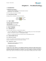
CHAPTER 6 - TROUBLESHOOTING .................................................................................................. 39
1 - DIAGNOSTICS.............................................................................................................................. 39
1.1 - CD1-pm FAULT LEDs ............................................................................................................ 39
1.2 - FAULT RESET........................................................................................................................ 39
2 - FAULT FINDING............................................................................................................................ 39
2.1 - SYSTEM FAULT..................................................................................................................... 39
2.2 - NON STORED FAULTS ......................................................................................................... 39
2.3 - STORED FAULTS .................................................................................................................. 39
3 - OPERATING PROBLEMS............................................................................................................. 44
3.1 - MOTOR DOES NOT MOVE ................................................................................................... 44
3.2 - MOTOR SUPPLIED BUT NO TORQUE ................................................................................ 44
3.3 - SHAFT LOCKED, ERATIC OSCILLATIONS OR ROTATION AT MAXIMUM SPEED .......... 44
3.4 - DISCONTINUOUS MOTOR ROTATION WITH ZERO TORQUE POSITIONS..................... 44
3.5 - LOUD CRACKLING NOISE IN THE MOTOR AT STANDSTILL............................................ 44
3.6 - LOUD NOISE IN THE MOTOR AT STANDSTILL AND WHEN RUNNING ........................... 45
3.7 - SEQUENCE NOT EXECUTED .............................................................................................. 45
4 - SERVICE AND MAINTENANCE ................................................................................................... 45
APPENDIX ............................................................................................................................................ 46
1 - SERVO CONTROLLER STRUCTURE ......................................................................................... 46
2 - USE OF THE SERIAL LINK ........................................................................................................... 47
2.1 - OVERVIEW............................................................................................................................. 47
2.2 - INSTRUCTIONS LIST ............................................................................................................ 48
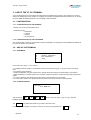
3 - USE OF THE VT 100 TERMINAL .................................................................................................. 51
3.1 - CONFIGURATION.................................................................................................................. 51
3.2 - USE OF THE TERMINAL ....................................................................................................... 51
3.3 - FAULT DISPLAY .................................................................................................................... 53
6
Chapter 1 – General description
CD1-pm - User manual
Chapter 1 - General description
1 - INTRODUCTION
Series CD1-pm Profibus positioners are PWM servo amplifiers for the control of AC sinusoidal motors (brushless)
equipped with a position sensor.
The CD1-pm servo drive is available as a stand-alone single-axis block that includes all supplies and mains filter.
It is available in both mains operated versions 230 VAC and 400/480 VAC.
The CD1-pm positioner generates itself the positioning trajectory and is suited for axis positioning applications. Up
to 128 control sequences including axis homing, absolute or relative displacement, speed profile running,
electronic gearing and torque regulation can be programmed and combined in order to solve various applications.
The sequence chaining capability allows to define macro-sequences for complex applications: several control
sequences can be linked together in order to be automatically executed one after the other. The control
sequences are pre-programmed. So, the application programmation simply consists in initializing the sequences
parameters with the desired values. A control sequence can then be selected by using the programmable logic
inputs and its execution is started by using the START logic input. The CD1-pm positioner can operate in standalone mode or in connection with a host controller (PROFIBUS mode).
The selection of the various operation modes is made by means of micro-switches accessible by the operator.
1.1 – PROFIBUS MODE WITH SOFTWARE ADDRESSING
This mode is activated by the 00 micro-switches selection.
This operation mode is fully compliant with the CD1-p positioner.
The positioner Profibus address is saved into a non volatile memory (EEPROM). This EEPROM can be modified
via Profibus (message Set_Slave_Add) by a Profibus master of class 2. The new address will be automatically
saved.
1.2 – PROFIBUS MODE WITH HARDWARE ADDRESSING
This mode is activated by the 01 to 7D micro-switches selections (Profibus address valid for one slave: 3 to 125).
In this mode, the drive address is defined by the micro-switches status and not by the serial link or by Profibus.
The address modification via Profibus is still possible but the address taken into account at the next power up is
always the one defined by the selection micro-switches.
1.3 – STAND-ALONE MODE
This mode is activated for the 7E and 7F combinations of the selection micro-switches:
The 7E combination corresponds to the stand-alone mode with VT100.
The 7F combination corresponds to the stand-alone mode without VT100.
In this mode, the Profibus is not used. The positioner operation is managed by the inputs START, STOP, IN1 to
IN6 as well as by the outputs SEQ, POS, SPEED, OUT1 to OUT4.
The ENABLE input enables/disables the positioner. The positioner cannot be enabled/disabled via the serial link
RS-232 or by the Profibus. Consequently, the positioner adjustment phase (autophasing, autotuning,
cogging torque acquisition ...) must not be made in stand-alone mode. In stand-alone mode, the brake delay
time with regard to the enabling/disabling is not possible either.
Chapter 1 - General description
7
CD1-pm - User manual
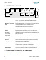
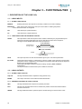
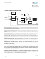
2 - ARCHITECTURE OF A POSITIONER
Logic I/0s
Sequence
selection
Profibus-DP
interface
Trajectory
generator
Position
loop
Speed
loop
Current loop
Position
feedback
Speed
feedback
Current
feedback
Motor
Position
sensor
Electric motor
Electric device that transforms electrical energy into a mechanical movement.
This transformation is often made by means of a current commutation.
Generally, the movement is a rotation but there are also linear motors.
Motor
Electric motor which current commutation is made by mechanical brushes.
Brushless or synchronous
motor
Electric brushless motor. The current commutation is electronically made and
requires a position sensor (resolver, encoder, Hall sensor...).
Resolver
Absolute position sensor over one revolution. The resolver is often used
together with brushless motors because of its robustness.
Encoder
Incremental or absolute position sensor. The encoder is used together with
brushless motors for its accuracy.
Amplifier
Servo drive
Electric device for the control of electric motors. It also includes a current
regulator, a speed servo control and, a position servo control.
Current loop
Current regulator
Used for the motor current control. The motor torque is generally proportional
to the current amplitude.
Speed loop
Speed regulator
Allows the motor speed control with a speed input command.
Position loop
Position regulator
Allows the motor position control.
Positioner
Positioner with position loop and trajectory generator that allows positioning.
Trajectory generator
Generates a speed profile (acceleration, step speed, deceleration) that allows
positioning (start position -> arrival position).
Fieldbus
Digital link that allows real time data exchange between various electric
devices. The characteristic of field busses is their high protection and fault
correction level as well as a predictable communication time.
Profibus
Fieldbus initially defined by Siemens®. This bus is widely used in automation.
Enabled/disabled
(Servo On/Off)
When a motor is enabled, it is controlled by the positioner and the servo
loops are operating. When disabled, its rotation is free and there is no current
in the motor.
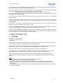
3 - OTHER DOCUMENTS REQUIRED FOR THE COMMISSIONING
♦
♦
8
" CD1-pm Profibus positioner Installation Manual".
" CD1-pm Profibus Communication Profile".
Chapter 1 – General description
CD1-pm - User manual
Chapter 2 - Commissioning
!
WARNING
During the machine adjustments, some drive connection or parametrization errors may involve
dangerous axis movements. It is the user's responsibility to take all necessary steps in order to
reduce the risk due to uncontrolled axis movements during the operator's presence in the
concerned area.
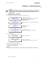
1 – COMMISSIONING OVERVIEW
The various stages of a first positioner commissioning are described below:
MOTOR ADJUSTMENT
(chapter 2 section 7)
SERVO CONTROL ADJUSTMENT
(chapter 2 section 8)
CONFIGURATION
(chapter 4 section 2)
PROFIBUS COMMUNICATION
(PROFIBUS communication profile
manual)
- Current regulator adjustment.
2
- Definition of the current limitations and of the I t protection.
- Adjustment of the motor control parameters.
- Speed limitation definition.
- Rotation direction.
- Adjustment of the servo control parameters according to the
load.
- Definition of the resolution.
- Limit switches.
- Following error.
PROFIBUS operation mode :
- Communication start between PLC and positioner.
Both operation stages are:
PROGRAMMATION
(chapter 4 section 3)
PROFIBUS OPERATION
(PROFIBUS communication profile
manual)
- Sequences programmation.
PROFIBUS operation mode :
- "Operational" phase: sequences execution by Profibus.
The positioner parameters are accessible via:
- the serial link and the PC parametrization software,
- or by the PKW of the PROFIBUS DP.
CAUTION !
Do not make the drive parametrization by means of both PC software and Profibus at the same time.
Chapter 2 - Commissioning
9
CD1-pm - User manual
2 – INSTALLATION OF THE PC SOFTWARE
The Visual Drive Setup software is PC compliant under Windows® 1 and allows an easy parametrization of the
CD1-pm amplifiers.
Please see our website www.infranor.fr for downloading the "Visual Drive Setup" software.
3 - CHECKING THE POSITIONER HARDWARE CONFIGURATION
The standard amplifier configuration is adjusted to MAVILOR motors (resolver sensor with transformation ratio =
0.5). For the adjustment to other motor types, please see "CD1-pm - Installation Guide".
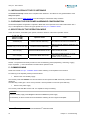
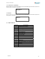
4 - SELECTION OF THE OPERATION MODE
A DIP micro-switch, accessible by the operator, allows the selection of the various operation modes.
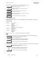
7 6 5 4 3 2 1
(Switch 7 = MSB
Switch 1 = LSB)
Operation mode
X0000000 (00)
Profibus software addressing
This mode is compliant with the CD1-p drive
Drive address is stored into the EEPROM
X0000001 (01) to X1111101 (7D)
Profibus hardware addressing
Profibus mode with hardware addressing via
"DIP" switch
X1111111(7F)
Stand-alone Mode without VT100
X1111110(7E)
Stand-alone Mode with VT100
Note
Drive used in Positioner mode via inputs
START, STOP, IN1 to IN6
Drive used in Positioner mode via inputs
START, STOP, IN1 to IN6
Possible use of a VT100 terminal
X : Cursor unused.
Remark : The positioner automatic procedure for the commissioning phase (autophasing, autotuning, cogging
torque acquisition ...) cannot be started in the stand-alone operation mode .
5 - COMMISSIONING
Please see manual "CD1-pm - Installation Guide" before switching on the amplifier for the first time.
For switching on the amplifier, please proceed as follows:
•
Switch on the +24V auxiliary supply:
The red front panel LED "ERROR" must be unlit and the red front panel LED "AP" must be lit ("Undervolt." error
displayed).
The AOK relay contact (pins 1 and 2 of X4) is closed. It is then possible to control the power ON relay.
•
Switch on the power supply:
The red front panel LED "AP" must be unlit : the amplifier is ready for enabling.
CAUTION !
The 24 V auxiliary supply must always be switched on before the power supply.
It is mandatory to wait for at least 30 seconds between switching off and on again the amplifier.
1
Windows® is a registered trade mark of MICROSOFT® CORPORATION
10
Chapter 2 - Commissioning
CD1-pm - User manual
6 - STARTING THE "VDSETUP" SOFTWARE
•
•
Connect the serial link RS232 between PC and amplifier.
Switch on the amplifier and start the Visual Drive Setup software on the PC, under WINDOWS®.
If the message No serial communication found is displayed on the screen, click on OK and check the following
points:
o
o
o
The amplifier must be on,
The correct RS232 connection between amplifier and PC,
The correct software configuration (Com.port, ...).
For the parametrization of the amplifier via the Visual Drive Setup software, set all DIP micro-switches at position
OFF (address 00).
7 - MOTOR ADJUSTMENT
7.1 - CONFIGURATION OF THE SENSOR TYPE
The configuration of the sensor type is software selectable and saved in the amplifier EEPROM.
The amplifier is configured as standard for a resolver sensor. For motors equipped with an encoder, please
proceed as follows:
♦ Select the appropriate encoder type in the Resolver & Encoder input configuration menu.
♦ Select Encoder feedback and confirm this selection.
♦ Then enter the Motor encoder Resolution value in the Servo Motor module.
If the motor is equipped with Hall effect sensors, check that the ENABLE input is not activated and the amplifier is
on, before moving manually the motor over one revolution or one pole pitch on linear motors. If the HES error is
displayed, switch off the amplifier and check the following points before switching it on again:
♦
♦
♦
The Hall effect sensors (HES) must be correctly connected on the amplifier X3 connector (if 60° Hall sensor
types are used, check the various wiring combination of the HES signals for finding the right wiring order).
Check for the correct supply voltage of the Hall sensors.
Check for the correct value of the Motor encoder Resolution parameter.
If the motor Hall sensors do not work correctly, select the appropriate incremental encoder type (Incremental
Encoder without HES) in the Feedback configuration menu and start the amplifier commissioning with this
configuration.
If the motor used is equipped with an absolute Sin/Cos encoder over one revolution (Heidenhain ERN 1085 or
compliant), check that the ENABLE input is not activated and the amplifier on. Then move manually the motor
over one revolution. If the HES error is displayed, switch off the amplifier and check the following points before
switching it on again:
♦
♦
♦
The commutation channels of the Sin/Cos encoder must be correctly wired on the amplifier X3 connector.
Check for the correct supply voltage of the Sin/Cos encoder.
Check for the correct value of the Motor encoder resolution parameter.
Perform the Save parameters to EEPROM procedure before switching off the amplifier in order to save the
sensor configuration.
Chapter 2 - Commissioning
11
CD1-pm - User manual
7.2 - SELECTION OF THE MOTOR TYPE
THE MOTOR USED IN THE APPLICATION IS CONTAINED IN THE MOTOR LIST OF THE
PARAMETRIZATION SOFTWARE.
Select, in the motor list, the motor used in the application.
The motor selection will start the automatic calculation of the current loop parameters.
Check that the values of the parameters Max. current and Rated current are compliant with motor and amplifier.
If necessary, modify them according to the motor and amplifier specifications.
The parameter Max current defines the maximum output current value of the amplifier. It may vary between 20 %
and 100 % of the amplifier current rating.
The parameter Rated current defines the limitation threshold of the amplifier output RMS current (I2t).
It can vary between 20 % and 50 % of the amplifier current rating.
If the Incremental encoder without HES sensor configuration is selected, start a motor phasing (Phasing)
procedure.
The motor phasing can be launched either in the control window of the VISUAL DRIVE SETUP software, via the
PROFIBUS fieldbus, or via the Enable input in stand-alone mode.
THE MOTOR USED IN THE APPLICATION IS NOT CONTAINED IN THE MOTOR LIST OF THE
PARAMETRIZATION SOFTWARE.
Select the New Motor function and follow the instructions.
7.3 - ENCODER COUNTING PROTECTION
When servo motors are equipped with an encoder, any error in the encoder pulse counting generates an error in
the position measurement of the rotor and may involve uncontrolled motor movements that can be dangerous for
both operator and machine. The encoder counting protection of the CD1-pm amplifier range allows the detection
of pulse counting errors and immediately disables the amplifier for reasons of security.
The encoder counting protection checks that the number of encoder pulses between to successive Z marker
pulses (or R reference signals) is equal to the value of the Motor encoder resolution parameter multiplied by the
one of the Zero mark pitch parameter. The encoder counting protection also checks that the encoder pulse
frequency is lower than 1,5 times the maximum encoder frequency. The maximum encoder frequency is
calculated in the amplifier according to the value of the Motor encoder resolution and Maximum speed
parameters.
The value of the Motor encoder resolution parameter defines the number of encoder pulses (or encoder signal
periods) per motor revolution (for a rotary motor) or per motor pole pairs (for a linear motor).
The value of the Zero mark pitch parameter defines the number of motor revolutions (for a rotary motor) or of
motor pole pairs (for a linear motor) between two successive Z marker pulses (or R reference signals).
With a rotary motor, the Zero mark pitch parameter is generally equal to 1 because the encoder has got one Z
marker pulse (or one R reference signal) per motor revolution.
On a linear motor with only one marker pulse over the whole motor travel, the Zero mark pitch parameter must
be defined at 15. In this case, the encoder counting protection checks that the measured encoder position has still
got the same value when the marker pulse is activated (no drift in the position measurement).
Note: In the Incremental encoder without HES configuration, the motor phasing procedure (Phasing) must be
renewed after the release of a Counting error because the current rotor position reference for the motor
commutation is not correct.
12
Chapter 2 - Commissioning
CD1-pm - User manual
7.4 - PARAMETER ADJUSTMENT FOR A LINEAR MOTOR
The Motor encoder resolution parameter is calculated as follows:
N
S
N
S
N
S
Motor magnets
Pole pitch
Motor pole pitch (mm)
Motor encoder resolution = 1000 x
Encoder signal pitch (µm)
!
1 encoder signal pitch = 4 counting increments
The value of the motor Maximum speed parameter in rpm is calculated as follows:
1000
Max. speed (rpm) = 60 x
x max. motor speed (m/s)
Motor pole pitch (mm)
The linear speed value in m/s is calculated as follows:
Linear speed (m/s) =
Motor speed (rpm)
x
Motor pole pitch (mm)
60
1000
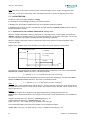
7.5 - MAXIMUM APPLICATION SPEED
The parameter Max. speed defines the maximum speed at which the amplifier can control the motor.
This parameter can be:
•
lower than or equal to the maximum motor speed,
•
slightly higher than the maximum motor speed in the application (20%). This margin allows a speed
overshoot that avoids the position loop saturation (position following). This margin can be as small as
possible when using a high bandwidth or at low acceleration.
The speed set point value for the sequences and for the manual movements (positioning and jog) are saved in %
with regard to the Max. speed parameter value. So, when the Max. speed parameter value is changed, all
speed set point values are scaled accordingly.
7.6 - CONFIGURATION OF THE THERMAL SENSOR
According to the selected position feedback sensor of the motor, the thermal sensor is entering either the X1
connector (resolver) or the X3 connector (encoder).
7.6.1 – SELECTION OF THE SENSOR TYPE
The motor can be equipped either with a CTN sensor (ohmic resistance = decreasing temperature function) or
with a CTP sensor (ohmic resistance = increasing temperature function).
Check that the selected thermal sensor type actually corresponds to the sensor type mounted on the application
motor.
7.6.2 – TRIGGERING THRESHOLD ADJUSTMENT
Enter the sensor ohmic value (kOhm) corresponding to the required temperature value for the release of the
Motor overtemperature protection, according to the manufacturer's specifications.
7.6.3 – WARNING THRESHOLD ADJUSTMENT
Enter the sensor ohmic value (kOhm) corresponding to a warning temperature value.
When the warning temperature is reached, the red front panel LED "ERROR" is blinking.
Chapter 2 - Commissioning
13
CD1-pm - User manual
Note: When using a CTN sensor, the warning ohmic value will be higher than or equal to the triggering ohmic
value.
When using a CTP sensor, the warning ohmic value will be lower than or equal to the triggering ohmic value.
7.7 - I2t PROTECTION
2 selection modes are available: Fusing or Limiting.
It is advisable to use the Fusing mode during commissioning phases.
In Fusing mode, the amplifier is disabled when the current limitation threshold is reached.
In Limiting mode, the motor current is only limited at the value defined by the Rated current parameter when the
limitation threshold is reached.
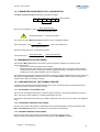
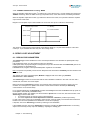
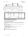
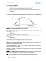
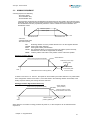
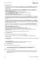
7.7.1 - OPERATION OF THE CURRENT LIMITATION IN "Fusing" mode
When the amplifier output RMS current (I2t) reaches 85 % of the rated current, the red amplifier front panel LED
"ERROR" is blinking. If the RMS current (I2t) has not dropped below 85 % of the rated current within 1 second, the
2
I t error is released and the amplifier disabled (otherwise, the blinking is inhibited).
When the amplifier output RMS current (I2t) reaches the rated current value, the I2t limits the amplifier output
current at this value.
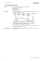
Diagram of the amplifier output current limitation in an extreme case (motor overload or shaft locked):
Amplifier output current
t1 = Blinking
Max. current
t2 = Current limitation
2
t3 = I t error
Rated current
1 second
time
t0
t1
t2
t3
The maximum current duration before release of the blinking display is depending on the value of the parameters
Rated current and Max. current. This value is calculated as follows:
T dyn (second) = t1-t0 = 3,3 x [ rated current (A) / max. current (A)]2
The maximum current duration before limitation at the rated current is also depending on the value of the Rated
current and Maximum current parameters. This value is calculated as follows:
T max (second) = t2-t0 = 4 x [rated current (A) / max. current (A)]
2
NOTE 1
When the "Max. current / Rated current" ratio is close to 1, the Tdyn and Tmax values given by the formula above
are quite below the real values. But this formula remains very precise as long as the "Max. current / Rated current"
ratio is higher than 3/2.
NOTE 2
The amplifier I2t signal can be displayed on the digital oscilloscope by selecting the I2t signal in the
2
Channel menu. The threshold values of the I t signal, for the protection mode described above, are calculated as
follows:
Triggering threshold of the Idyn signal (%) = [Rated current (%)]2 / 70
Current limitation threshold (%) = [Rated current (%)]2 / 50
Rated current (%) = 100 x Rated current (A) / amplifier current rating (A)
The corresponding RMS current value of the amplifier can be calculated as follows:
Amplifier RMS current (A) = [I2t signal value (%) x 50]1/2 x amplifier current rating (A) / 100
14
Chapter 2 - Commissioning
CD1-pm - User manual
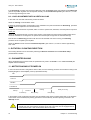
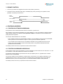
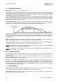
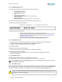
7.7.2 - CURRENT LIMITATION IN "Limiting" MODE
When the amplifier output RMS current (I2t) reaches 85 % of the rated current, , the red amplifier front panel LED
"ERROR" is blinking. When the RMS current (I2t) drops below 85 % of the rated current, the blinking is inhibited.
When the amplifier output RMS current (I2t) reaches the rated current value, the I2t protection limits the amplifier
output current at this value.
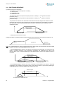
Diagram of the amplifier output current limitation in an extreme case (motor overload or shaft locked):
Amplifier output current
t1 = Blinking
t2 = Current limitation
Max. current
Rated current
time
t0
t1
t2
The maximum current duration before release of the blinking display (t1 - t0) and before limitation at the rated
current (t2 - t0) is calculated the same way as in the "Fusing" mode.
8 - SERVO LOOP ADJUSTMENT
8.1 - REGULATOR PARAMETERS
The Autotuning procedure identifies the motor and load specifications and calculates the speed/position loop
parameters.
In P and PI speed mode, only the speed loop gains are calculated.
2
In PI speed mode, the proportional gain of the position loop is also calculated. But the Feedforward gains of the
position regulator are all initialized at 0.
In Position mode, all gains of both speed and position regulators are calculated.
Note: The position loop stability can be tested in PI² speed mode because the Feedback gains are identical to the
Position mode.
The operator can select a bandwidth (Low, Medium or High) as well as the filter type (standard,
antiresonance or max. stiffness).
The Autotuning procedure can be executed with the motor disabled or enabled. In the case of an axis with a
vertical load, see section 8.2 of this chapter.
Before executing the Autotuning procedure, check that the motor shaft is free and that its rotation over one
revolution is not dangerous for operator and machine. Check that the brake is released (the Autotuning
command does not control the brake).
For a complete adjustment, the Autotuning procedure must always be executed in Position mode (at power on,
the amplifier is automatically in Position mode).
But the amplifier position loop stability can also be tested in Speed mode. In this case, after the execution of the
Autotuning procedure in PI² mode:
•
check that the motor is correctly running in both directions,
•
check the response at a small displacement without Idc saturation (oscilloscope function).
In case of loud noise in the motor at standstill or when running, check the rigidity of the mechanical transmission
between motor and load (backlashes and elasticities in motor and couplings).
If required, start a new Autotuning procedure by selecting a lower bandwidth.
If the instability remains, start a new Autotuning procedure by activating the Antiresonance filter. If necessary,
adjust more accurately the loop response stability by adjusting the stability gain.
Chapter 2 - Commissioning
15
CD1-pm - User manual
If the Autotuning procedure was executed in PI² mode, when the Position mode was selected, the Feedforward
gains of the position regulator must be adjusted manually. Set the Feedforward speed 1 gain value at 1, in order
to avoid a high following error value.
8.2 - LOOP ADJUSTMENT WITH A VERTICAL LOAD
In the case of an axis with vertical load, proceed as follows:
Select the Limiting current limitation mode.
Initialize the speed loop gains corresponding to the unloaded motor (execute therefore the Autotuning procedure
with the motor uncoupled from its mechanical load).
Couple the motor with its load. If possible, make a control in speed mode; otherwise, close the position loop with a
stable gain.
Select the PI² speed mode and move the axis by means of the speed input command until a stall position where
one motor revolution is not dangerous for operator and machine (far enough from the mechanical stops).
Execute then the Autotuning procedure with the motor at standstill. If the axis is moving, the Autotunig
procedure is not accepted by the amplifier.
Select the Position mode and set the Feedforward speed 1 gain value at 1, in order to avoid a high following
error value.
9 - ROTATION / COUNTING DIRECTION
The counting direction can be reversed by selecting the Reverse movement in the Visual Drive Setup
parametrization software.
10 - PARAMETER SAVING
When all adjustments have been made, the parameters may have to be stored in a non volatile EEPROM (the
amplifier must be disabled).
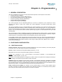
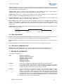
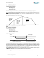
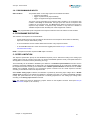
11 - MOTOR PHASING AT POWER ON
In the Incremental encoder configuration without HES, the motor Phasing procedure is executed according to the
following diagram at each amplifier power up (standalone mode) :
AOK
Power On
ENABLE
PHASING OK
Start up
End start up
Ready for running
Phasing
Power on
Start phasing
End phasing
In the Profibus mode, the phasing procedure must be started by the master controller (PNU 896). In the Software
control mode via the serial link, the phasing procedure must be started by the Motor phasing command in the
VDSetup window.
!
16
In the case of an axis with unbalanced load (constant torque due to the gravity effect on a
vertical axis), the motor phasing procedure is not valid. The motor must be equipped with an
incremental encoder + HES or an absolute Sin/Cos encoder.
Chapter 2 - Commissioning
CD1-pm - User manual
Remark: In the Incremental encoder configuration without HES, the motor Phasing procedure must be carried out
again after a Feedback fault release or a Counting fault release. The motor Phasing procedure must also be
carried out again after the modification of the motor or the encoder parameter value.
- The analog output on the X2 connector can be configured in the Setup menu of the VISUAL DRIVE SETUP
software in order to get the Phasing OK output signal (output voltage from 0 V to 10 V when the motor phasing is
OK) .
- In the Profibus mode, the Phasing OK can be checked by the master controller (PNU 897).
- In the Software control mode via the serial link, the state of the Phasing OK output is displayed in the main
VDSetup window.
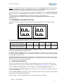
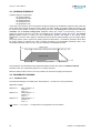
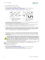
12 - INCREMENTAL ENCODER OUTPUTS
The incremental encoder outputs are two pulse channels A and B in quadrature and one Z marker pulse per
revolution.
A
A
t
B
t
B
t
CW rotation
(motor shaft front view)
t
CCW rotation
(motor shaft front view)
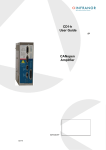
The Output encoder resolution is selected according to the table below:
Maximum motor speed (rpm)
up to 1600
Encoder output resolution (ppr)
512 to 16384
up to 3200
up to 6400
up to 12800 up to 25000
512 to 8192 512 to 4096 512 to 2048 512 to 1024
The resolution value defined in the Output encoder resolution parameter can be divided by 2, 4 or 8 by
selecting the Resolution division ratio parameter.
The Output encoder deadband parameter introduces a deadband at standstill around the current resolver
position in order to avoid oscillations of +/- 1 encoder edge on channels A and B. The value of 4095 corresponds
to 1/16 revolution of the motor shaft.
The Zero pulse origin shift parameter allows the shifting of the marker pulse position on channel Z with regard to
the resolver zero position. The value 32767 corresponds to one revolution of the motor shaft. The marker pulse
width is equal to ¼ of the A and B channels period.
13 – POSITION LOOP SETUP
The servo motor position loop can be closed by the motor feedback sensor or with the second position sensor
mounted on the load. In the case of the second position sensor feedback, please see section 14.1 of this chapter.
Open the "Position scaling parameters" window accessible in the "Positioner Application Setup" menu.
Check that "Enable second sensor feedback" is not selected, in order to use the motor position sensor (resolver
or encoder) for feedback.
Set the “Position resolution” parameter according to the desired position scaling of the load in order to display
the position in the load units as described below:
Position resolution = number of desired load position increments for one motor revolution
Chapter 2 - Commissioning
17
CD1-pm - User manual
Ex: one motor revolution = 3.302 mm on the load, if the load position must be displayed in mm with a resolution of
1µm. Choose Position resolution = 3302, Decimal number = 3 and Unit = mm.
The servo loop stability is not affected by the Position Resolution parameter value.
Set at 0 the value of the “Position deadband” parameter. This parameter is only useful in applications with high
transmission backlashes or applications with high axis frictions. In those cases, when the position error value at
standstill is lower than the value of the “Position deadband” parameter, the proportional gain of the position loop
is set at 0.
14 – APPLICATIONS WITH THE SECOND SENSOR INPUT
The CD1-pm amplifier has got 2 position sensor inputs : one for a resolver and another for an encoder. The
position sensor input which is not used for the motor position feedback (encoder or resolver) is called Second
Position Sensor input. The Second Position Sensor input can be used for closing the drive position loop if a
position sensor is mounted on the motor load . The Second Position Sensor input can also be used for an
electronic gearing application.
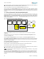
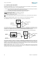
14.1 – SECOND POSITION SENSOR FEEDBACK
Trajectory
generator
Position
loop
Enable
nd
2 sensor
Speed
loop
Current loop
Motor
Load
Motor
feedback
Load
position
Scaling factor
Num / Den
Resolver sensor feedback for the motor, and TTL incremental encoder for the second sensor is the default
configuration.
Select the required position sensor configuration in the "Resolver & encoder Input configuration" window
accessible in the "Setup" menu.
Open the "Position scaling parameters" window accessible in the "Positioner Application Setup" menu.
Select "Enable second sensor feedback" to use the second position sensor (encoder or resolver) for closing the
drive position loop. When this command is not selected, the drive position loop is using the motor position sensor
(resolver or encoder) for feedback.
Set the “Position resolution” parameter according to the desired position scaling of the load in order to display
the position in the load units as described below:
Position resolution = number of desired load position increments for one motor shaft revolution.
Enter the desired "Decimal" number and the "Unit" for the position display.
Ex: one motor revolution = 3.302 mm on the load, if the load position must be displayed in mm with a resolution of
1µm, choose Position resolution = 3302, Decimal number = 3 and Unit = mm.
Remark: In the second sensor feedback configuration, the servo loop stability is affected by a wrong Position
resolution parameter value.
Set at 0 the value of the “Position deadband” parameter. This parameter is only useful in applications with high
transmission backlashes or applications with high axis frictions. In those cases, when the position error value at
standstill is lower than the value of the “Position deadband” parameter, the proportional gain of the position loop
is set at 0.
18
Chapter 2 - Commissioning
CD1-pm - User manual
Open the "Second Sensor" window accessible in the "Positioner Application Setup" menu.
Adjust the "Position scaling factor" (numerator / denominator) according to the desired load position scaling and
the current load sensor resolution as described below:
- For an encoder sensor type on the load:
Position scaling factor Numerator = "Position resolution" parameter value (see “Position scaling parameters”
window).
Position scaling factor Denominator = 4 x number of encoder pulses/channel for one motor shaft revolution.
- For a resolver sensor type on the load:
Position scaling factor Numerator = "Position resolution" parameter value (see “Position scaling parameters”
window).
Position scaling factor Denominator = 65536 x number of resolver shaft revolution for one motor shaft revolution.
!
REMARK:
If the calculated Numerator and Denominator values exceed the parameters max. value
(65535), they must be scaled in order to get the same ratio (Numerator / Denominator) or to be
as close as possible to the theoretical value: scaled Numerator / scaled Denominator =
calculated Numerator / calculated Denominator.
Select "Reverse position" to reverse the counting direction of the second position sensor if required.
When the second position sensor is a SinCos encoder type, select "Pulse interpolation".
Enable the amplifier and check that the motor and load positions are stable. If the motor is moving (and then the
following error is released), the sign of the load position feedback is not correct. In this case, select the “Reverse
position” command in the “Second sensor” window.
14.2 - ELECTRONIC GEARING APPLICATION
Master
position
Scaling factor
Num / Den
Position
loop
Speed
loop
Current loop
Motor
Motor
feedback
Electronic gearing applications require the use of the second amplifier position sensor for measuring the
displacements of the master axis.
If the motor is equipped with a resolver, select the encoder type for the input of the second sensor in the
"Resolver & encoder Input configuration" window accessible in the "Setup" menu.
Open the "Position scaling parameters" window accessible in the "Positioner Application Setup" menu.
Check that "Enable second sensor feedback" is not selected.
Set the “Position resolution” parameter according to the desired position scaling of the load in order to display
the position in the load units as described below:
Position resolution = number of desired load position increments for one motor shaft revolution
Enter the desired "Decimal" number and the "Unit" for the position display.
Ex: one motor revolution = 3.302 mm on the load, if the load position must be displayed in mm with a resolution of
1µm, choose Position resolution = 3302, Decimal number = 3 and Unit = mm.
Chapter 2 - Commissioning
19
CD1-pm - User manual
Set at 0 the value of the “Position deadband” parameter. This parameter is only useful in applications with high
transmission backlashes or applications with high axis frictions. In those cases, when the position error value at
standstill is lower than the value of the “Position deadband” parameter, the proportional gain of the position loop
is set at 0.
Open the "Second Sensor" window accessible in the "Positioner Application Setup" menu.
Adjust the "Position scaling factor" (numerator / denominator) according to the desired gearing ratio as
described below:
- For an electronic gearing application with an encoder sensor type on the master axis,
Gearing ratio = Gearing numerator / Gearing denominator = Motor shaft speed / Master encoder shaft speed.
Position scaling factor Numerator = ("Position resolution" parameter value) x Gearing numerator.
Position scaling factor Denominator = (4 x master encoder resolution) x Gearing denominator.
- For an electronic gearing application with a resolver sensor type on the master axis,
Gearing ratio = Gearing numerator / Gearing denominator = Motor shaft speed / Master resolver shaft speed.
Position scaling factor Numerator = ("Position resolution" parameter value) x Gearing numerator.
Position scaling factor Denominator = 65536 x Gearing denominator.
!
REMARK:
If the calculated Numerator and Denominator values exceed the parameters max. value (65535),
they must be scaled in order to get the same ratio (Numerator / Denominator) or to be as close as
possible to the theoretical value: scaled Numerator / scaled Denominator = calculated Numerator /
calculated Denominator.
When the second position sensor is a SinCos encoder type, select "Pulse interpolation".
Enable the amplifier and select “Enable gearing” in the “Software control” window. Check that the slave axis
actually follows the displacement of the master axis with the correct reduction ratio.
If the motion direction is not correct, select the “Reverse position” command in the “Second sensor” window.
If there is a loud noise in the motor during the axis motion, set at 0 the “Feedforward acceleration” gain. If using
a SinCos master encoder, check also that the “Pulse interpolation” command is enabled in the “Second
sensor” window.
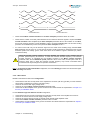
15 - COGGING TORQUE COMPENSATION
The cogging torque in brushless permanent magnet rotary motors or the cogging force in brushless permanent
magnet linear motors results from the interaction between the rotor magnets and the stator slots. This disturbance
is due to the difference of reluctance between the copper of the windings and the iron of the stator teeth. For a
given motor, the cogging can be easily evaluated by simply moving the motor manually when the amplifier is
disabled. The Cogging compensation option available in the CD1 amplifier range allows to cancel the motor
cogging effects for specific applications where torque accuracy or force accuracy higher than 1 % is required.
CD1 amplifiers must be factory set for getting the cogging compensation option (reference CD1pm-U/I–CT).
Check for the presence of the cogging compensation option (CT-CD1) in the VDSetup Hardware option menu. In
this case, the Cogging torque compensation menu can be selected in the Servo loop module.
!
For a brushless motor equipped with an incremental encoder, the Cogging torque compensation is
only available if the encoder is providing one marker pulse per motor revolution.
The cogging torque acquisition procedure is started by means of the Start button. The motor must be uncoupled
from its load and the shaft must not be disturbed during the procedure. Before starting the acquisition, switch the
drive on manual mode and then disable it (Drive control = Off). Then, start the Auto-tuning procedure with
following selections: Regulator = PI², Filter = Max. stiffness and Bandwidth = High. At the end of the cogging
torque acquisition procedure, the amplifier parameter file (*.PAR) can be uploaded again in order to recover the
initial adjustments.
20
Chapter 2 - Commissioning
CD1-pm - User manual
The Enable cogging torque compensation function allows the commissioning of the motor cogging torque
compensation. This function is saved in the amplifier EEPROM.
The Save cogging torque data into a file function allows to store in a PC the cogging torque value
corresponding to a motor after the acquisition procedure (*.COG file).
The Write cogging torque data into the drive function allows to upload in the amplifier the cogging torque value
corresponding to a motor, if this value has previously been stored in the PC (*.COG file).
!
For a brushless motor equipped with an incremental encoder, the Cogging torque
compensation is only available if the encoder is providing one marker pulse per motor
revolution.
Note 1:
The motor cogging torque value is checked at the amplifier power up. If it contains some errors (storage problems
in the amplifier memory), the EEPROM error is displayed and the Enable cogging torque compensation
function is disabled.
Note 2:
When exchanging an amplifier on an axis, the file of the adjustment parameters (*.PAR) as well as the cogging
torque file (*.COG) corresponding to the motor must be uploaded once again in the amplifier.
Note 3:
When exchanging the motor or when disassembling the resolver sensor, the acquisition procedure must be
renewed.
Chapter 2 - Commissioning
21
CD1-pm - User manual
Chapter 3 – FUNCTIONALITIES
1 - DESCRIPTION OF THE LOGIC I/Os
1.1 - LOGIC INPUTS
1.1.1 - GLOBAL LOGIC INPUTS
ENABLE
Enabling authorized. This signal is a necessary condition for the motor enabling.
INDEX/CLR
Index input for the axis homing. This input can be used for resetting the position
counter when this function is configured.
FC+
Limit switch input, positive direction.
FC-
Limit switch input, negative direction.
1.1.2 - LOGIC INPUTS FOR THE SEQUENCE CONTROL
START
This input allows to start the sequence which number is defined by the programmable inputs.
The level of this input will be taken into account after the end of the former sequence.
This signal can be disabled before the end of the sequence.
6 ms minimum
Combination of
the logic inputs
1,5 ms minimum
START
4 ms minimum
STOP
This input stops the motor with the deceleration given by the JOG motion parameters.
IN1 to IN6
These inputs allow to define, in natural binary code, the number of the sequence to be executed
("Sequence control" configuration). The activation of the START input will execute the sequence
defined by the programmable inputs.
These inputs also allow to define a sequence starting condition ("Start condition"
configuration).
The sequence will be executed if the inputs condition is answered.
1.2 - LOGIC OUTPUTS
1.2.1 - GLOBAL LOGIC OUTPUTS
Amp OK
This signal indicates that the amplifier is ready (without error).
BRAKE
This output controls the motor brake activation/desactivation.
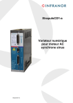
1.2.2 - SEQUENCE CONTROLLED LOGIC OUTPUTS
SEQ
This signal indicates that a sequence is presently executed.
POS
This signal is activated when the motor reaches the position and remains enabled until the
next motor movement.
SPEED
This signal indicates that the speed set point is reached during a movement of the motor.
22
Chapter 3- Functionalities
CD1-pm - User manual
Sequence 1 with
Tdec = 0 and Next = 2
Sequence 2
Delay time
POS
SEQ
SPEED
OUT1 to OUT4
Programmable logic outputs. These outputs are only operating during a programmed
sequence.
BEGIN :
Sequence
begin
SPEED :
Speed
reached
POS :
Pre-defined
position
reached
HOLD :
Arrival at
reference
position
END :
Sequence
over
t
Programmable status: "High" status - "Low" status - "Toggle" status.
Various triggering types: BEGIN, SPEED, POS, HOLD, END.
These outputs can be triggered only once per programmed sequence.
2 - LIMIT SWITCHES ADJUSTMENT
The limit switch inputs are inputs for a proximity sensor that stops the motor with maximum deceleration. When
both limit switches are correctly placed on the motor travel, they are a protection for the machine in case of
incorrect movement.
The limit switches are only defined according to the physical motor rotation. They are not depending on the
selected "rotation/counting direction".
For checking the limit switches:
- move the motor in one direction in speed mode,
- activate the limit switch which is located in the motion direction (artificially, if necessary),
- check that the motor is stopping,
- if the motor does not stop, the limit switches are reversed wired.
Check also in the opposite direction.
Notes
- The motor is stopped with maximum deceleration by a limit switch.
- Reminder: The limit switches are wired as "normally closed".
Chapter 3 - Functionalities
23
CD1-pm - User manual
3 - BRAKE CONTROL
•
The CD1-pm positioner is equipped with a brake control (made by transistor).
•
The brake control is activated (relay open) or disabled (relay closed) according to the positioner status
(disabled or enabled) as shown below.
Enable
command
Motor enabled
Brake OFF delay
Brake control
output
Brake ON delay
4 - PROFIBUS ADDRESS
4.1 - PROFIBUS SOFTWARE ADDRESSING
This operation mode is selected with all the DIP micro-switches on position OFF.
Each positioner of the network is identified by one single address (1 to 125). The positioner is delivered with the
default software address 126, which is not an operational address. This address must be modified before
putting the bus into operation.
The CD1-pm software address can be modified:
- by the serial RS-232 link (PC parametrization software). The new address must be saved in the EEPROM
and the positioner must be switched on again in order to get the new address operational;
- or by a Profibus class 2 master device. The address modification is only possible when the bus is not
running. In this case, the address will be automatically saved in the positioner EEPROM and will be
operational at the bus starting.
The identity number of the CD1-pm positioners under Profibus is 0x00C7.
4.2 - PROFIBUS HARDWARE ADDRESSING
In this operation mode, the CD1-pm address (1 to 125) is selected by means of the DIP micro-switches 1 to 7. DIP
micro-switches 1 is the LSB and DIP micro-switches 7 is the MSB.
The selected hardware address is operational at the CD1-pm amplifier power on, regardless of the software
address saved in the EEPROM.
The CD1-pm address can be modified by a Profibus class 2 master device. The address modification is only
possible when the bus is not running. In this case, the address will be automatically saved in the positioner
EEPROM. However, at the next CD1-pm power on, the selected hardware address is still operational.
The identity number of the CD1-pm positioners under Profibus is 0x00C7.
24
Chapter 3- Functionalities
CD1-pm - User manual
Chapter 4 - Programmation
1 – GENERAL DESCRIPTION
The CD1-pm amplifiers can get up to 128 pre-programmed sequences. Each sequence can be either :
•
a homing sequence (HOME) or
•
an absolute positioning sequence (ABSOLUTE) or
•
an incremental positioning sequence (RELATIVE) or
•
an electronic gearing sequence (GEARING) or
•
a speed profile sequence (SPEED) or
•
a torque control sequence (TORQUE).
The control sequences can be automatically linked up: as soon as a sequence is over, another one can be
executed. This allows to easily solve complex axis control applications by chaining several basic control
sequences.
The CD1-pm amplifiers have got 8 programmable logic outputs (triggering at the sequences execution) and 8
programmable logic inputs allowing to control a sequence start or stop. The logic inputs 1 to 6 are accessible on
the X2 connector while the logic inputs 7 and 8 are virtual and can only be activated via PROFIBUS. The logic
outputs 1 to 4 are connected on the X2 connector while the logic outputs 5 to 8 are virtual and can only be read
via PROFIBUS.
The programmation consists in initializing the sequence parameters with the desired values. A control sequence
can then be selected by using the programmable logic inputs activation and its execution is started by using the
START logic input. Any sequence execution can be stopped by using the STOP logic input.
In the Profibus operation mode, the positioner logic inputs (START, STOP, IN1 to IN6) can be activated either via
the PROFIBUS or by using the hardware inputs on the X2 connector. The inputs source configuration is saved in
the amplifier EEPROM. In the Profibus operation mode, all logic outputs (SEQ, POS, SPEED, OUT1 to OUT8)
can be read via PROFIBUS.
2 – POSITIONER CONFIGURATION
2.1 – POSITION SCALING
Position resolution: defines the number of position increments for one motor revolution (or one motor pole pitch
for a linear motor). The value range is between 128 and 65536 pts.
Decimal: number of decimals for the position display resolution (1, 2 or 3).
Unit: defines the unit used for the position display (maximum 4 characters).
Example: For a resolution of 4 mm / motor revolution, if the number of decimals = 3, the parameters are:
Resolution = 4000, Decimal = 3, Unit = mm.
Note: When one of these parameters is changed, all position values in the positioner are displayed according to
the new setting. The sequence set point values are also concerned.
Deadband: defines the deadband for the position controller. This parameter introduces a deadband at standstill
around the position loop setpoint. When the position loop error is lower than this parameter value, the position
loop proportional gain is set at 0. This parameter is reserved for specific applications with load backlashes and a
high level of dry frictions. The deadband is desactivated when the parameter is set at 0.
Enable second sensor feedback: the selection of this command allows to use the second position sensor
(encoder or resolver) for closing the drive position loop. When this command is not selected, the drive position
loop is using the motor position sensor (resolver or encoder) for feedback.
Chapter 4 - Programmation
25
CD1-pm - User manual
2.2 – POSITION LIMIT AND SAFETY
Following error threshold: defines the following error triggering threshold. It is important to correctly adjust this
value in order to get a good protection. It can be adjusted like follows:
1 - Make the motor rotate with the required operation cycles and measure the maximum following error threshold:
- either by means of the oscilloscope of the parametrization software,
- or by reducing the following error threshold value until the fault is triggered,
2 - Then set the following error threshold at this value plus a margin of 30 to 50 %.
Example: Adjustment of the following error threshold on an axis with:
Position resolution = 5000.
Maximum following error measured by oscilloscope = 164.
The threshold is set at 246 (margin = 50 %).
Note: In the PC parametrization software, if the number of decimals is set at 3, the value that must be entered is
0,246.
Following error detection mode: defines the mode of operation of the axis following error protection.
When Absolute is selected, the following error protection is operating as described below.
Following
error
threshold
Measured
position error
Position following
error
Comparator
Absolute
value
The measured position error value is continuously compared with the the following error threshold parameter
value. When the measured position error is exceeding the following error threshold, the position following error
is released. This configuration is used for applications requiring the smallest possible following error.
When Relative to dynamic model is selected, the following error protection is operating as described below.
Position
reference
Position loop model
Following
error
threshold
Theoretical
position error
+
Position following
error
Comparator
Absolute
value
Measured
position error
The measured position error value is continuously compared with the theoretical position error given by the
position loop model. When the difference is exceeding the following error threshold, the position following error
is released. In this configuration, when the position servo loop is adjusted to get the motor position continuously
lagging the reference position (applications for positioning without overshoot and with a large following error
value), any small anomaly in the actuator behaviour can be detected.
Software position limits + and -: this function is only active if the HOME sequence has been previously
executed. When the motor passes the software limit position value, it is stopped with a controlled braking. The
deceleration ramp value is given by the jog deceleration time.
26
Chapter 4 - Programmation
CD1-pm - User manual
2.3 – MANUAL MOVEMENTS
There are 2 types of manual motion:
- manual positioning: moving of the motor until a given position via the serial link.
- manual jog: continuous movement when the JOG command is activated.
(JOG+ for a movement in the positive direction and JOG- for a movement in the negative direction)
The motion profile parameters are:
- motion speed,
- acceleration time,
- deceleration time.
The parameters acceleration time and deceleration time define the time with regard to the maximum speed
parameter value. When the motion speed is lower than the maximum speed, the trajectory acceleration and
deceleration times are proportionally reduced.
Maximum speed
Motion speed
Acceleration time
Deceleration time
Remark : The JOG deceleration time parameter value is also used when the STOP input is activated.
2.4 – BRAKE CONTROL AND AMPLIFIER DISABLING
Brake ON delay: defines the time between the brake activation and the amplifier disabling according to the
following timing:
- brake ON (contact open),
- delay time,
- amplifier disabled.
The brake ON delay value must be higher than the brake response time.
Brake OFF delay: defines the time between the amplifier enabling and the brake desactivation according to the
following timing:
- amplifier enabling,
- delay time,
- brake OFF (contact closed).
The brake off delay value must be higher than the amplifier servo loop response time.
Note: The brake ON and OFF delays are not valid for the stand-alone operation mode.
ENABLE input desactivation and fault reaction defines the amplifier behaviour when the ENABLE input is
desactivated or when an amplifier fault is triggered :
-When Switch off is selected, the amplifier is immediately disabled and the motor is freewelling on ENABLE input
desactivation or on a fault reaction.
-When Stop with current limit is selected, the motor is first slowed down and then the amplifier disabled on
ENABLE input desactivation or a fault reaction.
Stop current limit defines the current limitation value when the motor is slowed down on ENABLE input
desactivation or a fault reaction. This current limit value is also used for the motor slow-down when the hardware
limit switches are activated.
Remark : The motor slow down with current limit is only possible when the following faults are triggered : Position
following error, I²t, Motor overtemperature, Fieldbus error. When the other amplifier faults are triggered, the
motor cannot be slowed down with current limit and the amplifier is immediately disabled.
Note: When the stopping with current limit operation is executed on ENABLE input desactivation or on a fault
reaction, the motor brake is activated at the end of the deceleration phase, when the motor is stopped.
Chapter 4 - Programmation
27
CD1-pm - User manual
2.5 – POSITIONING PROFILE
Speed profile: trapezoidal or S-curve shape selection.
Profile limit: when the Constant time profile limit mode is selected, for a small displacement, if the profile speed
cannot be reached, the motor acceleration and deceleration are modified in order to get the same acceleration
and deceleration times than the programmed profile. This selection allows to get a smooth positioning for small
displacements, however the displacement time is increased.
When the Constant slope profile limit mode is selected, for a small programmed displacement, if the profile
speed cannot be reached, the motor acceleration and deceleration are similar to the programmed acceleration
and deceleration values of the profile. This selection allows to get a faster positioning for small displacements,
however a position loop overshoot may occur.
Enable speed limitation: when this command is selected, the sequence speed values can be reduced according
to the PNU 714 value (in the Profibus operation mode) or the analog input voltage value on the X2 connector, as
shown below. The speed reduction is also applied for manual movements (Positioning and Jog).
Positioning sequence :
Speed
Programmed speed
Limited speed
Time
Enable speed modulation: when this command is selected, the programmed speed can be modified on-the-fly
(during the sequence execution) for a positioning sequence (ABSOLUTE or RELATIVE). For the other sequences,
the programmed speed is limited during the whole sequence execution according to the limitation value at the
sequence start.
Enable analog input: when this command is selected, the sequence speed value is reduced according to the
analog input voltage value on the X2 connector. The PNU 714 value is not considered.
Analog input reversal: when this command is selected, there is no limitation for 0 Volt on the analog input and
full limitation for 10 Volts. When this command is not selected, full limitation is for 0 Volt.
Note 1: The cut-off frequency value for the low-pass filter on the analog input is defined by the parameter Analog
Input low pass filter in the Controller parameters window.
Note 2: The analog input must be selected by jumpers located on the amplifier connector board (see CD1-pm
Installation Guide, chapter 3, X2 connector).
2.6 – POSITION MODULO
CLR input enable: when activated (ticked off), it allows to use the INDEX input for re-initializing the position
counter: at the inactive-active transition of this signal, the Clear position parameter value will be loaded in the
position counter.
Reset counter/Modulo: this function allows to reset the position counter when it reaches a pre-defined value. If
the value is set at 0, this function is not activated.
Forward: when the Reset counter/Modulo function is activated, if Forward is selected (ticked off), the motor
only runs in the positive direction for an absolute displacement lower than the value of the Reset counter
parameter. When the Reset counter/Modulo function is activated, if Forward is not selected (not ticked off), for
an absolute displacement lower than the value of the Reset counter parameter, the motor follows the shortest
way (whichever the motor rotation direction).
2.7 – POSITIONER I/Os
Profibus / Hardware inputs: defines the configuration of the START, STOP, IN1 to IN6 inputs. In the standalone operation mode (without PROFIBUS), Hardware must be selected for all inputs.
Inputs polarity: defines the polarity of the optocoupled START, STOP, IN1 to IN8 inputs: a signal that is not
ticked off corresponds to an active 24 V input.
28
Chapter 4 - Programmation
CD1-pm - User manual
Sequence control: The IN1 to IN7 inputs can be used for selecting sequences (ticked off in the PC software).
There are maximum 128 sequences that can be selected this way by inputs IN1 to IN7 (in binary code). The other
inputs can be used for the start condition.
Output polarity: defines the polarity of the optocoupled SEQ, POS, SPEED, OK, OUT1 to OUT8 outputs: a
signal that is not ticked off in the PC software corresponds to an active 24 V output.
Output pulse: outputs OUT1 to OUT8 can be defined as pulse outputs (ticked off in the PC software) which
duration is defined by the output pulse duration parameter (1 to 16000 ms).
Minimum SEQ pulse: when activated, this function defines the minimum duration of the SEQ output. This
function is useful for the detection of a sequence with a short duration.
InPos window: when activated, this function defines the position window in which the POS output is activated:
window = arrival position +/- programmed value. This parameter is only valid for a positioning sequence. If this
function is not enabled, the POS output is activated at the end of the position trajectory regardless of the real
position value.
Digital CAM: when activated, this function activates the logic output OUT1 when the motor passes an area
defined by positions P1 and P2.
OUT1 output
Motor position :
Position P1
Position P2
2.8 – SECOND SENSOR
Position scaling factor (numerator / denominator): this parameter allows to modify the position resolution
value on the second sensor input for electronic gearing or second sensor feedback applications.
Reverse position: when selected, this command allows to reverse the counting direction on the second sensor
input.
Pulse interpolation: this command is selected when the second sensor is a SinCos encoder type.
2.9 – PROFIBUS COMMUNICATION
Address: defines the software address (1 to 125) for the Profibus software adressing operation mode.
This address is valid at the positioner power up only if all DIP micro-switches are on position OFF.
3 – EDITION OF A SEQUENCE
Parameters of a sequence:
Type
Defines the motion type.
ABSOLUTE: absolute positioning.
RELATIVE: relative positioning.
GEARING: electronic gearing.
HOME: axis homing.
SPEED: speed profile.
TORQUE: torque control.
Position
Position to be reached for an ABSOLUTE or RELATIVE positioning sequence.
For a HOME sequence, this parameter indicates the value to be loaded in the position
counter when the home position is found. When the Position resolution parameter is
modified, all position values in the sequences are no more valid.
Distance
Axis travel distance for a GEARING sequence. This parameter is giving the output
position of the gearing sequence. The gearing sequence output position = gearing
sequence start position + distance parameter value. When the gearing sequence output
position is reached, the motor is stopped according to the deceleration parameter value.
If this parameter value is set at 0, then a sequence stop condition can be used for leaving
the gearing sequence. When the Position resolution parameter is modified, all distance
values in the sequences are not valid anymore.
Chapter 4 - Programmation
29
CD1-pm - User manual
Speed
Defines the motion speed in rpm. When the parameter Max speed is modified, all speed
values in the sequences are scaled accordingly.
Ratio
Slave motor gearing ratio factor for a GEARING sequence. This parameter defines the
master/slave gearing ratio factor in %. The slave motor gearing ratio value (defined by
the Position resolution and the Position scaling factor parameter values) is multiplied
by this factor during the GEARING sequence execution. The Reverse gearing selection
allows to reverse the slave motor displacement direction with regard to the master motor
displacement.
Torque
For a TORQUE sequence, this parameter defines the torque set point in % of the
Maximum current parameter value.
Acceleration
Defines the acceleration time in ms with regard to the Maximum speed parameter value.
When the motion speed is lower than the maximum speed, the acceleration time is
proportionally reduced.
For a SPEED or TORQUE sequence, this parameter defines the acceleration time in ms
from the initial speed at the sequence start up to the speed set point.
Deceleration
Defines the deceleration time in ms with regard to the Maximum speed parameter
value. When the motion speed is lower than the maximum speed, the deceleration time
is proportionally reduced. This parameter can be equal to 0 if a sequence linkage can be
made without stopping the motor.
For a SPEED sequence, this parameter defines the deceleration time in ms from the
sequence speed set point up to 0. This parameter can be equal to 0 if a sequences
linkage can be made without stopping the motor.
Delay Time / TimeOut Defines the delay time in ms at the end of the positioning.
For a SPEED sequence, this parameter defines the motor running time in ms at the
speed set point value. If this parameter value exceeds 16000 ms, then a sequence stop
condition can be used to leave the speed control sequence.
For a TORQUE sequence, this parameter defines the torque holding time in ms when the
torque set point value has been reached. If this parameter value exceeds 16000 ms,
then a sequence stop condition can be used to leave the torque control sequence.
For a HOME sequence, this parameter defines the time-out in seconds. The time-out is
the time after which the positioner releases a Busy error if it does not find the home
position. When this value is 0, the time-out protection is not activated.
Next sequence
Defines the number of the sequence to be executed after the current one.
Counter
Defines how many times the sequence must be executed. This counter is decremented
each time a sequence is over.
Counter link / Jump
Defines the number of the sequence to be executed when the counter is not at 0.
Logic outputs
Defines the possible effect on the outputs.
Triggering
Defines the outputs triggering moment.
Triggering position
Defines the outputs triggering position.
Start condition
Defines the possible effect on the logic inputs. The Stop selection allows to use the logic
inputs as a sequence stop condition. A sequence stop condition is only valid for a
SPEED or TORQUE sequence when the running time or the holding time value is higher
than 1600 ms. For a GEARING sequence, the sequence stop condition is only valid if the
distance value is set at 0. When Stop is desactivated, the logic inputs are used as a
sequence start condition, whichever the sequence type.
Home control
For a HOME sequence, this parameter defines the amplifier configuration for the homing
sequence execution.
30
Chapter 4 - Programmation
CD1-pm - User manual
3.1 - HOMING SEQUENCE
A homing sequence is defined by:
- the motion speed,
- the acceleration time,
- the deceleration time,
The parameter acceleration and deceleration times define the time with regard to the maximum speed
parameter value. When the motion speed is lower than the maximum speed, the trajectory acceleration
and deceleration times are proportionally reduced in order to maintain the same acceleration and
deceleration values.
Maximum speed
Motion speed
Deceleration time
Acceleration time
- a time out,
- a position reset value,
- the control (5 bits):
Dir
Switch
Zero
Home
Reset
Searching direction: 0 for the positive direction and 1 for the negative direction.
Homing with switch detection.
Homing with marker pulse detection.
This parameter allows to come back to the home position (motion reversal);
otherwise the motor will be stopped after the braking.
Load the position reset value in the position counter at the home position.
Homing procedure diagram:
Switch search (programmed speed)
Switch detection
Positioning on the origin
(marker pulse)
Start
Withdrawal from the switch (speed/4)
First marker pulse
out of the switch
If Switch=1 and Zero=1 or Home=1, the speed can be reversed by the switch detection or by a limit switch.
In the configuration Switch=0 and Zero=1, if the limit switch in the searching direction is activated, at the
homing sequence starting, the homing cannot be executed.
Homing procedure diagram with switch only:
Switch search (programmed speed)
Switch detection
(home position)
Loads the position counter
with the Position reset value
Start
Return to home
position (speed/4)
When sequence 0 contains a homing procedure at power on, no other sequence can be executed before
sequence 0.
Chapter 4 - Programmation
31
CD1-pm - User manual
3.2 - POSITIONING SEQUENCE
A positioning sequence is defined by:
- the position to be reached (absolute or relative),
- the motion speed,
- the acceleration time,
- the deceleration time.
The upper limit value for the position set point (absolute or relative) is + 216 x (position resolution
parameter value) - 1.
The lower limit value for the position set point (absolute or relative) is - 216 x (position resolution
parameter value).
The parameter acceleration and deceleration times define the time with regard to the maximum speed
parameter value. When the motion speed is lower than the maximum speed, the trajectory acceleration
and deceleration times are proportionally reduced in order to maintain the same acceleration and
deceleration values.
Maximum speed
Motion speed
Deceleration time
Acceleration time
- a delay time at the end of the motion.
Linkage example of 2 positioning sequences without stopping (the deceleration ramp of the first sequence is 0):
Sequence 1 with Tdec = 0 and
Next = 2
Sequence 2
Delay time
Note: For a small displacement, when the programmed motion speed value cannot be reached, the motion speed
profile is modified according to the Profile limit parameter selection:
- When Constant time is selected, the trajectory acceleration and deceleration are reduced and the
profile is calculated according to the programmed acceleration and deceleration time values. This
selection allows to get a smooth positioning for small displacements, however the displacement time is
increased.
Maximum speed
Motion speed
Acceleration time
Deceleration time
Deceleration time
- When Constant slope is selected, the motor acceleration and deceleration are similar to the profile
acceleration and deceleration programmed values. This selection allows to get a faster positioning for
small displacements, however a position loop overshoot may occur.
Maximum speed
Motion speed
Acceleration time Deceleration time
32
Chapter 4 - Programmation
CD1-pm - User manual
3.3 - SPEED SEQUENCE
A speed sequence is defined by:
- the speed set point,
- the running time,
- the acceleration time,
- the deceleration time.
When the running time exceeds 16000 ms, the stop condition can be used for stopping the sequence.
Note: The Acceleration time and Deceleration time parameters are the real acceleration and deceleration time
values and not acceleration and deceleration ramps with regard to the Maximum speed value, as they are in a
positioning sequence or a homing sequence.
The sequences linkage allows to create speed profiles.
Sequence 1
Speed = 1500
Tacc = 2000
Time = 0
Tdec = 0
Next = 2
Sequence 2
Speed = 3000
Tacc = 3000
Time = 0
Tdec = 0
Next = 3
Sequence 3
Speed = 2000
Tacc = 3000
Time = 0
Tdec = 1500
Next = -1
Note: "Next" = -1 corresponds to an empty field in the PC software.
3.4 - TORQUE SEQUENCE
A torque sequence is defined by:
- the speed set point,
- the acceleration time,
- the torque set point,
- the torque holding time (delay).
Torque sequence execution:
Current limitation
Speed
(motor shaft locked)
Torque holding (programmed current)
Motor running (programmed speed)
Current
Acceleration (programmed time)
Torque holding (programmed delay)
In the torque control sequence, the motor is running at the speed set point value until the current rises up to the
limit value defined in percentage of the Maximum current parameter value. The motor running direction depends
on the sign of the speed set point. When the current limitation is reached, the amplifier is holding this current
during the time interval defined by the Delay time parameter. If the Delay time exceeds 16000 ms, the torque
holding time is infinite. In this case the sequence can be left by a stop condition.
The Acceleration time parameter is the real acceleration time value and not an acceleration ramp with regard to
the Maximum speed value, as it is in a positioning sequence or a homing sequence.
The Hold triggering condition allows the outputs activation when the current limit is reached.
Chapter 4 - Programmation
33
CD1-pm - User manual
3.5 - GEARING SEQUENCE
A gearing sequence is defined by:
- the gearing distance,
- the gearing ratio factor,
- the gearing direction,
- the acceleration time,
- the deceleration time.
At the start of the sequence, the motor speed is ramping according to the acceleration parameter value. When the
motor speed value reaches the second sensor velocity, the motor position is locked in phase and frequency with
the second sensor position according to the gearing ratio value. The Gearing ratio is defined by the Position
resolution and the Position scaling factor parameter values (see chapter 2 Commissioning, section 14.2).
During the sequence execution, this value is multiplied by the sequence gearing ratio factor. The Reverse
gearing selection allows to reverse the motor displacement direction with regard to the second sensor
displacement. The servo motor (slave) is following the second sensor position (master) up to the output position
value.
The output position value is equal to the gearing sequence start position + the distance parameter value. When
the output position is reached, the motor is stopped according to the deceleration parameter value. If the
deceleration parameter value is set at 0, the next sequence is immediately executed.
Master speed
Motor speed = Master speed x Gearing ratio x Gearing ratio factor (%) / 100
Distance value
Acceleration
Master/slave synchronisation
Deceleration
The acceleration and deceleration times parameters define the time with regard to the Maximum Speed
parameter value as in a positioning sequence or a homing sequence.
When the distance value is set at 0, the stop condition can be used for stopping the sequence.
3.6 - SEQUENCES CHAINING
3.6.1 – COUNTER LOOP
The sequences linkage is controlled by the “Next sequence”, “Counter” and “Jump” parameters.
Application example:
Sequence 1:
Sequence 2:
Sequence 3:
Next sequence = 2
Counter = 0
Jump = -1
Next sequence = 3
Counter = 2
Jump = 1
Next sequence = -1
Counter = 0
Jump = -1
Note: "Next" = -1 or "Jump" = -1 corresponds to an empty field in the PC software.
34
Chapter 4 - Programmation
CD1-pm - User manual
If the execution is starting at sequence 1, the programme will be the following:
Sequence 1
Start of sequence 1, then connection to sequence 2
(parameter « Next sequence »)
Sequence 2
First execution of sequence 2, then connection to sequence 1
(parameter « Jump »)
Sequence 1
Execution of sequence 1, then connection to sequence 2
(parameter « Next sequence »)
Sequence 2
Second execution of sequence 2, then connection to sequence 3
(parameter « Next sequence »)
Sequence 3
Execution of sequence 3, then end of the programme
3.6.2 – CONDITIONAL JUMP
The conditional jump is controlled by using the “Start condition” and the “Next sequence”, “Counter” and
“Jump” parameters.
Application example:
Sequence 1:
Sequence 2:
Sequence 3:
Sequence 4:
Next sequence = 2
Counter = 0
Jump = -1
Next sequence = 3
Counter = 0
Jump = 4
Start condition = Logic input 8 activated
Next sequence = -1
Counter = 0
Jump = -1
Next sequence = -1
Counter = 0
Jump = -1
Note: "Next" = -1 or "Jump" = -1 correspond to an empty field in the PC software.
If the execution is starting at sequence 1 and logic input 8 is activated, the programme will be the following:
Sequence 1
Start of sequence 1, then connection to sequence 2
(parameter « Next sequence »)
Sequence 2
Execution of sequence 2, then connection to sequence 3
(start condition valid and parameter « Next sequence »)
Sequence 3
Execution of sequence 3, then end of the programme
If the execution is starting at sequence 1 and logic input 8 is desactivated, the programme will be the following:
Sequence 1
Start of sequence 1, then connection to sequence 2
(parameter « Next sequence »)
No execution of sequence 2, connection to sequence 4
(start condition not valid and parameter « Jump »)
Sequence 4
Execution of sequence 4, then end of the programme
Chapter 4 - Programmation
35
CD1-pm - User manual
3.7 - PROGRAMMABLE OUTPUTS
Outputs
Triggering
The action on the 8 logic outputs can be defined as follows:
- do not modify the output status,
- set the output at 1,
- set the output at 0,
- reverse the output (toggle).
The outputs triggering moment can be defined, during a motion, according to one of
the 5 different ways described below:
BEGIN: logic
output at
sequence
beginning
SPEED: logic
output when
speed is
reached
POS: logic
output when the
motor passes
the triggering
position
HOLD: logic
output when
reaching the
target position
(end of the
trajectory)
END: logic output
at sequence end
In a homing sequence, the outputs only trigger at the end of the sequence.
In a speed sequence, the HOLD and POS triggerings are not possible.
In a torque sequence, the POS triggering is not possible.
The outputs can be configured as pulse outputs with a preset duration. This function
only concerns the outputs set at 1 or toggle.
Triggering position:
36
Defines the position where the logic output must be triggered when it is programmed
in POS triggering.
Chapter 4 - Programmation
CD1-pm - User manual
3.8 - PROGRAMMABLE INPUTS
Start condition
The possible effect on the 8 logic inputs can be selected as follows:
• ignore the input status,
• trigger on positive level (input activated),
• trigger on negative level (input desactivated).
The inputs can be used either as a sequence start condition or as a sequence stop
condition. When Stop is desactivated, the logic inputs are used as a sequence start
condition for any sequence type. The Stop selection allows to use the logic inputs as a
sequence stop condition. A sequence stop condition is only valid for a SPEED or
TORQUE sequence when the delay time value is higher than 1600 ms.
NOTE : The programmable inputs configured for the sequence selection cannot be used for a start condition.
4 - PROGRAMME EXECUTION
The execution of a sequence can be made either:
-
via the START logic input: this input triggers the execution of the sequence which number is defined by
inputs IN1 to IN7 (in natural binary code),
-
or via the serial link. The PC software allows the execution of any sequence number.
-
or via PROFIBUS when bit 6 of the control word is toggled (see manual CD1-pm – PROFIBUS
Communication Profile)
NOTE : A sequence execution requires the OK output to be active.
5 - SPEED LIMITATION
The sequence speed value (except for the GEARING sequence) can be reduced according to the analog input
voltage value on the X2 connector or the PNU 714 value (in PROFIBUS operation mode). This speed reduction is
also applied on manual movements (Positioning and Jog).
This functionality can be enabled or disabled by the selection of the Enable speed limitation command. For the
positioning sequences (ABSOLUTE or RELATIVE), the programmed speed can be continuously modified during
the sequence execution according to the limitation value if Enable speed modulation is selected. For the HOME,
SPEED and TORQUE sequences, the programmed speed is limited over the whole sequence execution
according to the limitation value at the sequence start.
When Enable analog input is selected, the limitation is provided by the analog input voltage value. If Enable
analog input command is not selected, the limitation is provided by the PNU 714 value (in PROFIBUS operation
mode). The speed reduction can be proportional or inversely proportional to the analog input voltage value
according to the Analog input reversal command.
Note: The analog input must be selected by jumpers located on the amplifier connector board (see CD1-pm
Installation Guide, chapter 3, X2 connector).
Chapter 4 - Programmation
37
CD1-pm - User manual
Chapter 5 – PROFIBUS communication
For the commissioning of the PROFIBUS communication, please see manual "CD1pm – PROFIBUS
Communication Profile".
38
Chapter 5 – Profibus Communication
CD1-pm - User manual
Chapter 6 – Troubleshooting
1 - DIAGNOSTICS
A fault diagnostic can be made:
- visually: front panel LED display.
- by serial link: clear fault display by the PC parametrization software.
- by Profibus link: error code reading.
At an error triggering, the positioner is disabled.
1.1 - CD1-pm FAULT LEDs
Six display LEDs are available on the CD1-pm front panel:
(green) ON
(red) ERROR
(green) BUS
SYS (yellow)
AP (red)
BUSY (yellow)
1.2 – FAULT RESET
The reset of a stored fault can be made:
- via the fault RESET input of X4, pin 8,
- via the serial link,
- by the control issued from Profibus,
- by switching off the positioner power supply.
2 – FAULT FINDING
2.1 – SYSTEM FAULT
If the "SYS" LED is lit at power on, the logic board is defective.
•
Check that the BUS, BUSY, AP and ERROR leds are synchronously blinking. In this case, load the amplifier
firmware via the serial link by means of the CD1updater software.
•
Check for no conducting dust that may involve short-circuits on the amplifier logic board.
2.2 – NON STORED FAULTS
2.2.1 – BUS FAULT (Profibus)
This fault is only displayed when the Profibus communication is interrupted.
The fault is cancelled as soon as the communication is restored.
2.2.2 - "UNDERVOLT." FAULT
-
If the fault occurs at the positioner commissioning:
* Check that the power supply is on.
2.3 – STORED FAULTS
If a fault occurs on the positioner, it can generate the detection of several other faults which are only a
consequence of the initial one. In order to make diagnostic and maintenance easier, the faults are displayed and
processed with the priority described below. For safety reasons, the power must be turned off for the cancelling of
some faults that requires the handling of the positioner. In this case, the RESET is automatic when power is
turned on again. If power is not turned off, do not forget to make a RESET immediately after the fault is cancelled.
Chapter 6 – Troubleshooting
39
CD1-pm - User manual
2.3.1 - "BUSY" FAULT
-
If the BUSY fault is continuously displayed after powering the positioner, the AUTOTEST procedure has failed
and the positioner is not ready for operation. Check that the power voltage is not on before the 24 V
auxiliary supply.
-
If the BUSY fault is continuously displayed after the motor PHASING procedure at power up (Incremental
encoder without HES configuration), the procedure has failed because of an external cause and the
calculated phase value is wrong.
Check that the Motor encoder resolution parameter value is correct.
Check that the Motor parameters (Pole pairs and Phase order) values are correct.
Check that the ENABLE input is activated.
Check that the limit switches inputs are not activated.
Check that the motor is not locked and the shaft movement is free during the procedure.
-
If the BUSY fault is continuously displayed after the execution of the AUTOPHASING function, the procedure
has failed because of an external cause and the calculated parameters are wrong. Check that the ENABLE
input is actually activated. Then check that the motor is unloaded and the shaft movement is free during the
procedure.
-
If the BUSY fault is continuously displayed after the execution of the AUTOTUNING function, the procedure
has failed because of an external cause and the calculated parameters are wrong. Check that the ENABLE
input is activated and the limit switches are not activated. Then check that the motor is unloaded and the shaft
movement free during the procedure.
-
If the BUSY fault is continuously displayed after the execution of the COGGING TORQUE ACQUISITION
procedure, the procedure has failed because of an external cause and the cogging torque acquisition is not
valid.
Check that the ENABLE input is activated.
Check that the limit switch inputs are not activated.
Check that the encoder is providing one marker pulse per motor revolution.
Check that the motor is unloaded and the shaft movement is free during the procedure.
Check that the motor current value corresponding to the cogging torque effect is lower than 5 % of the
amplifier current rating.
-
This fault may also occur during a homing procedure which "time out" is too low.
2.3.2 - "EEPROM" FAULT
-
Check for the presence of the EEPROM and check its correct orientation.
-
If the fault remains, the EEPROM is not correctly initialized (CHECKSUM) or is not complying with the
positioner software.
-
This fault may occur if the motor is enabled during a parameter saving or during a sequences transfer between
PC and positioner.
-
To cancel this fault, if it is:
* due to the parameters, renew the positioner parametrization and the parameter saving,
* due to the sequences, send the sequences to the positioner again.
2.3.3 - "°C MOTOR" FAULT
If the error occurs when commissioning the amplifier:
•
•
Check the CTN/CTP parametrization, the Triggering threshold and the Warning threshold.
Check the wiring of the thermal sensor on the amplifier resolver or encoder connector.
If the error occurs during the operation:
•
•
40
Check that the triggering threshold is complying with the manufacturer's specifications of the sensor.
Check the motor temperature and look for the reason of this overheating (mechanical shaft overload,
duty cycle too high, ...).
Chapter 6 – Troubleshooting
CD1-pm - User manual
2.3.4 - "POWER STAGE" FAULT
The POWER STAGE fault groups all faults issued from the power board:
o
o
o
o
o
o
o
o
o
Power supply overvoltage.
Phase/ground short-circuit.
Phase/phase short-circuit.
Fan.
Power stage short-circuit.
Power stage overtemperature (on CD1-pm-400/I only).
PWM control error.
Power stage supply.
Braking system error: transistor short-circuit or cycle too high.
The VISUAL DRIVE SETUP software allows to identify the “Power stage” fault.
If the fault occurs when starting the amplifier:
Check the AC voltage on the L1 - L2 - L3 inputs of the X9 connector.
CD1-pm-230/I amplifier
CD1-pm-400/I amplifier
:
:
196 VAC < VAC < 253 VAC
340 VAC < VAC < 528 VAC
If the fault occurs during the operation:
Check the braking system during the motor deceleration phases.
Check the sizing of the braking resistor with regard to the motor deceleration phases.
Check that the current cycle corresponds to the current table (see manual CD1-pm
Installation, Chapter 2, section 1).
Check for no short-circuit in the motor wiring and at the motor terminals.
Check for no short-circuit between a motor phase and the ground.
2.3.5 - "RESOLVER" FAULT
•
•
•
Check the resolver connection on the amplifier X1 connector according to the connector description.
Check for the correct resolver type with regard to the amplifier specifications.
Check the connections between the resolver and the amplifier.
2.3.6 - "R.D.C." FAULT
If the failure occurs when starting the amplifier:
• Check for the correct resolver type with regard to the amplifier specifications.
If the failure occurs during the operation:
• Check that the connections between the resolver and the amplifier are complying with the shield
wiring recommendations.
2.3.7 - "ENCODER" FAULT
Check the encoder supply connection on the amplifier connector X3.
Check the encoder A channel and B channel connections on the amplifier connector X3.
Note: In the Incremental encoder without HES configuration, the motor Phasing procedure must be carried out
again after an Encoder fault release.
2.3.8 - "COUNTING" FAULT
Check the marker pulse connection on the amplifier connector X3. If the motor encoder does not provide a marker
pulse channel output, the amplifier marker pulse channel must be disabled in order to cancel the Counting fault.
The amplifier marker pulse channel can be disabled by means of the parameter Zero mark pitch set at 0.
!
When the amplifier marker pulse channel has been disabled, the encoder counting protection is no
more active. In this case, encoder pulse noise may involve uncontrolled motor movements that may be
dangerous for operator and machine.
Chapter 6 – Troubleshooting
41
CD1-pm - User manual
For the TTL incremental encoder configuration:
Check for the correct encoder supply voltage value.
Check for the correct encoder-amplifier-motor ground and shield connections with regard to the
recommendations in chapter 4 of the CD1-pm Installation Guide.
Check for the correct encoder A channel, B channel and Z marker signal waveforms.
A
A
A/
A/
B
B
B/
B/
Z
Z/
Z
Z/
Forward direction
Reverse direction
Check that the following conditions are answered for taking into account the maximum value of the encoder
pulse frequency at the maximum motor speed value :
Max. motor speed (rpm) < 60 x 106 / Number of encoder pulses per revolution.
Max. motor speed (rpm) < 60 x Encoder pulse frequency limit (Hz) / Number of encoder pulses per revolution.
Check that the Motor encoder resolution and the Zero mark pitch parameter values are correct.
Check that the number of encoder pulses between two successive Z marker pulses is equal to the Motor
encoder resolution value multiplied by the Zero mark pitch parameter value. If this condition is not fulfilled,
the encoder counting protection must be disabled in order to cancel the Counting fault. The encoder counting
protection can be disabled by means of the parameter Zero mark pitch set at 0.
For a linear motor with only one marker pulse over the whole motor travelling range, the parameter Zero
mark pitch must be set at 15. In this case the encoder counting protection is checking that the measured
encoder position has always got the same value when the marker pulse is activated (no position
measurement drift).
!
When the encoder counting protection has been disabled, the amplifier is only checking that the
encoder pulses frequency is lower than 1.5 times the maximum encoder frequency. The maximum
encoder frequency is calculated into the amplifier according to the Motor encoder resolution
parameter value and the Maximum speed parameter value. In this case, encoder pulse noise at a
frequency lower than 1.5 times the maximum encoder frequency may involve uncontrolled motor
movements that may be dangerous for operator and machine.
Note: In the TTL incremental encoder configuration without HES, the motor Phasing procedure must be
executed again after a Counting fault release.
For the Sin/Cos encoder configuration:
42
Check for the correct encoder supply voltage value
Check for the correct encoder-amplifier-motor ground and shield connections with regard to the
recommendations of chapter 4 in the CD1-pm Installation Guide.
Check for the correct encoder A channel, B channel and R reference signal waveforms.
Chapter 6 – Troubleshooting
CD1-pm - User manual
A
A
A/
A/
B
B
B/
B/
R
R/
R
R/
Forward direction
Reverse direction
Check that the Motor encoder resolution and the Zero mark pitch parameter values are correct.
Check that the number of encoder pulses between two successive R reference signals is equal to the Motor
encoder resolution value multiplied by the Zero mark pitch parameter value. If this condition is not fulfilled,
the encoder counting protection must be disabled in order to cancel the Counting fault. The encoder counting
protection can be disabled by means of the parameter Zero mark pitch set at 0.
For a linear motor with only one R reference signal over the entire motor travelling range, the Zero mark
pitch parameter must be set at 15. In this case the encoder counting protection is checking that the encoder
measured position has always got the same value when the R reference signal is activated (no position
measurement drift).
!
When the encoder counting protection has been disabled, the amplifier is only checking that the
encoder pulses frequency is lower than 1.5 times the maximum encoder frequency. The maximum
encoder frequency is calculated into the amplifier according to the Motor encoder resolution
parameter value and the Maximum speed parameter value. In this case, encoder pulse noise at a
frequency lower than 1.5 times the maximum encoder frequency may involve uncontrolled motor
movements that may be dangerous for operator and machine.
Note: In the Sin/Cos encoder without HES configuration, the motor Phasing procedure must be executed again
after a Counting fault release.
2.3.9 - "HES" FAULT
For the Incremental encoder & HES configuration:
Check that the HES are correctly wired on the amplifier X3 connector (with 60° type HES you must check the
various wiring combinations to find the right wiring order).
Check for the correct HES supply voltage value.
Check for the correct Motor encoder resolution parameter value.
Check that the HES-amplifier-motor ground connections and shield answer the requirements of chapter 4 of
the CD1-pm Installation Guide.
For the Absolute single-turn Sin/Cos encoder configuration:
Check that the Sin/Cos encoder commutation channels are correctly wired on the amplifier X3 connector.
Check for the correct Sin/Cos encoder supply voltage value.
Check for the correct Sin/Cos encoder C channel and D channel signal amplitude value.
Check that the Motor encoder resolution parameter value is correct.
Check that the encoder-amplifier-motor ground connections and shield answer the requirements of chapter 4
of the CD1-pm Installation Guide.
Chapter 6 – Troubleshooting
43
CD1-pm - User manual
2.3.10 - " POSITION FOLLOWING " FAULT
If the error occurs during the axis motion:
•
•
Check the position loop adjustment.
Check the coherence of the Static threshold parameter with regard to the motion cycle.
2.3.11 - "CURRENT OFFSET " FAULT
If the "Current offset" error occurs at power on, this means that the offset compensation procedure has failed and
the amplifier is not ready for operation. This error cannot be cancelled.
2.3.12 - " INIT 400V " FAULT
If the "INIT 400V" error occurs on a CD1-pm 400/I amplifier, at power on:
•
Check that the amplifier powering has been correctly made. This error cannot be cancelled.
2.3.13 - "I2t" FAULT
•
•
Check the rated current value required from the amplifier with regard to the current table.
Check the amplifier rated current value defined in the Rated current parameter with regard to the current
required for the operation cycle.
3 – OPERATING PROBLEMS
3.1 – MOTOR DOES NOT MOVE
-
Check that the positioner is on.
-
Check that the power supply is on.
-
Check the motor connection.
-
Check the logic wiring of the signals FC+, FC- and ENABLE.
-
Check that the positioner is enabled.
3.2 – MOTOR SUPPLIED BUT NO TORQUE
-
Check that the Maximum current and Rated current parameters have no zero value.
3.3 – SHAFT LOCKED, ERATIC OSCILLATIONS OR ROTATION AT MAXIMUM SPEED
-
Check the resolver or encoder wiring on the amplifier connector as well as the mechanical fastening of the
position feedback sensor on the motor.
-
Check for the correct motor selection in the MOTOR LIST module.
-
Check the value of the motor parameters (number of pole pairs, resolver wiring, motor phase) and renew the
AUTO-PHASING command, with unloaded motor, if required
3.4 – DISCONTINUOUS MOTOR ROTATION WITH ZERO TORQUE POSITIONS
-
Check the connection of the three phase cables between motor and positioner.
3.5 – LOUD CRACKLING NOISE IN THE MOTOR AT STANDSTILL
-
Check that the Motor-Positioner-Controller ground connections comply with the recommendations
-
Check the rigidity of the mechanical transmission chain between motor and load (backlashes and elasticity in
the gears and couplings).
-
Start a new Autotuning procedure by selecting a lower bandwidth than the initial one.
44
Chapter 6 – Troubleshooting
CD1-pm - User manual
3.6 – LOUD NOISE IN THE MOTOR AT STANDSTILL AND WHEN RUNNING
-
Check the rigidity of the mechanical transmission chain between motor and load (backlash and elasticity in
the gearboxes and couplings).
-
Execute the AUTOTUNING command again by choosing a lower bandwidth (Medium or Low).
3.7 – SEQUENCE NOT EXECUTED
In "operation enabled" status, the motor does not move at a sequence start in following cases:
•
•
•
If, after power on, the operator wants to start a positioning sequence whereas sequence 0 is a homing
sequence that is not yet executed.
A start condition has been defined for this sequence and is not fulfilled.
One or two limit switches are activated.
4 - SERVICE AND MAINTENANCE
When exchanging a positioner on a machine, proceed as follows:
•
Check that the new positioner has got the same voltage and current ratings as well as the same
hardware configuration as the one to be replaced.
•
Reload and save the parameters and the sequences of the old amplifier via the serial link or the
PROFIBUS interface.
The new positioner is now ready for operation.
Chapter 6 – Troubleshooting
45
CD1-pm - User manual
Appendix
1 - SERVO CONTROLLER STRUCTURE
2
KA.s
KF2.s
Position
reference
KF1.s
+
-
KP1
+
+
KP2
KI
s
+
+
+
+
-
+
2.π.Fev
s+2. π.Fev
Idc
KC
Speed
Position
Speed error low-pass filter (Fev): defines the cut-off frequency at -3dB of the first order filter which acts on the
current command (Idc). This value is calculated by the amplifier during the auto-tuning procedure and depends on
the selected bandwidth and the selected filter type.
Proportional speed gain (KP2): defines the proportional gain of the controller which acts on the speed error. Its
value is calculated by the amplifier during the auto-tuning procedure. It can then be modified by the user if
required.
Integral speed gain (KI): defines the integral gain of the controller which acts on the speed error. Its value is
calculated by the amplifier during the auto-tuning procedure. It can then be modified by the user if required.
Damping gain (KC): defines the proportional gain of the controller which acts only on the speed feedback. Its
value is calculated by the amplifier during the auto-tuning procedure. It can then be modified by the user if
required.
Proportional position gain(KP1): defines the proportional gain of the controller which acts on the position error.
Its value is calculated by the amplifier during the auto-tuning procedure. It can then be modified by the user if
required.
Feedforward speed 1 gain(KF1): defines the feedforward speed amplitude corresponding to the speed input
command. This term allows to reduce the following error during the motor acceleration and deceleration phases.
Its value is set at 1 after the auto-tuning procedure if a following error as small as possible is required. It can then
be modified by the user if required.
Feedforward speed 2 gain(KF2): defines the feedforward speed amplitude corresponding to the viscous
frictions. This term allows to reduce the viscous friction effect during the motor acceleration and deceleration
phases. The gain value is equal to the damping gain value + the viscous friction compensation a term. After the
auto-tuning procedure, the feedforward speed 2 gain is set equal to the damping gain value if a following error as
small as possible is required. The viscous friction compensation term can be calculated by measuring the
current/speed ratio at various motor speed values.
Feedforward acceleration gain(KA): defines the feedforward acceleration amplitude corresponding to the
acceleration input command. This term allows to reduce the following error during the motor acceleration and
deceleration phases. Its value is calculated by the amplifier during the auto-tuning procedure if a following error as
small as possible is required. It can then be modified by the user if required.
46
Appendix
CD1-pm - User manual
The auto-tuning procedure identifies the characteristics of motor and load and calculates the controller gains.
During the procedure, various choices are available to the user.
The choice of the time interval for speed measurement (speed measurement filter) allows to select the speed
measurement resolution value according to the position sensor resolution value:
speed resolution (rpm) = 60000 / position sensor resolution (ppr) / time interval (ms).
The higher the time interval value, the better the resolution, but also the lower the servo loop gains because of the
increased speed measurement delay.
The choice of the anti-resonance filter is necessary in case of loud noise in the motor due to the motor/load
coupling elasticity.
The choice of the maximum stiffness filter allows to get the maximum stiffness on the motor shaft with regard to
the torque disturbances. However, this choice is only possible without any resonance due to the motor/load
coupling elasticity.
The choice of the speed loop bandwidth defines the cut-off frequency value of the closed loop frequency
response (Low = 50 Hz, Medium = 75 Hz, High = 100 Hz).
The choice “minimum following error” allows to get an accurate following of the position reference value during
the entire motor displacement. In this case, all feedforward gain values are calculated.
The choice “minimum position overshoot” allows to get a motor positioning without any overshoot of the target
position. In this case, all the feedforward gain values are set at 0, and the motor position is lagging with regard to
the position reference value during the whole motor displacement.
2 – USE OF THE SERIAL LINK
2.1 – OVERVIEW
Specifications of the serial link:
- 8 data bits, 1 stop bit, no parity,
- 19200 baud.
The parameters can be sent to the amplifier by an ASCII terminal using the instructions list given in this section.
Each instruction is coded as 2 ASCII characters with or without parameter.
Each instruction, which can be followed by one or two parameters sent to the amplifier, must end with a "carriage
return" character (ASCII code 13). The parameters must be separated by a ',' (ASCII code 44).
All these characters, except for the "carriage return", will be sent back by the amplifier (echo).
The amplifier answer starts with a separation character ":" (ASCII code 58) possibly followed by a value. The
amplifier will then send a "carriage return", a "line feed" (ASCII code 10) and ">" (ASCII code 62).
These instructions allow to modify or to read the value of a variable. If there is a parameter, the variable
corresponding to the instruction will take this value. Otherwise, the amplifier will send back the actual variable
value.
Notes :
- If the amplifier does not know the instruction, it will send back "?" instead of ":".
- Some instructions are only valid when the amplifier is disabled.
- If the entered parameter is out of the appropriate variable range or if the restrictive condition (amplifier
disabled) is not answered, the parameter will not be taken into account (the amplifier will keep the former
variable value).
- The amplifier must work in hexadecimal mode for communicating with the ASCII terminal: VT-100 stand-alone
mode must not be selected.
Appendix
47
CD1-pm - User manual
Dialog examples:
The user sends the NP instruction (number of motor pole pairs):
NP4
and a « carriage return » character for ending the instruction.
The amplifier will answer with:
NP4:
>
"NP4" is the echo of the characters sent. ":" indicates that the instruction has been decoded. The value 4 is stored
in the variable corresponding to the number of motor pole pairs. After the "carriage return" character, the amplifier
will also send the ">" character in order to indicate that it is ready for a new instruction.
If the user sends the instruction:
NP,
the amplifier will answer with:
NP:4
>
As there is no parameter in the instruction, the amplifier sends back the actual number of pole pairs.
2.2 - INSTRUCTIONS LIST
Modify position of a sequence
Instruction
UP
Parameters
1st parameter: sequence number.
2nd parameter: position value.
If there is no 2nd parameter, the amplifier will return the actual position value of the sequence
(1st parameter).
Conditions
This instruction can be sent only if there is no sequence executed.
The sequence must exist.
Unit
The unit of the position value is defined by "position resolution" and "decimal number"
parameter values for the display in the PC software. However, via the ascii instruction, the
position value must be sent without the decimal point.
Example :
position resolution : 5000
decimal number : 3
unit : mm
If the user wants to set a value 100 mm to sequence 3, the instruction will be:
UP3,100000 (in decimal mode)
Modify speed of a sequence
Instruction
US
Parameters
1st parameter: sequence number.
2nd parameter: speed.
If there is no 2nd parameter, the amplifier will return the actual speed of the sequence (1st
parameter).
Conditions
This instruction can be sent only if no sequence is executed.
The sequence must exist.
The minimum speed is 2 rpm.
Unit
rpm
Modify acceleration of a sequence
Instruction
UA
Parameters
1st parameter: sequence number.
2nd parameter: acceleration time.
If there is no 2nd parameter, the amplifier will return the actual acceleration time of the
sequence (1st parameter).
Conditions
This instruction can be sent only if no sequence is executed.
The sequence must exist.
Unit
Millisecond
Range
16 ms - 16000 ms
Note
The parameters acceleration time and deceleration time define the time with regard to the
maximum speed parameter value. When the motion speed is lower than the maximum speed,
the trajectory acceleration and deceleration times are proportionally reduced.
48
Appendix
CD1-pm - User manual
Modify deceleration of a sequence
Instruction
UD
Parameters
1st parameter: sequence number.
2nd parameter : deceleration time.
If there is no 2nd parameter, the amplifier will return the actual deceleration time of the
sequence (1st parameter).
Conditions
This instruction can be sent only if no sequence is executed.
The sequence must exist.
Unit
Millisecond
Range
16 ms - 16000 ms
Note
The parameters acceleration time and deceleration time define the time with regard to the
maximum speed parameter value. When the motion speed is lower than the maximum speed,
the trajectory acceleration and deceleration times are proportionally reduced.
Execution of a sequence
Instruction
GO
Parameters
1st parameter : sequence number.
Conditions
This instruction can be sent only if no sequence is executed.
"Enable" signal is activated.
"Stop" inputs are not activated.
The sequence must exist.
Note
This instruction executes a sequence (with parameter as sequence number) regardless of the
logic inputs status.
Position feedback
Instruction
PF
Parameters
none
Conditions
Read only
Note
This instruction reads the motor position.
Unit
See « modify position of a sequence ».
Inputs/Outputs status
Instruction
IO
Parameters
None
Conditions
Read only
Notes
This instruction reads the logic inputs and outputs status
bit
meaning
0
START
1
STOP
8
SEQ
9
POS
10
SPEED
16
IN1
17
IN2
18
IN3
19
IN4
20
IN5
21
IN6
22
IN7
23
IN8
24
OUT1
25
OUT2
26
OUT3
27
OUT4
28
OUT5
29
OUT6
30
OUT7
31
OUT8
- Bit SEQ indicates that the positioner is running a sequence.
- A sequence can be executed when bit STOP is not activated (equal to 0), and also if the
security of the first sequence (HOME) is disabled.
Appendix
49
CD1-pm - User manual
Absolute move
Instruction
Parameters
Conditions
Note
Unit
MP
absolute position
"Enable" and "Run" signals are activated.
See « modify position of a sequence ».
Speed (absolute move)
Instruction
DS
Defines the speed for an absolute movement (MP).
Parameters
Speed
Conditions
Note
This parameter is saved in the positioner memory. When the maximum speed parameter value
is changed, this parameter value is scaled accordingly.
Unit
rpm
Acceleration (absolute move)
Instruction
DA
defines the acceleration for an absolute movement (MP).
Parameters
acceleration time
Conditions
Note
The parameters acceleration time and deceleration time define the time with regard to the
maximum speed parameter value. When the motion speed is lower than the maximum speed,
the trajectory acceleration and deceleration times are proportionally reduced.
This parameter is saved in the positioner memory.
Unit
Millisecond
Deceleration (absolute move)
Instruction
DD
defines the deceleration for absolute movement (MP).
Parameters
Deceleration time
Conditions
Note
The parameters acceleration time and deceleration time define the time with regard to the
maximum speed parameter value. When the motion speed is lower than the maximum speed,
the trajectory acceleration and deceleration times are proportionally reduced.
This parameter is saved in the positioner memory.
Unit
Millisecond
Stop
Instruction
Parameters
Conditions
Remark
Note
SOFF
Stops all movements except for jog.
Software Enable
Instruction
MA
Parameter
No parameter.
Condition
ENABLE input activated and positioner in local mode (Profibus operation mode selected and
Profibus control desactivated).
Note
This command is not operating in the Stand-alone operation mode
Software Disable
Instruction
AR
Parameter
No parameter.
Condition
Positioner in local mode (Profibus operation mode selected and Profibus control desactivated).
Note
This command is not operating in the Stand-alone operation mode
50
Appendix
CD1-pm - User manual
3 - USE OF THE VT 100 TERMINAL
A VT-100 terminal can be connected to the serial link of the amplifier (X5 connector). The operator can use this
terminal for displaying the axis position, for modifying or executing pre-programmed motion sequences, for moving
the axis towards an absolute position or for controlling a JOG movement.
3.1 - CONFIGURATION
3.1.1 – CONFIGURATION OF THE TERMINAL
- Display over 4 lines of 20 characters each
- Serial link RS-232:
* 19200 baud
* 1 Stop bit
* no parity
* VT-100 protocol
3.1.2 – CONFIGURATION OF THE POSITIONER
The communication via the VT-100 terminal requires the amplifier to be configured at the hexadecimal address 7E
by means of the DIP micro-switches.
3.2 – USE OF THE TERMINAL
3.2.1 – MAIN MENU
1
2
3
4
Display position
Modify sequence
Run sequence
Move_
In the main menu, keys 1, 2, 3 or 4 allow:
1. To display the motor position. The operator can then move the motor (Jog+ or Jog-) by means of the arrow
keys.
2. To modify a given sequence :
* Position modification of a given sequence: the operator enters the sequence number and the new position.
* Speed modification of a given sequence: the operator enters the sequence number and the newly programmed
speed.
3. To start a sequence: the operator enters the number of the sequence to be executed.
4. To move until a position: the operator enters the position and moves the motor until this position.
3.2.2 – POSITION DISPLAY
CD1-pm
103.øøø mm
The arrow keys
ENABLE signal is activated.
The
RETURN
allow to move the motor (Jog+ or Jog-), when the
key allows the operator to go back to the main menu.
In this window, the operator can stop the motor (if it is rotary one) by pressing the
Appendix
0
key.
51
CD1-pm - User manual
STOP?_
The operator must press the
RETURN
key for confirming the motor stopping or any other key for cancelling.
3.2.3 – MODIFICATION OF A SEQUENCE
This menu allows the operator to modify position or speed of a given sequence.
MODIFY SEQUENCE
1
POSITION
2
SPEED
3
TORQUE_
The operator enters at first the sequence number (this sequence must exist).
MODIFY POS
Sequence:_
Pos:
Pos:
The former position is displayed and the operator can enter a new position or cancel by pressing the ENTER key.
MODIFY POS
Sequence: 1
Pos: 45.øøø
Pos:_
The operator can modify the speed or the torque of a given sequence in the same way:
MODIFY SPEED
Sequence: 1
Speed: 1øøø
Speed:_
MODIFY TORQUE
Sequence: 1
Torque: 1ø
Torque:_
The previous sequence modifications can be saved in the positioner memory as follows:
SAVE SEQUENCE
1: YES
2: NO_
52
Appendix
CD1-pm - User manual
3.2.4 – EXECUTION OF A SEQUENCE
When the positioner is not executing any sequence and when the ENABLE signal is activated, the operator can
enter the number of a sequence to be executed:
RUN SEQUENCE
Sequence:_
3.2.5 - MOTION
When the positioner is not executing any sequence and when the ENABLE signal is activated, the operator can
enter a position to be reached:
MOVEMENT
POS:_
3.3 – FAULT DISPLAY
Error code
1
2
3
4
5
6
10
11
12
13
14
20
21
22
23
24
25
28
30
32
33
35
38
39
40
50
Appendix
Fault description
EEPROM parameters checksum
EEPROM sequences checksum
EEPROM sequences writing
Homing time out
EEPROM cogging checksum
EEPROM parameters writing
I²t
Position counting
Position following error
Bus error
Busy (procedure error)
Power overvoltage
24 Vdc out of range
Phase-earth short circuit
Braking resistor
Fan
Holding brake
Hall effect sensors / Com. channel
IGBT
Position sensor
Motor overtemperature
Power voltage initialisation (only for 400V range)
Current sensor offset
Overcurrent
Undervoltage
Non coded fault
53