1
SMT-BD1/p - CD1-p - User manual
SMT-BD1/p
CD1-p
gb
PROFIBUS
POSITIONER
User manual
INFRANOR®
SMT-BD1/p - CD1-p - User manual
1
SMT-BD1/p - CD1-p - User manual
2
SMT-BD1/p - CD1-p - User manual
SMT-BD1/p - CD1-p - User manual
This is a general manual describing a series of servo amplifiers having output capability suitable for driving AC
brushless sinusoidal servo motors. This manual may be used in conjunction with appropriate and referenced
drawings pertaining to the various specific models.
Maintenance procedures should be attempted only by highly skilled technicians (EN 60 204.1 standard)
using proper test equipment.
The conformity with the standards and the "CE" approval are only valid if the items are installed according to the
recommendations of the racks and amplifiers manuals. The user assumes any responsability for damages due to
the non-answering of the connections recommendations and diagrams.
Any contact with electrical parts, even after power down, may involve physical damage.
Wait for at least 5 minutes after power down before handling the amplifiers (a residual voltage of several hundreds
of volts may remain during a few minutes).
INFRANOR drives are conceived to be best protected against electrostatic discharges. However, some
components are particularly sensitive and may be damaged. Before handling the drives and, particularly, before
any contact with the connectors, the user himself must be earthed. Place or store the drives on conducting or
electrostatically neutral areas but not on plastic areas, carpeting or insulation material that may be electrostatically
loaded.
INFRANOR does not assume any responsibility for any physical or material damage due to improper handling or
wrong descriptions of the ordered items.
Infranor reserves the right to change any information contained in this manual without notice.
This manual is a translation of the original document and does not commit INFRANOR's responsibility. The french
manual is the only reference document.
© INFRANOR, May 2000. All rights reserved.
Edition: 2.01
SMT-BD1/p - CD1-p - User manual
3
SMT-BD1/p - CD1-p - User manual
Windows ® is a registered trade-mark of MICROSOFT ® CORPORATION.
STEP7 ® is a registered trade-mark of SIEMENS®.
4
SMT-BD1/p - CD1-p - User manual
SMT-BD1/p - CD1-p - User manual
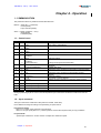
Contents
PAGE
CONTENTS .................................................................................................................................... 5
CHAPTER 1 - GENERAL DESCRIPTION ............................................................................................. 7
1 - INTRODUCTION ...................................................................................................................... 7
2 - ARCHITECTURE OF A POSITIONER........................................................................................... 8
CHAPTER 2 - COMMISSIONING ........................................................................................................ 9
1 – CHECKING THE AMPLIFIER HARDWARE CONFIGURATION ....................................................... 11
2 – PUTTING INTO OPERATION ................................................................................................... 11
3 – MOTOR ADJUSTMENT .......................................................................................................... 11
3.1 – Motor parameter setting ..................................................................................................... 11
3.2 – Current loops (CD1-p)........................................................................................................ 11
3.3 – Adjustment to a new motor ................................................................................................. 12
3.4 - I2t protection ..................................................................................................................... 12
3.5 – Rotation/counting direction.................................................................................................. 13
3.6 – Maximum application speed ................................................................................................ 13
3.7 – Thermal sensor configuration on the CD1-p positioner.............................................................. 13
4 – SERVO CONTROL ADJUSTMENT............................................................................................ 13
4.1 – Regulator parameters ........................................................................................................ 13
4.2 – Regulator adjustment with vertical load.................................................................................. 14
4.3 - Enabling .......................................................................................................................... 14
4.4 – Brake control ................................................................................................................... 14
4.5 – Limit switches adjustment ................................................................................................... 14
5 - CONFIGURATION .................................................................................................................. 15
5.1 – Positioner parameters........................................................................................................ 15
5.2 – Manual motion parameters ................................................................................................. 15
5.3 – Encoder output parameters (SMT-BD1/p only) ........................................................................ 16
6 – PROFIBUS ADDRESS ............................................................................................................ 16
7 – PARAMETERS SAVING.......................................................................................................... 16
8 - PROFIBUS COMMUNICATION ................................................................................................. 17
8.1 - PPO message .................................................................................................................. 17
8.2 - Configuration .................................................................................................................... 19
8.3 – Parameter setting (PKW).................................................................................................... 19
8.4 – Global control................................................................................................................... 20
CHAPTER 3 - PROGRAMMATION.................................................................................................... 21
1 – GENERAL DESCRIPTION ....................................................................................................... 21
2 – EDITION OF A SEQUENCE ..................................................................................................... 21
2.1 – Motion sequence .............................................................................................................. 22
2.2 – Homing sequence ............................................................................................................. 22
2.3 – Speed sequence............................................................................................................... 23
2.4 – Torque sequence (CD1p only) ............................................................................................. 23
2.5 – Sequence control.............................................................................................................. 24
2.6 – Logic outputs ................................................................................................................... 24
CHAPTER 4 - OPERATION ............................................................................................................. 25
1 - COMMUNICATION ................................................................................................................. 25
1.1 – Control word .................................................................................................................... 25
1.2 – Input command ................................................................................................................ 25
1.3 - Status ............................................................................................................................. 26
1.4 - Feedback......................................................................................................................... 26
2 – OPERATION DIAGRAM ................................................................................................................. 27
2.1 – Amplifier control process .................................................................................................... 27
2.2 – Positioning mode .............................................................................................................. 28
3 – DRIVING OF THE POSITIONER ............................................................................................... 29
3.1 – Enabling/disabling............................................................................................................. 29
3.2 – Starting a sequence .......................................................................................................... 29
3.3 – Other movements ............................................................................................................. 29
3.4 – Speed control................................................................................................................... 29
Contents
5
SMT-BD1/p - CD1-p - User manual
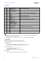
CHAPTER 5 - PARAMETER SETTING BY PROFIBUS ......................................................................... 30
1 – PARAMETER LIST ................................................................................................................. 30
2 – PARAMETERS DESCRIPTION .......................................................................................................... 32
2.1 – Motor parameters.............................................................................................................. 32
2.2 – Current parameters ........................................................................................................... 32
2.3 – Application parameters....................................................................................................... 33
2.4 – Regulator parameters ........................................................................................................ 35
2.5 – Positioner parameters ........................................................................................................ 37
2.6 – Encoder output ................................................................................................................. 38
2.7 – Options ........................................................................................................................... 38
2.8 – Manual motion parameters.................................................................................................. 39
2.9 – Sequence Reading/Writing.................................................................................................. 41
CHAPTER 6 - FAULT FINDING ........................................................................................................ 45
1 - DIAGNOSTICS ....................................................................................................................... 45
1.1 - SMT-BD1/p fault LEDs........................................................................................................ 45
1.2 - CD1-p fault LEDs............................................................................................................... 45
1.3 – Fault reset ....................................................................................................................... 46
2 – FAULT FINDING .................................................................................................................... 46
2.1 – System fault ..................................................................................................................... 46
2.2 – Non stored faults............................................................................................................... 46
2.3 – Stored faults..................................................................................................................... 46
3 – OPERATING PROBLEMS........................................................................................................ 48
3.1 – Motor does not move ......................................................................................................... 48
3.2 – Motor supplied but no torque ............................................................................................... 48
3.3 – Shaft locked, eratic oscillations or rotation at maximum speed .................................................... 48
3.4 – Discontinuous motor rotation with zero torque positions ............................................................ 48
3.5 – Loud crackling noise in the motor at standstill.......................................................................... 48
3.6 – Loud noise in the motor at standstill and when running.............................................................. 48
3.7 – Sequence not executed ...................................................................................................... 48
4 - SERVICE AND MAINTENANCE................................................................................................. 48
APPENDIX.................................................................................................................................... 49
1 – CURRENT LOOPS ADJUSTMENT (SMT-BD1/P ).......................................................................... 49
2 – USE OF THE BD1M PC OSCILLOSCOPE ................................................................................... 50
6
Contents
SMT-BD1/p - CD1-p - User manual
Chapter 1 - General description
1 - INTRODUCTION
INFRANOR® Profibus positioners are digital PWM servo amplifiers that provide motion servo control for AC
sinusoidal motors (brushless) with transmitter resolver.
2 series are available:
-
the plug-in SMT-BD1/p series is available as a single-axis block version or as a multi-axis version that
can receive up to six axes in a standard 19" rack. Both versions are including a power supply unit.
-
the CD1-p series is a small-sized and low current single-axis version.
Both SMT-BD1/p and CD1-p are operating with a PROFIBUS-DP interface; so, driving and parameter setting can
both be entirely made by the bus. The specific software of the INFRANOR ® Profibus positioners, that can be
installed on a laptop, makes the amplifier parameter setting easy, thanks to the serial RS-232 link.
These drives have got the positioner function: 128 positioning movements, homing and speed profile can be
programmed or combined. The control simply consists in selecting one of these movements.
This manual is composed of 6 chapters:
1 - General description
2 - Commissioning
3 - Programmation
4 - Operation
5 - Parameter setting by Profibus
6 - Fault finding
First commissioning of the amplifier
Movement programmation (also called "sequence")
Enabling/disabling and control by Profibus
Parameters list accessible via Profibus
Diagnostics and fault elimination
For the hardware drive installation (dimensions, wiring…) see the various manuals pertaining to each amplifier.
Chapter 1 - General description
7
SMT-BD1/p - CD1-p - User manual
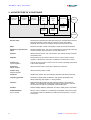
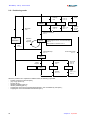
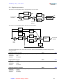
2 - ARCHITECTURE OF A POSITIONER
Profibus-DP
interface
Sequence
switch
Trajectory
generator
Position
loop
Speed
loop
Current loop
Motor
Current
monitor
Position
monitor
Speed
monitor
Resolver
8
Electric motor
Electric device that transforms electrical energy into a mechanical movement.
This transformation is often made by means of current commutation.
Generally, the movement is a rotation but there are also linear motors.
Motor
Electric motor which current commutation is made by mechanical brushes.
Brushless or synchronous
motor
Electric brushless motor. The current commutation is electronically made and
requires a position sensor (resolver, encoder, Hall sensor...).
Resolver
Absolute position sensor over one revolution. The resolver is often used with
a brushless motor.
Amplifier
Electric device for the control of electric motors. It also includes a current
regulator, a speed servo control and, sometimes, a position servo control.
Current loop
Current regulator
Used for the motor current control. The motor torque is generally proportional
to the current amplitude.
Speed loop
Speed regulator
Allows the motor speed control with a speed input command.
Position loop
Position regulator
Allows the motor position control.
Positioner
Amplifier with position loop and trajectory generator that allows positioning.
Trajectory generator
Generates a speed profile (acceleration, step speed, deceleration) that
allows positioning (start position -> arrival position).
Field bus
Digital link that allows real time data exchange between various electric
devices. The characteristic of field busses is their high protection and fault
correction level as well as a predictable communication time.
Profibus
Fieldbus initially defined by Siemens®. This bus is widely used in automation.
Enabled/disabled
(Servo On/Off)
When a motor is enabled, it is controlled by the amplifier and the servo loops
are operating. When it is disabled, its rotation is free and there is no current
in the motor.
Chapter 1 – General description
SMT-BD1/p - CD1-p - User manual
Chapter 2 - Commissioning
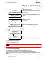
The various stages of a first amplifier commissioning are described below:
Motor adjustment
section 2.3
Servo control adjustment
section 2.4
CONFIGURATION
sections 2.5 and 2.6
PROFIBUS COMMUNICATION
section 2.8
- Current regulator adjustment.
- Definition of the current limitations and of the I 2t protection.
- Adjustment of the motor control parameters.
- Speed limitation definition.
- Rotation direction.
- Adjustment of the servo control parameters according to
the load.
- Definition of the resolution.
- Limit switches.
- Following error.
- Profibus address.
- Start communication between PLC and positioner.
Both operation stages are:
PROGRAMMATION
section 3.1
OPERATION
section 3.2
- Sequences programmation.
- "Operational" phase: sequences execution by Profibus.
The amplifier parameters are accessible via:
- the serial link and the BD1m PC software,
- or by the PKW of the PROFIBUS DP.
CAUTION
Do not make the drive parameter setting by means of both BD1m PC software and Profibus at the same time.
INSTALLATION OF THE PC SOFTWARE
At first, connect the serial RS232 link between PC and amplifier.
The BD1m software is operating with DOS or Windows ® 95/98 in full screen mode.
To install the software, insert the disk in driver A and start the installation programme by entering
A:INSTALL
Enter the communication port (COM1 or COM2) and the selected language and start the installation by clicking on
[INSTALL].
Chapter 2 - Commissioning
9
SMT-BD1/p - CD1-p - User manual
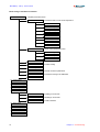
Menu treeing of the BD1m PC software
F2: Parameters
Amplifier parameters menu
F2: Motor
Parameters menu for the motor adjustment
F2: Motor List
F3: Current loop
F4: Auto-phasing
F5: Motor parameters
F6: Phase Lead
F7: Current Limit
F8: Speed Limit
F9: CD1 hardware
F3: Controller
Servo control parameters menu
F2: Auto-tuning
F3: Controller param.
F4: Stability
F4: Encoder
F6: Scale factor
Position scaling
F7: General param.
F8: Manual move.
Manual movement parameters
F9: Save EEPROM
Parameters saving in the EEPROM.
F10: File/Report
F3: Single Move
F4: Sequence Setup
F5: Run Sequence
F6: Profibus
F3: Enable
Enabling in local mode
F4: Disable
Disabling in local mode
F5: Parameter
Profibus address
F7: Reset Error
F8: Oscilloscope
F9: Misc.
F10: Exit
10
Chapter 2 - Commissioning
SMT-BD1/p - CD1-p - User manual
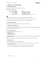
1 – CHECKING THE AMPLIFIER HARDWARE CONFIGURATION
The amplifier standard configuration for MAVILOR motors equipped with a TAMAGAWA resolver is the following:
SMT-BD1/p positioner:
• Resolver adjustment card P RES: 4 x 12,7 KΩ 1%.
• Current loops adjustment.
• Motor thermal probe PTC: Jumper MN.
• Positive control logic: Jumpers E. F. G closed.
• No auxiliary supply: Jumper JK closed and jumper KL open.
• SW1 "OFF" on all switches.
CD1-p positioner:
• Resolver P RES adjustment board: 4 x 12,7 KΩ 1%.
For the amplifier adjustment to other motor or resolver types, or to another control logic, see Installation manual.
2 – PUTTING INTO OPERATION
For the first amplifier powering, see installation manual pertaining to each amplifier type.
The logic voltage (auxiliary supply on the SMT-BD1/p and 24 V on the CD1-p) must be applied to the amplifier
before the power voltage.
CAUTION
When turning off the amplifier, wait for at least 5 seconds before turning power on again.
3 – MOTOR ADJUSTMENT
3.1 – Motor parameter setting
Select the amplifier and fan types required for the motor used.
Select the amplifier current limitation mode. The "Fusing" mode is recommended for the commissioning phases.
In "Fusing" mode, the amplifier is disabled when the current limitation threshold is reached.
In "Limiting" mode, the current is only limited at the value defined by the Rated current parameter when the
limitation threshold is reached.
The parameter Max. current defines the maximum current value supplied by the amplifier. It can vary between 20
% and 100 % of the amplifier current rating. This parameter is defined according to the amplifier and motor
specifications.
The Rated current parameter defines the limitation threshold of the RMS current (I 2t) supplied by the amplifier. It
can vary between 20 % and 50 % of the amplifier current rating. This threshold is set according to the amplifier
and motor specifications.
Check that the values of the Maximum current and Rated current parameters are complying with motor and
amplifier. Otherwise, modify them according to the appropriate motor and amplifier specifications.
The Max. speed parameter defines the maximum motor rotation speed. The speed range is between 100 and
10000 rpm and the resolution is 5 rpm. Check that its value is complying with motor and application. Otherwise,
modify it according to the motor and application specifications.
3.2 – Current loops (CD1-p)
When the motor used is not contained in the motor list, the current loops gain values must be defined
according to the supply voltage (230 V or 400 V), to the amplifier current rating and to the motor inductance.
Chapter 2 - Commissioning
11
SMT-BD1/p - CD1-p - User manual
3.3 – Adjustment to a new motor
Uncouple the motor from the mechanical load and check that the motor shaft is free and for free rotation
(1 revolution) that is not dangerous for the operator.
Execute the auto-phasing procedure (the amplifier must be disabled and the ENABLE signal must be
activated) in order to define the parameters Number of pole pairs, Motor phase and Resolver adjustment.
Please note that during the auto-phasing procedure the motor is automatically enabled and then disabled when
the procedure is over.
If the motor is equipped with a brake, unlock the brake manually before starting the procedure.
The auto-phasing procedure calculates the following parameters:
-
The parameter Number of pole pairs defines the number of motor pole pairs.
The parameter Phases order defines the motor phases order.
The parameter Resolver offset defines the mechanical shift between both motor and resolver
references.
Define the parameter Phase lead from the specific motor parameters (the effects of this parameter are
particularly useful on low inductance motors running at high speeds)
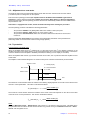
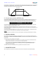
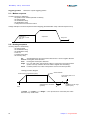
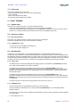
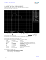
3.4 - I2t protection
Current limitation in Fusing mode
When the amplifier RMS current (I 2t) reaches 85 % of the rated current, the I2t error display is blinking on the
amplifier front panel. If the RMS current (I2t) has not dropped below 85 % of the rated current within 1 second, the
I 2t fault is released and the amplifier is disabled (otherwise, the blinking I2t error display is cancelled).
When the amplifier RMS current (I2t) reaches the rated current value, the I2t protection limits the amplifier current
at this value.
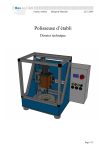
The amplifier current limitation diagram in an extreme case (motor overload or locked shaft) is shown below.
Amplifier current
t1 = blinking display
t2 = Current limitation
Max. current
t3 = I2t fault
Rated current
1 second
time
t0
t1
t2
t3
The maximum current duration before the release of the blinking display depends on the value of the rated current
and max. current parameters. This value is calculated as follows:
Tdyn (second) = t 1 − t0 = 200.
rated current (%)
max. current (%)
The maximum current duration before the limitation at the rated current also depends on the value of the rated
current and max. current parameters. This value is calculated as follows:
Tmax (second) = t 2 - t0 = 240.
rated current (%)
max. current (%)
NOTE
When the Maximum current / Rated current ratio is close to 1, the values of Tdyn and Tmax calculated above
are quite below the real values. But this formula remains very precise as long as the Maximum current / Rated
current ratio is higher than 3/2.
12
Chapter 2 - Commissioning
SMT-BD1/p - CD1-p - User manual
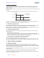
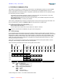
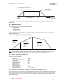
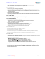
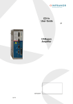
Current limitation in Limiting mode
When the amplifier RMS current (I2t) reaches 85 % of the rated current, the I2t error display is blinking on the
amplifier front panel. When the RMS current (I 2t) drops below 85 % of the rated current, the blinking I 2t error
display is cancelled.
When the amplifier RMS current (I 2t) reaches the rated current value, the I2t protection limits the amplifier current
at this value.
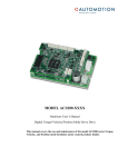
The amplifier current limitation diagram in an extreme case (motor overload or locked shaft) is shown below.
Amplifier current
t1 = blinking display
Max. current
t2 = Current limitation
Rated current
time
t0
t1
t2
The maximum current duration before the release of the blinking display (t1 - t0) and before the rated current
limitation (t2 - t0) is calculated the same way as the Fusing mode (see above).
3.5 – Rotation/counting direction
This possibility defines the position counting direction with regard to the motor rotation direction. For the encoder
position output, the counting direction remains unchanged with regard to the motor rotation direction.
On Mavilor motors, in normal rotation, the position is incrementing in the motor CW rotation direction. In reverse
rotation, the position is incrementing in the motor CCW rotation direction.
3.6 – Maximum application speed
The parameter Max. speed defines the maximum speed with which the amplifier can control the motor. This
parameter must be:
-
lower or equal to the max. motor speed,
approximately 20 % higher than the maximum motor rotation speed in the application. This margin allows a
speed overshooting and avoids a position loop saturation (which would involve a position following error). This
margin can be smaller when the loop bandwidth is high and the accelerations low.
3.7 – Thermal sensor configuration on the CD1-p positioner
There are 2 possible sensor types that can be software configurated:
PTC sensor: the triggering will occur at a value of about 3.3 kOhms of the thermal sensor resistor, that is 140°C.
NTC sensor: the triggering will occur at a value of about 3.3 kOhms of the thermal sensor resistor, that is 140°C.
4 – SERVO CONTROL ADJUSTMENT
4.1 – Regulator parameters
The auto-tuning procedure identifies the motor and load specifications and calculates the regulator gain
parameters. During the procedure, the operator can select 3 bandwidths (Low , Medium and High) and 3 filters
(standard, antiresonance and high stiffness – the last filter is only available for CD1-p). These values correspond
to the cut-off frequency for a 45° speed loop phase shift.
The auto-tuning can be executed with disabled or enabled motor (i.e. vertical load), but the ENABLE signal must
always be activated.
If the motor is equipped with a brake, unlock the brake manually before starting the procedure.
Check for free motor shaft rotation over one revolution, that is not dangerous for operator and machine before
starting the auto-tuning with filter = standard.
Chapter 2 - Commissioning
13
SMT-BD1/p - CD1-p - User manual
After the auto-tuning procedure, check that the motor correctly runs in both directions.
Check the response for a small movement without IDC saturation.
In case of loud noise in the motor at standstill and when running, check the rigidity of the transmission between
motor and load (backlashes and elasticities in gears and couplings).
If necessary, renew the auto-tuning procedure by selecting a lower bandwidth. If the problem remains, renew the
auto-tuning procedure by activating the antiresonance filter.
Adjust more accurately the loop response stability by adjusting the stability gain.
4.2 – Regulator adjustment with vertical load
In the case of an axis with unbalanced load (constant torque due to a vertical load), proceed as follows:
Select the current "Limiting" mode.
Select the regulator type (PI or PI2).
Initialize the speed loop gains corresponding to the unloaded motor (run the auto-tuning procedure with the motor
uncoupled from its mechanical load).
Couple the motor with the load. If possible, make a speed control; otherwise, close the position loop with a stable
gain.
Move the shaft by means of the speed input command until a maintaining position where one motor revolution is
not dangerous for operator and machine (far enough from the mechanical limit stops).
Run the auto-tuning function with motor at standstill. If the motor shaft is moving, the auto-tuning has not been
accepted by the amplifier.
4.3 - Enabling
The enabling can be made:
- by Profibus (see operation diagram for the enabling procedure) or
- by the BD1m PC software, in local mode.
4.4 – Brake control
•
The SMT-BD1/p amplifier is equipped with a brake control signal.
This brake control signal is low powered and cannot directly control the brake. The BMM 05 AF single-axis
rack is therefore equipped with a power relay that allows the brake control (the multiaxes rack is not equipped
with this relay).
•
The CD1-p amplifier has got a brake control (made by transistor).
•
The brake control is activated (relay open) or disabled (relay closed) according to the amplifier status (disabled
or enabled).
4.5 – Limit switches adjustment
The limit switch inputs are inputs for a proximity sensor that stops the motor with maximum deceleration. When
both limit switches are correctly placed on the motor stroke, they are a protection for the machine in case of
incorrect movement.
The limit switches are only defined according to the physical motor rotation. They are not depending on the
selected "rotation/counting direction".
On Mavilor motors, if the option "rotation/counting direction" is normal, the FC+ input must be wired in the positive
motor counting direction.
For checking the limit switches:
- move the motor in one direction,
- activate the limit switch which is located in the movement direction (artificially, if necessary),
14
Chapter 2 - Commissioning
SMT-BD1/p - CD1-p - User manual
- check that the motor is stopping,
- if the motor does not stop, the limit switches are reversed wired.
Check also in the opposite direction.
Notes
-
The motor is stopped with maximum deceleration by a limit switch.
Recall: The limit switches are wired as "normally closed".
5 - CONFIGURATION
5.1 – Positioner parameters
Position resolution: defines the position resolution for one motor revolution according to the number of decimals
and the unit required. The adjustment range is between 16 and 65536 ppr.
Following error: defines the following error triggering threshold.
It is important to correctly adjust this value in order to get a good protection.
It can be adjusted like follows:
1 - Make the motor rotating with the desired operation cycles and measure the maximum following error
threshold:
- either by means of the BD1m PC software oscilloscope,
- or by reducing the following error threshold value until the fault is triggered,
2 - Then set the following error threshold at this value plus a margin of 30 to 50 %.
Example: Adjustment of the following error threshold on an axis with:
Position resolution = 5000.
Maximum following error measured by oscilloscope = 0,05 V.
The following error value is: 0,05 / 10 x 32767 = 164.
The threshold is set at 246 (margin = 50 %).
Note: In the BD1m PC software, if the number of decimals is set at 3, the value that must be entered is 0,246.
Speed profile: trapezoidal or S-curve.
Brake delay active: defines the time between the brake enabling and the amplifier disabling.
- brake activation (relay open),
- delay time,
- amplifier disabling.
Brake delay inactive: defines the time between the amplifier enabling and the brake disabling:
- amplifier enabling,
- delay time,
- brake disabling (relay closed).
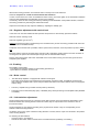
5.2 – Manual motion parameters
There are 2 types of manual motion:
- basic positioning: moving of the motor until a given position directly by the operator.
- jog: continuous movement when the jog signal is activated (JOG+ for a movement in the positive
direction and JOG- for a movement in the negative direction).
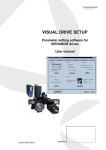
The motion profile parameters are:
- "motion speed",
- "acceleration time",
- "deceleration time"
Chapter 2 - Commissioning
15
SMT-BD1/p - CD1-p - User manual
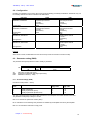
The parameters "acceleration time" and "deceleration time" define the time with regard to the max. speed (defined
by the parameter "Speed limitation"). When the motion speed is lower than the maximum speed, the trajectory
acceleration and deceleration times are proportionally smaller.
Max. speed
Motion speed
parameter
Acceleration ramp
Deceleration ramp
5.3 – Encoder output parameters (SMT-BD1/p only)
The parameter Encoder resolution defines the encoder resolution on channels A and B (X2 connector) of the
encoder position output for one motor shaft revolution. Binary and decimal values are both accepted. The
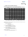
maximum encoder resolution per revolution is limited by the motor rotation speed as shown in the table below.
Max. possible speed (rpm)
Max. encoder resolution
900
8192
3600
4096
10000
1024
The parameter Number of zero pulse defines the number of marker pulses on channel Z for one motor shaft
revolution. The adjustment range is between 1 and 16.
The parameter Zero pulse origin shift defines the shift between the first marker pulse on channel Z and the
resolver reference position. The adjustment range is between 0 and 32 767. The value 32 767 corresponds to one
motor shaft revolution.
The parameter Zero pulse width defines the marker pulses width on channel Z in ppr. The adjustment range is
between 8 and 32 767. The value 32 767 corresponds to one motor shaft revolution.
Caution
The encoder output is not available on the CD1-p series amplifiers, eventhough these parameters are existing.
6 – PROFIBUS ADDRESS
Each amplifier of the network is identified by one single address (1 to 125). The positioner is delivered with the
default address 126 which is not an operational address. This address must be modified before putting the bus
into operation.
The SMT-BD1/p or CD1-p address can be modified:
- by the serial RS-232 link (BD1m PC software). The new address must be saved in the EEPROM and the
amplifier must be switched on in order to get the new address operational;
- or by a Profibus class 2 master device. The address modification is only possible when the bus is not
running. In this case, the address will be automatically saved in the amplifier EEPROM and will be
operational at the bus starting.
The identity number of the SMT-BD1/p and CD1-p positioners under Profibus is 0x00C7.
7 – PARAMETERS SAVING
When all adjustments are made, the parameters must be saved in the EEPROM ( with disabled amplifier).
16
Chapter 2 - Commissioning
SMT-BD1/p - CD1-p - User manual
8 - PROFIBUS COMMUNICATION
The Profibus communication is a master-slave communication. The INFRANOR ® positioner is a slave amplifier
and the only important parameter to be defined for the communication is the amplifier address on the bus.
All other parameters (communication speed, configuration, parameters) are defined in the PLC (master) and will
be automatically sent to the positioner:
- the available communication speeds are: 9,6 KB, 19,2 KB, 93,72 KB, 187,5 KB, 500 KB, 1,5 KB, 3 KB,
6 KB, 12 KB and will be automatically detected by the positioner.
- the configuration used will be sent to the slave at the bus starting. The available configurations are PPO1,
PPO2, PPO3 or PPO4,
- default parameter setting: not used by the positioner.
These various possibilities are pre-defined in a GSD file proper to each product range running with Profibus. The
file for the INFRANOR® positioner is INFR00C7.GSD and is provided by the PC-BD1m disk.
When defining the network on the master, please:
- import the slave GSD file if this has not yet been done,
- create a network with the master,
- connect a slave on the network with the same address as defined in the slave.
Note: When the communication is established, the green "RUN" LED lights up.
8.1 - PPO message
In the PROFIBUS-DP communication model, a slave module consists of a certain number of inputs-outputs or
inputs-outputs modules. Each module is defined by an identifier. This identifier contains information on the module
direction (input, output or input-output), on the number of bytes or words and on the module consistancy. The
configuration is defined in the DP master and is sent to the slave by means of the Chk_Cfg functions at the bus
starting. The slave checks if this configuration is compatible and configures itself before switching on to data
exchange mode (Data_Exchange).
There is also a communication mechanism more complicated than a basic inputs/outputs identifier: the PPO
messages. These messages are often used in the "device profiles".
There are 5 PPO types defined for the various device profiles under Profibus:
PKW
PZD
PKE
IND
PWE
1st
Word
2nd
Word
3rd
Word
4th
Word
PZD1
STW
ZSW
PZD2
HSW
HIW
PZD
3
PZD
4
PZD
5
PZD
6
PZD
7
PZD
8
PZD
9
PZD
10
1st
Word
2nd
Word
3rd
Word
4th
Word
5th
Word
6th
Word
7th
Word
8th
Word
9th
Word
10th
Word
PPO1
PPO2
PPO3
PPO4
PPO5
PKW
PZD
Parameter setting data.
PKE
Parameter code (bytes 1 to 2).
IND
Home position (byte 3).
PWE
Parameter value (bytes 5 to 8).
Process data (cyclically transferred).
STW
Control.
ZSW
Status.
HSW
Input command.
HIW
Information feedback.
A PPO message can contain 1 or 2 modules called PKW and PZD.
Chapter 2 - Commissioning
17
SMT-BD1/p - CD1-p - User manual
Each module (PKW or PZD) is defined as input-output and is consistant over the whole module length.
The communication is made by the reading or writing of PPO messages (the PKW and PZD modules are input
and output at the same time). The master sends a message by a PPO-write and receives a message by PPOread. The PPO-write and PPO-read messages are cyclically transferred by the PROFIBUS DP Data_Exchange
function.
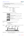
The modules are consistant. This means that the different words of a same message must be transmitted or
received in one single transfer. So, it is not possible to directly read or write in the PLC inputs/outputs area;
special functions must be used for the data reading or writing.
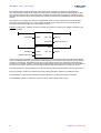
Example: In the STEP7 ® software, the SFC14 and SFC15 functions are used for the reading and writing of the
consistant modules.
EN
W#16#108
LADDR
EN
W#16#108
P#M 20.0 BYTE 12
SFC14
RET_VAL
MW100
RECORD
P#M 40.0 BYTE 12
SFC15
LADDR
ENO
ENO
RET_VAL
MW101
RECORD
In the above example, the SFC14 and SFC15 functions are used for reading or writing the PZD module (PPO2
case). The W#16#108 address is the physical module address on the network that is obtained when connecting
the slave to the network. This address is the same for the reading (SFC14) and writing (SFC15) because the
module is an input-output module. The result of the reading will be transferred in the memory area at the address
40 by SFC14 (12 bytes). The SFC15 function will transfer the data at the address 20 (12 bytes) on the bus.
The PKW will require a SFC14 (reading) and a SFC15 (writing) and the PZD will require a SFC14 and a SFC15.
PKW is by definition used for the positioner parameter setting and PZD is used for its operational control.
The INFRANOR® positioner uses the PPO messages mechanism for communicating by Profibus-DP.
The SMT-BD1/p and CD1-p positioners accept the PPO1, PPO2, PPO3 or PPO4 types.
18
Chapter 2 - Commissioning
SMT-BD1/p - CD1-p - User manual
8.2 - Configuration
Normally, the identifiers of the various PPO types are automatically provided by the GSD file. Otherwise, they can
be manually defined with values indicated in the table below:
PPO type
Type 1
ReadPPO1, WritePPO1
Configuration
Type 2
ReadPPO2, WritePPO2
Configuration
Type 3
ReadPPO3, WritePPO3
PKW
PKW (4 words)
Inputs/outputs module
4 words
Consistency
0xF3
PKW (4 words)
Inputs/outputs module
4 words
Consistency
0xF3
PZD
PZD
Inputs/outputs module
2 words
Consistency
0xF1
PZD
Inputs/outputs module
6 words
Consistency
0xF5
PZD
Inputs/outputs module
2 words
Consistency
0xF1
PZD
Inputs/outputs module
6 words
Consistency
0xF5
Configuration
Type 4
ReadPPO4, Write PPO4
Configuration
Example
When PPO2 is used, the identifiers are 0xF3 and 0xF5 (4 words for PKW and 6 words for PZD).
8.3 – Parameter setting (PKW)
The parameter area (PKW) allows to read or modify a parameter.
Parameter identifier (PKE)
Bit : 15
12
11
AK
SPM
AK:
SPM:
PNU:
10
0
PNU
Instruction or reply code (0-15)
Toggle bit for parameter data signal processing.
Parameter number (1..1999)
8.3.1 - Instruction/Reply (PKW)
Instructions code (master -> slave):
Instruction
Code
0
1
2
3
Function
No instruction
Read a parameter
Modify a parameter (word)
Modify a parameter (double word)
Positive
reply code
0
1
1
2
Negative
reply code
7/8
7/8
7/8
The reply code mentioned in the above table includes the normal replies associated with the instructions.
The parameter code (PKE) is always of 16 bits.
Bits 0 to 10 include the parameter number (PNU).
Bit 11 indicates an event message: the parameter is modified by the amplifier and sent by the amplifier.
Bits 12 to 15 include the instruction or reply code.
Chapter 2 - Commissioning
19
SMT-BD1/p - CD1-p - User manual
Reply codes (slave -> master):
Reply code
0
1
2
7
8
Function
No function.
Value of the transferred parameter (word).
Value of the transferred parameter (double word).
Instruction cannot be executed (see error code).
PKW interface inhibited.
For instructions that cannot be executed, the slave answers with an error number in the 4 th word of the PKW (bits
7 and 8).
Error number
0
1
2
3
5
17
18
Description
PNU unlegal.
Parameter cannot be changed.
Exceeding of lower or upper limit.
Home position error.
Incorrect data type
Instruction cannot be executed during operation.
Other error
8.3.2 – Parameter value (PWE)
PWE includes the data for the parameter to be transferred:
- word: bytes 7 (MSB) and 8 (LSB).
- double word: bytes 5 (MSB) to 8 (LSB).
8.3.3 – Rule of the instruction/reply communication
- The master sends an instruction to the slave with the message "PPO write". It repeats this instruction until it
gets a reply from the slave by "PPO read". This procedure guarantees the instruction/reply communication by
the operator.
- Just one single instruction can be executed at once.
- A slave provides the reply until the master sends a new instruction.
- An instruction (8 bytes) must be completely transferred in a message, and a reply as well.
- If no parameter setting information is required, the master must send 0 in AK (no instruction).
8.4 – Global control
The PROFIBUS DP global control mechanism can be used for synchronizing the outputs and inputs of several
modules and several slaves. There are 4 global controls: SYNC, UNSYNC, FREEZE and UNFREEZE.
When the master sends a global SYNC control, the outputs of the addressed slave are frozen at their present
values. When the master sends the next data, those are stored in the slave and the outputs status remains
unchanged. When the next SYNC control is sent, the stored outputs values are switched through to the outputs.
An UNSYNC control can be used for ending the synchronous mode.
The FREEZE control also allows the slave to froze the inputs at their present values and to send them with the
next data transfers. The inputs are not updated until the next FREEZE control. The FREEZE mode can be left by
means of an UNFREEZE control.
The SMT-BD1/p and CD1-p positioners accept the global controls SYNC, UNSYNC, FREEZE and UNFREEZE.
20
Chapter 2 - Commissioning
SMT-BD1/p - CD1-p - User manual
Chapter 3 - Programmation
1 – GENERAL DESCRIPTION
Both SMT-BD1/p and CD1-p amplifiers can have up to 128 pre-programmed sequences. Each sequence can be
either:
- an absolute motion or
- a relative motion or
- a homing or
- a speed profile or
- a torque sequence (speed profile with current limitation).
The sequences can be automatically linked up: when a sequence is over, it can directly execute another
sequence.
The SMT-BD1/p and CD1-p positioners have got 8 programmable and virtual logic outputs (triggering at the
sequences execution) and 8 virtual logic inputs allowing to control a sequence start or stopping (the virtual logic
inputs and outputs are only visible on the bus and have no physical existence).
The programmation consists in initializing the sequences with the desired values.
2 – EDITION OF A SEQUENCE
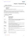
Parameters of a sequence:
Type
Defines the motion type.
ABS: absolute positioning.
REL: relative positioning.
HOME: axis homing.
SPEED: speed profile.
Position
Position to be reached in absolute or relative mode according to above mentioned
parameter. If the motion type is a homing procedure, Position then indicates the value
to be loaded in the position counter at the home position found.
Speed
Defines the motion speed in rpm.
Acceleration
Defines the acceleration ramp in ms.
Deceleration
Defines the deceleration ramp in ms. This parameter can be equal to 0 if a sequences
linkage can be made without stopping the motor.
See also section 3.9 "Manual motion parameters" for the definition of the parameters
"motion speed", "acceleration time" and "deceleration time".
Delay Time
orTimeOut
Defines, in ms, the delay time at the end of the positioning.
If the motion is a homing procedure, this parameter defines, in seconds, the "time out",
that is the time after which the amplifier releases an error (if it does not find the home
position). When this value is 0, the "time out" protection is not activated.
Link
Defines the sequence to be executed after the present one.
Counter
Defines how many times the sequence must be executed. This counter is decremented
each time a sequence is over.
Counter link
Defines the number of the sequence to be executed when the counter (see above) is not
at 0.
Logic outputs
Defines the possible effect on the outputs.
Triggering
Defines the outputs triggering moment.
Chapter 3 - Programmation
21
SMT-BD1/p - CD1-p - User manual
Triggering position
Defines the outputs triggering position
2.1 – Motion sequence
A motion sequence is defined by:
- the position to be reached (absolute or relative),
- the motion speed,
- the acceleration ramp,
- the deceleration ramp,
- a delay time at the end of the motion.
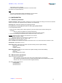
Linkage example of 2 motion sequences without stopping (the deceleration ramp of the first sequence is 0):
sequence 1
with Tdec = 0 and
link = 2
sequence 2
delay time
2.2 – Homing sequence
A homing sequence is defined by:
- the motion speed,
- the acceleration ramp,
- the deceleration ramp,
- a time out,
- a position reset value,
- the control (5 bits):
Dir
Switch
Zero
0rigin
Reset
Searching direction: 0 for the positive direction and 1 for the negative direction.
Homing with switch detection.
Homing with marker pulse detection.
In a case with switch, this parameter allows to come back to the home position
(motion reversal); otherwise the motor will be stopped after the braking.
Load the position reset value in the position counter at the home position.
Homing procedure diagram:
Switch search (programmed speed)
Switch detection
First marker pulse out of
the switch
Start
Withdrawal from the switch
(speed/4)
Positioning on the origin
(marker pulse)
If Switch = 1 and Zero = 1 or Origin = 1, the speed can be reversed by the switch
detection or by a limit switch.
22
Chapter 3 - Programmation
SMT-BD1/p - CD1-p - User manual
Procedure diagram with switch:
Switch detection
(home position)
Switch search (programmed speed)
Load the position counter
with the Pos value
Start
Return to home
position (speed/4)
When sequence 0 contains a homing procedure, no other sequence can be executed, at power on, before
sequence 0.
2.3 – Speed sequence
The speed sequences are defined by these parameters:
- motion speed
- motion time
- acceleration time
- deceleration time.
When the motion time exceeds 16000 ms, this means an infinite motion ! (the stop condition can be used for
stopping the sequence).
The sequences linkage allows to create speed profiles.
Sequence 1
Speed = 1500
Tacc = 2000
Time = 0
Tdec = 0
Link = 2
Sequence 2
Speed = 3000
Tacc = 3000
Time = 0
Tdec = 0
Link = 3
Sequence 3
Speed = 2000
Tacc = 3000
Time = 0
Tdec = 1500
Link = -1
Note: The parameters "acceleration" and "deceleration" are real acceleration and deceleration times and not
acceleration and deceleration ramps as they are in a positioning sequence or a homing sequence.
2.4 – Torque sequence (CD1p only)
Torque sequence parameters:
Motion type
Torque input command (%)
Speed (rpm)
Acceleration (ms)
Deceleration (ms)
Delay time (ms)
Next sequence
Outputs (87654321)
Outputs triggering
Start condition (8..1)
: Torque
: 40.0
: 500
: 400
: 400
: 120
:
: .......1
: Hold
: 1....... [X] Stop
The "Acceleration" and "Deceleration" parameters are acceleration and deceleration times.
In a torque sequence, the motor runs at constant speed until it is locked. The current then raises up to the value
defined in percentage of the max. current value defined by the Max. current parameter. When the motor has got
a zero speed and the current is reached, the positioner is holding at this current during the time defined by the
Delay time parameter.
Chapter 3 - Programmation
23
SMT-BD1/p - CD1-p - User manual
If the "time delay" exceeds 16000, the torque holding is infinite. The torque sequence can be left either by:
- the START signal that starts another sequence or by
- the signal of a stop condition.
The triggering of the « HOLD » outputs allows the outputs activation when the motor speed is zero and the current
is reached.
2.5 – Sequence control
The sequences linkage is controlled by the parameters "Link", "Counter" and "Counter link".
Example:
Sequence 1:
Link = 2
Counter = -1
Counter link = -1
Sequence 2:
Link = 3
Counter = 2
Counter link = 1
Sequence 3:
Link = -1
Counter = -1
Counter link = -1
If the execution starts at sequence 1, the programme will be the following:
Sequence 1
Start of sequence nr. 1, then link (parameter "Link") to sequence
nr. 2.
Sequence 2
First execution of sequence nr. 2, then connection to sequence
nr. 1 (parameter "Counter link").
Sequence 1
Execution of sequence nr. 1, then connection to sequence nr. 2
(parameter "Link").
Sequence 2
Second execution of sequence nr. 2, then connection to sequence
nr. 3 (parameter "Link").
Sequence 3
Execute sequence nr. 3, then end the programme.
2.6 – Logic outputs
Outputs
Triggering
The action on the 8 logic outputs can be defined as follows:
- do not modify the output status,
- set the output at 1,
- set the output at 0,
- reverse the output (toggle).
The outputs triggering moment can be defined, during a motion, the 5 different ways described
below:
BEGIN: logic
output at
sequence
beginning
SPEED: logic
output when
speed is
reached
POS: logic
output when the
motor passes a
position
HOLD: logic
output when
reaching the
position (end of
trajectory)
END: logic
output at
sequence end
In a homing sequence, the outputs trigger only at the end of the sequence.
In a speed sequence, the "HOLD" and "POS" triggering is not possible.
Triggering position:
24
Defines the position where the logic output must be triggered when it is programmed in
"POS" triggering (see Triggering above).
Chapter 3 - Programmation
SMT-BD1/p - CD1-p - User manual
Chapter 4 - Operation
1 - COMMUNICATION
The positioner is driven by Profibus with the PZD data area.
Master -> slave (PLC -> positioner):
- Control (STW)
- Input command (HSW)
Slave -> master (positioner -> PLC):
- Status (ZSW)
- Feedback (HIW)
1.1 – Control word
Bit
0
3
4
Value
1
0
1
0
1
0
1
1
5
0
1
6
0
↑↓
1
2
7
Meaning
ON
OFF1
Operational condition
OFF2
Operational condition
OFF3
Operation enabled
Operational condition for the
positioner
Stop
Operational condition for the
positioner
Intermediate stop
Execute positioner function
Maximum braking.
Must be set at 1 for a sequence execution.
Jog +
Continuous motor movement in the positive counting direction.
Jog -
Continuous motor movement in the negative counting
direction.
Control by profibus
Local mode control by RS-232
Release a homing procedure on the rising edge of this bit.
11
12
↑↓
Absolute positioning
13
↑↓
Relative positioning
10
A sequence can be executed on a 6 bit edge.
Fault acknowledgment
Command
Local
Homing
9
Emergency stop: maximum deceleration.
Braking with programmed deceleration.
Each edge on this bit releases the execution of the selected
sequence.
Amplifier fault reset.
↑
1
0
1
0
1
0
↑↓
8
Notes
Enabling.
Stop, braking and disabling.
Amplifier ready.
14
15
During a positioning by bit 12 or bit 13, the 32 bit position input command is contained in words 5 and 6 of the
PZD.
1.2 – Input command
The input command is contained in HIW (2nd word of PZD - PPO write).
It has different meanings according to the positioning or speed control.
In positioning mode:
Bits 0 to 7: number of the sequence to be executed.
Bits 8 to 15: logic inputs (bits 0 to 7). These inputs are used for the sequence start (or stop) conditions.
In speed mode:
Speed input command on 16 bits: 0x7FFF corresponds to maximum speed.
Chapter 4 – Operation
25
SMT-BD1/p - CD1-p - User manual
1.3 - Status
Bit
0
1
2
3
4
5
6
7
8
9
10
11
12
13
14
15
Value
1
0
1
0
1
0
1
0
1
0
1
0
1
0
1
0
1
0
1
0
1
0
1
0
↑↓
1
0
1
0
1
0
Meaning
Ready for enabling
Not ready
Ready for operation
Notes
Ready for enabling (ENABLE).
Operation enabled
Error
No OFF2
OFF2
No OFF3
OFF3
Enabling inhibited
Enabling
Warning
Amplifier fault after error reset; is in "disabled" status.
Instruction "OFF2" available
Instruction "OFF3" available
Warning signal; the amplifier goes on operating.
No following error
Following error
Operation via Profibus
Operation in local mode
Position is reached
Home position found
Input command
acknowledgment
Acknowledgment of a sequence triggering
Motor stopped
Sequence running
Speed is reached
Notes
-
When the motor reaches a limit switch, the following error is activated (bit 8) and the amplifier fault is not
activated (bit 3). The motor remains enabled.
-
When switching from the "Profibus" mode to local mode or vice versa, the amplifier is disabled.
1.4 - Feedback
The feedback is included in HIW (2nd word of PZD - PPO read).
It has got different meanings according to positioning or speed control.
In positioning mode:
Bits 0 to 7 of the HIW: number of the running sequence (otherwise 0xFF).
Bits 8 to 15 of the HIW: programmable logic outputs (0 to 7).
If PPO2 or PPO4 are used:
PZD3 contains the current monitor in the motor.
PZD4 contains the motor speed.
PZD5 (MSB) and PSD6 (LSB) contain the motor position.
In speed mode:
Motor speed (0x7FFF corresponds to the maximum motor speed).
26
Chapter 4 - Operation
SMT-BD1/p - CD1-p - User manual
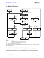
2 – Operation diagram
2.1 – Amplifier control process
Power
ON
ENABLE
inhibited
S.6 = 1
OFF1
control = xxxx x1xx xxxx xxx0
ENABLE
not ready
C.3 = 0
S.2 = 0
Operation
inhibition
control
xxxx x1xx xxxx x110
Ready for
ENABLE
Operation inhibited
Deceleration
OFF1 active
phase 1
S.0 = 1
S.3 = 1
S.1 = 1
Enabling
C.3 = 1
Fast brake
S.5 = 0
OFF3
C.2 = 0
OFF3 Active
phase 1
OFF2
C.1 = 0
OFF2 active
S.4 = 0
Motor
stop
OFF1 active
phase 2
OFF3 active
phase 2
Disabled
disabled
Operation
enabled
Notes:
ENABLE
C.n
S.n
Error
Error reset
C.7 = 1
Motor
stop
S.1 = 0
Error
ON
C.0 = 1
Ready
OFF1
C.0 = 0
S.6 = 1
S.9 = 1
disabled
S.2 = 1
Enabling.
Indicates bit n of the control word (see section 2.2).
Indicates bit n of the status word (see section 2.2).
This diagram describes the amplifier behaviour:
The enabling process includes 5 stages: "ENABLE inhibited", "ENABLE not ready", "Ready for ENABLE", "Ready"
and "Operation enabled".
The 3 OFF1, OFF2 and OFF3 functions allow various ways to disable the motor.
The functions "Error" and "OFF" are effective at each level of the diagram. "OFF3" is a stop with maximum
deceleration. "OFF2" has a priority over "OFF1" which has a priority over "OFF3".
Contrarily to the parameter setting, there is no direct acknowledgment for each control word bit. The positioner
status must be checked in order to make sure that the command could be executed.
Chapter 4 – Operation
27
SMT-BD1/p - CD1-p - User manual
2.2 – Positioning mode
Operation
enabled
Homing
JOG
Indexing
C.11 = 1
Drive task
over
End of
move
JOG end
C.8 = 0
C.9 = 0
Indexing
over
Manual
move
JOG
C.8 = 1 or
C.9 = 1
Edge on
C.12 or
C.13
Positioner activation
C.4 = 1
Brake with
max.
deceleration
Execution
of a new
sequence
Positioner
function
Execution of a sequence
Acknowledgment of the command with edge
on S.12
When position is reached, S.10 = 1
Stop
C.4 = 0
Intermediate stop
C.5 = 0
Continue drive task
C.5 = 1
Brake with
ramp
Motor
stopped
S.13 = 1
Intermediate
stop
End JOG
C.8 = 0
C.9 = 0
Homing
over
Homing
JOG
Homing
C.11 = 1
JOG
C.8 = 1 or
C.9 = 1
When the positioner is in "Operation enabled" status, the following is possible:
- starting a sequence execution (bit 6),
- jog+ or jog- (bit 8 or 9),
- homing (bit 11),
- absolute positioning (bit 12),
- relative positioning (bit 13),
- stopping the motor with a programmed deceleration – the one defined by JOG (bit 5) -,
- stopping the motor with maximum deceleration (bit 4).
28
Chapter 4 - Operation
SMT-BD1/p - CD1-p - User manual
3 – DRIVING OF THE POSITIONER
3.1 – Enabling/disabling
The enabling procedure is defined in the diagram of section 2.1
Example of a simplified enabling:
Stages
1
2
3
4
5
Communication
PLC -> Positioner
PLC -> Positioner
PLC -> Positioner
PLC -> Positioner
Positioner -> PLC
Value
Send control word = 0400h
Send control word = 0406h
Send control word = 0407h
Send control word = 043Fh
Check status word = xxxx xx11 xx11 0111b
Notes
-
The positioner bus cycle time is 1 ms; check for at least 1 ms between 2 commands.
-
In the above procedure, the positioner status is not checked at each stages but only at the end.
The disabling can be simply made by disabling one of the OFF1 or OFF2 or OFF3 bits.
3.2 – Starting a sequence
When the positioner is in "Operation enabled" status, a sequence is started by:
-
entering the sequence number in PZD 2,
reversing bit 6 of the control word.
If a new sequence is started whereas the positioner is executing a sequence, the positioner immediately executes
the new sequence without stopping the motor.
3.3 – Other movements
The other possible non programmed movements are:
- jog+ or Jog- (bit 8 or 9),
- homing (bit 11),
- absolute positioning (bit 12),
- relative positioning (bit 13).
The movements are mutually exclusive (including a sequence execution): when a movement is running, no other
movement is possible.
For absolute or relative positionings, the 32 bit position input command is contained in PZD5 and PZD6.
3.4 – Speed control
It is also possible to control the positioner in speed mode:
-
switch to speed mode by means of parameter PNU 720, with disabled motor. At power on, the amplifier is
always in positioning mode.
-
the PLC must send the speed input command in PZD2 (16 bits full scale) of the PPO-write.
-
the PLC can read the motor speed monitor in PZD2 (16 bits full scale) of the PPO-read.
Chapter 4 – Operation
29
SMT-BD1/p - CD1-p - User manual
Chapter 5 - Parameter setting by Profibus
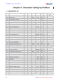
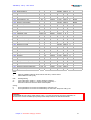
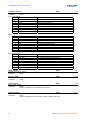
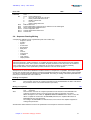
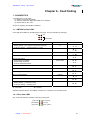
1 – PARAMETER LIST
PNU
Parameter
700
701
702
703
704
Number of motor pole pairs
Motor phases order
Resolver shift
Phase lead
Auto-phasing procedure
710
711
712
713
Max. current
Rated current
I 2t protection mode
Current limitation
715+
716+
717+
718+
719+
720
721
722
723
Current / Voltage rating
Kp gain of D current loop
Ki gain of D current loop
Kp gain of Q current loop
Ki gain of Q current loop
Amplifier mode
Max. motor speed
Motor rotation direction
Acceleration ramp
725+
726
727
728
729
Motor thermal sensor configuration
Brake control active delay
Brake control inactive delay
Manual brake control
Saving in an EEPROM
730
731
732
733
734
735
736
737+
738+
739+
740
741
742
743
744*
745*
746*
747*
748*
Proportional speed loop gain
Integral speed loop gain
Proportional position loop gain
Feedforward Speed 1 Gain
Current control filter
Anti-resonance filter
Auto-tuning procedure
Feedforward Acceleration gain
Feedforward Speed 2 Gain
Damping Speed Gain
Position resolution
Following error threshold
Positioner configuration
User Output
Dead band
Position modulo
Position reset
Negative software limit switch
Positive software limit switch
750
751
752
753
754
Encoder output resolution
Number of marker pulses
Marker pulse shift
Marker pulse width
Encoder output programmation
756*
757*
SEQ pulse duration
“INPOS” window
30
Unit
Min.
Max.
1
12
0
65535
%
%
6553
6553
32767
16384
%
0
32767
1
0
1
0
65535
65535
65535
65535
rpm
100
10000
ms
0
16000
ms
ms
0
0
16000
16000
0
0
0
0
2832
0
0
0
0
0
16
1
65535
65535
65535
65535
61545
1
5
65535
65535
65535
65534
32767
ppr
pulse
ms
Size
R/W Saving
Default
value
word
word
word
word
R/W
R/W
R/W
R/W
W
E
E
E
E
4
0xAAAA
0
0
word
word
Boolean
word
R/W
R/W
R/W
R/W
E
E
E
0x7FFF
0x4000
1
0x7FFF
word
word
word
word
word
word
word
Boolean
word
R
R/W
R/W
R/W
R/W
R/W
R/W
R/W
R/W
E
E
E
E
0x100
0
0x100
0
E
E
E
3000
0
1
Boolean
word
word
Boolean
-
R/W
R/W
R/W
W
W
E
E
E
0
0
word
word
word
word
word
Boolean
word
word
word
word
Word
Word
Word
Word
Word
double
double
double
double
R/W
R/W
R/W
R/W
R/W
R/W
W
R/W
R/W
R/W
R/W
R/W
R/W
R/W
R/W
R/W
R/W
R/W
R/W
E
E
E
E
E
E
0x64
0
0
0
0x3000
0
E
E
E
E
E
E
E
E
E
E
E
0
0
0
0x1388
0x7FFF
0
0
0
0
0
0x7FFFFFFF
0x80000000
16
1
0
0
8192
16
32767
32767
word
word
word
word
-
R/W
R/W
R/W
R/W
W
E
E
E
E
0x400
1
0
0x10
0
16383
word
double
R/W
R/W
E
E
0
0
Chapter 5 - Parameter setting by Profibus
SMT-BD1/p - CD1-p - User manual
758*
759*
760
761
762
763
764
765
766
767
CAM Position 1
CAM Position 2
Manual move speed
Manual mode acceleration
Manual mode deceleration
Speed in jog
Acceleration in jog
Deceleration in jog
Homing configuration
Position input command
double
double
word
word
word
word
word
word
16 bits
double
R/W
R/W
R/W
R/W
R/W
R/W
R/W
R/W
R/W
R/W
770
771
773
774
775
776
777
778+
Positioner software version
Profibus software version
Amplifier error
Motor position
Resolver value
Motor speed
Motor current
Error code (CD1-p)
double
word
double
double
Word
integer
Integer
word
R
R
R
R
R
R
R
R
780
781
782
783
784
785
786
787
788
789
790
791
792
793
Sequence reading
Sequence writing
Sequence control
Position
Speed
Acceleration
Deceleration
Delay time
Link
Counter
Counter link
Condition inputs
Programmable logic outputs
Triggering position
B
word
word
16 bits
double
word
word
word
word
word
word
word
16 bits
16 bits
double
W
W
R/W
R/W
R/W
R/W
R/W
R/W
R/W
R/W
R/W
R/W
R/W
R/W
pulse
rpm
ms
ms
ms
A
0
1
0
0
-1
0
-1
B
10000
16000
16000
16767
127
16000
127
pulse
A
796
797
807
Sequence position modification
Sequence speed modification
Sequence torque modification
pulse
rpm
%
A
0
0
B
10000
32767
double
word
word
R/W
R/W
R/W
rpm
ms
ms
rpm
ms
ms
1
1
1
1
1
1
10000
16000
16000
10000
16000
16000
pulse
A
B
pulse
pulse
0
-2767
-32767
65535
+32767
+32767
E
E
E
E
E
E
E
E
0x64
0x320
0x320
0x1F4
0x320
0x320
0x0F0
0
S
S
S
S
S
S
S
S
S
S
S
S
Notes
*
+
PNU not available for BD1/p version 506.78 and CD1-p version 508.18
PNU available for CD1-p only
R/W
A*
B*
Reading/Writing
Lower value limit in position = -32768 x (position resolution)
Upper value limit in position = +32768 x (position resolution) - 1
These limit values are theoretic values of the amplifier.
Saving:
E
These parameters are saved in the EEPROM by instruction 729.
S
These parameters are saved in the EEPROM by the instruction "Sequence writing" 781.
CAUTION !
The EEPROM life time is about 10000 writing cycles. If you need to frequently write in the EEPROM, we
recommend to use the NovRAM option (battery-saved RAM) instead of the standard EEPROM.
Chapter 5 - Parameter setting by Profibus
31
SMT-BD1/p - CD1-p - User manual
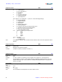
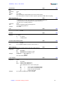
2 – Parameters description
2.1 – Motor parameters
Synchronous motor parameters
PNU :
700, 701, 702
Defines the parameters required for driving synchronous motors. These parameters can be calculated by the
auto-phasing procedure.
Parameter
Number of motor pole pairs (1 to 12).
Motor phase order: corresponds to the phase order (U, V, W) of the motor connection.
Sensor adjustment: phase shift between resolver and motor rotor.
Conversion
Motor phase
2 possible values (0x5555 or 0xAAAA).
Sensor adjustment 5.4931640625e-3*(number of pole pairs). The
value obtained is the shift in electrical degrees.
Execution
With disabled amplifier.
Auto-phasing
Parameter
Limitation
Note
PNU :
704
None.
Writing only.
This procedure allows the automatic calculation of the motor parameters:
- number of motor pole pairs,
- motor phase order,
- resolver offset.
The motor must first be disabled and uncoupled from the mechanical load. The
ENABLE signal (X4 connector) must also be active. Before executing the procedure, check for
free motor shaft rotation over one revolution, that is not dangerous for the operator.
When the motor parameters are known, it is not necessary to execute the auto-phasing.
Phase lead coefficient
Parameter
16 bits. (55-7446)
Conversion
4.57771654e-5 (electrical degree/1000 rpm)
Phase shift:
tanϕ =
−7
PNU :
703
2
0,6.10 .Kt.Np. (Max. MotorSpeed)
L.Irated
Kt: motor torque constant (Nm/Arms)
Np: number of motor pole pairs
Max.MotorSpeed: maximum motor speed (rpm)
Irated: motor current (Arms)
with: 0 ≤ ϕ ≤ 45ϒ
Phase lead coefficient (electrical degree/1000 rpm):
Coef = ϕ
1000
Max.MotorSpeed
2.2 – Current parameters
Maximum current
PNU :
Defines the max. current limitation in the motor.
Parameter
1 word.
Conversion
in percentage of the amplifier current rating: x 3.051850948e-3.
Limitation
6554 (20%) to 32767 (100%)
Execution
Note
This parameter is defined according to the amplifier and motor specifications.
32
710
Chapter 5 - Parameter setting by Profibus
SMT-BD1/p - CD1-p - User manual
Rated current
PNU :
Defines the rated current limitation in the motor.
Parameter
1 word.
Conversion
in percentage of the current rating: x 3.051850948e-3.
Limitation
6554 (20 %) to 16384 (50%)
Execution
Note
This parameter is defined according to the amplifier and motor specifications.
711
I 2t mode
Parameter
712
Note
PNU :
1 word.
0
limiting mode.
1
fusing mode.
See manual of the SMT-BD1 standard amplifier for the I2t protection mode.
Current limitation
PNU :
Defines the current limitation in the motor with regard to the value defined by the maximum current.
Parameter
1 word.
Limitation
0 to 32767 (100% of Imax)
713
Current rating/Voltage identification
Gives the amplifier current rating and voltage.
Parameter
bit 4 : 0 230 V amplifier
1 400 V amplifier
715
Bits 3, 2, 1, 0
1
2
3
4
5
6
7
8
9
10
11
Limitation
PNU :
Rating (Arms) in 230 V
2.25
4.5
7.5
10.5
16.5
27
45
60
90
120
Rating (Arms) in 400 V
1.8
2.7
5.1
7.2
14
30
45
60
90
CD1-p only
The CD1-p positioner has 2 digital PI regulators for the D-Q current loops. The gains are the following:
Proportional gain for D speed loop
PNU :
716
Integral gain for D speed loop
PNU :
717
Proportional gain for Q speed loop
PNU :
718
Integral gain for Q speed loop
PNU :
719
2.3 – Application parameters
Amplifier mode
PNU :
Defines the amplifier operation mode (position, speed or torque).
Parameter
1 word
1
torque mode
2
speed mode with PI regulator
4
position mode
8
speed mode with P regulator
16
speed mode with PI2 regulator
Execution
This instruction must be executed with disabled positioner.
In standard, the amplifier is always configurated in position mode at power on.
Chapter 5 - Parameter setting by Profibus
720
33
SMT-BD1/p - CD1-p - User manual
Max. speed
Defines the maximum application speed (and the speed scale as well).
Parameter
1 word.
Limitation
This parameter varies between 100 rpm and 10000 rpm.
Execution
With disabled amplifier.
PNU :
721
Motor rotation direction
PNU :
722
This instruction allows to reverse the motor rotation direction with regard to the input command. It also reverses
the position feedback.
Parameter
1 word :
= 0: normal.
= 1: reversed.
Execution
With disabled amplifier.
Acceleration ramp
PNU :
Defines the motor acceleration or deceleration time that corresponds to the maximum speed.
Parameter
1 word.
Conversion
in second: x 0.0005
Limitation
1 (without acceleration ramp) at 65535 (#30 s).
Note
This parameter can only be used in speed mode.
723
Motor thermal sensor
Defines the motor thermal sensor type used.
Parameter
Boolean.
0
NTC sensor
1
PTC sensor
PNU :
725
Brake delay active
Defines the time between the brake release and the amplifier disabling.
Parameter
1 word
Unit
ms
Limitation
0-16000
PNU :
726
Brake delay inactive
Defines the time between the amplifier enabling and the brake inhibition.
Parameter
1 word
Unit
ms
Limitation
0-16000
PNU :
727
Manual brake control
This instruction enables or inhibits the brake.
Parameter
1 word.
0
inhibits the brake relay output (relay closed).
1
releases the brake relay output (relay open).
Limitation
Writing only.
PNU :
728
Saving in the EEPROM
PNU :
729
Saves all amplifier parameters in the EEPROM.
Parameter
none.
Limitation
Writing only.
Execution
With amplifier disabled.
Note
All parameters modified by the other instructions (except for the sequence parameters) are not
saved. This instruction must be used to store them definitively in the amplifier.
34
Chapter 5 - Parameter setting by Profibus
SMT-BD1/p - CD1-p - User manual
2.4 – Regulator parameters
The structure of the regulator used for the SMT-BD1/p is shown below :
KF1.s
Speed
ref.
KP2
2.π.Fev
KP1
Position input
command
Idc
s + 2.π.Fev
Ki
s
Pos. monitor
Speed
monitor
The structure of the regulator used for the CD1-p is shown below :
KA.s2
KP2.s
KF1.s
KP2
KP1
Pos.
mes.
Filter
KI
s
Measured
speed
KC
All gain parameters (KF1, KF2, KP1, KP2, KI, KA, KC and Fev) are automatically calculated during the autotuning procedure.
Proportional speed loop gain
Defines the proportional regulator gain (KP2) that acts upon the speed error.
Parameter
1 word.
Conversion
1/16
Limitation
0 to 65535
PNU :
730
Integral speed loop gain
Defines the integral regulator gain (KI) that acts upon the speed error.
Parameter
1 word.
Conversion
1/256
Limitation
0 to 65535
PNU :
731
Proportional position loop gain
Defines the proportional gain that acts upon the position error (KP1).
Parameter
1 word.
Conversion
1/65536
Limitation
0 to 65535
PNU :
732
Chapter 5 - Parameter setting by Profibus
35
SMT-BD1/p - CD1-p - User manual
Feedforward speed 1
PNU :
733
Defines the feedforward speed amplitude (KF) corresponding to the speed input command (derivation of the
position input command). This feedforward term allows to reduce the following error during the motor acceleration
and deceleration phases.
Parameter
1 word.
Conversion
1/65536
Limitation
0 to 65535
Current control low-pass filter
PNU :
734
Defines the cut-off frequency at -3 dB (Fev) of the first order filter that acts upon the current control. The value of
this parameter is depending on the selected bandwidth.
Parameter
1 word.
Conversion
Frequence (Hz) = 1000/pi*Ln(65536/parameter)
Limitation
This parameter can take a value between 2832 (1000 Hz) and 61545 (20 Hz).
Antiresonance filter
Releases or inhibits the antiresonance filter.
Parameter
1 word.
= 0: inhibits the filter,
= 1: releases the filter.
PNU :
735
Auto-tuning
PNU :
736
This procedure identifies the specific motor and load parameters and calculates the regulator gain parameters.
Parameter
1 word.
0 low bandwidth.
1 medium bandwidth.
2 high bandwidth.
3 low bandwidth with antiresonance filter.
4 medium bandwidth with antiresonance filter.
5 high bandwidth with antiresonance filter.
6 low bandwidth with high stiffness filter.
7 medium bandwidth with high stiffness filter.
8 high bandwidth with high stiffness filter.
Limitation
Writing only.
Execution
With disabled amplifier and ENABLE signal activated,
or enabled amplifier and motor at standstill (zero speed).
Note
When executing this procedure, the speed loop bandwidth can be selected (low, medium or
high). These values correspond to the cut-off frequency for a 45° speed loop phase shift.
The reading indicates the previously selected bandwidth (0, 1, 2, 3, 4 or 5).
Before executing this instruction, check for free motor shaft rotation over one revolution, that is
not dangerous for the operator.
The auto-tuning procedure is not required when the regulator parameters are known.
Feedforward acceleration gain
PNU :
737
Defines the feedforward acceleration corresponding to the acceleration input command (second derivation of the
position input command). This feedforward term allows to reduce the following error during the motor acceleration
and deceleration phases.
Parameter
word.
Conversion
1
Limitation
0 to 65535
Feedforward Speed 2 gain
PNU :
738
This gain value is equal to the damping speed gain value + Feedforward friction gain value. The feed forward
friction gain allows to cancel the load viscous friction effect (load viscous friction torque is proportional to axis
speed). This feedforward term allows to reduce the following error during the motor acceleration and deceleration
phases.
Parameter
word.
Conversion
1/16
Limitation
0 to 65535
36
Chapter 5 - Parameter setting by Profibus
SMT-BD1/p - CD1-p - User manual
Speed loop damping gain
This gain is used for getting the maximum servo loop stiffness.
Parameter
word.
Conversion
1/16
Limitation
0 to 65535
PNU :
739
2.5 – Positioner parameters
Position resolution
PNU :
740
Defines the position resolution (ppr)
Parameter
1 word.
Limitation
0, corresponding to a resolution of 65536 (full scale), or
from 512 to 65534 (always an even number).
Execution
With disabled amplifier.
Note
This position resolution consequently defines the format of both position input command and
position feedback.
Position threshold error
Defines the position error triggering threshold.
Parameter
1 word.
Conversion
See position resolution.
PNU :
741
Positioner configuration
Parameter
bit
description
0*
Negative software limit switch
1*
Positive software limit switch
4*
CLEAR input active
5*
Forward only (Position Modulo)
9*
Speed modulation
12*
Minimum Sequence Pulse
13*
“Inpos” windows
14*
CAM function
15
0 trapezoidal profile
1 S-curve profile
Note: * not available on BD1/p version 506.78
PNU :
742
User output
Defines the outputs of bits 8 to 15 of HIW.
Parameter
byte
PNU :
743
Position modulo
PNU :
745
Defines the position after which the position counter is reset at 0. This function allows to get a motor position
modulo (only useful for rotating axes).
Parameter
double word
Position CLEAR input
PNU :
746
This function is released by PNU 742 and allows to reset the position counter at this value when the CLEAR input
is activated (this value is generally 0). This function is useful for rotating axes.
Parameter
double word
Negative software limit switch
PNU :
Defines the value of the negative software limit switch which release is defined by PNU 742.
Parameter
double word
747
Positive software limit switch
PNU :
Defines the value of the positive software limit switch which release is defined by PNU 742.
Parameter
double word
748
Chapter 5 - Parameter setting by Profibus
37
SMT-BD1/p - CD1-p - User manual
2.6 – Encoder output
Encoder output resolutions
PNU :
Defines the encoder output resolution.
Parameter
1 word: encoder resolution
Limitation
The encoder resolution is limited by the maximum application speed.
Execution
Note
750
Max. speed
Max. encoder resolution
100-900
8192
900-3600
4096
3600-14000
1024
With disabled amplifier.
The encoder output is only effective after the end of the encoder output programmation
procedure.
Encoder output marker pulse
PNU :
751, 752, 753
Parameter
Number of encoder pulses (1 - 16).
Phase shift with regard to the resolver marker pulse (0 - 65535).
Marker pulse width (16 - 32767).
Conversion
Marker pulse phase shift: 65536 is equivalent to 360°.
Marker pulse width: 65536 is equivalent to 360°.
Limitation
Number of encoder pulses: 1 - 16.
Phase shift with regard to the resolver marker pulse: 0 - 65535.
Marker pulse width: 16 - 32767.
Note
The amplifier takes into account the phase shift value with regard to the resolver marker pulse
and the number of marker pulses during the homing procedure.
The encoder output only takes into account these values after the end of the procedure
"encoder output programmation".
Encoder output programmation
PNU :
This procedure programs the encoder output with the parameters defined above.
Limitation
Writing only.
Execution
With disabled amplifier.
Note
The execution of this procedure takes approximately 5 s.
754
2.7 – Options
Minimum SEQ Pulse
PNU :
Allows to define the minimum duration of the SEQ output. This function is released by PNU 742.
Parameter
word
Limitation
0 - 16000 ms
756
"Inpos" window
PNU :
Defines a position window in which the INPOS signal is released. This possibility is released by PNU 742.
Parameter
word
Limitation
0 - 16000 ms
0 means no minimum duration for the SEQ output.
757
CAM position 1 and 2
PNU :
758, 759
Defines the positions between which bit 0 of the outputs (bit 8 of HIW) is activated. This possibility is released by
PNU 742.
Parameter
double word
38
Chapter 5 - Parameter setting by Profibus
SMT-BD1/p - CD1-p - User manual
2.8 – Manual motion parameters
Manual motion speed
PNU :
Parameter
Speed in rpm.
Limitation
1 - 10000 according to the value of the "Max. speed" parameter.
Note
This value depends on the value of the "Max. speed" parameter.
760
Acceleration ramp in manual motion
PNU :
Parameter
This parameter, defined in ms, corresponds to the acceleration time at max. speed.
Limitation
1 - 16000
Note
The minimum value depends on the motor and on the system inertia.
761
Deceleration ramp in manual motion
PNU :
762
Parameter
This parameter, defined in ms, corresponds to the deceleration time between max. speed and
standstill.
Limitation
1 - 16000
Note
The minimum value depends on the motor and on the system inertia.
Speed in jog
Parameter
Limitation
Note
PNU :
Speed in rpm.
1 - 10000 according to the value of the "Max. speed" parameter.
This value depends on the value of the "Max. speed" parameter.
763
Acceleration ramp in jog
PNU :
764
Parameter
This parameter, defined in ms, corresponds to the acceleration time from standstill up to max.
speed.
Limitation
1 - 16000
Note
The minimum value depends on the motor and on the system inertia.
Deceleration ramp in jog
PNU :
765
Parameter
This parameter, defined in ms, corresponds to the deceleration time from max. speed down to
standstill.
Limitation
1 - 16000
Note
This parameter is also used for emergency stops with programmed braking.
Homing configuration
PNU :
766
This parameter defines the configuration of a manual homing.
Parameter
bit
description
3
Dir
4
Switch
5
Zero
6
Origin
7
Reset
Note
The motion speed and the acceleration and deceleration ramps are those of the manual motion.
Positioner software version
Reading of the positioner software version.
Parameter
32 bits in hexadecimal.
Example
Version 506.78 is coded as 0x00050678
PNU :
770
Profibus software version
Software version reading of the positioner Profibus interface.
Parameter
16 bits in hexadecimal.
Example
Version 3.01 is coded as 0x0301
PNU :
771
Chapter 5 - Parameter setting by Profibus
39
SMT-BD1/p - CD1-p - User manual
Amplifier error code
Reading of the amplifier error code.
Parameter
3 bytes
Byte 1 (low weight):
Bits
Meaning
0
1
I2t
2
RDC
3
POS
4
MEM
5
BUS
6
7
BUSY
PNU :
773
Descriptions
I2t
Resolver converter error
Position following error
Memory error
Profibus DP mode error
Procedure error
Byte 2:
Bits
0
1
2
3
4
5
6
7
Meaning
Descriptions
POWER
RES
AP
ST
24 V (CD1-p)
TMOT
CDG
Power stage error
Resolver cable interruption error
Power undervoltage error
Amplifier temperature error
24 V error
Motor temperature error
Watchdog error
Byte 3 (high weight):
Bits
Meaning
0
HOME
1
E2PPAR
2
E2PSEQ
3
4
SEQWR
5
6
7
Descriptions
Homing procedure timeout error
Parameters EEPROM checksum error
Sequences EEPROM checksum error
Sequence writing error
Motor position
Reading of the motor position.
Parameter
32 bits
PNU :
774
Resolver value
PNU :
Reading of the value provided by the resolver. This value is an absolute position over one revolution.
Parameter
16 bits
775
Speed monitor
Motor speed monitor.
Parameter
integer.
0x7FFF corresponds to the maximum motor speed.
776
PNU :
Current monitor
PNU :
Motor current monitor.
Parameter
integer.
0x7FFF corresponds to the maximum current (= rating) in the motor.
40
777
Chapter 5 - Parameter setting by Profibus
SMT-BD1/p - CD1-p - User manual
Error code
PNU :
Extra Error code for CD1-p.
Parameter
word.
Bit
0-2: 2 Power voltage error
3
Out of 24 Vdc range (18 V to 29 V)
4
Motor phases/earth short-circuit.
5
Braking system error
6
Fan error
7
Motor holding brake error
Bit 3:
IGBT module error
Bit 4:
Power undervoltage. This error has no influence on the AOK signal
Bit 9:
400 V power stage initialization error
Bit 10: Power configuration error
Bit 11: Current measurement offset error
Bit 15: Current error
778
2.9 – Sequence Reading/Writing
A sequence is defined by a list of parameters (PNU 782 to PNU 793):
- Sequence control
- Position
- Speed
- Acceleration
- Deceleration
- Delay time
- Link
- Counter
- Counter link
- Condition
- Logic outputs
- Output position
CAUTION !
When the parameter " position resolution " is modified, all position values in the sequences are also modified.
When the parameter "Max. motor speed" is modified, all speed parameters in the sequences are modified as
well. Consequently, when the sequences parameters are sent to the positioner, it must be previously
programmed with the correct parameters "position resolution" and "max. motor speed".
All sequences are saved in the EEPROM. The direct access to a sequence is not possible. The transfer requires
a buffer: the command PNU 780 allows to transfer the EEPROM parameters to the buffer and the command PNU
781 allows to transfer the buffer parameters to the EEPROM. The writing or reading of the buffer parameters are
made by the commands PNU 782 to PNU 793.
Reading of a sequence
PNU :
780
Parameter
0-127 sequence number
Note
This instruction transfers the sequence parameters from the EEPROM to the buffer. This allows
the parameter values to be read in the buffer (see below).
Writing of a sequence
PNU :
781
Parameter
0-127 sequence number
128
checksum
Note
This instruction transfers the sequence parameters from the buffer to the EEPROM. The
sequence parameters must of course be previously written in the buffer (see below).
When all sequences are written, a sequence must be written with a value of 128; this
allows to update the checksum in the EEPROM (otherwise, the amplifier will indicate an
EEPROM fault at its next powering).
The writing in the EEPROM is not instantaneous; wait at first for the amplifier reply before
writing other parameters.
All instructions below allow the access to the parameters of the sequence contained in the buffer.
Chapter 5 - Parameter setting by Profibus
41
SMT-BD1/p - CD1-p - User manual
Sequence control
Parameter
bit
0
1
2
3
Note
PNU :
782
description
1 = valid sequence
0 = non valid sequence
0 = positioning
1 = homing
0 = absolute positioning
1 = relative positioning
1 = speed sequence
If the sequence is a homing (bit 1 = 1), bits 3 to 7 have following meanings:
3
0 = positive direction
1 = negative direction
4
0 = without switch
1 = with switch
5
0 = without marker pulse
1 = with marker pulse
6
0 = stops the motor after the home position found
1 = positions the motor on the home position
7
0 = does not reset the position counter
1 = resets the position counter
8 -11
define the triggering for the logic inputs:
0
End
1
Begin
2
Stop
3
Speed
4
Pos
12-14 reserved.
15
= 0 conditional start
= 1 conditional stop
To invalidate a sequence, just send this instruction with the value 0; the other parameters will be
ignored.
Sequence position
PNU :
This parameter defines the position for a positioning (absolute or relative) or the Reset value for a homing.
Parameter
double word
Unit
depends on the position resolution
Variation
(-32768 x resolution) to (32768 x resolution - 1)
783
Sequence speed
PNU :
784
Defines the motion speed.
Parameter
word
Unit
rpm
Variation
1 at max. speed for a positioning; can be negative if the sequence is a speed sequence.
Note
This parameter is saved in % with regard to the max. application speed parameter, even if the
speed is indicated in rpm. If this parameter is modified, all speed parameters of all sequences
must be sent again.
Acceleration
PNU :
785
This parameter defines the positioning acceleration ramp. For speed sequences, it defines the real acceleration
time.
Parameter
word
Unit
ms
Variation
1 to 16000
Note
The real minimum value depends on the motor and the inertia.
42
Chapter 5 - Parameter setting by Profibus
SMT-BD1/p - CD1-p - User manual
Deceleration
PNU :
786
This parameter defines the positioning deceleration ramp. For speed sequences, it defines the actual deceleration
time.
Parameter
word
Unit
ms
Variation
0 to 16000
Note
The real minimum value depends on the motor and the inertia.
The value 0 allows to link up to another sequence (parameter Link) without stopping.
Delay time/Time out
PNU :
This parameter defines either:
- a delay time at the end of the positioning, for a positioning sequence or,
- a movement time at constant speed for a speed sequence or,
- the time out for a homing sequence.
Parameter
word
Unit
ms for the positioning and speed sequences
s for the homing sequences
Variation
0 to 16000
787
Link
Parameter
PNU :
788
PNU :
789
Counter link/conditional jump
Parameter
0-127 number of the link sequence
-1
no link
Note
For a conditional jump, the counter value must be -1
PNU :
790
Start conditions
This parameter defines the condition inputs for the start of this sequence.
Parameter
word
bit
description
0-7
The inputs 0 to 7 must be set at 0.
8-15
The inputs 0 to 7 must be set at 1.
Example
Conditions:
bits 1 and 3 = 1
bit 6 = 0
The value will be 0x0A40
PNU :
791
Logic outputs
PNU :
This parameter defines the effect on the logic outputs in this sequence.
Parameter
word
bit
description
0-7
mask s for the outputs 0 to 7.
8-15
mask r for the outputs 0 to 7.
The combination of the s and r masks gives:
rs
01
->
sets at 1 the corresponding output.
00
->
sets at 0 the corresponding output.
10
->
keeps the output unchanged.
11
->
reverses the output.
Example
If no output is modified, the value is 0xFF00
792
Counter
Parameter
Variation
0-127
-1
number of the link sequence
no link
word
1 - 32767
0
no counter
-1
conditional link
Chapter 5 - Parameter setting by Profibus
43
SMT-BD1/p - CD1-p - User manual
Triggering position
PNU :
Defines the position that triggers the inputs when the motor passes this position.
Parameter
double
Note
This parameter is only effective when the inputs triggering type is a position.
793
Torque input command
PNU :
Defines the torque value in percentage for a torque sequence.
Parameter
word
Note
0x7FFF corresponds to the max. current defined by PNU 710.
794
Modification of sequence position
PNU :
796
This parameter directly modifies the position parameter of a sequence in the RAM; the sequence must be valid.
This modification has an immediate result.
Parameter
double word
Home (PKW)
number of the sequence to be modified.
Unit
depends on the position resolution.
Variation
(-32768 x resolution) to (32768 x resolution - 1)
Note
This position value is not saved in the EEPROM; consequently, it will be lost at the power supply
cut-off. At the next power up, find the position at the former saved value by command PNU 781.
But a sequence position must not be modified during a sequence execution.
Modification of a sequence speed
PNU :
797
This parameter directly modifies the speed parameter of a sequence in the RAM; the sequence must be valid.
This modification has an immediate result.
Parameter
word
Home (PKW)
number of the sequence to be modified.
Unit
rpm
Variation
1 to max. speed for a positioning; can be negative if the sequence is a speed sequence.
Notes
Eventhough the speed may be given in rpm, this parameter is saved in % with regard to the
application maximum speed parameter. If this parameter is modified, all speed parameters of all
sequences must be sent again.
This speed value is not saved in the EEPROM. Consequently, it will be lost at the power supply
cut-off. At the next power up, find the former saved speed value by command PNU 781.
But a sequence speed must not be modified during the execution.
44
Chapter 5 - Parameter setting by Profibus
SMT-BD1/p - CD1-p - User manual
Chapter 6 - Fault finding
1 - DIAGNOSTICS
A fault diagnostic can be made:
- by display: front panel LED display.
- by serial link: clear fault display by the BD1 m PC software.
- by Profibus link: by error code.
At an error triggering, the amplifier is disabled.
1.1 - SMT-BD1/p fault LEDs
5 red LEDs are available on the SMT-BD1/p front panel. They are indicating the fault type:
ON
SYS
coded faults
PROTECTION
Amplifier rated current overload:
- blinking display = Idyn signal (I2t threshold is reached)
- continuous display = amplifier disabled (I2t fault)
PROFIBUS fault (DP mode)
DISPLAY CODE
LED
I 2t
z
Profibus
z {
{ z
{ {
{ z
Position following error
Position
Resolver cable interruption
Resolver
z
Power stage
z z
Power stage failure:
- power supply overvoltage
- internal switch protection
- short circuit between phases
Resolver converter failure
R.D.C
Amplifier overtemperature
°C Amp.
Power supply undervoltage
Undervolt.
Motor overtemperature
°C Motor
Fault of the amplifier parameter memory
NovRAM
Amplifier automatic procedure:
- blinking display = procedure running
- continuous display = operating error
: Led is unlit
Busy
z
z
z
z
z
z
z
z
z
z
z
z
z
z
z
z : Led is lit
All these faults are stored in the amplifier, except for the "Undervolt." and "Profibus" faults.
1.2 - CD1-p fault LEDs
Only 3 red fault LEDs are available on the CD1-p front panel:
(green) ON
Chapter 6 – Fault finding
SYS (yellow)
(red) ERROR
AP (red)
(green) BUS
BUSY (yellow)
45
SMT-BD1/p - CD1-p - User manual
1.3 – Fault reset
The reset of a stored fault can be made:
- via the fault RESET input of X4, pin 13 (only on SMT-BD1/p),
- via the serial link,
- by the control issued from Profibus,
- by switching off the amplifier power supply.
2 – FAULT FINDING
2.1 – System fault
If the red "SYS" LED is lit at power on, the logic board is defective.
- Check that the EPROM (firmware memory) is correctly plugged on the amplifier.
- Check that the EPROM version is actually 50x.x8 on the SMT-BD1/p series and 51x.x8 on the CD1-p series.
- Check for no conducting dust that may involve short-circuits on the amplifier logic board.
2.2 – Non stored faults
2.2.1 – Bus fault (Profibus)
This fault is only displayed when the Profibus communication is interrupted.
The fault is cancelled as soon as the communication is restored.
2.2.2 - "UNDERVOLT." fault
-
If the fault occurs at the amplifier commissioning:
* Check that the power supply is on.
2.3 – Stored faults
If a fault occurs on the amplifier, it can generate the detection of several other faults which are only a
consequence of the initial one. In order to make diagnostic and maintenance easier, the faults are displayed and
processed with the priority described below. For safety reasons, the power must be turned off for the cancelling of
some faults that requires the handling of the amplifier; in this case, the RESET is automatic when power is turned
on again. If power is not turned off, do not forget to make a RESET immediately after the fault is cancelled.
2.3.1 - "Busy" fault
-
If the BUSY fault is continuously displayed after applying power to the amplifier, the AUTOTEST procedure
has failed and the amplifier is not ready for operation.
-
If the BUSY fault is continuously displayed after the execution of the AUTOPHASING function, the
procedure has failed because of an external cause and the calculated parameters are wrong. Check that the
ENABLE input is actually activated. Then check that the motor is unloaded and the shaft movement is free
during the procedure.
-
If the BUSY fault is continuously displayed after the execution of the AUTOTUNING function, the
procedure has failed because of an external cause and the calculated parameters are wrong. Check that the
ENABLE input is actually open.Then check that the motor is unloaded and the shaft movement is free during
the procedure.
-
This fault may also occur during a homing procedure which "time out" is too low.
2.3.2 - "EEPROM" fault
-
Check for the presence of the EEPROM and check its correct orientation.
-
If the fault remains, the EEPROM is not correctly initialized (CHECKSUM) or is not compatible with the
amplifier software.
-
This fault may occur if the motor is enabled during a parameter saving or during a sequences transfer between
PC and amplifier.
-
To cancel this fault, if it is:
46
Chapter 6 – Fault finding
SMT-BD1/p - CD1-p - User manual
* due to the parameters, renew the amplifier parameter setting and the parameter saving,
* due to the sequences, send the sequences to the amplifier again.
2.3.3 - "°C MOTOR" fault
-
If the fault occurs when commissioning the amplifier:
* Check the configuration of the MN and OP jumpers with regard to the type of thermal switch used in the
motor.
* Check the connection between the thermal switch and the amplifier on the X1 front panel connector or the
X6 rack rear connector.
-
If the fault occurs during the operation:
* Check the motor temperature and look for the reason of this overheating (mechanical shaft overload, duty
cycle too high, ...).
2.3.4 - "°C AMP." FAULT
Check for the correct fan type with regard to the rated current required.
2.3.5 - "POWER STAGE" fault
-
If the fault occurs at the amplifier commissioning:
* Check the DC bus voltage and the terminal voltage of the power transformer secondary
(DC bus < 370 VDC and V secondary < 260 VAC).
-
If the fault occurs during the operation:
* Check the braking system operation during the motor braking phases.
* Check the sizing of the braking resistor with regard to the motor braking phases.
* Check for the correct current cycle required with regard to the current table.
* Check for no short-circuit in the motor wiring and at the motor terminals.
2.3.6 - "RESOLVER" fault
-
Check the resolver connection on the amplifier connector X1.
-
Check for the presence of the P-RES components.
-
Check that the resolver type is correct with regard to the P-RES components (see chapter 2, section 1).
-
Check the connections between the resolver and the amplifier and at the resolver terminals.
2.3.7 - "R.D.C." fault
-
If the fault occurs at the amplifier commissioning:
* Check that the values of the P-RES components with regard to the resolver transformation ratio are correct.
-
If the fault occurs during the operation:
* Check that the motor speed does not exceed the speed limit defined below.
If Maximum speed < 900 rpm, then the speed limit = 900 rpm.
If 900 rpm < Maximum speed < 3600 rpm, then the speed limit = 3600 rpm.
If 3600 rpm < Maximum speed < 14000 rpm, then the speed limit = 14000 rpm.
Be careful about the torque mode operation where the motor speed is determined by the load.
2.3.8 - "I2t" fault
-
Check the rated current value required with regard to the table of currents authorized in pulse mode cycle.
-
Check the rated current of the amplifier defined in the Rated current parameter with regard to the current
required for the operation cycle.
Chapter 6 – Fault finding
47
SMT-BD1/p - CD1-p - User manual
3 – OPERATING PROBLEMS
3.1 – Motor does not move
-
Check that the amplifier is on.
-
Check that the power supply is on.
-
Check the amplifier fuses (F1 and F2) and the motor connection.
-
Check the logic wiring of the signals FC+, FC- and ENABLE.
-
Check that the amplifier is enabled.
3.2 – Motor supplied but no torque
-
Check that the Maximum current and Rated current parameters have no zero value.
3.3 – Shaft locked, eratic oscillations or rotation at maximum speed
-
Check the resolver wiring on the X1 connector and the mechanical mounting of the resolver on the motor.
-
Check the value of the motor parameters (number of pole pairs, resolver wiring, motor phase).
3.4 – Discontinuous motor rotation with zero torque positions
-
Check the connection of the three phases cables between motor and amplifier.
3.5 – Loud crackling noise in the motor at standstill
-
Check that the Motor-Amplifier-Controller ground connections comply with the recommendations
3.6 – Loud noise in the motor at standstill and when running
-
Check the rigidity of the mechanical transmission chain between motor and load (backlash and elasticity in
the gearboxes and couplings).
-
Execute the AUTOTUNING command again by choosing a lower bandwidth (Medium or Low).
3.7 – Sequence not executed
In "operation enabled" status, the motor does not move at a sequence start in following cases:
•
If, after power on, the operator wants to start a positioning sequence whereas sequence 0 is a homing
sequence that is not yet executed.
•
A start condition has been defined for this sequence and is not fulfilled.
•
One or two limit switches activated.
4 - SERVICE AND MAINTENANCE
When exchanging an amplifier on a machine, proceed as follows:
- Check that the new amplifier has the same hardware configuration as the old amplifier (including its address),
- Plug the parameters EEPROM of the old amplifier on the new one.
The new amplifier is configurated like the old one.
48
Chapter 6 – Fault finding
SMT-BD1/p - CD1-p - User manual
Appendix
1 – CURRENT LOOPS ADJUSTMENT (SMT-BD1/p)
For the BL and MA MAVILOR motor series, the current loop adjustments are made by means of the B1, B2, B3
jumpers or by the customization boards PC1, PC2, PC3, PC4 according to the table below:
MOTOR
MA 3
MA 6
MA 10
MA 20
MA 30
MA 45
MA 55
BL 55-3
BL 55-5
BL 71
BL 72
BL 73
BL 74
BL 111
BL 112
BL 113
BL 114
BL 115
BL 141
BL 142
BL 143
BL 144
(*) :
AMPLIFIER
4A
8A
12 A
B1
B1
B2
B2
B1
B1
B1
17 A
30 A
B1
B1
B2
B1
B1
B2
B2
45 A
60 A
70 A
100 A
B1
B2
B2
B2
B1
B1
B1
B2
PC1*
PC2*
PC4*
PC1*
PC3*
B2
B2
B2
B2
B2
B2
B2
B2
B2
B1
B2
B1
B1
PC4*
PC2*
PC3*
PC2*
PC1*
PC1*
PC1*
B1
B1
B2
B2
B2
B2
B1
B2
B3
B1
B1
B1
B1
B2
B3
PC1 : RA = 270 KΩ / CA = 470 pF / C14 = 82 pF
PC3 : RA = 160 KΩ / CA = 680 pF / C14 = 150 pF
B1
B1
B1
B1
B2
B3
B3
B2
B3
B3
B2
B2
B2
B3
B3
B2
B3
B2
B2
PC2 : RA = 220 KΩ / CA = 560 pF / C14 = 100 pF
PC4 : RA = 120 KΩ / CA = 820 pF / C14 = 150 pF
The adjustment of the current loop P.I. regulators according to the power board current rating and to the motor
phase-phase inductance is made as follows:
Calculation of G = 1,4 x C x I
with
C = current rating (A)
I = phase-phase inductance (mH),
4 A, 8 A, 12 A AND 17 A AMPLIFIERS
If G < 60, current loop jumpers (x3) on B3 position,
If 60 < G < 100, current loop jumpers (x3) on B2 position,
If G > 100, current loop jumpers (x3) on B1 position.
30 A, 45 A AND 60 A AMPLIFIERS
If G < 100, current loop jumpers (x3) on B3 position,
If 100 < G < 250, current loop jumpers (x3) on B2 position,
If G > 250, current loop jumpers (x3) on B1 position.
70 A AND 100 A AMPLIFIERS
Calculation of the RA, CA and C14 components of the current loops,
RA = G KΩ, CA = 130 / G nF, C14 = CA / 6 nF
Appendix
49
SMT-BD1/p - CD1-p - User manual
2 – USE OF THE BD1m PC OSCILLOSCOPE
Under Windows 95/98, switch to full screen mode before using the oscilloscope.
Oscilloscope screen (F8 in the main menu):
Triggering moment
cursor
Channel selector
Function keys
Triggering level
cursor (trigger)
Keys F1 and F2 modifiy the time basis.
Keys F3 and F4 modify the amplitude of the channel indicated by the "channel selector".
Key F5 sets the "channel selector" on channels 1, 2 or 3.
Key F6 allocates a signal to the channel indicated by the "channel selector":
signal
Speed Mon
Speed ref
Imon
Iref
Iq
Id
I 2t
resolver
Error Pos
Scale factor
10 V for max. speed
rpm
10 V for rating
10 V for rating
10 V for rating
10 V for rating
65536 ppr
position resolution
Meaning
speed monitor
speed input command applied to the speed loops
current monitor
current input command applied to the current loops
quadrature current monitor
direct current monitor
current consumption
position provided by the resolver
following error
Key F8 modifies the operation mode:
- Continue: Continuous signal acquisition and display.
- Single Trigger: one single triggering (single-strike).
- Continuous Trigger: continuous triggering.
50
Appendix
SMT-BD1/p - CD1-p - User manual
Key F9 allows to define the triggering mode:
- on positive level,
- on negative level,
- on rising edge,
- on descending edge,
- on an amplifier fault.
In mode "Continuous Trigger" or "Single Trigger", key Alt-F3 allow to save the oscilloscope curves in a file and key
Alt-F2 allows to reload these files. These files are compatible with the BPCW 2.6 software.
Note
The SMT-BD1/p has got two oscilloscope channels in « continuous » mode and three channels with the
"continuous trigger mode" and "single trigger".
Appendix
51