1
User manual
Interroll
ConveyorControl system
Chapter-ID: User manual
Chapter-ID: Version
Chapter-ID: Translation of the original instructions
Version 2.0 (04/2013) en
Translation of the original
instructions
Manufacturer's address
Interroll Engineering GmbH
Hoeferhof 16
D-42929 Wermelskirchen
Tel. +49 2193 23 0
Fax. +49 2190 2022
www.interroll.com
Copyright
The copyright of this manual remains with Interroll Engineering GmbH. The
operating instructions contain technical regulations and drawings which may not
be reproduced partially or in full, transmitted by any means, utilized without
permission for competitive purposes or disclosed to third parties.
Version 2.0 (04/2013) en
Translation of the original instructions
ConveyorControl
Table of contents
Introduction
Information about the manual . . . . . . . . . . . . . . . . . . . . . . . . . . . . . . . . . . . 3
Warning notices in this manual. . . . . . . . . . . . . . . . . . . . . . . . . . . . . . . . . . 3
Further symbols . . . . . . . . . . . . . . . . . . . . . . . . . . . . . . . . . . . . . . . . . . . . . 4
Safety
General safety instructions .
Intended use . . . . . . . . . . .
Unintended use . . . . . . . . .
Qualified persons . . . . . . . .
Dangers . . . . . . . . . . . . . . .
Interfaces to other devices .
Operating modes . . . . . . . .
.
.
.
.
.
.
.
.
.
.
.
.
.
.
.
.
.
.
.
.
.
.
.
.
.
.
.
.
.
.
.
.
.
.
.
.
.
.
.
.
.
.
.
.
.
.
.
.
.
.
.
.
.
.
.
.
....
....
....
....
....
....
....
...
...
...
...
...
...
...
....
....
....
....
....
....
....
...
...
...
...
...
...
...
....
....
....
....
....
....
....
...
...
...
...
...
...
...
....
....
....
....
....
....
....
...
...
...
...
...
...
...
5
5
5
5
6
6
7
.
.
.
.
.
.
.
.
.
.
.
.
.
.
.
.
.
.
.
.
.
.
.
.
.
.
.
.
.
.
.
.
.
.
.
.
.
.
.
.
.
.
.
.
.
.
.
.
.
.
.
.
.
.
.
.
.
.
.
.
.
.
.
.
.
.
.
.
.
.
.
.
.
.
.
.
.
...
...
...
...
...
...
...
....
....
....
....
....
....
....
...
...
...
...
...
...
...
....
....
....
....
....
....
....
... 8
. . 10
. . 14
. . 15
. . 16
. . 16
. . 17
Product information
Product description . . . .
Description of functions .
Structure . . . . . . . . . . . .
Scope of delivery . . . . . .
Label . . . . . . . . . . . . . . .
Technical specifications .
Dimensions . . . . . . . . . .
.
.
.
.
.
.
.
.
.
.
.
.
.
.
.
.
.
.
.
.
.
.
.
.
.
.
.
.
.
.
.
.
.
.
.
.
.
.
.
.
.
.
.
.
.
.
.
.
.
.
.
.
.
.
.
.
.
.
.
.
.
.
.
.
.
.
.
.
.
.
Transport and storage
Ambient conditions for transport and storage . . . . . . . . . . . . . . . . . . . . . . 18
Transport . . . . . . . . . . . . . . . . . . . . . . . . . . . . . . . . . . . . . . . . . . . . . . . . . 18
Storage . . . . . . . . . . . . . . . . . . . . . . . . . . . . . . . . . . . . . . . . . . . . . . . . . . 18
Planning
General information . . . . . . . . .
Install software . . . . . . . . . . . . .
Basics . . . . . . . . . . . . . . . . . . .
Start the Configurator. . . . . . . .
User interface . . . . . . . . . . . . .
Functional concept . . . . . . . . . .
Constructing the conveyor line .
Preparing to Address . . . . . . . .
Parameterizing modules. . . . . .
Overview of parameters . . . . . .
..
..
..
..
..
..
..
..
..
..
...
...
...
...
...
...
...
...
...
...
....
....
....
....
....
....
....
....
....
....
...
...
...
...
...
...
...
...
...
...
....
....
....
....
....
....
....
....
....
....
...
...
...
...
...
...
...
...
...
...
....
....
....
....
....
....
....
....
....
....
...
...
...
...
...
...
...
...
...
...
....
....
....
....
....
....
....
....
....
....
..
..
..
..
..
..
..
..
..
..
19
19
20
22
23
25
26
30
32
35
Warning information for assembly . . . . . . . . . . . . . . . . .
Assembly of ConveyorControl modules . . . . . . . . . . . . .
Warning information relating to the electrical installation
Electrical installation . . . . . . . . . . . . . . . . . . . . . . . . . . .
Example of connection . . . . . . . . . . . . . . . . . . . . . . . . . .
....
....
....
....
....
...
...
...
...
...
....
....
....
....
....
..
..
..
..
..
41
41
43
44
52
....
....
....
....
....
...
...
...
...
...
....
....
....
....
....
..
..
..
..
..
53
53
57
58
60
Assembly
Initial startup and operation
Initial startup . . . . . . . . .
Addressing modules. . . .
Downloading parameters
Self-test . . . . . . . . . . . . .
Operation . . . . . . . . . . . .
...
...
...
...
...
....
....
....
....
....
...
...
...
...
...
....
....
....
....
....
...
...
...
...
...
....
....
....
....
....
...
...
...
...
...
Maintenance and cleaning
Warnings concerning maintenance and cleaning . . . . . . . . . . . . . . . . . . . 61
Maintenance . . . . . . . . . . . . . . . . . . . . . . . . . . . . . . . . . . . . . . . . . . . . . . 61
Cleaning . . . . . . . . . . . . . . . . . . . . . . . . . . . . . . . . . . . . . . . . . . . . . . . . . 61
Version 2.0 (04/2013) en
Translation of the original instructions
1
ConveyorControl
Table of contents
Troubleshooting
Meaning of the LEDs. . . . . . . . . . . . . . . . . . . . . . . . . . . . . . . . . . . . . . . . . 62
Troubleshooting . . . . . . . . . . . . . . . . . . . . . . . . . . . . . . . . . . . . . . . . . . . . 66
Abandonment and disposal
Shut-down. . . . . . . . . . . . . . . . . . . . . . . . . . . . . . . . . . . . . . . . . . . . . . . . . 68
Disposal . . . . . . . . . . . . . . . . . . . . . . . . . . . . . . . . . . . . . . . . . . . . . . . . . . 68
Appendix
Accessories . . . . . . . . . . . . . . . . . . . . . . .
Possible wiring of the inputs . . . . . . . . . . .
Possible wiring of the ComControl outputs
Glossary of parameters . . . . . . . . . . . . . . .
Electrical data of connectors . . . . . . . . . . .
Installation declaration . . . . . . . . . . . . . . .
2
.
.
.
.
.
.
.
.
.
.
.
.
.
.
.
.
.
.
.
.
.
.
.
.
.
.
.
.
.
.
.
.
.
.
.
.
.
.
.
.
.
.
.
.
.
.
.
.
.
.
.
.
.
.
.
.
.
.
.
.
.
.
.
.
.
.
.
.
.
.
.
.
.
.
.
.
.
.
.
.
.
.
.
.
.
.
.
.
.
.
.
.
.
.
.
.
.
.
.
.
.
.
.
.
.
.
.
.
.
.
.
.
.
.
.
.
.
.
.
.
.
.
.
.
.
.
.
.
.
.
.
.
.
.
.
.
.
.
.
.
.
.
.
.
69
70
80
82
89
90
Version 2.0 (04/2013) en
Translation of the original instructions
ConveyorControl
Introduction
Information about the manual
Contents
Validity of the manual
This manual contains important advice, notes and information about the
ConveyorControl in all phases of its life cycle:
• Transport, assembly and start-up
• Safe operation, maintenance and troubleshooting, disposal
• Accessories
The manual describes the ConveyorControl as it is delivered by Interroll.
In addition to this manual, special contractual agreements and technical
documents apply to special versions.
The manual is part of the
product
For trouble-free, safe operation and warranty claims, read the manual and
follow the instructions before handling the ConveyorControl.
Keep the manual near to the ConveyorControl.
Pass the manual on to any subsequent operator or occupant of the
ConveyorControl.
Interroll does not accept any liability for faults or defects due to nonobservance of this manual.
If you have any questions after reading the operation manual, feel free to
contact our customer service. See the last page for your local contact
information.
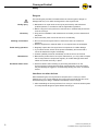
Warning notices in this manual
The warning notices in this document refer to risks which may arise during usage
of the ConveyorControl. The relevant warning notices are explained in the
chapter on safety (see "Safety", page 5) and at the beginning of each chapter.
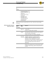
There are three categories of danger. The following signal words are used in the
document as required:
• Danger
• Warning
• Caution
Signal word
Meaning
Danger
Indicates a hazardous situation which, if not
avoided, will result in death or serious injury.
Warning
Indicates a hazardous situation which, if not
avoided, could result in death or serious injury.
Caution
Indicates a hazardous situation which, if not
avoided, may result in minor or moderate injury.
Structure of warning notices
DANGER
Nature and source of the hazard
Possible consequence of non-observance
Information about how to avoid the hazard.
Version 2.0 (04/2013) en
Translation of the original instructions
3
ConveyorControl
Introduction
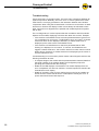
Further symbols
This symbol identifies possible material damage.
Information about how to avoid the damage.
Important
This symbol displays safety instructions.
Hint
This symbol marks useful and important information.
This symbol marks the steps that have to be carried out.
Italics designate a term from the software interface.
4
Version 2.0 (04/2013) en
Translation of the original instructions
ConveyorControl
Safety
General safety instructions
The ConveyorControl has been built to comply with the state of the art.
Nevertheless,users may encounter hazards during use:
• Risks of physical injury to the user or bystanders
• Adverse effects of the ConveyorControl and other circumstances.
Important
Disregarding the warning notices in this manual may lead to serious injury.
Always read the entire operating and safety instructions before starting to
work with the ConveyorControl and follow the information contained therein in
full.
Only instructed and qualified persons may work with the ConveyorControl.
Always keep the manual at hand when working at the ConveyorControl so you
can consult it quickly if required.
Always comply with relevant national safety regulations.
If you have any questions after reading the operation manual, feel free to
contact our customer service. See the last page for your local contact
information.
Intended use
The ConveyorControl may only be used for industrial applications and in an
industrial environment to control the RollerDrive EC310.
The ConveyorControl must be integrated into a conveyor or conveyor system.
Any other use is considered inappropriate.
Any modifications that affect the safety of the product are not permitted.
The ConveyorControl must only be operated within the defined operating limits.
Unintended use
Use for anything other than the intended purpose requires approval by Interroll.
Qualified persons
Qualified persons are persons who read and understand the manual and, taking
national regulations into account, can competently execute incidental work.
Only instructed and qualified persons may work with the ConveyorControl
system, taking the following into account:
• the relevant manuals and diagrams,
• the warning and safety instructions in this manual,
• the system specific regulations and requirements,
• national or local regulations and requirements for safety and accident
prevention.
Version 2.0 (04/2013) en
Translation of the original instructions
5
ConveyorControl
Safety
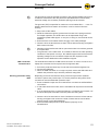
Dangers
Important
The following list provides information about the various types of danger or
damage that may occur while working with the ConveyorControl.
Bodily injury
Electricity
Working environment
Faults during operation
Maintenance
Accidental motor starts
Maintenance or repair work must only be performed by authorized and
qualified persons in accordance with the applicable regulations.
Before using the ConveyorControl, ensure that no unauthorized persons are
near the conveyor.
Only perform installation and maintenance work after you have switched off
the power.
Ensure that the power cannot be turned on accidentally.
Do not use the ConveyorControl in areas where there is a hazard of
explosion.
Remove equipment or material which is not required from the workspace.
Regularly inspect the ConveyorControl components for visible damage.
If you notice smoke, switch off the power immediately and ensure that it
cannot be switched on again accidentally.
Contact qualified personnel immediately to find the source of the fault.
Because the product does not require maintenance, you only need to inspect
the ConveyorControl components regularly for visible damage and that all
cables and screws are firmly in place.
Exercise caution when installing or performing maintenance on the
ConveyorControl components and when troubleshooting, as a start signal
may accidentally be triggered, unintentionally starting one of the connected
motors.
Interfaces to other devices
When assembling the ConveyorControl components in a conveyor, further
hazards may occur. These hazards are not part of this manual and have to be
analyzed during the design, installation and startup of the conveyor.
After assembling the ConveyorControl in a conveyor, check the whole system
for new potential dangerous spots before switching on.
6
Version 2.0 (04/2013) en
Translation of the original instructions
ConveyorControl
Safety
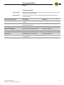
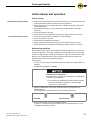
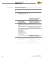
Operating modes
Normal mode
Operation following installation at the user's premises as control components in a
conveyor in a complete system.
Special mode
All operating modes which are required to guarantee and maintain safe and
normal operation.
Special operating mode
Explanation
Comment
Transport/Storage
Loading and unloading, transport and
storage
-
Assembly/Initial start-up
Installation at the end customer's and
performing the test run
When de-energized
Cleaning
External cleaning
When de-energized
Maintenance/Repairs
Maintenance and inspection tasks
When de-energized
Troubleshooting
Troubleshooting in the event of a fault
When de-energized
Fault elimination
Eliminating the fault
When de-energized
Shut-down
Dismantling from the conveyor
When de-energized
Disposal
Disposal of ConveyorControl system
and packaging
-
Version 2.0 (04/2013) en
Translation of the original instructions
7
ConveyorControl
Product information
Product description
The ConveyorControl system is a control system for conveyors which allows
many parameters to be set and can thus be used very flexibly. It can work
completely independently; following successful addressing and parameterization,
no external control computer or PLC are required.
The ConveyorControl comprises the following components:
• CentralControl or GatewayControl
• SegmentControl
• ComControl
• Configurator
• Accessories: Flat cable, power supply unit, addressing magnet
CentralControl
The CentralControl monitors the correct connection and functioning of the
individual ConveyorControl modules. It is connected via the bus communication
with these modules and can thus recognize and assess various system fault
types. The faults which occur are displayed via three LEDs.
The CentralControl must be connected to one end of the bus line. It features a
terminating resistor which is required for the bus line. A ComControl with
activated terminating resistor must be connected to the other end of the bus line.
There must be a maximum of one CentralControl per conveyor line.
SegmentControl
The SegmentControl can control one or two zones in a conveyor. A sensor must
be evaluated and a RollerDrive controlled in each zone. The functionality of the
SegmentControl can be set flexibly, e.g., the sensor logic, the parameters of the
RollerDrive and the release mode parameters can be set.
Faults which occur, e.g., in connection with the RollerDrive, sensors or release
mode are displayed via LEDs. When a fault occurs or is remedied, the
SegmentControl reacts in a specified manner which is dependent on the fault in
question and which can be set.
If two drives per zone are required in a conveyor system, a second RollerDrive
can be connected to the SegmentControl. This is designated as the "Slave
RollerDrive" and, if parameterized accordingly, receives the same commands as
the first RollerDrive.
To function within the ConveyorControl a SegmentControl requires at least one
CentralControl or GatewayControl and a ComControl.
8
Version 2.0 (04/2013) en
Translation of the original instructions
ConveyorControl
Product information
ComControl
The ComControl must control one zone. A sensor must be evaluated and a
RollerDrive controlled in each zone. In addition, two further inputs and three
outputs can be connected. The functionality and logic options of the ComControl
can be flexibly set.
The ComControl offers the option of branching off the bus line. With the
ComControl at the end of a bus line a terminating resistor can be switched on via
a dip switch. This is necessary to terminate the bus line at the end. A nonswitchable terminating resistor is integrated at the connections Data A1 and Data
A2.
Faults which occur, e.g., in connection with the RollerDrive, sensors or release
mode are displayed via LEDs and can be read out via an output which is
parameterized accordingly.
To function within the ConveyorControl a ComControl requires at least one
CentralControl or GatewayControl.
Configurator
The ConveyorControl Configurator software serves to address and parameterize
the individual modules in the ConveyorControl. The conveyor can be recreated
virtually and configured according to requirements.
Accessories
In addition to the ConveyorControl modules, further accessories are also
available from Interroll:
• Only the power supply unit ConveyorControl from Interroll may be used to
supply the power to the PowerControl modules.
• Only the flat cable from Interroll may be used for the power supply and for bus
communication.
Version 2.0 (04/2013) en
Translation of the original instructions
9
ConveyorControl
Product information
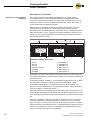
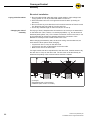
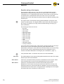
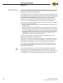
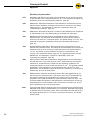
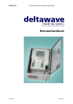
Description of functions
Zero pressure accumulation
conveying
The ConveyorControl system allows packages to be conveyed without
accumulation pressure. This means that packages are transported without
coming into contact with each other. To achieve this, the conveyor line is subdivided into zones. One zone consists of a RollerDrive, several idler rollers, a
control module and corresponding sensors.
Zero pressure accumulation conveying is achieved by there being only one
package in every zone and by the zones retaining the package until the
downstream zone is detected as being "unblocked" by the corresponding sensor.
When accumulation occurs, a signal is transmitted upstream to retain the next
package. A gap is always left between the goods being transported so that no
accumulation pressure occurs.
6
5
8
10
9
11
12
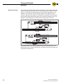
Schematic example: three zones
1
2
3
4
5
6
Zone 1
Zone 2
Zone 3
Direction of travel
Package
Package
7
8
9
bl
bm
bn
RollerDrive 1
RollerDrive 2
RollerDrive 3
Zone sensor 1
Zone sensor 2
Zone sensor 3
A package is conveyed until it either reaches the last zone on the conveyor line
or the last unblocked zone before another package. In both cases it is retained in
the specific zone.
In the above example, package 6 is automatically transported to zone 3. When
the rear edge of package 6 leaves zone sensor 2, RollerDrive 1 starts
immediately and package 5 is transported to zone 2 (single release). The
afterrun time (see "RollerDrive run-on time (AfterRunTime)", page 13) starts as
soon as package 5 leaves zone sensor 1.
When the conveyor is operated in train release mode, after a start signal for the
front package all packages are simultaneously transported forward into the next
zone. Using the parameter PZ12, the delayed start of the individual zones can be
set.
If there is a package in all three zones and the package in zone 2 is removed
manually, RollerDrive 2 rotates immediately. If zone sensor 2 is not blocked
again, on expiry of a delay period, the zone is defined as unblocked. The delay
period is defined via the parameter PZ11 ("PermissionDelay") between 0 and 10
seconds. If the parameter is set to 0, the package is transported directly from
zone 1 to zone 2 if zone sensor 2 is unblocked.
10
Version 2.0 (04/2013) en
Translation of the original instructions
ConveyorControl
Product information
Initialization
Initialization serves to switch the conveyor line to a defined state. This is
achieved as follows: In all zones with an unblocked zone sensor the RollerDrives
rotate until the front edge of a package is detected by the zone sensor. Once a
packet has been detected, the RollerDrive stops in the relevant zone. If no
package is detected by a zone sensor during initialization, the respective zone is
regarded as unblocked. In those zones with a blocked zone sensor at the start of
initialization, the RollerDrives are not started.
There is initialization in the following cases:
• following the successful downloading of parameters
• when the conveyor is started (operating voltage is switched on)
• when an error is remedied
• when control signals are removed e.g., Clear or Stop D
The set parameters are used during initialization. This means, for example, that
the RollerDrive rotates at the set speed or the sensor transfers the signals in the
selected logic type.
The initialization time can be set using the parameters (PZ14) global and PZ15
(local). If a parameter is set to 0 seconds, the relevant initialization is switched
off. PZ14 = 0 means, for example, that there is no initialization after switching on
the power supply or after removal of the Clear signal.
There are two different types of initialization:
• Global initialization: all zones in the conveyor perform initialization at the
same time
• Local initialization: only certain zones perform initialization (e.g., zones in
which an error was remedied)
Hint
If all zones are empty during initialization, all RollerDrives must rotate. If
individual RollerDrives do not rotate even though the zone is unblocked, this
could be due to the incorrect setting of the sensors (PNP/NPN or normally open /
normally closed).
Feedback of energy /
Overvoltage protection
If the RollerDrive is stopped or if the speed is reduced abruptly, the kinetic energy
of the package in the RollerDrive is regeneratively converted into electrical
energy. This energy is fed back into the ConveyorControl system where it can be
used by other RollerDrive.
If more energy is fed back than used, the excess energy converted into heat by a
brake chopper resistor in the ComControl or SegmentControl. The brake chopper
resistor is activated when the voltage exceeds 26 V. As such, excessively high
voltages within the ConveyorControl system are avoided.
Version 2.0 (04/2013) en
Translation of the original instructions
11
ConveyorControl
Product information
Temperature protection
If operational conditions mean that the brake chopper is switched on so often that
the upper temperature limit of approx. 90°C (measured internally) is reached,
then the SegmentControl/ComControl switches off. If temperature protection is
active, this is shown on the LED display. When the SegmentControl/ComControl
has cooled down, the RollerDrive restarts automatically when a signal is pending.
This temperature protection cannot be avoided with a voltage reset, even then it
must be waited until the temperature has fallen sufficiently.
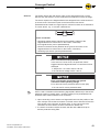
CAUTION
Unintended start-up of the RollerDrive following
cooling down of the SegmentControl/ComControl
Danger of crushing of limbs and damage to goods
Ensure that no start signal is pending during the
cooling-down process.
Interfaces to other systems
With the help of the inputs on the ComControl, signals from upstream systems
can be used and further processed (see "Possible wiring of the inputs", page 70),
e. g., an external signal can be evaluated as a start signal for the first zone.
Equally, signals from the last zone (e. g., the zone status) can be output via the
outputs of the ComControl in order to make them available to downstream
systems (see "Possible wiring of the ComControl outputs", page 80).
12
Version 2.0 (04/2013) en
Translation of the original instructions
ConveyorControl
Product information
Time-outs
Time-out when leaving the
zone sensor (TimeOut1)
The following delays and time-outs can be used:
With this time-out it can be monitored whether packages are jammed and thus
can no longer be transported.
After starting transportation of a package, the blocked zone sensor must become
unblocked after the specified period of time (can be set using parameter PZ6). If
the sensor is still blocked at the end of this time period, TimeOut1 occurs.
Parameter PZ7 can be used to set whether the conveying mode is to be stopped
in this case. If the parameter PZ 7 = Ignore error, the RollerDrive will continue to
rotate until the sensor becomes unblocked and the subsequent switch-off delay
time has expired.
The error can be reset by pushing the package manually into the detection area
of the zone sensor in the downstream zone. After resetting, the subsequent zone
runs a local initialization.
Time-out when reaching the
zone sensor (TimeOut2)
With this time-out it can be monitored whether packages have been removed
manually or have fallen out. As soon as a package has left the detection area of a
zone sensor, the time required until it reaches the next zone sensor is measured.
If this is longer than the specified time (can be set using parameter PZ8),
TimeOut2 occurs. Parameter PZ9 can be used to set whether the conveying
mode is to be stopped or continued in this case. With the setting PZ9 = Ignore
error, the RollerDrive continues to rotate until another package blocks the zone
sensor.
The error can be reset by blocking the zone sensor in question.
RollerDrive run-on time
(AfterRunTime)
Once a package has left the sensor of a zone, then the RollerDrive in this zone
continues to rotate for up to 10 seconds (can be set using parameter PZ10). At
the end of this period, the RollerDrive stops, providing no new package is
transferred from the upstream zone.
This feature provides the following benefits:
• Avoidance of unnecessary start/stop operation if there are no gaps between
the packages.
• Energy-savings by switching off the RollerDrive if no further packages have to
be transported.
Removing a package from the
detection area of the zone
sensor (PermissionDelay)
Version 2.0 (04/2013) en
Translation of the original instructions
If the zone sensor becomes unblocked following a manual intervention (pulling
back or removal of a package which has already stopped), the RollerDrive
continues to rotate this zone for up to 10 seconds (can be set using parameter
PZ11) in order to transport the package in the detection area of the zone sensor
again. During this time a signal is not sent to the upstream zone stating that the
zone is unblocked. This is to prevent an other package from moving in the zone.
If the sensor is not reblocked during this time, a unblocked message is sent to the
upstream zone.
13
ConveyorControl
Product information
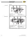
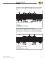
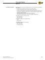
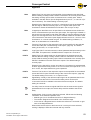
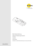
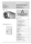
Structure
CentralControl
1
2
3
4
Mounting holes
Power supply connection
Label
USB connection
5
6
7
LEDs
Marker (changeable)
Bus communication connection
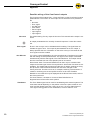
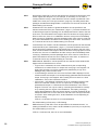
1
2
3
4
5
6
Left zone zone sensor connection
Left zone RollerDrive connection
Mounting holes
Power supply connection
Label
Right zone RollerDrive connection
7
8
9
bl
bm
Right zone zone sensor connection
LEDs
Marker (changeable)
Bus communication connection
Contact point for addressing
magnet
SegmentControl
14
Version 2.0 (04/2013) en
Translation of the original instructions
ConveyorControl
Product information
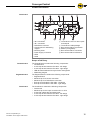
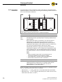
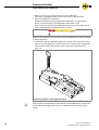
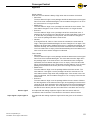
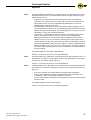
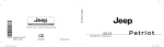
ComControl
14
1
2
3
4
5
6
7
8
IN 2 connection
IN 1 connection
RollerDrive connector
Contact point for addressing
magnet
Mounting holes
Power supply connection
LEDs
Label
9
bl
bm
bn
bo
bp
Terminal box cover for other inputs
and outputs
Terminal box cable passage
Bus communication right branch
Marker (changeable)
Bus communication connection
Bus communication left branch
Scope of delivery
CentralControl
SegmentControl
ComControl
Version 2.0 (04/2013) en
Translation of the original instructions
The CentralControl contains the following components:
• CentralControl
• 2 end caps to terminate the flat cable - left design
• 2 end caps to terminate the flat cable - right design
• USB stick with software ConveyorControl Configurator
• Addressing magnet
The SegmentControl contains the following components:
• SegmentControl
• M8 blind cap for a sensor connection
• M8 blind cap for a RollerDrive connection
• End cap to terminate the flat cable - left design
• End cap to terminate the flat cable - right design
The ComControl contains the following components:
• ComControl
• M8 blind cap for the input connection IN 1 or IN 2
• 2 short flat cables with two sealed ends
• 3 end caps to terminate the flat cable - left design
• 3 end caps to terminate the flat cable - right design
15
ConveyorControl
Product information
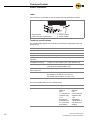
Label
The information on the label is used to identify the ConveyorControl module.
1
2
Manufacturer
Week and year of production
3
4
Article number
Serial number
Technical specifications
The following data applies to all modules (CentralControl, SegmentControl and
ComControl):
Rated voltage
24 V DC
Voltage range
19 to 26 V DC
Protection classification
IP54
Weight
approx. 370 g
Ambient temperature in
operation
-28°C to +40°C (-18 °F to +104 °F)
Temperature change
1 K/min, 3 h (two cycles in acc. with IEC 68-2-14)
Air humidity
max. 93% at 40°C (104 °F), 14 day, non-condensing
(IEC 68-2-78, DIN EN 60068-2-78)
Installation height
above sea level
max. 1000 m (max. 3300 ft)
Mechanical stress
IEC 60068-2-27 15 g / 6 ms; 10 g / 11 ms
EC 60068-2-6 2-500 Hz ±1.6 mm / 2 g
IEC 60068-2-64 2-500 Hz ±1.6 mm / 2 g
The following data differs for the modules listed:
Current consumption
16
CentralControl
SegmentControl
ComControl
100 mA
approx. 6 A
effective
max.:
11 A at 500 ms,
repetition rate
1 Hz
Assumption:
2 RollerDrives
are connected
and rotating
approx. 3 A
effective
max.:
5.5 A at 500 ms,
repetition rate
1 Hz
Assumption:
1 RollerDrive is
connected and
rotating
Version 2.0 (04/2013) en
Translation of the original instructions
ConveyorControl
Product information
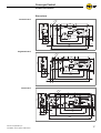
Dimensions
CentralControl
5
4,
54
70
Ø
8
82
10
27
120
158
9
9,7
8
175
SegmentControl
5
4,
70
54
Ø
8
82
10
27
120
158
9
8
175
9,2
ComControl
5
4,
70
54
Ø
9,2
8
82
10
120
27
34
158
8
5
200
Version 2.0 (04/2013) en
Translation of the original instructions
17
ConveyorControl
Transport and storage
Ambient conditions for transport and storage
Permissible ambient
temperature
-40 °C to +85 °C (-40 °F to 185 °F)
Permissible relative
humidity
max. 93% @ 40°C (104 °F), 14 day, non-condensing
(IEC 68-2-78, DIN EN 60068-2-78)
Temperature change
1 K/min, 3 h (two cycles in acc. with IEC 68-2-14)
Transport
•
Every ConveyorControl system module is packaged in its own cardboard box.
There is a risk of damage to property if transported
incorrectly
Only qualified and authorized persons should transport
the product.
Follow the instructions below.
Do not stack more than four cardboard boxes on top of each other.
Check that the boxes are correctly fixed in place prior to transport.
Avoid serious impacts during transport.
Check every ConveyorControl system module for visible damage after
transport.
In the event of damage, take photos of the damaged parts.
To maintain the warranty, report any damage caused by transport instantly to
the transport company and Interroll.
Do not expose the ConveyorControl system modules to large temperature
fluctuations as this could result in condensation.
Storage
Risk of damage to property due to improper storage
Do not stack more than four cardboard boxes on top of
each other.
Inspect each ConveyorControl module for damage after storage.
18
Version 2.0 (04/2013) en
Translation of the original instructions
ConveyorControl
Planning
The conveyor can be virtually planned in advance using the ConveyorControl
Configurators (referred to in the following as the Configurator). All the module
parameters can be set offline and then downloaded collectively to the real
conveyor.
General information
The Configurator has been developed for use together with the operating system
Microsoft Windows XP Professional, Version 2002, Service Pack 3.
The Configurator can be used in the languages English and German. Some
system-based information is always shown in the language used by the operating
system regardless of the language set. For some technical terms a translation
has not been provided in order to aid an understanding of the concept.
The Configurator does not realize any safety functions with respect to personal
protection, protection of the system and protection of the packages. The user is
responsible for ensuring that dangerous operating states can not arise.
Changes to the software, including reverse engineering, are not permitted.
Liability for any damage to the user or third parties resulting from the installation
and use of this software is ruled out.
Install software
The Configurator is included on an Interroll USB stick with every CentralControl
and every GatewayControl. The USB stick cannot be purchased separately. The
latest version of the Configurator can also be downloaded from
www.interroll.com.
Hint
On connecting for the first time to a CentralControl supplied with operating
voltage, the driver of the relevant USB port is installed. To this end, administrator
rights are necessary.
Ensure that administrator rights are available on the computer.
Insert a USB stick into the computer.
If the autorun function is activated on the computer, installation starts
automatically.
If the autorun function is deactivated or if the software has been downloaded,
call up the setup.exe file.
Follow the instructions in the installation dialog.
Hint
The Configurator can be installed any number of times on any number of
computers.
Version 2.0 (04/2013) en
Translation of the original instructions
19
ConveyorControl
Planning
Basics
With the help of the Configurator, a conveyor with a maximum of 100
ConveyorControl modules can be planned, addressed and parameterized. The
maximum permitted total length of bus communication is 200 m.
Within the Configurator the conveyor is designated as a project. Any number of
projects can be created and, as such, any number of conveyors can be planned.
Only one conveyor can be planned for each project. Planning comprises five
steps. These steps are shown by gray arrows in the upper section. The selected
step is shown in yellow.
The construction of the conveyor, preparation of addressing and the
parameterization of the modules can be carried out without a connection to a
specific conveyor. This helps to reduce the time needed for commissioning.
There must be a USB connection to the conveyor in order to address and
download the parameters to the modules.
A conveyor must comprise several ConveyorControl modules. Each of these
modules can be parameterized individually. All parameter values have upper and
lower limits; some values are subject to a plausibility check. If decimals are
entered as parameter values, in the German language setting a decimal comma
must e used, in the English language setting a decimal point must be used.
Hint
Addresses and parameters can only be downloaded from the computer to the
ConveyorControl system; however they cannot be read out again. As such, the
downloaded data should be saved in a project file which can be clearly assigned
to the conveyor for possible subsequent changes. If an existing system is to be
changed, this file can be used and changed accordingly. If this file is not
available, the complete conveyor must be remapped, addressed and
parameterized.
Operating instructions
Operation of the Configurator is based on the usual functionalities for graphical
user interfaces. Elements can be selected by a mouse click or via a pull-down
selection. Several elements can be selected if they are clicked on whilst the
CTRL button is held down. All elements are selected with the key combination
CTRL + A. Selected elements are shown in yellow.
Fields which cannot be changed are shown in light gray. Buttons which cannot be
used are either blended out or shown in light gray.
Operating and function errors are shown via screen messages. Work with the
Configurator can only continue once the cause of the error has been remedied
and the logical order of the operating steps has been adhered to or once all input
conditions have been satisfied.
The size of the elements on the working area can be changed with the zoom by
moving the mouse wheel whilst the CTRL button is held down.
20
Version 2.0 (04/2013) en
Translation of the original instructions
ConveyorControl
Planning
Definitions of terms
•
•
•
•
•
•
Version 2.0 (04/2013) en
Translation of the original instructions
Zone: The conveyor line is divided into zones. The zone length is based on
the length of the longest package. One zone consists of a RollerDrive, several
idler rollers, a control and a zone sensor (see "Zero pressure accumulation
conveying", page 10). In the Configurator a zone is symbolized as a gray
square (see "Constructing the conveyor line", page 26).
Slave RollerDrive: For some applications the use of an additional RollerDrive
per zone is necessary. With the ConveyorControl it is possible to connect a
second RollerDrive (Slave RollerDrive) to a SegmentControl. This is only
possible if the SegmentControl has only been assigned to one zone within the
Configurator. The SegmentControl to which the Slave RollerDrive is
connected can be selected with parameter PZ4. The Slave RollerDrive
properties can be set separately, it is, however, recommended to specify the
same values for the parameters of the zone's Slave RollerDrive and regular
RollerDrive. The error reaction of a Slave RollerDrive follows the regular
RollerDrive of the zone. An error is displayed both on the module to which the
Slave RollerDrive is connected and on the module which controls the Slave
RollerDrive.
Module: Component of ConveyorControl (ComControl, SegmentControl,
CentralControl or GatewayControl)
Conveyor line: A conveyor line comprises any number of zones (max. 197)
which are connected to each other. There is only one start and end zone.
Conveyor: A conveyor comprises several conveyor lines. As such there are
several start and end zones. In terms of the release modes, the conveyor
lines work independently. Global signals, e.g., Clear or Conveyor direction
switch always relate to the entire conveyor.
Power reset: Turns off the power supply for the entire conveyor and then
turns it on again (after a minimum of 3 seconds). If a conveyor is supplied by
several power supply units, all power supply units must be switched on within
a maximum of 10 seconds.
21
ConveyorControl
Planning
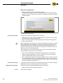
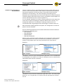
Start the Configurator
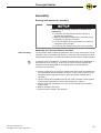
Start the ConveyorControl Configurator program.
The start screen appears in which a yellow progress bar shows the loading
progress. Once the Configurator has been fully loaded, the following selection
window appears:
Select the desired option.
Create a new project
A new project should be created for every conveyor.
Enter the project name. Ideally a name should be used which can be clearly
assigned to the conveyor at a later date.
Click on the button behind the Storage path field to select the storage path.
Click on the OK button.
Hint
When creating/opening a project file, a temporary hidden lock file with the name
"lock.projektname.xml" is created. This serves to prevent the project file being
opened by several users simultaneously and to also automatically save the
project content every two minutes. When the project file is closed correctly, the
temporary file is automatically deleted.
If the Configurator is not closed correctly, the lock file is not deleted and thus
further editing of the project file is not possible.
If the changes made before terminating the program are not to be saved,
delete the "lock.projektname.xml" file. If the file is not shown, activate the
option to display hidden files in the file manager.
If the changes made before terminating the program are to be saved, rename
the "lock.projektname.xml" file to "projektname.xml". If the file is not shown,
activate the option to display hidden files in the file manager. If necessary also
rename or delete the old project file.
Load the last project
Load the current project
This project opens the project which was last edited. This is the data on mapping,
address planning as well as the parameters as last edited.
This option opens the Windows dialog window to select files.
Search for and select the desired project file.
Close
22
Closes the Configurator.
Version 2.0 (04/2013) en
Translation of the original instructions
ConveyorControl
Planning
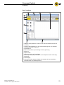
User interface
1
2
3
4
5
6
7
8
9
bl
bm
Version 2.0 (04/2013) en
Translation of the original instructions
Statistics field (shows the number of the used and selected zones and
modules)
Function area (depending on the activated working step, the available
elements/functions are shown)
Work step bar
Button bar (buttons for processing the zone geometry)
Menu bar
Project name
Name and version of the software
Work step description (information on the respective active work step)
Work area
Zoom display
Connection status (shows whether the computer is connected with a
CentralControl or a GatewayControl)
23
ConveyorControl
Planning
Menu bar
The functions in the File menu are typical for Windows (New, Open, Save, Save
as, Exit). In addition the zone designations can be exported here.
In the View menu the following functions are available:
• Language: Upon installation English is set, each time the program is called
up, the language last used is set.
• Show Zone corner points: The marking points are shown at the zone corner
points. *
• Show Zone dock points: Circles are displayed at the possible dock points of
the zone symbols as "catch" points. *
• Zones show Node ID / Zones show user zone designation: Switching between
visualization of the actual zone address and the zone designation assigned by
the user. The zone designation is shown as standard, the Node ID is only
used for internal diagnosis purposes.
* graphic visualization see "Constructing the conveyor line", page 26
USB connection status
This symbol shows whether the computer is connected with a CentralControl or a
GatewayControl)
Connected
24
Disconnected
Version 2.0 (04/2013) en
Translation of the original instructions
ConveyorControl
Planning
Functional concept
The Configurator is divided into five steps which are based on the order of work
when configuring a conveyor:
• Construct (see page 26)
• Prepare to Address (see page 30)
• Address (see page 53)
• Parameterize (see page 32)
• Download (see page 57)
The individual steps can be selected by clicking on the relevant buttons or by
clicking on the Next button. Deviations from the specified order of processing are
possible. For example, the steps Construct, Prepare to Address and
Parameterize can be performed in preparation without the computer being
connected to a conveyor. When this connection is subsequently created, only the
steps Address and Download have to be performed.
Construct
In the Construct step, the conveyor must be recreated from the individual zones
and modules in a graphic interface. The length of the zones can be changed at
will and/or bent, this allows a good likeness of the actual conveyor to be created.
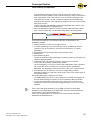
Preparing to Address
For intercommunication of the modules, each module must have an unambiguous
address. The addressing order is specified in this step.
Address
The modules are addressed in this step. As, for this, the computer has to be
connected with the conveyor, this step is described in the chapter on
"Commissioning" (see page 53).
Parameterize
Parameters must be assigned to each module. All parameters are set with
recommended standard values. For the system to function, the following
parameters must be adjusted as a minimum: RollerDrive speed, gear ratio and
direction of rotation, sensor switching and assignment of the inputs on the
ComControl.
Download
Once all parameters are set, the settings must be downloaded to the modules.
As, for this, the computer has to be connected with the conveyor, this step is
described in the chapter on "Commissioning" (see page 57).
Version 2.0 (04/2013) en
Translation of the original instructions
25
ConveyorControl
Planning
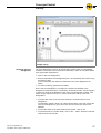
Constructing the conveyor line
In this step, the conveyor line must be constructed in the Configurator. To this
end, virtual zones with various conveyor directions (to the right, to the left,
upward, downward) and ConveyorControl modules are available.
A zone is shown as a square in the Configurator:
Visualization of a zone in the function area (left) and in the work area
(right)
The arrow shows the conveyor direction. The red and green circles are catch
points with which several zones can be connected. The blue dots show the
corner points. The catch and corner points can be hidden (see "Menu bar",
page 24). The number is the zone designation (the last three digits of the zone
designation are always shown).
A zone always contains at least one RollerDrive and a zone sensor which,
however, is not shown separately. Zones which have been selected are
highlighted in yellow.
Positioning zones
Drag a zone from the function area to the work area with the mouse button
held down.
To change the shape of the zone click on one of the zone's catch points and
drag on this with the mouse button held down. Reshaping can be restricted
using the button bar as follows:
Zone can be freely shaped
Shaping with a constant angle of curvature
Shaping with a constant radius
Shaping with a constant length
To change the angle of curvature in a controlled manner, click on the zone
with the mouse wheel.
This causes the zone to be curved by 15° with each click.
Attach further zones in the same way.
To connect two zones, merge their catch points.
The zones are docked together.
Hint
Zones which are to be connected, must have the same conveyor direction. Only
zones which have been docked together are functionally connected.
To release docked zones, move these quickly with the mouse wheel held
down. Slow dragging does not result in separation in order to avoid accidental
break-up of a zone connection.
To delete one or several zones, mark these and press the DEL button or click
on the marked zone with the right mouse button and select Delete object.
26
Version 2.0 (04/2013) en
Translation of the original instructions
ConveyorControl
Planning
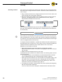
Example set-up
Changing the zone
designation
The zone designation is shown as a three-digit number which is automatically
increased. The zones can be renamed if necessary in order to use personalized
more appropriate designations.
Click on the zone designation.
Enter an alternative zone designation (max. 16 characters) and confirm using
the Return button.
In the Configurator the last three characters of the zone designation are
shown.
To cancel renaming, press the Esc button.
Even if the zone designation is changed, the actual zone address in the
background remains the same. If necessary, an allocation matrix can be exported
in which the actual zone address for each user zone designation is listed. This
matrix can be exported in a PLC in order to work there with the user zone
designations.
To export the matrix in the File menu select the command Export zone
designation....
The allocation matrix is shown as a dual-column table. In the first column the
user zone designation is given and in the second column the actual zone
address.
To save the matrix in the same folder as the project, click on OK.
To save the matrix in another folder, click on the ... button, select the relevant
folder and confirm with OK.
Version 2.0 (04/2013) en
Translation of the original instructions
27
ConveyorControl
Planning
Allocating modules
Once all the zone symbols are placed on the work area, they must be allocated
the ComControl or SegmentControl modules. Allocation must be identical to the
real conveyor.
Drag a module (ComControl or SegmentControl) from the function area to the
work area with the mouse button held down.
Drag the module at the middle of the long side of a zone in order to link it to
this zone. If a SegmentControl is to be linked with two zones, drag the
SegmentControl between the two zones.
The connection is symbolized by a line on the long side of the zone. This line is
the color of the respective module (light blue for SegmentControl and dark blue
for ComControl).
Hint
The module can be allocated to the right or left side of the zone, but not to both
sides simultaneously. The side on which the module is positioned is designated
by a blue line. This must reflect the actual situation as otherwise the left and right
zone of a SegmentControl are mixed up.
To simplify electrical installation, if possible all modules should be positioned on
the same side of the conveyor line. In the case of curves, wherever possible the
modules should be positioned on the outside radius of the curve as the
RollerDrive is connected on this side.
Ensure that all zones on the work area are connected to a module.
Zones and modules without a connection are highlighted red when moving to
the next step.
Delete zones and modules which are not used.
If modules have to be positioned on different sides, the following points must be
taken into account:
• The rotating direction of the RollerDrive must be parameterized correctly if
this is installed differently (see "Parameterizing modules", page 32).
• When laying the flat cable for bus communication and the power supply, more
flat cable is used on the other side (see "Changing the side of assembly",
page 44). This must be taken into account during planning in order not to
exceed the maximum permissible length (200 m).
To release the connection, mark the blue line (it turns yellow) and drag away
with the mouse button held down.
A zone can also be moved, reshaped or deleted with the allocated module.
28
Version 2.0 (04/2013) en
Translation of the original instructions
ConveyorControl
Planning
Allocate CentralControl or
GatewayControl to the
conveyor
A CentralControl or GatewayControl is required for each conveyor. This,
however, is not linked with a zone in the Configurator.
Drag a CentralControl or GatewayControl from the function area to the work
area with the mouse button held down.
It can be positioned at any location on the work area. To ensure clarity, it is
advised to position it at the point where the real conveyor is assembled.
Above all, this facilitates checks where a bus termination has already been
implemented via the CentralControl . It can thus be detected that a
ComControl must be positioned at the other end of the bus line.
Hint
If there is no CentralControl or GatewayControl available on the work area, an
error message appears when moving to the Address step.
It can only ever be assigned to a CentralControl or GatewayControl of the
conveyor. If a wrong selection is made, the wrong module must firstly be deleted
in the work area before it can be replaced with the right one.
Zones with assigned modules
When checking, the following points must be considered:
•
•
Version 2.0 (04/2013) en
Translation of the original instructions
A bus line needs a start and an end. The start and end must not be connected
to each other.
The conveyor must have a defined start and end zone in the Construct step.
That means there must be a point at which two zones are not connected to
each other.
29
ConveyorControl
Planning
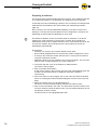
Preparing to Address
For functioning bus communication within the conveyor, every module must have
an unambiguous address. The addresses are assigned by the Configurator.
In this step, the order of addressing is planned. It is not until the next step that the
addresses are downloaded to the real modules (see "Addressing modules",
page 53).
Every conveyor line must be addressed separately. If several conveyor lines
belong to a conveyor and are thus planned in the Configurator in a project, the
addressing must be prepared individually for each route.
Hint
The difference between a zone and module must be observed. In the above
example, the route comprises 12 zones and 7 modules. Only modules are
addressed and not zones. A SegmentControl can be connected to two zones, but
only has one address. By connecting the zone and module, the zones are
automatically also detected.
Prerequisites:
• All zones in a conveyor line must be docked to each other.
• Every module (SegmentControl or ComControl) must be assigned to a zone.
• A conveyor line must have a start and end zone. A conveyor line must thus
comprise at least two modules.
• Addressing planning is only possible in the conveyor direction. The end zone
must be in the conveyor direction vis-à-vis the start zone.
In the work step bar, click on the Prepare to Address button.
The function area changes.
Click on the New Route button.
A new route is shown in the route list. The new route is automatically given the
number 0 and the name Route 0. Additional routes are numbered
consecutively.
If the route name is to be changed, click on the name and enter the desired
name. An unambiguous name facilitates assignment of the route in the next
steps.
Select the module which is to be addressed first.
The zone's conveyor direction display changes from white to black.
Click on the end module in the route. The end module must be located in the
conveyor direction behind the start module. The end module selection can be
changed any number of times.
The entire route is now highlighted light brown.
30
Version 2.0 (04/2013) en
Translation of the original instructions
ConveyorControl
Planning
Click on the Route Done button.
The route is now completely defined and is highlighted green. In the route list
a green point appears next to the name.
If the addressing is to be changed, mark the route in the route list, click on the
Delete Route button and recreate the route as described above.
Hint
The button Print Route is only available if a route is concluded and is selected in
the route list. Printing a route can, with complex conveyors, provide a better
overview and thus facilitate addressing.
Hint
With long conveyor lines it may prove recommended to address the routes in
several sections. As in the case of addressing errors (e. g., wrong order), the
complete route has to be readdressed, this can reduce the time required in the
event of errors.
The downloading of addresses to the modules is described in the chapter
Commissioning (see "Addressing modules", page 53).
Version 2.0 (04/2013) en
Translation of the original instructions
31
ConveyorControl
Planning
Parameterizing modules
Given the numerous possible applications of the ConveyorControl the individual
modules have to be parameterized to determine which functions the conveyor
has to perform.
In this step the settings for the various parameters can be determined. They only
become effective once they have been downloaded to the modules (see
"Downloading parameters", page 57).
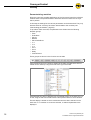
To provide a better overview, the parameters are divided into the following
thematic groups:
• Zone
• RollerDrive
• Sensor
• Module
• Slave RollerDrive
• In 1
• In 2
• In 3
• Out 1
• Out 2
• Relay
• CentralControl
These groups are shown in the function area as tabs.
If the function area is too narrow to display all the tabs, the tabs which are not
visible can be called up using the arrow to the right of the tabs.
Individual tabs can also be dragged onto a separate window in the work area. To
do this, drag the tab with the left mouse button pressed down to where desired.
The tab display is based on which modules/zones have been selected on the
work area. If no modules or zones are selected, no tabs and parameters are
displayed.
32
Version 2.0 (04/2013) en
Translation of the original instructions
ConveyorControl
Planning
Limitation and plausibility of
the parameters
There are selection lists for most parameters from which preset values can be
chosen. For the other parameters a value must be entered which lies between
the specified maximum and minimum limits. These limits ensure that each
parameter is set expediently. The rational interplay of the settings of all
parameters is the responsibility of the user as this depends on diverse framework
conditions (specific dimensions of the conveyor, properties of the packages, the
sensors and RollerDrives used, interface signals etc.).
It is, for example, possible to set a slow conveying speed and, at the same time,
a short time-out (time the package is allowed to take to leave a sensor). The
Configurator allows such a combination of settings, however this is not
recommended with long packages as this would trigger a release mode error.
Hint
Enter the desired resulting speed as the speed. The Configurator converts the
speed to various diameters.
Only the following parameters from the tabs RollerDrive and Slave RollerDrive
are subject to a plausibility test:
• PD1 GearRatio
• PD2 RDDiameter
• PD4 MainSpeed
• PD5 AlternativeSpeed
When a value is entered for these parameters, the Configurator checks whether
this is appropriate for the values of the other three parameters. If this value is
outside of the possible range, the value jumps back to the value last set.
Example 1:
Initial situation
Attempted entry
The speed 1.4 m/s can only be achieved with a gear ratio of 12:1 if the diameter
of the RollerDrive is at least 54 mm. Entry of a diameter of 50 mm means that the
last entered value of 60 mm is retained.
Example 2:
Initial situation
Attempted entry
The speed 0.5 m/s cannot be entered with a gear ratio of 64:1. The value jumps
back to 0.1 m/s. The gear ratio 16:1 must be set, then the speed can be set to
0.5 m/s.
Version 2.0 (04/2013) en
Translation of the original instructions
33
ConveyorControl
Planning
Setting parameters
Prerequisites for setting the parameters:
• The route has been completely mapped in the Configurator (see "Constructing
the conveyor line", page 26).
• The following information is available:
– Position and switching properties of the zone sensors
– Arrangement of the modules on the conveyor and the connection position
– Type of RollerDrives used (gear ratio, diameter, etc.)
– Kind of the packages (for possible delay times, speed setting, time-out
settings, acceleration/deceleration settings etc.)
– Information on all inputs and outputs and their electric parameters
– Further information, e.g., use of Slave RollerDrive
In the work step bar, click on the Parameterize button.
Select one or more modules and/or zones.
The set parameter values are assigned to the selected modules/zones. In
most cases it is recommended to select several modules/zones and then to
change the parameters.
Change the parameters according to the requirements. To this end, click on
the value of the parameter and then enter the desired value or select an entry
from the drop-down list.
If the parameter name is shown in gray, the value cannot be changed.
To reset all the parameters of the selected modules/zones to the factory
settings, click on the Reset Parameters button.
The factory default setting of the parameters corresponds to the functioning of
the Interroll ZoneControl. When creating a new project all parameters must be
checked and, if necessary, adapted.
The following parameters must be set as a minimum:
• PIN1 LogicType (PNP or NPN): for all sensors connected to the
SegmentControl and ComControl
• PIN2 SwitchType (normally closed / normally open): for all sensors connected
to the SegmentControl and ComControl
• PIN4 Function: for all ComControls it must be selected to which input (In1, In2
or In3) the zone sensor is connected
The parameters are saved in the Configurator on saving the project. Parameter
sets with which a conveyor works well should be saved for possible later changes
as the parameters cannot be read by at the modules following downloading to the
latter.
Hint
The parameters only become effective once they have been transferred to the
modules (see "Downloading parameters", page 57).
The Reset Parameters button only effects the previously selected modules.
34
Version 2.0 (04/2013) en
Translation of the original instructions
ConveyorControl
Planning
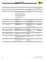
Overview of parameters
Below the setting options of the individual parameters are shown in the order of
the tabs.
A detailed explanation of the parameters is given in the appendix (see "Glossary
of parameters", page 82).
Zone
This tab includes the information on the numbering of the previous and
subsequent zone, the release mode selection, the setting of all time parameters,
the setting of error reactions and the selection of the number of a
SegmentControl to which a second RollerDrive (Slave RollerDrive) can be
connected.
ID
Name
Meaning
Value range
Default
setting
PZ2
UpStreamAdr
Address of the upstream zone
Cannot be set
–
PZ3
DownStreamAdr
Address of the downstream
zone
Cannot be set
–
PZ4
AdrSlaveRD
Address of the zone of the
assigned Slave RollerDrive
No Slave RD
No Slave RD
PZ5
ReleaseMode
Release mode
Single release
Train release
Single
release
PZ6
TimeOut1
Time from start of the
RollerDrive until the sensor
becomes unblocked
1 – 15 s in 0.1 s increments
0 = no time-out
5
PZ7
TimeOut1Reaction
Reaction when TimeOut1 is
exceeded
Ignore error
Zone stop + LED flashing
Zone stop +
LED flashing
PZ8
TimeOut2
Time from when the sensor in
the upstream zone becomes
unblocked until own sensor is
blocked
1 – 15 s in 0.1 s increments
0 = no time-out
5
PZ9
TimeOut2Reaction
Reaction when TimeOut2 is
exceeded
Ignore error
Zone stop + LED flashing
Zone idle
Zone idle
PZ10
AfterRunTime
Time from when the sensor
becomes unblocked until the
RollerDrive stops if there are no
further packages
1 – 10 s in 0.1 s increments
0 = no after run
4
PZ11
PermissionDelay
Time between the following
statuses:
• Sensor blocked, zone in
status blocked (package
standing). Change to
unblocked status (sensor
unblocked) following
removal of the package
• Sensor unblocked,
"unblocked" message to
upstream zone
1 – 10 s in 0.1 s increments
0 = no after run
2
Version 2.0 (04/2013) en
Translation of the original instructions
35
ConveyorControl
Planning
ID
Name
Meaning
Value range
Default
setting
PZ12
TrainReleaseDelay
Delay in train release
0.1 – 2 s in 0.1 s increments
0 = no delay
0.2
PZ13
SensorDelay
Delay in sensor signal
(If the zone has to convey in
both directions, the sensor is
positioned in the middle of the
zone and the RollerDrive has to
run on for a specified time to
allow the package to be
transported to the end of the
conveyor zone.
0.1 – 2 s in 0.1 s increments
0 = no delay
0
PZ14
GlobalInitTime
Time period for global
initialization
1 – 10 s in 0.1 s increments
0 = no initialization
4
PZ15
LocalInitTime
Time period for local
initialization
1 – 10 s in 0.1 s increments
0 = no initialization
4
PZ16
RDErrorMode
Reaction in the event of a
RollerDrive error
Ignore error
LED flashing (RollerDrive is
still controlled)
Zone stop + LED flashing
Zone stop +
LED flashing
PZ17
RDErrorRecovery
Action after recovering a
RollerDrive error
No Init
Local Init
Local Init
PZ18
SensorErrorMode
Reaction in the event of sensor
low gain
Ignore error
LED flashing
Zone stop + LED flashing
Zone stop +
LED flashing
PZ19
SensorErrorRecovery
Action after recovering sensor
low gain
No Init
Local Init
No Init
PZ20
TemperatureRecovery
Action when the switch-on
temperature is reached after
the switch-off temperature has
been exceeded
No Init
Local Init
Power reset required
Power reset
required
PZ21
PowerErrorMode
Reaction in the event that the
power supply volatage is too
low or too high
Ignore error
LED flashing
System error
System error
36
Version 2.0 (04/2013) en
Translation of the original instructions
ConveyorControl
Planning
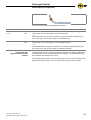
RollerDrive, Slave RollerDrive
This tab includes all the parameters for the functions of the RollerDrive. Since
parametrization of the gear ratio, diameter and conveying speed effects the
actual speed of the RollerDrive, plausibility is checked.
Every SegmentControl or ComControl can handle a RollerDrive and an additional
Slave RollerDrive. The Slave RollerDrive data can be set separately from the
main RollerDrive.
ID
Name
Meaning
Value range
Default
setting
PD1
GearRatio
Gear ratio
•
•
•
•
•
•
•
•
•
12:1
PD2
RDDiameter
Effective drive diameter
(enter the mean diameter for
conical RollerDrive)
50 – 80 mm
(no decimal points)
50
PD3
RDDirection
Direction of rotation on cable
side
Clockwise
Counterclockwise
Clockwise
PD4
MainSpeed
Speed of the RollerDrive
0.01 m/s –1.75 m/s
(max. 2 decimal places)
1.3
PD5
AlternativeSpeed
Alternative conveying speed
(can be controlled via a digital
input)
0.01 m/s –1.75 m/s
(max. 2 decimal places)
1.3
PD6
RDAcceleration
Acceleration
0 – 10.00 m/s2
(max. 2 decimal places)*
0 = no influence
0
PD7
RDDeceleration
Deceleration
0 – 10.00 m/s2
(max. 2 decimal places)*
0 = no influence
0
9:1
12:1
16:1
20:1
24:1
36:1
48:1
64:1
96:1
* The values which can be set are guidelines. Actual acceleration or deceleration
results from the RollerDrive and the value set. In principle, the RollerDrive
accelerates and decelerates as fast as possible. This can only be reduced with
the setting.
Version 2.0 (04/2013) en
Translation of the original instructions
37
ConveyorControl
Planning
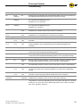
Sensor
This tab includes the parameters for the sensors on the SegmentControl. The
function is restricted to the connection of a zone sensor.
Hint
A SegmentControl can control two zones. Each zone can be parameterized
separately. When setting the parameters, it must be noted whether just one or
both zones of a SegmentControl were selected. The set parameters only apply to
the selected zone(s).
ID
Name
Meaning
Value range
Default
setting
PIN1
LogicType
Output type
NPN
PNP
PNP
PIN2
SwitchType
Switch type
Normally open
Normally closed
Normally
open
PIN3
LowgainInput
Low gain input
Without
With
Without
Module
ID
The parameters of the Modules tab must not be set, the parameters can merely
be read out.
Name
Meaning
Value range
Default
setting
NodeID
Numbering
Cannot be set
–
ProductKey
Article number of the module *
Cannot be set
–
Serial
Serial number of the module *
Cannot be set
–
* only displayed after addressing
38
Version 2.0 (04/2013) en
Translation of the original instructions
ConveyorControl
Planning
In 1, In 2 and In 3
This tab includes the parameters for the inputs of the ComControl. A zone sensor
must be connected to one of the inputs of the ComControl. The parameter
DigitalInputFunction must be set to the value "Zone Sensor" for the relevant
input. The tabs are assigned to the connections of the ComControl as follows:
Tab
Connection labeling ComControl
In 1
Zone Sensor
In 2
Add. Sensor
In 3
In/Out (terminal box)
ID
Name
Meaning
Value range
Default
setting
PIN1
LogicType
Output type
NPN
PNP
PNP
PIN2
SwitchType
Switch type
Normally open
Normally closed
Normally
open
PIN3
LowgainInput
Low gain input
(without in case of In 3)
Without
With
Without
PIN4
Function
Function assignment sensor
input*
(not available for
SegmentControl, function =
zone sensor)
Not used
Zone sensor
Start sensor
Start D one zone
Start Z one zone
Stop D one zone
Stop D all zones
Stop Z one zone
Stop Z all zones
Clear
Clear reverse
Alternative speed
Conveyor direction
Not used
* Only one input may be parametrized to the function Zone Sensor. The function
Start Sensor may only be connected to one input of the ComControl which
controls the first zone of a conveyor. If functions (e. g., Stop D all zones) are
defined at several inputs, these are linked with OR.
Version 2.0 (04/2013) en
Translation of the original instructions
39
ConveyorControl
Planning
Out 1, Out 2 and Relay
ID
Name
POUT1
This tab includes the parameters for the outputs of the ComControl in the
terminal box.
Meaning
Value range
Default
setting
LogicType
Output type
(only with Out 1 and Out 2)
PNP
(cannot be set)
PNP
POUT2
SwitchType
Switch type
Normally open
Normally closed
Normally
open
POUT3
Function
Function assignment
Not used
Error signal
Aux RD start*
Zone status
Sensor signal
Input signal 2
Input signal 3
Not used
POUT4
SignalDelay
Signal delay
1 – 10 s in 0.1 s increments
0 = no delay
0
* Output is switched parallel to RollerDrive.
CentralControl
The CentralControl must not be parameterized, the parameters can merely be
read out.
ID
Name
Meaning
Value range
Default
setting
PG1
ControlMode
Central or decentralized
conveyor control
Cannot be set
Decentralize
d
NodeID
Numbering
Cannot be set
–
ProductKey
Article number of the module
Cannot be set
–
Serial
Serial number of the module
Cannot be set
–
40
Version 2.0 (04/2013) en
Translation of the original instructions
ConveyorControl
Assembly
Warning information for assembly
Risk of damage leading to failure or shortened life
expectancy
Check each ConveyorControl module visually for
damage before assembly.
Make sure that these modules are not warped during
installation (no bending or torsion).
Do not drill additional mounting holes in the casing or
enlarge the holes provided.
Do not drop the modules to prevent internal damage.
Assembly of ConveyorControl modules
Initial assembly
The ConveyorControl modules are attached to the conveyor frame with 2 screws
(diameter 4 mm, not included with delivery). There are 3 mounting holes at each
module attachment point. The left-hand holes should be used for initial assembly.
Hint
To simplify electrical installation, if possible all modules should be assembled on
the same side of the conveyor. In the case of curves, wherever possible the
modules should be assembled on the outside radius as the RollerDrive
connection is on this side.
Identify a flat area on the conveyor system frame upon which the modules are
to be assembled. Ensure that there is approx. 40 mm space to the left of the
designated area in order to be able to move the module at a later date if
necessary.
Use the module as a template and mark the center of the left mounting holes.
For the distance between the holes, see "Dimensions", page 17.
Drill two holes with a diameter of 4.5 mm on the markings in the conveyor
system frame.
Bold the module to the frame.
Ensure that the housing is not distorted.
Version 2.0 (04/2013) en
Translation of the original instructions
41
ConveyorControl
Assembly
Repeated assembly
If an already connected flat cable had to be removed from a module,the flat cable
must not be pierced at the same point as otherwise a proper contact cannot be
ensured. To avoid the flat cable having to be removed and repositioned on all
modules, in this case the ConveyorControl module can be attached via the
central or right-hand mounting hole. Consequently, the position of the module to
the flat cable changes and the flat cable can be pierced at a different point. The
insulation is self-healing which means protection rating IP54 is achieved.
In the above picture, the module is attached via the left mounting hole, in the
below picture via the central mounting hole. The point at which the flat cable was
connected is marked with X.
42
Version 2.0 (04/2013) en
Translation of the original instructions
ConveyorControl
Assembly
Warning information relating to the electrical installation
Damage to ConveyorControl modules
Observe the following safety information.
Electrical work should only be performed by qualified and authorized persons.
Protection rating IP54 is only achieved with correct installation.
Disconnect the power supply before installing, removing or rewiring the
ConveyorControl modules.
Ensure that no hazardous voltage can come into contact with the connections
or the housing, not even in the event of a malfunction or fault.
ConveyorControl modules are never to be operated with AC current as this
will cause irreparable damage.
Do not use earth connections or earth wires as a protective conductor (PE).
Do not apply too much tension or load to the plug. The cable insulation can
become damaged if the cable is bent at the plug and the ConveyorControl
modules or the RollerDrive could fail.
Only use cables that are dimensioned sufficiently for the application.
Ensure that the switching power supply unit supplying the ConveyorControl
system supplies a nominal DC voltage of 24 V with a maximum deviation of
±8 %.
Ensure that the RollerDrive and the voltage source are connected to the
conveyor frame or supporting structure in such a way that they are properly
earthed. Incorrect earthing can result in the build-up of static charge, causing
the RollerDrive or the ConveyorControl modules to malfunction or fail
prematurely.
Use suitable switching equipment to ensure safe operation.
Only apply operating voltage when all of the cables have been connected.
Damage to the flat cable following incorrect wiring
Do not bend the flat cable on the narrow side.
When bending on the broad side ensure a minimum
bending radius of 12 mm (when in a fixed installation) or
30 mm (at moving points and during storage and
transportation).
When laying and when in a fixed installation ensure that
the flat cable is not subject to tensile stress.
Avoid excessive vibrations, unsupported free-hanging
cable, bending and crushing.
Version 2.0 (04/2013) en
Translation of the original instructions
43
ConveyorControl
Assembly
Electrical installation
Laying of the flat cables
Do not bundle the flat cable with other control cables or high-voltage lines.
Laying system C or E as per DIN VDE 0298-4 is favored.
Ensure that the bus line is not longer than a total of 200 m (including all
branches).
Do not connect any more branches to a line which branches off from the main
line. Branches may only lead off from the main line.
Cut off any residual length on the line ends; do not roll up.
Changing the side of
assembly
The laying of lines is simplest when all modules in the conveyor are assembled
on the same side. This, however, is not always possible, e.g., due to structural
obstacles (walls, pillars, etc.). Even if there are several curves in the route, it can
be recommended to change the assembly side as the connection of the
RollerDrive is always on the outside radius of the curve.
When changing the assembly side, the bus line coding must be observed, as
such there are three options when changing:
• Lay the main line in a loop on the other side.
• Lay the main line with a cable bridge on the other side.
• Branch off a line for the other side.
If a single module has to be repositioned to the other side, it makes sense to lay
the main line in a loop on the other side. The line must not be laid directly as
otherwise the polarity of bus communication would be reversed.
1
2
3
44
Conveyor
SegmentControl or ComControl
Obstacle (wall, column or similar)
Version 2.0 (04/2013) en
Translation of the original instructions
ConveyorControl
Assembly
If several modules have to repositioned to the other side, a loop has be laid for
each module. To keep the line has short as possible, in this case a cable bridge
can also be used. With the aid of the cable bridge, the bus line coding can be
adapted.
Changing the assembly side with cable bridges*
1
2
3
4
Conveyor
SegmentControl or ComControl
Cable bridge
Obstacle (wall, column or similar)
* The line to the power supply can be laid in the same way.
Alternatively one or several modules on the other side can also be connected
with a branched off line (connection 'Data A1' or 'Data A2'). In this case, however,
a ComControl has to be used with branching and at the end of each branched off
line.
4
1
2
3
4
Version 2.0 (04/2013) en
Translation of the original instructions
4
Conveyor
SegmentControl or ComControl
ComControl
Obstacle (wall, column or similar)
45
ConveyorControl
Assembly
Overview of connections
The ConveyorControl modules have the following connections:
Module
Connection
Signal/components
Contacting
Type
All
Power
Power supply
Flat cable via pin
IN
All
Data
Bus communication
Flat cable via pin
IN/OUT
CentralControl
USB
USB 2.0
USB Mini-B, 5-pin
IN/OUT
SegmentControl
RD left, RD right
RollerDrive
5-pin M8, snap in (suitable for
EC310)
OUT
SegmentControl
Sensor left,
Sensor right
Zone sensor
4-pin, socket M8
IN
ComControl
Data A1
Bus branch left
Flat cable via pin
IN/OUT
ComControl
Data A2
Bus branch right
Flat cable via pin
IN/OUT
ComControl
RD
RollerDrive
5-pin M8, snap in (suitable for
EC310)
OUT
ComControl
Zone Sensor
Input In 1
4-pin, socket M8
IN
ComControl
Add. Sensor
Input In 2
4-pin, socket M8
IN
ComControl
In/Out
(Terminal box)
Input In 3
Spring terminals
IN
Outputs Out 1, Out 2
Spring terminals
OUT
Relay: electrically isolated relay
contact
Spring terminals
OUT
The electrical parameters of the connections are specified in the appendix (see
page 89).
Lock time with bouncing level
To ensure functionality with a bouncing level, all signal inputs (In 1, In 2 and In 3)
are protected by firmware. This means that after a signal status change, there is
a lock time of 60 ms in which no additional status change is processed.
P
1
t
0
tx
1
2
3
46
Signal (with effect) and start of the lock time tx
Signals with no effect, as they lie within the lock time t x
The first signal that has an effect after the lock time tx
Version 2.0 (04/2013) en
Translation of the original instructions
ConveyorControl
Assembly
Power supply and bus
communication
A flat cable is used for both the power supply and bus communication, these
cables are fixed to the ConveyorControl modules using yellow tabs. Closing the
tabs pierces the cables.
Hint
If several PowerControl power supply units are used, the ground connections
must be connected to a common ground.
A PZ1 screwdriver is required for the screws of the tabs (Power and Data
connections) and the lid of the terminal box (see "Inputs and outputs
ComControl", page 50).
Ensure that all the necessary ConveyorControl modules are assembled onto
the conveyor.
Release the screws on the tabs and open the tabs.
Ensure that the flat cables for the power supply and for bus communication
are not mixed up:
– Power supply: Flat cable 2 x 2.5 mm², black
– Bus communication: Flat cable 2 x 1.5 mm², yellow
Lay the flat cable in the right direction (see graphic) without applying any load
or tension, if necessary take appropriate measures to reduce tension and
vibration. The tabs are positive-locking. As such, the flat cable can only be
laid in one direction and polarity cannot be reversed.
Note the orientation label on the side of the modules.
Place the flat cable straight on the ConveyorControl modules.
Press the flat cable onto the pin under the tab.
Close the tab and tighten the screw to max. 1.0 Nm.
In the case of the ComControl first bond the 'Data A1' or 'Data A2' connection
with side stream or blind cables in order to achieve protection rating IP54,
then bond the 'Data' connection. To improve cabling, press the Data flat cable
into the recesses on the 'Data A1' and 'Data A2' tabs.
Blind cable for sealing empty tabs to IP54
Version 2.0 (04/2013) en
Translation of the original instructions
47
ConveyorControl
Assembly
Hint
In the case of the ComControl the main bus communication line must always be
connected to 'Data'. Only one side stream may be connected to the 'Data A1' and
'Data A2' connections.
Only one side stream is permitted per ComControl. Thus a maximum of one of
the 'Data A1' and 'Data A2' connections may ever be used. Depending on the
desired position of the flat cable, either Data A1 or Data 2 is to be selected.
Activate the terminating resistor (dip switch in the terminal box) on the
ComControl at which the bus communication line ends.
If a flat cable ends at a module, secure a suitable end cap to the end of the flat
cable in order to achieve protection rating IP54.
Hint
If an tab had to be opened after bonding, the flat cable must not be reconnected
at the same point as otherwise a proper contact cannot be ensured. In this case,
the module must be repositioned (see "Repeated assembly", page 42).
RollerDrive
The connections 'RD left' and 'RD right' (on the SegmentControl) or 'RD' (on the
ComControl) are prepared for the RollerDrive EC310. The RollerDrive EC310
connection cable is already fitted with a suitable plug.
Insert the plug so that the module name (ComControl or SegmentControl) can
be read and that the labeling EC310 on the plug is to the rear, i.e. cannot be
read.
Upon connecting a RollerDrive to a SegmentControl note the position of the
RollerDrive: Always connect the left zone RollerDrive to 'RD left' and the right
zone RollerDrive to 'RD right'. If only one zone is to be controlled, the
RollerDrive must be connected to 'RD left'.
If two RollerDrive are to be connected in a zone, use a SegmentControl and
connect the Master RollerDrive to 'RD left' and the Slave RollerDrive to 'RD
right'.
If a RollerDrive connection remains unused, seal this with a M8 blind cap to
achieve protection rating IP54.
48
Version 2.0 (04/2013) en
Translation of the original instructions
ConveyorControl
Assembly
Sensors
The inputs 'Sensor left' and 'Sensor right' (on the SegmentControl) or 'Zone
Sensor' and 'Add. Sensor' (on the ComControl) are identical in terms of design.
The sensor inputs on the SegmentControl are designed for the zone sensors of
up to two zones. The sensor inputs on the ComControl can also be
parameterized and used as a signal input for various functions as an alternative
to a zone sensor, e.g., to connect a start sensor.
4
3
2
1
Sensor connection
1
2
3
4
Operating voltage sensor (identical to the operating voltage of the
SegmentControl or ComControl on the 'Power' connection)
Error signal sensor (can be parameterized)
Ground connection sensor (identical to the ground connection of the
SegmentControl or ComControl on the 'Power' connection)
Switching input sensor (can be parameterized)
Pin 1 is not short-circuit protected
In the event of a short-circuit, the protection fuse is
triggered and the SegmentControl or ComControl is thus
destroyed
Subject Pin 1 to a max. load of 100 mA.
Do not feed in voltage via Pin 1 and 3.
Pin 3 is electrically connected to the ground
connection of the operating voltage
Pin 3 does not have a protective earth function (PE)
Do not use Pin 3 as a protective earth.
Hint
At Pin 2 and 4 evaluation of the switching signal (PNP, NPN level) or the sensor
switching function (normally open / normally closed) can be parameterized as
desired to allow various sensors to be connected.
Upon connecting a zone sensor to a SegmentControl note the position of the
zone: Always connect the zone sensor in the left zone to 'Sensor left' and the
zone sensor in the right zone to 'Sensor right'. If only one zone is to be
controlled, the zone sensor must be connected to 'Sensor left'.
If a sensor connection remains unused, seal this with a M8 blind cap to
achieve protection rating IP54.
Version 2.0 (04/2013) en
Translation of the original instructions
49
ConveyorControl
Assembly
Inputs and outputs
ComControl
In the terminal box of the ComControl, there is the option of connecting further
inputs and outputs. The dip switch for turning the terminating resistor for the bus
line on and off is also located here.
+
+
ON
CAN
Term. a
b
OFF
GNG
Signal
Out 1
Out 2
Relay
In 3
+24V
1
2
Wiring diagram printed inside the lid
Dip switch and spring terminal block for inputs and outputs
Connection Description
Out 1
and
Out 2
Digital output. The use of the signal (e. g., as error output) and
the switching function (normally open or normally closed) can be
parameterized.
Both outputs are directly connected to +24 V DC and ground
without a fuse. In the event of an overload, the current is
automatically limited which, depending on the current, ambient
temperature and duration of the overload, results in a thermal cutoff. Once the overload has been reduced, the output
automatically switches on again (the ComControl must have
cooled down by approx. 15 K in relation to the temperature at the
time of switching off). This overload protection does not offer line
and load protection; it serves exclusively to protect the switching
level.
Note:
• When the switch is set to OFF, the terminals are not
electrically isolated from the operating voltage!
• The outputs Out 1 and Out 2 must not be interlinked.
• Power must not be fed in at Out 1 and Out 2.
Relay
Electrically isolated relay contact
In 3
Digital input signal. Evaluation of the signal (NPN or PNP) and the
switching function (normally open or normally closed) can be
parameterized. The purpose of the signal can also be
parameterized, e.g, as a start sensor.
All the connections in the terminal box are spring terminals for installation without
tools. The following conductors can be connected:
•
•
50
Braid wire 0.2 … 1.5 mm2, solid core or fine-wired without wire end sleeve
Braid wire 0.25 … 1.5 mm2 with wire end sleeve (in the case of the wire end
sleeve with collar max. 0.75 mm2)
Version 2.0 (04/2013) en
Translation of the original instructions
ConveyorControl
Assembly
Hint
The wire gauge must be selected according to the highest possible load current.
If loads are connected to the relay which are operated with more than safety
extra-low voltage, the necessary insulation spacing must be ensured.
The grommet (TPE) is specified for maximum 3 round cables Ø 4.5 … 6 mm. To
simplify attachment and creation of the holes, it can be removed from the
housing.
Strip 8 mm off the cables.
Guide the cables through the grommet and connect to the spring terminals.
For simpler operation, the white button can be depressed using a slot
screwdriver (blade width approx. 3 mm) and, in doing so, the terminal can be
enabled.
Ensure that the round cables used fit snuggly in the cable passages.
Close the lid of the terminal box so that it is flush with the housing and tighten
both screws to 0.8 Nm.
Hint
•
•
USB connection
CentralControl
Operation of the ComControl with an open terminal box lid or without grommet
is not permitted!
The grommet is not a cable relief. In accordance with the concrete operating
conditions of the specific conveyor, the cable/line types used and the electric
operating voltages of the connected components are required for safe
operation and/or additional module installation support.
The CentralControl features a USB mini B connection in order to connect it to a
laptop and to transfer the ConveyorControl Configurator data.
Pull off the protective black cap. Do not tear the mechanism against loss.
Connect the USB plug.
When the USB connection is no longer required, remove the USB cable and
reattach the protective cap to achieve protection rating IP54.
Ensuring protection rating
IP54
Depending on the use and thus the wiring of the ConveyorControl modules
connection options may remain open. To ensure protection rating IP54, these
connections must be sealed with protective caps.
Screw on M8 blind caps onto all unused sensor connections and RollerDrive
connections.
If a flat cable ends at a module, secure a suitable end cap to the end of the flat
cable.
If on the ComControl the connections 'Data A1' or 'Data A2' are not used, use
the blind cable parts enclosed to achieve protection rating IP54.
Close the lid of the terminal box of the ComControl so that it is flush with the
housing and tighten both screws to 0.8 Nm. Ensure that the round cables
used fit snuggly in the cable passages.
Ensure that the USB protective cap is attached properly on the
CentralControl.
Version 2.0 (04/2013) en
Translation of the original instructions
51
ConveyorControl
Assembly
CentralControl
ComControl
1
2
3
4
Direction of travel
PC
Power supply unit
Start sensor
SegmentControl
5
6
7
RollerDrive
RollerDrive
RollerDrive
=
RollerDrive
Example of connection
ComControl
Zone sensor
Flat cable power supply
Flat cable bus communication
An example of minimal wiring of the ConveyorControl for a conveyor with four
zones is shown. The example includes a CentralControl, two ComControls and a
SegmentControl as well as a power supply unit, a PC for addressing and
parameterizing, a start sensor and a zone sensor and RollerDrive per zone.
The SegmentControl controls and monitors two zones. The first ComControl
assesses the signal from a start sensor and controls a zone. The second
ComControl controls a zone and provides the terminating resistance for bus
communication. The modules are connected to each other via the flat cables for
the power supply and for bus communication. All the modules, sensors and
RollerDrive are supplied with operating voltage by the power supply unit.
The PC only has to be connected to the CentralControl during addressing and
parameterizing. During normal operation, connection of a PC is not necessary.
52
Version 2.0 (04/2013) en
Translation of the original instructions
ConveyorControl
Initial startup and operation
Initial startup
Checks before initial startup
Pre-commissioning checks
Ensure that all ConveyorControl modules have been correctly fastened to the
profile and that all screws have been correctly tightened.
Ensure that there are no additional areas of danger caused by interfaces to
other components.
Ensure that the wiring is in accordance with the specification and legal
directives.
Check all protection devices.
Ensure there are no bystanders in dangerous areas around the conveyor.
Check all ConveyorControl modules for visible damage.
Check all protection devices.
Ensure that no RollerDrive is blocked.
Clearly specify and monitor the way goods are placed on the conveyor.
Ensure there are no bystanders in dangerous areas around the conveyor.
Addressing modules
Each module must be given an unambiguous address before the conveyor can
be put into operation. The order of addressing was already planned in the step
Prepare to Address (see "Preparing to Address", page 30). On the basis of this
planning, each SegmentControl and ComControl must now be assigned an
address with the aid of the addressing magnet.
Prerequisites:
• All route in the conveyor were defined and concluded in the step Prepare to
Address.
• An addressing magnet is available.
Damage due to magnetism
Devices which are sensitive to magnets can be damaged
and data may be deleted.
Do not place the addressing magnet close to devices
which are sensitive to magnets or sensitive data
carriers (e. g., bank cards).
Using the USB cable connect the computer with the CentralControl or
GatewayControl.
The Configurator connection status is shown at the bottom left.
Connected
Disconnected
In the work step bar, click on the Address button.
If there is no connection to the CentralControl or GatewayControl an error
message to this effect is shown.
Version 2.0 (04/2013) en
Translation of the original instructions
53
ConveyorControl
Initial startup and operation
Mark the routes in the route list which are to be addressed.
The route is highlighted yellow in the route list and on the work area.
Click on the Address route button.
Whilst the modules are being prepared for addressing, a progress bar is
shown. The first module to be addressed is then shown in red.
On the conveyor only the 'Com' LED is illuminated on modules which do not
have a valid address, providing there are no errors.
Now the real modules (on the conveyor) must be assigned to the virtual modules
(in the Configurator).
To this end, hold the addressing magnet for at least 3 seconds (but no more
than 10 seconds) against the contact point of the module which corresponds
to the module marked red (position of the contact point see "Structure",
page 14).
Addressing magnet on the SegmentControl
Hint
If the modules are assembled in a steel profile, it is possible that the contact point
for the addressing magnet will not be in the position marked on the housing
surface.
54
Version 2.0 (04/2013) en
Translation of the original instructions
ConveyorControl
Initial startup and operation
If the addressing magnet is held correctly in front of the contact point, in
addition to the 'Com' LED the 'Fault-' LED also lights up. After one second the
'Com' LED flashes, after 3 seconds, the 'Com' and 'Fault'-LEDs flash. This
means that the module now has a temporary address and the addressing
magnet can be removed. If the addressing magnet is removed, all three LEDs
flash synchronously.
In the Configurator the addressed module is highlighted green and the next
module to be addressed is highlighted red.
When the addressing magnet is removed, all three LEDs flash at the same
time, if this is not the case, module addressing has not been successful.
A progress bar below the route list shows the ratio of addressed to nonaddressed modules.
Address all other conveyors in the same manner.
If module addressing is not successful, this can be repeated as often as
required, it may be necessary to check bus communication. To repeat
addressing:
End addressing in the Configurator using the button Close.
Reset power.
Start addressing again.
To reset an addressing during addressing, end the procedure in the same way
and start addressing again.
If addressing is to be ended prematurely, click on the Close button.
In this case, all temporary addresses are deleted.
Once all modules in a conveyor line have been addressed, and the progress
bar is complete, all the modules in this conveyor line are permanently
addressed. The addresses remain saved even in the event of power failure.
If an address is to be deleted on conclusion of addressing, hold the
addressing magnet for longer than 10 seconds in front of the contact point of
the relevant module.
Successful addressing is displayed as follows:
• The LEDs 'Ready' and 'Com' on the modules are constantly illuminated and
the LED 'Fault' displays a system error as no parameter data is available.
• A green dot appears behind the name of the route in the route list in the
Configurator. The route in the work area appears green once it is no longer
selected.
Hint
If the power fails during addressing or the USB connection is interrupted,
addressing must begin again as the addresses cannot be saved permanently
until the entire route has been addressed.
If there are several routes in a conveyor, each route must be individually
addressed as described above.
Version 2.0 (04/2013) en
Translation of the original instructions
55
ConveyorControl
Initial startup and operation
Addressing a replacement
module
If an already addressed route is to be addressed a second time, the addresses
are not overwritten. The Configurator checks the address of every module. Each
module is displayed in green when a valid address is available. The modules are
displayed in green step by step. If a module does not have a valid address, the
procedure on this module is stopped and the module can be addressed as
described above.
If a module is damaged, it has to be replaced.
Install a new module. Ensure that the flat cable contact is not in the same
place as before (see "Repeated assembly", page 42).
Switch on the power supply.
If the module is not brand new, hold the addressing magnet for more than
10 seconds in front of the contact point in order to delete any other
addressing.
Start addressing as described above.
The replaced module is shown in red in the Configurator, all modules in the
prior conveying direction are shown in green.
Hold the addressing magnet for at least 3 seconds and not more than
10 seconds in front of the contact point of the new module in order to address
it.
If necessary, address replaced modules in the same way.
56
Version 2.0 (04/2013) en
Translation of the original instructions
ConveyorControl
Initial startup and operation
Downloading parameters
The parameters which were set in the step Parameterize (see "Parameterizing
modules", page 32), must be downloaded to the conveyor in order to become
effective.
Prerequisites:
• All modules are addressed.
• All parameters are set in the Configurator.
• The computer is connected to the CentralControl or GatewayControl via the
USB line.
CAUTION
Collisions with external systems during parameter
downloading
Whilst downloading the parameters no packages should
be transported because output signals may not be
processed correctly.
In the work step bar, click on the Download button.
All parameters are downloaded. Depending on the number of modules, this
may take a few moments. A progress bar shows the status of the download
process.
If parameter downloading is started whilst the conveyor is operating, conveying is
stopped before the parameters are downloaded.
Following downloading of the parameters, the conveyor performs global
initialization automatically (see "Initialization", page 11) and then starts
conveying as per the parameters set. The computer can now be disconnected
from the CentralControl or GatewayControl.
Hint
The conveyor can only be stopped by a stop signal (e. g., via one of the
ComControl inputs) or by switching off the power supply.
If the parameters cannot be downloaded and saved in the modules, downloading
is ended and the 'Fault'-LED shows a system error.
Check bus communication in the case of a system error.
Reset the system error by resetting the power.
If the power fails whilst the parameters are being downloaded, the USB line is
interrupted or the Close button is clicked, downloading is ended and an error
message appears. The error message must be confirmed before the power to the
conveyor can be switched on again. There is no conveying or initialization for the
duration of the error message. If there were parameters in the modules prior to
downloading, these will be reactivated following discontinuation and confirmation
of the error message.
Hint
The Configurator project file with the set parameters should be saved and stored
in order to simply make changes at a later date. The parameters cannot be read
out of the modules again.
Version 2.0 (04/2013) en
Translation of the original instructions
57
ConveyorControl
Initial startup and operation
To delete all parameters in a module, hold the addressing magnet for more
than 10 seconds in front of the module's contact point.
The module is thus reset to factory default. It therefore also loses its address
and must be readdressed (see "Addressing modules", page 53) before
parameters can be downloaded again.
Hint
If the modules are assembled in a steel profile, it is possible that the contact point
for the addressing magnet will not be in the position marked on the housing
surface.
Self-test
The self-test allows the following functions to be checked before the flat cable for
bus communication is installed:
• Function and correct connection of the RollerDrive
• Function and correct connection of the zone sensors
• Function of and correct power supply to the respective module
During the self-test, the connected sensor and the RollerDrive are active. This
means that depending on whether a sensor is blocked or not, the respective
RollerDrive may or may not rotate. This interaction depends on the sensor's logic
type (normally closed or normally open). The 'Fault'-LED is continuously lit up,
the 'Ready' and 'Com' LEDs flash alternatively. The self-test take 10 seconds.
The self-test on a ComControl can only be performed as above if this has been
addressed and parameterized. If not addressed, the connected RollerDrive will
only change status if the zone sensor has been connected to IN1 and its status
changes.
Damage due to magnetism
Devices which are sensitive to magnets can be damaged
and data may be deleted.
Do not place the addressing magnet close to devices
which are sensitive to magnets or sensitive data
carriers (e. g., bank cards).
To trigger the self-test, hold the addressing magnet for at least one second
(but not longer than 3 seconds) in front of the module's contact point.
Hint
If the modules are assembled in a steel profile, it is possible that the contact point
for the addressing magnet will not be in the position marked on the housing
surface.
The self-test can also be triggered when the conveyor is operating. The
prerequisite for this is that the zone sensor is not blocked when the self-test is
triggered.
If the self-test is triggered whilst the conveyor is operating and the Configurator is
connected with the CentralControl or GatewayControl, the module for which the
self-test was started is circled in the Configurator (except in the Download step).
58
Version 2.0 (04/2013) en
Translation of the original instructions
ConveyorControl
Initial startup and operation
The result of the self-test is displayed by the LEDs:
LED Ready
LED Fault
LED Com
Meaning
Flashes
1 Hz
On
Flashes
1 Hz
Self-test activated, 1 sensor connected, 1 sensor unblocked (depending on the
sensor logic, this can also apply for a blocked sensor)
- or Self-test activated, 2 sensors connected, 2 sensors unblocked (depending on
the sensor logic, this can also apply for blocked sensors)
On
On
Flashes
1 Hz
Self-test activated, 1 sensor connected, 1 sensor blocked (depending on the
sensor logic, this can also apply for an unblocked sensor)
- or Self-test activated, 2 sensors connected, both sensors blocked (depending on
the sensor logic, this can also apply for unblocked sensors)
LED 'Ready' with
SegmentControl without
address
If a SegmentControl has not been assigned an address, the 'Ready' LED flashes
in the self-test if one or two RollerDrives are controlled. If both RollerDrives are
not controlled, the 'Ready' LED is lit up.
If the SegmentControl has only been allocated to one zone, only the 'Ready' LED
flashes as a second sensor is not connected and can thus not be blocked.
Version 2.0 (04/2013) en
Translation of the original instructions
59
ConveyorControl
Initial startup and operation
Operation
CAUTION
Accidental start-up of the RollerDrive
Danger of crushing of limbs and damage to goods
Ensure that no persons are in the conveyor's dangerous
areas before switching on the power supply.
Hint
If no RollerDrives in the conveyor rotate, this does not necessarily mean that the
conveyor is switched off.
Start
Ensure that the operating conditions are complied with during operation (see
"Technical specifications", page 16).
Switch on the power supply.
Once all modules are parameterized, the conveyor is initialized (see
"Initialization", page 11), conveying then commences.
Hint
If a conveyor is supplied by several power supply units, all power supply units
must be switched on within a maximum of 10 seconds. If this time is exceeded,
the CentralControl or GatewayControl displays a system error (see "Error
signaling", page 64).
Stop
60
Conveying stops in the following cases:
• If the power suppl is switched off.
• If a relevant signal is pending (see "Possible wiring of the inputs", page 70).
• If an error occurs.
Version 2.0 (04/2013) en
Translation of the original instructions
ConveyorControl
Maintenance and cleaning
Warnings concerning maintenance and cleaning
CAUTION
Risk of injury due to improper handling or accidental
motor starts
Maintenance work and cleaning may only be executed
by qualified and authorized persons.
Only perform maintenance work after switching off the
power. Ensure that the ConveyorControl system cannot
be turned on accidentally.
Set up signs indicating maintenance work.
Maintenance
Inspecting the
ConveyorControl
The ConveyorControl modules themselves are maintenance-free. For avoidance
of faults however, regular inspection of the connections and fixings is
recommended.
As part of the regular control and maintenance work on the conveyor, ensure
that the screws of all ConveyorControl modules are still tight and that the
cables are still laid properly and connected to the terminals.
Replacing ConveyorControl
modules
If a ConveyorControl module is damaged, it has to be replaced.
Install a new module (see "Shut-down", page 68 and see "Assembly of
ConveyorControl modules", page 41).
Address (see "Addressing a replacement module", page 56), parameterize
and download the parameters to the new module (see "Downloading
parameters", page 57).
Cleaning
Dust and dirt in combination with humidity may bridge the electric circuit.
Therefore, in a dirty environment, periodic cleaning will help to avoid shortcircuits which could damage the ConveyorControl modules.
CAUTION
Risk of damage to the ConveyorControl system
modules due to incorrect cleaning
Do not immerse the ConveyorControl system modules
in liquids.
Do not use cleaning agents.
Clean away dust and soiling if necessary.
For more thorough cleaning, disconnect the ConveyorControl system from the
power supply, remove the modules (see "Shut-down", page 68), and wipe
over with a damp cloth.
Version 2.0 (04/2013) en
Translation of the original instructions
61
ConveyorControl
Troubleshooting
Meaning of the LEDs
The LEDs provide information on the operating state of the ConveyorControl
system.
Each module has 3 LEDs:
• Ready (green)
• Fault (red)
• Com (green)
Hint
In the case of several faults, only the first fault which occurred is shown.
CentralControl
LED
Ready
LED Fault
LED Com
Meaning
Off
Off
Off
No operating voltage
Flashes
1 Hz
Off
Flashes
irregularly
Switching on of the operating voltage, network initialization
On
Off
Flashes
irregularly
Operating voltage present, network initialization successful, system in
operation
On
Flashes
1x*
Flashes
irregularly
Error on a module. This error was detected by another module
(SegmentControl or ComControl) but is also shown on the CentralControl via
flashing. This type of error can be determined on the specific module by the
number of flashes (see "Error signaling", page 64).
Off
Flashes
4x *
Flashes
irregularly
Voltage error
Off
Flashes
6x *
Flashes
irregularly
System error
SegmentControl/ComControl
LED Ready
The meaning of the LEDs is the same for the SegmentControl and ComControl.
Thus, for improved clarity, these modules are referred to jointly as module in the
following table.
LED Fault
LED Com
Meaning
Off
Off
Off
No operating voltage
Off
On
Off
Fuse triggered, module is faulty
Basically
Non-addressed operating mode
Off
Off or
flashing *
On
Module does not have a valid address (state on delivery or after resetting the
module
Addressed and parameterized operating status
On
62
Flashes
6x *
On
Module has a valid address but no valid parameter data, there is a connection
to the CentralControl/GatewayControl.
Version 2.0 (04/2013) en
Translation of the original instructions
ConveyorControl
Troubleshooting
LED Ready
LED Fault
LED Com
Meaning
On
Off or
flashing *
Off
Module has a valid address and valid parameter data, there is not connection to
the GatewayControl/CentralControl or the connection is faulty.
On
Off or
flashing *
On
Module has a valid address and valid parameter data, there is a connection to
the CentralControl/GatewayControl.
RollerDrive is not controlled.
Flashes
1 Hz
Off or
flashing *
On
Module has a valid address and valid parameter data, there is a connection to
the CentralControl/GatewayControl.
RollerDrive is controlled.
On
Off
Flashing
2 Hz
Module performs local or global initialization.
RollerDrive is controlled as the zone sensor is unblocked.
Flashes
1 Hz
Off
Flashing
2 Hz
Module performs local or global initialization.
RollerDrive is not controlled as the zone sensor is blocked.
Addressing mode (conveyor faults are neither detected nor displayed.)
Off
Flashes
1 Hz
Flashing
1 Hz
Module in addressing mode (addressing magnet is stopped for more than 3
seconds)
Flashes
1 Hz
Flashes
1 Hz
Flashing
1 Hz
Module is temporarily addressed (part of the route is not yet fully addressed
and the address is not yet permanently saved, addressing magnet was
removed)
Use of the addressing magnets (conveyor errors are neither detected nor displayed.)
On
On
On
Addressing magnet is detected, module has a permanent address, there is
connection to the CentralControl/GatewayControl.
On
On
Off
Addressing magnet is detected, module has a permanent address, there is no
connection to the CentralControl/GatewayControl or the connection is faulty.
Off
On
On
Addressing magnet detected, module does not have a valid address.
On
On
Flashing
1 Hz
Magnet contact actuated between 1 and 3 seconds, self-test is activated, when
the addressing magnet is removed, the module has a valid address
Off
On
Flashing
1 Hz
Magnet contact actuated between 1 and 3 seconds, self-test is activated, when
the addressing magnet is removed, the module does not have a valid address
Off
Flashes
1 Hz
Flashing
1 Hz
Module does not have a valid address, magnet contact actuated between 3 and
10 seconds, module has a temporary address on removal of the addressing
magnet
On
Flashes
1 Hz
Flashing
1 Hz
Module has a valid address, magnet contact actuated between 3 and 10
seconds, normal conveying mode is activated, there is no reaction
Flashes
irregularly
On
Flashes
irregularly
Magnet contact is actuated for more than 10 seconds, the address and
parameters are deleted, module is reset to the state on delivery.
* LED flashes 1 to 6 times (depending on the error) within the space of 3 seconds
for 250 ms. The error type can be determined based on the number of flashes
(see "Error signaling", page 64).
Version 2.0 (04/2013) en
Translation of the original instructions
63
ConveyorControl
Troubleshooting
Error signaling
The error type can be determined based on the number of times the Fault-LED
flashes (each 3-second interval):
Number
of
flashes
Error
Troubleshooting
1
Release mode error: Error is
triggered as the time out 1 or
time out 2 time period is
exceeded.
Reset power
or
with time out 1, reset by blocking the
subsequent zone sensor
or
with time out 2, reset by blocking
the zone sensor.
Zone performs local initialization
and starts conveying mode.
2
Sensor error signal (when
using sensors with
contamination display)
Clean sensor.
Error reaction and action upon
remedying can be parameterized
3
RollerDrive not connected
RollerDrive connect
RollerDrive not connected
properly
RollerDrive Connect properly
RollerDrive emits error signal
Remedy error, RollerDrive
automatically resets error signal
SegmentControl incorrectly
parameterized: the right-hand
connection of a
SegmentControl for
connection of a Slave
RollerDrive is parameterized
but not connected
Change parameterizing
Error reaction and action upon
remedying can be parameterized
64
4
Voltage error (voltage on the
module is less than 19 V but
more than 26 V)
Remedy cause of overvoltage or
undervoltage
The error reaction and necessary
troubleshooting can be
parameterized
5
Excess temperature at the
relevant module
The necessary troubleshooting and
action upon remedying can be
parameterized
Version 2.0 (04/2013) en
Translation of the original instructions
ConveyorControl
Troubleshooting
Number
of
flashes
Error
Troubleshooting
6
Reset power
System error:
• deviating operating voltage
• Communication fault
• Module is missing or is not
addressed
• Module does not have
parameters
• Termination error
• Parameter PG1 is
incorrectly (only with
GatewayControl)
parameterized
Hint
When one of the above-mentioned errors occurs, the entire conveyor stops
conveying.
LED display when using the
addressing magnet
Version 2.0 (04/2013) en
Translation of the original instructions
Holding
time
[seconds]
LED
status
Reaction
0-1
LED Fault
lights up
Addressing magnet was held correctly against the
contact point.
There is no reaction when removed
1-3
LED Com
flashes
Self-test starts when removed. With addressed and
parameterized modules, the self-test can be started if
the zone sensor is not blocked.
(Further information see "Self-test", page 58)
3-10
LEDs
Configurator connected and addressing started in the
Com and "Address" work step: The module is given a
Fault flash temporary address on removal. As long as all
modules of the planned addressing are not
addressed, all three LEDs light up in parallel.
Addressing via the Configurator not started: Com and
Fault continue to flash on removal. The LED's can
only be reset with a power reset. There is no
addressing.
>10
Off
Module does not have an address: No reaction
Module has an address: After 10 seconds the module
is reset to default setting; address and parameters
are lost.
65
ConveyorControl
Troubleshooting
Troubleshooting
ConveyorControl is a complex system. There are many interactions between all
system components. Naturally, errors can occur in such a system which either
result from the conveying processes or the interaction between the individual
components. When using the CentralControl not all errors can be shown in detail
and the error location and display location cannot always be allocated to each
other. Improved error diagnostics are possible with a GatewayControl together
with an PLC.
For error diagnostics, it is also important that the correlations with the modules
adjacent to the module displaying a fault are also taken into account. Example:
• If the reaction to a RollerDrive error has been parameterized as "Ignore error"
it is not displayed on occurrence. The RollerDrive error can result in a release
mode error which is then displayed. Summary: A release mode error is
displayed yet the cause of this is a RollerDrive error.
• If the reaction to a RollerDrive error has been parameterized as "LED
flashing" it is displayed on occurrence. If, however, the RollerDrive error
triggers a release mode error, this is shown as the error which last occurred is
always shown. Summary: A release mode error is displayed yet the cause of
this is a RollerDrive error.
It troubleshooting is not successful, please contact Interroll support and have the
following information at hand:
• A complete image of the module with the parameterization data and details of
the serial numbers of all modules (ideally the Configurator project file
providing this is identical with the conveyor).
• Details of the LED displays of all modules. The module displays where an
error is suspected, are often not sufficient. It is also important to describe the
CentralControl error display.
• Details of operation of the conveyor before the error (as far as possible) as
well as how the module reacts when it is attempted to remedy the error. A
power reset should be the last step here.
66
Version 2.0 (04/2013) en
Translation of the original instructions
ConveyorControl
Troubleshooting
Symptom
Possible cause
Help
The ConveyorControl system is not
working or is working incorrectly
No or insufficient power supply
Check whether the output voltage of
the power supply is within the
specified voltage range.
Check the connections and correct if
necessary.
ConveyorControl system module
faulty or damaged
Internal fuse triggered or faulty.
Replace ConveyorControl system
module.
RollerDrive does not rotate
RollerDrive not or not correctly
inserted, control module or
RollerDrive faulty
Check whether the power supply is
within the specified voltage range.
Check the connections and correct if
necessary.
RollerDrive Replace if necessary
Zone sensor is incorrectly
parametrized (PNP/NPN or normally
open / normally closed) or faulty
Check the sensor's settings or
replace the sensor if necessary
Packages jammed
Remove jammed packages.
Overheating of the chopper resistor:
The application feeds back too much
energy or the power supply is too
high
Allow to cool down.
Check the application properties and
adjust if necessary, check the power
supply and set to 24 V is necessary
Line interruption of bus
communication
Check bus communication.
Modules were addressed in the
wrong order
Perform addressing again.
Package stops briefly at the sensor
although the next zone is unblocked
The sensor signal bounces for longer
than the integrated lock time
(especially when using light barriers)
and, as such, there is delayed or
double recognition of the package
(see page 46).
Use light barriers or, if necessary,
optimize the position of the light
switch
Addressing cannot be performed or
only with problems
Bus line not contacted or contact is
faulty
Check the bus line and, if necessary,
create contact at a new point
Conveyor process interrupted
Version 2.0 (04/2013) en
Translation of the original instructions
67
ConveyorControl
Abandonment and disposal
Shut-down
CAUTION
Risk of injuries due to incorrect handling
Shut-down may only be executed by qualified and
authorized persons.
The ConveyorControl system may only be shut down
after switching off the power. The ConveyorControl
system is to be protected from being turned on
accidentally.
Disconnect all cables from the ConveyorControl system modules.
Unscrew the screws attaching the ConveyorControl system modules to the
conveyor frame.
Remove all ConveyorControl system modules from the conveyor frame.
Disposal
The operator is responsible for the proper disposal of the ConveyorControl
modules.
When doing so, industry specific and local regulations on disposal and
packaging must be observed.
68
Version 2.0 (04/2013) en
Translation of the original instructions
ConveyorControl
Appendix
Accessories
Designation
Order number
SegmentControl
1004024
ComControl
1004025
CentralControl
1004027
Power supply unit
1004029
2
Version 2.0 (04/2013) en
Translation of the original instructions
Flat cable power (3G3G-FL, 2 x 2,5 mm , black, 25-m
pieces)
1004030
Flat cable bus communication (3G3G-FL, 2 x 1,5 mm 2,
yellow, 50-m pieces)
1004031
Spacer sleeves
1001021
Extension cable RollerDrive EC310, (2 m long)
1004033
Light barrier
1004518
69
ConveyorControl
Appendix
Possible wiring of the inputs
The functions of the inputs 'In1', 'In2' and 'In3' on the ComControl must be
parameterized. Without parameterizing a zone sensor which, for example, is
connected to 'In1' of a ComControl will not work. The function of each input can
be selected from a predefined list. When a function for an input has been
specified, this function will always be performed when the signal is pending at the
relevant input.
Hint
The signals must not be activated during global initialization (except the zone
sensor and start sensor). The signals must be active when the power supply to
the conveyor is switched on or they must be activated during conveying (i.e.,
after initialization).
The following functions can be set:
• Not used
• Zone sensor
• Start sensor
• Start D one zone
• Start Z one zone
• Stop D one zone
• Stop D all zones
• Stop Z one zone
• Stop Z all zones
• Clear
• Clear reverse
• Alternative speed
• Conveyor direction
In the case of the functions Clear, Clear reverse, Stop D all zones and Conveyor
direction the conveyor automatically performs global initialization after
deactivation of the signal. In the case of the functions Start D one zone and Stop
D one zone the conveyor automatically performs local initialization for the
relevant zones after deactivation of the signal (see "Initialization", page 11).
Hint
If the parameter PZ15 = 0 has been set, there is no local initialization.
Not used
70
The default setting of every input is firstly parameterized to Not used. This means
that this input cannot be evaluated.
Zone sensor
A sensor is connected to this input which is evaluated as a zone sensor. When
using a ComControl an input must be parameterized as a zone sensor.
Start sensor
A sensor is connected to this input which issues a start signal for the
RollerDrives. This function may only be used for the first zone of a route. The
start sensor serves to communicate with an upstream conveyor and should be
located at the end of this module. It recognizes when a package is to be accepted
and reports this to the ComControl of the first zone.
Version 2.0 (04/2013) en
Translation of the original instructions
ConveyorControl
Appendix
The start sensor is subject to the release mode time checks:
• If the start sensor is blocked for longer than defined via the parameter PZ6
(TimeOut1), the action defined under parameter PZ7 (TimeOut1 Reaction) is
triggered.
• If the start sensor becomes unblocked after blocking, the time until the zone
sensor of the first zone is blocked is measured. If this time period exceeds the
time defined via parameter PZ8 (TimeOut2) the action defined under
parameter PZ9 (TimeOut2 Reaction) is triggered.
Start sensor
blocked
free
RollerDrive
first zone
rotates
stands
Zone sensor
first zone
blocked
free
Zone sensor
second zone
blocked
time
time
time
free
time
Start D one zone
This signal starts the respective RollerDrive (which is connected to the
ComControl for which the signal applies). The zone sensor signal is ignored while
the signal is active; the RollerDrive continues to rotate as long as the signal is
active. For the upstream and downstream zone, the zone for which the signal is
active, is blocked – no packages are transported and the subsequent anticipates
a package even if the zone sensor is not blocked. TimeOut1 is thus possible if the
time during which the signal applies exceeds the time set under PZ6. Local
initialization is performed when the signal is deactivated.
Hint
If the parameter PZ15 = 0 has been set, there is no local initialization.
Start Z one zone
This signal starts the respective RollerDrive whilst taking the principle of zero
pressure accumulation transportation into account. This means that the signal
impact depends on the following factors:
• Zone sensor signal from the own or adjacent zones
• Position of the zone within the route (start zone, middle zone, end zone)
• Set release mode (single or train release)
The signal is not monitored by PZ6 (TimeOut1) and is to be used for the first and
last zone of a conveyor.
Version 2.0 (04/2013) en
Translation of the original instructions
71
ConveyorControl
Appendix
Single release
The following diagram shows the functioning of the signal Start Z one zone at a
start zone:
Start Z
one zone
active
in-active
RollerDrive
first zone
rotates
time
stands
Zone sensor
first zone
blocked
free
Zone sensor
second zone
blocked
time
time
free
time
Start Z
one zone
active
in-active
RollerDrive
first zone
rotates
time
stands
Zone sensor
first zone
blocked
time
free
Zone sensor
second zone
blocked
time
free
time
72
Version 2.0 (04/2013) en
Translation of the original instructions
ConveyorControl
Appendix
The following diagram shows the functioning of the signal Start Z one zone at an
end zone when the single release mode is set
Start Z
one zone
active
in-active
RollerDrive
last zone
rotates
time
stands
Zone sensor
last zone
blocked
free
RollerDrive
penultimate
zone
rotates
time
time
stands
time
Start Z
one zone
active
in-active
RollerDrive
last zone
rotates
time
stands
Zone sensor
last zone
blocked
time
free
Zone sensor
penultimate
zone
blocked
time
free
time
Version 2.0 (04/2013) en
Translation of the original instructions
73
ConveyorControl
Appendix
Train release
The following diagram shows the functioning of the signal Start Z one zone at a
start zone with the setting of the parameter PZ12 = 0 seconds:
Start Z
one zone
active
in-active
time
RollerDrive
first zone
rotates
stands
time
Zone sensor
first zone
blocked
free
time
Zone sensor
second zone
blocked
free
*)
time
Start Z
one zone
active
in-active
time
RollerDrive
first zone
rotates
stands
time
Zone sensor
first zone
blocked
free
time
Zone sensor
second zone
blocked
free
*)
time
* A start signal at zone two or another zone causes all RollerDrives upon which
packages have come to a halt to start again.
74
Version 2.0 (04/2013) en
Translation of the original instructions
ConveyorControl
Appendix
The following diagram shows the functioning of the signal Start Z one zone at an
end zone when the block release mode is set.
Start Z
one zone
active
in-active
RollerDrive
last zone
rotates
time
stands
Zone sensor
last zone
blocked
time
free
RollerDrive
penultimate
zone rotates
time
stands
Zone sensor
penultimate
zone blocked
time
free
time
Start Z
one zone
active
in-active
RollerDrive
last zone
rotates
stands
Zone sensor
last zone
blocked
free
Zone sensor
penultimate
zone blocked
time
time
time
free
time
Version 2.0 (04/2013) en
Translation of the original instructions
75
ConveyorControl
Appendix
Stop D one zone
This signal stops the respective RollerDrive (which is connected to the
ComControl for which the signal applies).
• The zone sensor signal is ignored while the signal is active; the RollerDrive
stops for as long as the signal is active.
• For an upstream zone, the zone for which the signal is active, is blocked, i.e.,
no packages are conveyed.
• For a downstream zone, the zone for which the signal is active, is unblocked.
• Local initialization is performed when the signal is deactivated.
Hint
If the parameter PZ 15 = 0 has been set, there is no local initialization.
Stop D all zones
This signal immediately stops all RollerDrives in the conveyor. This also applies
when local or global initialization is performed. The zone sensor signals are
ignored whilst the signal is active; all RollerDrives stop for as long as the signal is
active. If the signal is active whilst the power supply to the conveyor is switched
on or the step Download is being done, there is no global initialization. Global
initialization is performed when the signal is deactivated.
Stop Z one zone
This signal stops the respective RollerDrive (which is connected to the
ComControl for which the signal applies) whilst taking the principle of zero
pressure accumulation transportation into account. This means:
• For a downstream zone, the zone for which the signal is active, is unblocked
for the duration of the signal.
• If the signal is active and the respective sensor is unblocked, the next
package is transported up to the zone sensor and stops there. This also
applies if the next zone is or becomes unblocked.
• If the signal is active, the respective zone sensor is blocked and the relevant
RollerDrive continues to rotate, then the package is transported into the next
zone and the next package is stopped providing the signal is still active.
• If the signal is active, the respective zone sensor is blocked and the relevant
RollerDrive is no longer rotating, the package is no longer transported. This
also applies if the next zone is unblocked. The package is not transported
again until the signal is deactivated.
If the value of the parameter PZ13 (SensorDelay) is not zero, this delay also
applies here, i.e., the package does not stop at the zone sensor but after the set
delay time.
There is no initialization when the signal is deactivated.
76
Version 2.0 (04/2013) en
Translation of the original instructions
ConveyorControl
Appendix
Stop Z all zones
This signal stops all RollerDrives whilst taking the principle of zero pressure
accumulation transportation into account. The function is identical to the signal
Stop Z one zone yet effects all zones simultaneously. With this signal it is
possible to stop conveying in a defined manner. This means that all packages
stop at a zone sensor and thus all come to a halt precisely within one zone.
• If the signal is active whilst the power supply to the conveyor is switched on or
the step Download is being carried out, global initialization is performed as
normal.
• After initialization, the conveyor does not start conveying and, instead, stops.
• If the signal is issued during global initialization, this is ended as normal and
the conveyor then stops without switching to release mode.
• There is no initialization when the signal is deactivated.
Clear
This signal immediately starts all RollerDrives in the conveyor. Each RollerDrive
rotates according to the properties defined in parameters PD1 to .
• The zone sensor signal is ignored whilst the signal is active; the RollerDrives
continue to rotate for as long as the signal is active.
• This signal serves to immediately empty the conveyor in the conveyor
direction.
• If the signal is active whilst the power supply to the conveyor is switched on or
the step Download is being carried out, there is no global initialization.
• If the signal is activated during global initialization, global initialization is
interrupted and the Clear signal is implemented.
• Global initialization is performed when the signal is deactivated.
Clear reverse
This signal immediately starts all RollerDrives in the opposite direction. The
function is identical to Clear only that the setting of the PD3 parameter is inverted
(RDDirection) and, accordingly, the conveyor is emptied in the opposite
conveying direction.
Alternative speed
With this signal, the conveying speed can be switched between the value of the
PD4 parameter (MainSpeed) and the value of the PD5 parameter
(AlternativeSpeed).
If the signal is not active, each RollerDrive rotates at the speed which results
from the PD1, PD2 and PD4 settings. If the signal is active, each RollerDrive
rotates at the speed which results from the PD1, PD2 and PD5 settings.
Activation or deactivation of the signal is immediately effective, even if
initialization is being performed at the same time.
Version 2.0 (04/2013) en
Translation of the original instructions
77
ConveyorControl
Appendix
Conveyor direction
This signal changes the rotating direction of all RollerDrives in the conveyor and
the zero pressure accumulation logic direction. Various preparations must be
made before this signal can be activated.
One of the principle of zero pressure accumulation conveying is that there is only
one package in each zone and that this does not project into the adjacent zones
(see "Zero pressure accumulation conveying", page 10). In order to achieve this,
a zone sensor is positioned at the end of each zone. If only the conveyor
direction were to be reversed, the zone sensors would be at the start of each
zone and, thus, the packages would always travel into the upstream zone.
To avoid this, the following changes must be made to the conveyor if a change in
the conveyor direction is planned:
• All the zone sensors in the conveyor must be positioned in the middle of the
respective zone.
• Using the parameter PZ13 (SensorDelay) a sensor signal delay must be set.
This delay means that a package does not stop when the sensor is reached
but at the set delayed time. The delay is calculated based on half the length of
the longest package and the speed of conveying. It should be set so that all
packages in their entirety come to a halt within a zone. We recommend
determining the delay time using empirical tests.
Thanks to these measures, conveying is possible in both directions without
packages stopping in part in a second zone.
If the signal is activated or deactivated, initialization in the relevant direction is
performed. If the signal is activated during initialization, initialization is stopped
immediately and initialization in the new conveying direction is performed.
If the signal is activated whilst another signal which affects the entire signal
(e.g. Clear) is activated, the conveying direction is not changed until the other
signal has been deactivated.
Hint
The conveying direction can only be reversed if all packages are roughly the
same length. The shortest package must be more than half the length of the
longest package. If the shortest package is shorter than this, it is transported out
of the detection area of the centrally located sensor during the delay period.
78
Version 2.0 (04/2013) en
Translation of the original instructions
ConveyorControl
Appendix
Prioritizing of signals
If several signals are activated simultaneously, they are carried out according to
their priority.
• A higher priority signal can override a lower priority signal.
• A lower priority signal cannot override a higher priority signal.
• If a higher priority signal is deactivated and a lower priority signal is still active,
the function of the lower priority signal is carried out once the higher priority
signal has been deactivated.
• The same signals at various points are linked with OR.
• The AlternativeSpeed signal is always immediately implemented.
The following signals are of high priority:
• Stop D one zone
• Stop D all zones
The following signals are of medium priority:
• Clear
• Clear reverse
The following signals are of low priority:
• Stop Z one zone
• Stop Z all zones
• Conveyor direction
Version 2.0 (04/2013) en
Translation of the original instructions
79
ConveyorControl
Appendix
Possible wiring of the ComControl outputs
The functions of the outputs 'Out1', 'Out2' and 'Relay' on the ComControl must be
parameterized. The function of each output can be selected from a predefined
list:
• Not used
• Error signal
• Aux RD start
• Zone status
• Sensor signal
• Input signal 2
• Input signal 3
Not used
The default setting of every output is Not used. This means that the output is not
active.
Hint
An output parameterized to normally closed will output 24 V when Not used is
set.
Error signal
Aux RD start
Errors in the conveyor can be indicated with this setting. The signal does not
indicate the type of error. If an output is parameterized as an error output, it
always provides the error information on the entire conveyor. Sub-areas for the
error signal cannot be created.
If in a zone a second RollerDrive is to be controlled via a ComControl an output
with this setting must be parameterized. The signal on this output is activated
simultaneously with the start signal of the first RollerDrive. This output should
then be connected with one of the Speed inputs of an Interroll
DriveControl 20/54. The second RollerDrive can then only be controlled with
respect to the start signal via the ConveyorControl. All the other functions are not
available. This means that the speed and direction of rotation must be set using
the dip switch of the DriveControl 20/54 and cannot be changed via the
ConveyorControl. Functions such as, for example, switching of the direction of
rotation or switching to a second speed can then not be used. Possible
RollerDrive errors will still only be displayed via the DriveControl 20/54, and not
the ConveyorControl.
For these reasons, it is better to connect a Slave RollerDrive to a
SegmentControl as this offers more options.
ZoneStatus
80
The Zone Status signal can be used for handshaking with external systems. The
zone status reacts depending on the position of the zone (start, middle or end
zone) and the release mode set. If there is an error, the zone status issues a
'Low' signal. During global or local initialization, the zone status is 'Low'.
Version 2.0 (04/2013) en
Translation of the original instructions
ConveyorControl
Appendix
Single release:
As a rule, the zone status is always 'High' when the zone sensor is blocked.
• Start zone:
The zone status is 'High' once a package has left the start sensor or the signal
Start Z one zone is deactivated again. The zone status changes to 'Low' once
the zone sensor is no longer blocked.
• Middle zone:
The zone status is 'High' once a package has reached the zone sensor. The
zone status changes to 'Low' once the zone sensor is no longer blocked.
• End zone:
The zone status is 'High' once a package has left the second last zone. A
package can be conveyed out of the last zone via the signal Start Z one zone.
If, in this case, the package is conveyed out, the zone sensor changes to
'Low' once the package has left the zone sensor.
• General:
If the signal Start D, Clear or Clear reverse is activated, the zone status is
'High'. If the signal is deactivated again, the zone changes to 'Low' again. This
applies to all zones (start, middle and end zone). A package has stopped. It is
removed manually, the zone sensor becomes unblocked. The zone status is
'Low' in the start zone on expiry of the PermissionDelay and in a middle or end
zone once the zone sensor changes to unblocked.
Train release:
• Start zone:
The zone status is 'High' once a package has left the start sensor or the signal
Start Z one zone is deactivated again. The zone status remains 'High' when
the package stops. If the zone sensor in the downstream zone changes to
unblocked, the zone status changes to 'Low' on expiry of the time set under
PZ12. If the downstream zone is unblocked, the zone status is 'Low' once the
package has reached zone sensor (and not on leaving the zone sensor).
• Middle zone:
The zone status is 'High' once the package blocked the zone sensor. The
zone status is 'Low' again once the package has left the zone sensor. The
zone status remains 'High' when the package stops. If the sensor in the next
zone is unblocked, the zone status changes to 'Low' on expiry of the time set
under PZ12.
• End zone:
The zone status is 'High' once the package blocks the zone sensor. Without
the start signal the zone status remains 'High' as the package in the last zone
comes to a halt. Upon activation of the signal Start Z one zone the package is
transported out of the end zone. The zone status is 'Low' once the package
has left the zone sensor (the time set under PZ12 is not taken into account).
Sensor signal
Input signal 2, Input signal 3
Version 2.0 (04/2013) en
Translation of the original instructions
An output with this setting copies the signal of the zone sensor which is
connected to the ComControl. This allows it to be used for other functions.
An output with this setting copies the signal which was given on the relevant
input.
81
ConveyorControl
Appendix
Glossary of parameters
82
PD1
GearRatio: With PD1 the gear ratio of the RollerDrive can be chosen from a list
for the selected zones. The default setting is 12:1. This parameter is subject to a
plausibility check (see "Parameterizing modules", page 32).
PD2
RDDiameter: With PD6 the diameter of the RollerDrive can be defined for the
selected zones. Diameters of between 50 and 80 mm can be set. The default
setting is 50 mm. This parameter is subject to a plausibility check (see
"Parameterizing modules", page 32).
PD3
RDDirection: With PD3 the direction of rotation of the RollerDrive can be defined
for the selected zones. The default setting is clockwise from cable side.
PD4
MainSpeed: With PD4 the speed of the RollerDrive can be defined for the
selected zones. The speed can be set between the minimum and maximum
levels up to an accuracy of 2 decimal points. The default setting is 1.3 m/s. This
parameter is subject to a plausibility check (see "Parameterizing modules",
page 32).
PD5
AlternativeSpeed: With PD5 an alternative speed for the RollerDrive can be
defined for the selected zones. The speed can be set between the minimum and
maximum levels up to an accuracy of 2 decimal points. The default setting is
1.3 m/s. This speed can be activated via a signal on a ComControl in the
conveyor (see "Alternative speed", page 77). The signal affects all connected
RollerDrives. This parameter is subject to a plausibility check (see
"Parameterizing modules", page 32).
PD6
RDAcceleration: With PD6 acceleration of the RollerDrive can be influenced for
the selected zones. If the value is set to 0 m/s2 (default setting), this impact is
switched off. Acceleration then results from the application properties. The
quickest acceleration is achieved with the value 0.01 m/s2 . The quickest possible
acceleration of the RollerDrive is achieved already with 2.00 m/s2 for most
applications. The acceleration value can be set to a maximum of 10 m/s2 and be
entered with up to two decimal places.
PD7
RDDeceleration: With PD7 deceleration when braking the RollerDrive can be
influenced for the selected zones. If the value is set to 0 m/s2 (default setting),
this impact is switched off. Deceleration then results from the application
properties. The longest deceleration is achieved with the value 0.01 m/s2 . The
quickest possible deceleration of the RollerDrive is achieved with 2.00 m/s2 for
most applications. The deceleration value can be set to a maximum of 10 m/s2
and be entered with up to two decimal places.
PIN1
LogicType: With PIN1 the switching level can be specified for the selected zones.
With PNP a high signal is detected when 24 V is reached. With NPN a high signal
is detected when connected to ground. PIN1 is available in the tabs Sensor (for
the SegmentControl) and In 1, In 2 and In 3 (for the ComControl). The default
setting is PNP.
Version 2.0 (04/2013) en
Translation of the original instructions
ConveyorControl
Appendix
PIN2
SwitchType: The logic type can be specified for the selected zones with PIN2.
With the setting normally closed a switch is assumed to be normally closed. With
the setting normally open a switch is assumed to be normally open. PIN2 is
available in the tabs Sensor (for the SegmentControl) and In 1, In 2 and In 3 (for
the ComControl). The default setting is normally open.
Example for the signal Stop1 all zones: If a ComControl input is parameterized
with this signal, PNP and normally open, a 24 V signal at the input of the
ComControl causes all RollerDrives connected in the conveyor to stop.
PIN3
LowgainInput: With PIN3 it can be specified for the selected zones whether the
sensor connected at the input has a low gain output. The signal logic is based on
the sensor logic (see setting under PIN1 and PIN2). If a sensor emits the low gain
signal, this is recognized as an error and the relevant measures are taken. PIN3
can be selected for the sensor inputs SegmentControl and for In 1 and In 2 of the
ComControl. In 3 cannot handle low gain. The default setting is Without, i.e.,
there is no assessment of contamination.
PIN4
Function: The function of the respective input can be specified for the selected
zones with PIN4 (see "Possible wiring of the inputs", page 70). The default
setting is Not used, i.e. no input function.
POUT1
LogicType: POUT1 cannot be set and, instead, parameterized permanently to the
value PNP. This parameter is available with the outputs Out 1 and Out 2.
POUT2
SwitchType: The release mode can be specified for the selected zones with
POUT2. With the setting normally closed a switch is assumed to be normally
closed. With the setting normally open a switch is assumed to be normally open.
POUT2 is available in the tabs of the three outputs. The default setting is
normally open.
Example for the signal Error output: An output of a ComControl is parameterized
as Error signal and normally closed. If no error occurred, the output is 24 V; if an
error occurs, the output switches to ground potential.
POUT3
Function: The function of the respective output can be specified for the selected
zones with POUT3 (see "Possible wiring of the ComControl outputs", page 80).
The default setting is Not used, i.e. no output function.
POUT4
SignalDelay: A delay of the relevant output signal can be parameterized for the
selected zones with POUT4. The maximum delay which can be set is
10 seconds. POUT4 is available in the tabs of the three outputs. The default
setting is 0 seconds.
Hint
If a delay is set for the sensor signal with PZ13 and the zone sensor signal is
parameterized for an output, the switch delay would be added to the sensor
delay.
PZ2
UpStreamAdr: If only one zone has been selected, PZ2 shows the following
information of the selected upstream zone:
• Module type (CC for ComControl and SC for SegmentControl)
• The number assigned to the module in the Construct stage.
• In the case of a SegmentControl: whether the reference is to the left or right
zone of the SegmentControl
When either several zones or the first zone of a conveyor line are selected,
nothing is displayed. PZ2 cannot be set and only read out.
Version 2.0 (04/2013) en
Translation of the original instructions
83
ConveyorControl
Appendix
PZ3
DownStreamAdr: If only one zone has been selected, PZ3 shows the following
information of the selected downstream zone:
• Module type (CC for ComControl and SC for SegmentControl)
• The number assigned to the module in the Construct stage.
• In the case of a SegmentControl: whether the reference is to the left or right
zone of the SegmentControl
When either several zones or the first zone of a conveyor line are selected,
nothing is displayed. PZ3 cannot be set and only read out.
PZ4
AdrSlaveRD: In some applications, the use of a second RollerDrive (Slave
RollerDrive) within a zone is necessary. PZ4 can be used to parameterize from
which SegmentControl or ComControl this Slave RollerDrive is to be controlled.
In the simplest case, the master RollerDrive is controlled by a SegmentControl
which controls just one zone. In this case, the Slave RollerDrive can be
connected to the right of the SegmentControl. In this case, the module which
controls the zone is identical with the module to which the Slave RollerDrive is
connected. It is also possible that the control of the Slave RollerDrive is handled
by a module to which the former is not directly connected. PZ4 can be used to
parameterize to which module the Slave RollerDrive is connected.
This parameter can be set for a SegmentControl or a ComControl. The numbers
of all the SegmentControls in the conveyor which control just one zone are shown
in a list and the relevant SegmentControls can be selected. If no
SegmentControls which control just one zone are used, the selection list
comprises just the value None. The default setting is No Slave RD.
PZ5
ReleaseMode: With PZ5 the release mode can be specified for the selected
zones, i.e., either with Single release or with Train release (see "Zero pressure
accumulation conveying", page 10). Train release should only be selected if a
high package throughput is necessary. Zones with differing release modes can
be parameterized within a conveyor. The default setting is Single release.
PZ6
TimeOut1: With PZ6 the time can be specified after which a TimeOut1 error
should occur if a zone sensor does not become unblocked although the
RollerDrive is running. If the RollerDrive is started to transport a package, the
TimeOut1 time is also started. If the package is unable to leave the sensor within
the time defined by PZ6, a TimeOut1 error occurs. This, for example, allows
jammed packages to be detected. If PZ6 is set to zero, the time is not monitored.
A maximum of 15 seconds can be set, the default setting is 5 seconds.
PZ7
TimeOut1 Reaction: With PZ7 it can be specified for the selected zones what
should happen when a TimeOut1error occurs.
• If Ignore error is selected, nothing happens after expiry of TimeOut1. The
RollerDrive will continue to rotate for as long as the zone sensor is blocked.
• If Zone stop + LED flashing is selected, the error is displayed via the FaultLED on the relevant module, an error is output via an output on a ComControl
and the RollerDrive in the zone is stopped. The error can be reset by a power
reset or by blocking the zone sensor of the downstream zone. After resetting
the error, local initialization is performed in the downstream zone.
The default setting is Zone stop + LED flashing.
84
Version 2.0 (04/2013) en
Translation of the original instructions
ConveyorControl
Appendix
PZ8
TimeOut2: With PZ8 the time which can pass from the upstream zone sensor
becoming unblocked until the actual zone sensor is blocked can be specified for
the selected zones. When the package has left the upstream zone (i.e., the
upstream zone is unblocked), the TimeOut2 time is started. If the package is
unable to reach its zone sensor within the time defined by PZ8, a TimeOut2 error
occurs. This, for example, allows packages which got stuck or have been
removed manually to be detected. If PZ8 is set to zero, the time is not monitored.
In this case if the package is removed manually, the RollerDrive would continue
to rotate until the respective zone sensor is blocked (e. g., by the next package).
A maximum of 15 seconds can be set, the default setting is 5 seconds.
PZ9
TimeOut2 Reaction: With PZ9 it can be specified for the selected zones what
should happen when a TimeOut2 error occurs.
• If Ignore error is selected, nothing happens after expiry of TimeOut2. The
RollerDrive will continue to rotate until another package blocks the zone
sensor.
• If Zone stop + LED flashing is selected, the error is displayed via the FaultLED on the relevant module, an error is output via an correspondingly
parameterized output on a ComControl and the RollerDrive in the zone is
stopped. The error can be remedied by a power reset or by blocking the zone
sensor.
• If Zone idle is selected, the RollerDrive will switch off after expiry of TimeOut2
if there are no further packages. The system thus accepts that a package has
been removed.
The default setting is Zone idle.
PZ10
AfterRunTime: With PZ10 it can be specified for the selected zones how long
RollerDrive should continue to rotate if there are no further packages. The
RollerDrive does not switch off until this time has passed. This function prevents
unnecessary start/stop operation if there are small gaps between the packages
but also saves energy by switching off if there are no packages to be transported.
If PZ10 is set to zero, the RollerDrive switches off immediately when the zone
sensor becomes unblocked. The default setting is 4 seconds.
PZ11
PermissionDelay: With PZ11 it can be specified for the selected zones when a
zone is to be assessed as 'unblocked' if a package within it is removed manually.
If several packages come to a halt, and one is removed manually, the package
from the upstream zone takes its place. This process can be delayed using PZ11.
This, for example, enables operators to remove a package without another
package immediately taking its place. A maximum of 10 seconds can be set, the
default setting is 2 seconds.
PZ12
TrainReleaseDelay: With PZ12 the delay time between the start of the individual
RollerDrives in train release mode can be specified. With train release, all
packages are conveyed simultaneously. On starting, every RollerDrive produces
a current peak. Thus, when all RollerDrives are started simultaneously, power
supplies have to provide high power peak. To reduce the power supply unit
output, it is recommended to slightly delay the start of the individual RollerDrives.
This delay can be set between 0 and 2 seconds with PZ10. With a delay of zero,
all RollerDrives start simultaneously. The default setting is 0.2 s.
Version 2.0 (04/2013) en
Translation of the original instructions
85
ConveyorControl
Appendix
PZ13
SensorDelay: With PZ13 it can be specified for the selected zones that the zone
sensor signals are delayed. This, for example, is necessary if in the case of
conveyors which convey in both directions, the zone sensor is positioned in the
middle of the zone (see "Conveyor direction", page 78). The delay means that
packages are started and stopped later. A maximum of 2 seconds can be set, the
default setting is 0 seconds.
PZ14
GlobalInitTime: The duration of global initialization can be specified for the
selected zones with PZ14 (see "Initialization", page 11). The time should be set
so that during this period a package can be transported from the start to the end
of the zone, it is thus based on the length of the zone and the conveying speed. If
PZ14 is set to zero, there is no initialization and the conveyor thus immediately
starts conveying. Initialization prevents packages which have come to a halt due
to a power loss between two sensors from colliding into each other. A maximum
of 10 seconds can be set, the default setting is 4 seconds.
PZ15
LocalInitTime: The duration of local initialization can be specified for the selected
zones with PZ15 (see "Initialization", page 11). The time should be set so that
during this period a package can be transported from the start to the end of the
zone, it is thus based on the length of the zone and the conveying speed. If PZ15
is set to zero, there is no initialization and the conveyor thus immediately starts
conveying. Initialization prevents packages which have come to a halt due to a
power loss between two sensors from colliding into each other. A maximum of
10 seconds can be set, the default setting is 4 seconds.
PZ16
RDErrorMode: With PZ7 it can be specified for the selected zones what should
happen when a RollerDrive error occurs.
• If Ignore error is selected, the error is determined by the corresponding
module but it is neither shown nor output and conveying is not stopped. It is
highly likely that the error will be subsequently detected by a logic error.
Packages may crash into each other.
• If LED flashing is selected, the error from the Fault-LED is displayed on the
relevant module and output via a correspondingly parameterized ComControl
output. Conveying is not stopped. After reseting this error there is no local
initialization, even if this is selected via PZ17.
• If Zone stop + LED flashing is selected, the error is displayed via the FaultLED on the relevant module, an error is output via an correspondingly
parameterized output on a ComControl and the RollerDrive in the zone is
stopped. The error can only be reset by connecting the RollerDrive correctly
or by resetting the error signal of the RollerDrive. Interrupting conveying
means that regardless of the zone sensor signal, no further packages will be
transported either into or out of the zone. The rest of the conveyor continues
to function. After reseting this error, local initialization occurs depending on
the PZ17 setting.
If PZ15 = 0 has been set, there is no local initialization.
The default setting is Zone stop + LED flashing.
PZ17
RDErrorRecovery: With PZ17 it can be specified for the selected zones if, on
reseting a RollerDrive error, there is local initialization (Local Init) or not (No Init).
The default setting is Local Init.
If PZ15 = 0 has been set, there is no local initialization.
86
Version 2.0 (04/2013) en
Translation of the original instructions
ConveyorControl
Appendix
PZ18
SensorErrorMode: With PZ18 it can be specified for the selected zones how the
module should react if the connected sensor reports low gain and the low gain
signal becomes active.
• If Ignore error is selected, the error is determined by the corresponding
module but it is neither shown nor output and conveying is not stopped. It is
highly likely that the error will be subsequently detected by a logic error.
Packages may crash into each other.
• If LED flashing is selected, the error from the Fault-LED is displayed on the
relevant module and output via a correspondingly parameterized ComControl
output. Conveying is not stopped. After remedying this error there is no local
initialization, even if this is selected via PZ19.
• If Zone stop + LED flashing is selected, the error is displayed via the FaultLED on the relevant module, an error is output via an correspondingly
parameterized output on a ComControl and the RollerDrive in the zone is
stopped. The error can only be reset by resetting the low gain signal of the
relevant sensor. For this, the sensor must be cleaned. Interrupting conveying
means that regardless of the zone sensor signal, no further packages will be
transported either into or out of the zone. The rest of the conveyor continues
to function. After remedying this error, local initialization occurs depending on
the PZ19 setting.
The default setting is Zone stop + LED flashing.
If PZ15 = 0 has been set, there is no local initialization.
PZ19
SensorErrorRecovery: With PZ19 it can be specified for the selected zones if, on
deactivation of a sensor low gain signal, there is local initialization (Local Init) or
not (No Init). The default setting is No Init.
If PZ15 = 0 has been set, there is no local initialization.
PZ20
TemperatureRecovery: With PZ20 it can be specified for the selected zones how
the module is to react after temperature recovery (see "Temperature protection",
page 12).
•
•
•
If No Init is selected, the module starts to operate again immediately.
If Local Init is selected the relevant zone performs local initialization (see
"Initialization", page 11) and then operation is resumed.
If Power reset required is selected conveying does not resume until the power
has been reset.
The default setting is Power reset required.
If PZ15 = 0 has been set, there is no local initialization.
Version 2.0 (04/2013) en
Translation of the original instructions
87
ConveyorControl
Appendix
PZ21
PowerErrorMode: With PZ21 it can be specified for the selected zones how the
module reacts after a power error. A power error is output if a module registers
voltage outside of the 19 – 26 V range.
• If Ignore error is selected, the error is determined by the corresponding
module but it is neither shown nor output and conveying is not stopped.
• If LED flashing is selected, the error from the Fault-LED is displayed on the
relevant module and output via a ComControl output. Conveying is not
stopped. To reset the Fault-LED a power reset is necessary.
• If System error is selected, the error is displayed via the Fault-LED on the
relevant module, an error is output via a ComControl output and the entire
conveyor is stopped. To reset the Fault-LED and start up the module again,
the error must be remedied and the power must then be reset.
The prerequisite for all three possibilities is that the modules have enough power
to function / that the power is not so high that the module fusing has been
triggered. The default setting is System error.
Control Mode
NodeID
88
Is only relevant for GatewayControl with CentralControl it is set to Decentralized.
Shows the number of the selected module which was assigned during
construction and which is a synonym for the address.
ProductKey
If the Configurator is connected with the ConveyorControl the Interroll article
number is displayed for the selected module.
Serial
If the Configurator is connected with the ConveyorControl the Interroll serial
number is displayed for the selected module.
Version 2.0 (04/2013) en
Translation of the original instructions
ConveyorControl
Appendix
Electrical data of connectors
Connection
Pin
Power
Nominal
value
Area of
Comment
+24 V
19 to 26 V DC
harmonic-free DC voltage
Current consumption: permanent 3 Aeff, max. peak current
5.5 A @ 500 ms, repetition rate 1 Hz
GND
0
Functional earthing permitted, negative voltage not
permitted
Data
Data A1
Data A2
RD
RD left
RD right
Bus communication, connection of non-system voltages
and loads not permitted
+24 V
+24 V DC
19 to 26 V DC
Overvoltage protection up to +30 V DC
DIR
0 V DC
0 to +4 V DC
Level for counterclockwise direction of rotation
+12 V DC
+7 to +12 V DC
Level for clockwise direction of rotation
GND
GND
0
internally connected with the GND connection of the
operating voltage, negative voltage not permitted
ERROR
0 V DC
0 to +4 V DC
RollerDrive: no error
+12 V DC
+10 to +12 V DC
RollerDrive: Error
0 to +10 V DC
Reference potential = GND (Power)
SPEED
Sensor left
Sensor right
Zone Sensor
Add. Sensor
Input 3
Output 1
Output 2
Relay
Pin 1
+24 V DC
max. +26 V DC
max. current load: 100 mA
Pin 2
0 V DC or
+24 V DC
0 to 26 V DC
Signal input
Pin 3
GND
0
internally connected with the GND connection of the
operating voltage, negative voltage not permitted
Pin 4
0 V DC or
+24 V DC
0 to 26 V DC
Signal input
+24 V
+24 V DC
max. + 26 V DC
max. current load: 100 mA
Signal
0 to
+24 V DC
0 to +26 V DC
GND
GND
0
+
PNP switching output (NO)
switches against operating voltage of the module (nominal
value = + 24 V DC),
active = switched, not active = blocked,
max. load current 0.5 A, overload- and short-circuitproof, no
overvoltage protection
-
GND
internally connected with the GND connection of the
operating voltage
a/b
NO relay contacts (electrically
isolated)
Switching capacity:
max. 24 V / 2 A
Switching capacity data applies to ohmic load
USB 2.0
Only permitted for use as a data interface
USB
Version 2.0 (04/2013) en
Translation of the original instructions
0
internally connected with the GND connection of the
operating voltage, negative voltage not permitted
89
ConveyorControl
Appendix
Installation declaration
in accordance with the EC Machinery Directive 2006/42/EC, Appendix II B,
the manufacturer:
Interroll Engineering GmbH
Hoeferhof 16
D - 42929 Wermelskirchen
Germany
hereby declares with sole responsibility that the product range
•
ConveyorControl
is not a ready-to-use machine as defined by the EC Machinery Directive
and, therefore, does not fully comply with the requirements of this
directive. The commissioning of these conveyor modules is not permitted
unless conformity of the entire machine/system in which they are installed
has been declared in compliance with the EC Machinery Directive.
The health and safety requirements as stated in Appendix I have been applied.
The special technical documents mentioned in Appendix VII B have been
prepared and will be sent to the responsible authority if necessary.
Person authorized to prepare the technical documents: Georg Malina,
Interroll Engineering GmbH, Hoeferhof 16, D - 42929 Wermelskirchen
Applied EC Directives:
• Machinery Directive 2006/42/EC
• EMC Directive 2004/108/EC
• RoHS Directive 2002/95/EC
Applied harmonized standards:
• EN ISO 12100 Parts 1 and 2 "Safety of machinery - Basic concepts, general
principles for design" - Part 1: "Basic terminology, methodology" Part 2: "Technical principles"
Wermelskirchen, 31st March 2012
Armin Lindholm
(Managing Director)
(This declaration can be obtained at www.interroll.com, if needed.)
90
Version 2.0 (04/2013) en
Translation of the original instructions
ConveyorControl
Appendix
Version 2.0 (04/2013) en
Translation of the original instructions
91
Europe
Norway
Austria
Tel + 49 2193 23 187
[email protected]
Interroll A/S
Kobbervikdalen 65
3036 Drammen
Norway
Tel + 47 32 88 26 00
[email protected]
Belgium
Tel. + 49 2193 23 259
[email protected]
Czech Republic
Interroll CZ, s.r.o.
Na Řádku 7/3172
69002 Břeclav
Czech Republic
Tel + 420 519 330 210
[email protected]
Denmark
Interroll Nordic A/S
Hammerholmen 2-6
2650 Hvidovre
Denmark
Tel + 45 36 88 33 33
[email protected]
Poland
Interroll Polska Sp. z o.o.
ul. Płochocińska 85
03-044 Warszawa
Poland
Tel + 48 22 741 741 0
[email protected]
Portugal
Rulmeca de Portugal, LDA
Parque Industrial do Tortosendo
Edifício Parkurbis, Loja 7
Apartado 113
6200-865 Tortosendo
Portugal
Tel + 351 275 33 07 80
[email protected]
Romania
Finland
Interroll Nordic A/S
Martinkyläntie 53
01720 Vantaa
Finland
Tel + 358 9 54 94 94 00
[email protected]
Krako International SRL
Str. Sfanta Maria 1-5
Bl. 10A4
Sc 1 Apt 4 Sector 1
001494 Bucuresti
Romania
Tel + 40 21 260 2050
[email protected]
France
Interroll SAS
Z.I. De Kerannou-BP34
29250 Saint-Pol-de-Leon
France
Tel + 33 2 98 24 4100
[email protected]
Germany
Interroll Fördertechnik GmbH
Höferhof 16
42929 Wermelskirchen
Germany
Tel + 49 2193 23 0
[email protected]
Hungary
Lörincz Kft.
Kastély U.27
Pf. 57
2045 Törökbálint
Hungary
Tel + 36 23 337 891
[email protected]
Iceland
IBH ehf
Dugguvogur 10
104 Reykjavik
Iceland
Tel + 354 562 6858
[email protected]
Italy
Rulli Rulmeca S.P.A.
Via Arturo Toscanini 1
24011 Almé (Bg)
Italy
Tel + 39 035 43 00 111
[email protected]
Luxembourg
Tel + 49 2193 23 259
[email protected]
Netherlands
Tel + 49 2193 23 151
[email protected]
Slovenia
3-TEC, prehrambenatehnologija-hlajenje
Dravska ulica 7
1000 Ljubljana
Slovenija
Tel + 386 1 56 56 370
[email protected]
Spain
Interroll España S.A.
Parc Tecnològic del Vallès
C/Dels Argenters, 5 Edificio 1
Bp y Cp
08290 Cerdanyola del Vallès
Barcelona
Spain
Tel + 34 90 211 0860
[email protected]
Sweden
Interroll Nordic A/S
Karlsrovägen 64
302 41 Halmstad
Sweden
Tel + 46 35 227 077
[email protected]
North and South
America
Canada
Interroll Checkstand
8900 Keele Street
Unit 2 & 3
Concord, Ontario L4K 2N2
Canada
Tel +1 905 660 4426
[email protected]
USA
Singapore
Interroll Corporation
3000 Corporate Drive
Wilmington, N.C. 28405
USA
Tel +1 910 799 1100
[email protected]
Interroll (Asia) Pte. Ltd.
386 Jalan Ahmad Ibrahim Jurong
629156 Singapore
Republic of Singapore
Tel + 65 6266 6322
[email protected]
Interroll Automation LLC
5035 Keystone Boulevard
Jeffersonville, IN 47130
USA
Tel +1 812 284 1000
[email protected]
Sri Lanka
Interroll Dynamic Storage, Inc.
232 Duncan Circle
Hiram, GA 30141
USA
Tel +1 770 943 15 41
[email protected]
Brazil
Interroll Logística
Elementos para Sistemas
Transportadores Ltda
Rua Dom João VI
555 - Parque Industrial SA
Pindamonhangaba - SP
CEP 12412- 805
Brazil
Tel + 55 (0)12 3648 8021
[email protected]
Asia
India
Interroll Ltd.
Brunel Road
Corby, Northants NN17 4UX
United Kingdom
Tel + 44 1536 200 322
[email protected]
Interroll Drives and Rollers
India Pvt. Ltd.
No. 276, 4th main, 4th phase
Peenya Industrial Area
Bangalore-560058
India
Tel + 91 080 41272666
[email protected]
Version 2.0 (04/2013) en
Translation of the original instructions
Colombo Machinery
& Equipment Ltd.
No: 102, Fife Road
Colombo 05
Sri Lanka
Tel + 94 11 250 0078/79
[email protected]
Taiwan
First Auto-Transfer Equipment
Co. Ltd
8F-3, No: 65, Song De Road
Hsin Yi District
Taipei 11076
Taiwan
Tel + 886 2 27 59 88 69
[email protected]
Thailand
Interroll (Thailand) Co. Ltd.
700/685, Moo 1
Amata Nakorn
Panthong, Chonburi
20160
Thailand
Tel + 66 3 844 7448
[email protected]
China
United Kingdom
Interroll South Africa (Pty) Ltd
Box 327
Isando 1600
Gauteng
South Africa
Tel + 27 11 281 99 00
za sales@interroll com
Korea
Interroll (Korea) Co. Ltd.
Rm 301
Dongsan Bldg. 333-60
Shindang-Dong
100-826 Choong Ku, Seoul
Tel + 82 2 2231 19 00
[email protected]
Switzerland
Tel. + 49 2193 23 190
[email protected]
South Africa
Interroll Japan Co. Ltd.
302-1 Shimokuzawa
Midori-ku
Sagamihara-shi
Kanagawa 252- 0134
Japan
Tel + 81 42 764 2677
[email protected]
Interroll Canada Ltd.
1201 Gorham Street
Newmarket Ontario L3Y 8Y2
Canada
Tel +1 905 727 33 99
[email protected]
Interroll (Suzhou) Co. Ltd.
Block B & C
Ecological Science Hub
No. 1 Ke Zhi Road
Suzhou Industrial Park
Jiangsu Province
China
Postal Code: 215021
Tel + 86 512 62560383
[email protected]
Africa
Japan
Australia and
New Ze aland
Australia
Interroll Australia Pty. Ltd.
70 Keon Parade
Thomastown
Victoria 3074
Australia
Tel + 61 3 94 60 21 55
[email protected]
New Zealand
Automation Equipment
(NZ) Ltd.
26 Tawn Place,
Pukete, Hamilton
New Zealand
Tel + 64 (7) 849 0281
[email protected]
Israel
Comtrans-Tech Ltd.
P.O.B. 17433
Tel-Aviv 61174
Israel
Tel + 972 54 4272747
[email protected]
Headquarter
Interroll (Schweiz AG)
+ 41 91 850 25 25
[email protected]
www.interroll.com