1
Socapel ST1
A Digital Motion Controller
User's Manual
Ordering Number: 024.8080.D
Rev. February 1997
This upgraded and improved
version replaces all the previous.
We reserve the right to amend this
document without prior notice and
decline all responsibilities for
eventual errors.
Atlas Copco Controls SA
En Montillier 4
CH-1303 PENTHAZ
Switzerland
Doc. No. 024.8080.D
February 97
by Atlas Copco Controls SA.
All rights reserved.
ST1
User's Manual 024.8080.D
TABLE OF CONTENTS
1. INTRODUCTION
7
1.1. G ENERAL DESCRIPTION ___________________________________________________ 7
1.2. S AFETY CONSIDERATIONS _________________________________________________ 7
1.3. U SING THIS DOCUMENT ___________________________________________________ 7
1.4. M ANUFACTURER' S DECLARATION TO E. U. D IRECTIVES _______________________ 8
2. PRODUCT DESCRIPTION
9
2.1. H ARDWARE CONCEPT ____________________________________________________ 9
2.2. BA4 SUPPLY UNITS ______________________________________________________ 10
2.3. ST1 DRIVE UNITS _______________________________________________________ 12
2.4. ST1 SOFTWARE _________________________________________________________ 14
2.5. S ERVICING TOOLS ______________________________________________________ 14
2.6. A CCESSORIES___________________________________________________________ 15
2.6.1. M OTORS
15
2.6.2. P OWER TRANSFORMERS
15
2.6.3. C ONNECTOR SETS
16
2.6.4. C OOLING HEATSINKS
16
2.6.5. D YNAMIC BRAKING RESISTORS
16
2.6.6. EMC F ILTERS
17
3. APPLICATION DESIGN CHECK-LIST
18
3.1. M ECHANICAL AND STRUCTURAL DESIGN____________________________________ 18
3.1.1. D RIVE AND CONTROL CONCEPT
18
3.1.2. M OTOR AND GEARING SELECTION
19
3.2. P OWER HARDWARE DESIGN ______________________________________________ 20
3.2.1. ST1 U NITS SELECTION
20
3.2.2. BA4 UNITS SELECTION
21
3.2.3. P OWER TRANSFORMER SELECTION
22
-3-
User's Manual 024.8080.D
ST1
3.2.4. P OWER TRANSFORMER AND BA4 PROTECTION
22
3.2.5. D YNAMIC BRAKING RESISTOR SELECTION
22
3.2.6. D YNAMIC BRAKING RESISTOR PROTECTION
22
3.2.7. E MERGENCY BRAKE RESISTORS SELECTION
22
3.2.8. C OOLING THE BA4 AND ST1 UNITS
23
3.3. D EFINING THE ST1 PARAMETERS __________________________________________ 24
3.3.1. ST1 P ARAMETERS NECESSARY FOR ALL APPLICATIONS
24
3.3.2. LPO L INK BOARD (PAM) SPECIFIC PARAMETERS
25
3.3.3. LIO L INK BOARD SPECIFIC PARAMETERS
25
3.3.4. LS L INK BOARD SPECIFIC PARAMETERS
26
3.3.5. LA L INK BOARD SPECIFIC PARAMETERS
26
3.3.6. P ARAMETERS FOR OPTIONAL F UNCTIONS
26
4. APPLICATION TESTING
28
4.1. F RONT-PANEL DISPLAYS _________________________________________________ 28
4.2. S TATUS INDICATORS FOR REMOTE DIAGNOSIS _______________________________ 29
4.2.1. STATA
29
4.2.2. STATB
30
4.2.3. STATC
30
4.2.4. STATD
31
4.2.5. STATE
31
4.2.6. STATF
31
4.3. T EST DEVICE ___________________________________________________________ 31
4.3.1. D IGITAL MEASURING
31
4.3.2. A NALOG MEASURING
32
4.4. P UTTING INTO SERVICE __________________________________________________ 32
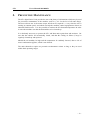
5. PREVENTIVE MAINTENANCE
33
6. TROUBLE-SHOOTING
34
7. EMC
35
7.1. G ENERAL ______________________________________________________________ 35
-4-
ST1
User's Manual 024.8080.D
7.2. C ABINET DESIGN ________________________________________________________ 36
7.3. C ABINETS CONFIGURATION _______________________________________________ 37
7.3.1. EXAMPLE 1
37
7.3.2. EXAMPLE 2
38
7.4. D ETAILS _______________________________________________________________ 39
7.4.1. R ESOLVER' S CABLE WIRING (ST1 SIDE)
39
7.4.2. M OTOR' S CABLE(S) WIRING (ST1 SIDE)
39
7.4.3. M OTOR AND RESOLVER CABLE WIRING (MOTOR SIDE)
40
7.4.4. S UPPLY' S AND BRAKING RESISTOR' S CABLE WIRING (BA4 SIDE)
41
7.4.5. B RAKING RESISTOR' S CABLE WIRING (RESISTOR SIDE)
41
7.4.6. C ONNECTION BETWEEN CONTROL CABINETS AND THE MACHINE
42
8. OUTLINES
43
8.1. BA4 AND ST1 OUTLINES _________________________________________________ 43
8.2. ST1 LINK AND OPTION BOARD ASSEMBLY ___________________________________ 44
8.3. ST1 AND BA4 BOTTOM VIEW _____________________________________________ 45
8.4. ST1 UPPER VIEW _______________________________________________________ 46
8.5. D YNAMIC BRAKING RESISTORS ____________________________________________ 47
8.6. EMC FILTERS __________________________________________________________ 48
9. WIRING DIAGRAMS
49
9.1. P OWER WIRING AND SAFETY DEVICES _____________________________________ 49
9.2. M OTOR WIRING ________________________________________________________ 50
9.3. R ESOLVER WIRING ______________________________________________________ 50
9.3.1. S INGLE RESOLVER WIRING
50
9.3.2. W IRING A SECOND RESOLVERS
51
9.3.3. W IRING A RESOLVER AND A POTENTIOMETER
52
9.4. LPO LINK BOARD WIRING _______________________________________________ 53
9.4.1. F UNCTIONAL DIAGRAM
53
9.4.2. B INARY INPUTS SCHEMATICS
53
9.5. LIO LINK BOARD WIRING ________________________________________________ 54
9.5.1. F UNCTIONAL DIAGRAM
54
-5-
User's Manual 024.8080.D
ST1
9.5.2. B INARY INPUTS AND OUTPUTS SCHEMATICS
55
9.5.3. J UNCTION MODULE OUTLINES AND SCHEMATICS
56
9.5.4. S ERIAL LINK WIRING
57
9.6. LS LINK BOARD WIRING _________________________________________________ 58
9.6.1. F UNCTIONAL DIAGRAM
58
9.6.2. B INARY INPUTS SCHEMATICS
58
9.6.3. RS485 SERIAL LINK
59
9.6.4. MA (TTY) SERIAL LINK
59
9.7. LA LINK BOARD WIRING _________________________________________________ 60
9.7.1. F UNCTIONAL DIAGRAM
60
9.7.2. B INARY INPUT(S) SCHEMATICS
60
9.7.3. A NALOG INPUT SCHEMATICS
61
9.8. OM AND OS OPTIONAL BOARD WIRING ____________________________________ 62
9.9. OEI OPTIONAL BOARD WIRING ___________________________________________ 63
9.9.1. W IRING DIAGRAM
63
9.9.2. I NCREMENTAL INPUT TYPES
64
9.10. OIO OPTIONAL BOARD WIRING __________________________________________ 65
-6-
ST1
1.
User's Manual 024.8080.D
INTRODUCTION
1.1. GENERAL DESCRIPTION
Associated to three-phase AC synchronous (DC brushless) or asynchronous (induction)
motors, the ST1 digital motion controllers with integrated power sections are used for
controlling the moving parts of all kinds of industrial machines.
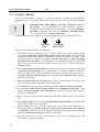
1.2. SAFETY CONSIDERATIONS
The ST1 products are using electrical voltages which may be dangerous
to humans.
While servicing ST1 devices, handling mistakes may result in
uncontrolled movements of machine parts and thus be dangerous to
humans and dangerous toward the machine and the environment.
Servicing and Maintenance require thus sufficiently trained
persons, according to local laws.
Servicing and Maintenance personal must thus always refer to the
machine manufacturer's instructions first.
1.3. USING THIS DOCUMENT
This document provides for summarized information to the machine designer.
It also informs the machine End User about the ST1 products maintenance and servicing,
but should only be used then as a complement to the machine manufacturer's instructions.
For more information please refer to the detailed documentation. The latest issue of ACC
document 080.8010 "Technical Documentation of SOCAPEL' s Products" lists all the
documents which are available (also available in German and in French) and their part
numbers.
-7-
User's Manual 024.8080.D
ST1
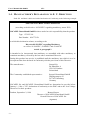
1.4. MANUFACTURER' S DECLARATION TO E. U. D IRECTIVES
Each ST1 and BA4 is delivered with a Declaration of Conformity as the following example:
MANUFACTURER' S DECLARATION
(according to the directive 89/392/EEC regarding machinery, annex II B)
SOCAPEL Deutschland GmbH declares under her sole responsibility that the product
Type
ST1/25-310
Part Number 024.7751.B
to which this declaration relates, according to the
Directive 89/392/EEC regarding Machinery
as well as 91/268/EEC, 93/44/EEC and 93/68/EEC
Article 4, paragraph 2
is intended to be incorporated into machinery or assembled with other machinery to
constitute machinery covered by the here above mentioned Directive.
Putting this product into service is prohibited until the machinery into which it is to be
incorporated has been declared in conformity with the provisions of this Directive.
The manufacturer :
Socapel SA
En Montillier 4
CH-1303 Penthaz
Switzerland
The Community established representative :
Socapel Deutschland GmbH
Zähringerstrasse 23
D-77652 Offenburg
Germany
SOCAPEL SA and SOCAPEL Deutschland GmbH are determined to provide before
January 1, 1996 a "CE" declaration of conformity to the EMC and to the Low-Voltage
Directives for their products.
Penthaz, September 2, 1994
Bernard Jaquet
Director of SOCAPEL Deutschland GmbH
General Director of SOCAPEL SA
(signature)
-8-
ST1
2.
User's Manual 024.8080.D
PRODUCT DESCRIPTION
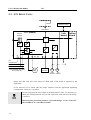
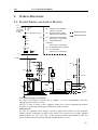
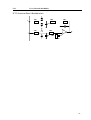
2.1. HARDWARE CONCEPT
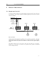
A ST1 drive system is made out of one BA4 Supply Unit and several ST1 Drive Units (one
for each motor). This concept is optimal for multiaxis application, but can also be used for
single-axis machines.
3 phase Main
PE
Protection
and switches
Isolation
transformer
Signals
Signals
ST1
ST1
3
2
BA4
Auxiliary supply
4
4
3L+PE
4
3L+PE
DC-bus interconnection
M
M
DISTANCE LIMITS
The BA4 and ST1 units should be assembled as close as possible to each other. The whole
extend of the DC bus should not exceed 1 meter, or 2 meters if the BA4 is in the middle.
Should longer distances be required, than additional, isolated 48 VDC supplies might be
needed.
The distance between any ST1 unit and its motor has been tested up to 100 meters.
Distances up to 200 meters are assumed to be possible but may produce an additional
resolver reading inaccuracy.
-9-
User's Manual 024.8080.D
ST1
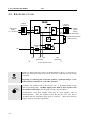
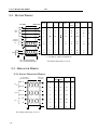
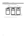
2.2. BA4 SUPPLY UNITS
BA4
Isolation
transformer
Isolation
transformer
+
Main power
supply
(3 ~ / 50-60 Hz)
+
Auxiliary
supply
(option)
220V
AC (or floating 310V DC supply)
220V
AC
Dynamic braking resistor
(with protection)
DC
DC
Grounding
strap
PE
PE
0V
UA
(310V DC)
UB
(48V DC)
Interconnection to ST1
- 10 -
In order to protect the lower edges of all BA4 and ST1 units, it is necessary to
attach one "IP20 protection set" p/n 024.7820 below each unit once the wiring
is realized.
Forgetting or removing this protection produces a potential danger as one
of the DC-bus terminal is at a 310 VDC potential.
Normally, the negative rail of the DC-bus "0V" is grounded thanks to the
built-in grounding strap. All BA4 Supply Units must be used together with
an isolation transformer (one floating secondary for each BA4).
Exceptionally, some BA4 Supply Units may be used together with an
autotransformer. Then, the negative rail of the DC-bus "0V" may not be
grounded and the grounding strap must be removed. Check then that the
supply "neutral" is properly grounded.
ST1
User's Manual 024.8080.D
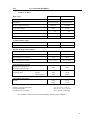
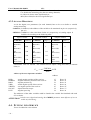
TECHNICAL DATA
Main supply
BA4/30-50
BA4/60-80
220 VAC
220 VAC
140 to 250 VAC
140 to 250 VAC
310 VDC
310 VDC
8 kW
16 kW
Max. input surge current :
225 Arms
600 Arms
Auxiliary supply voltage :
200 to 380 VDC
200 to 380 VDC
or : (floating AC-current only)
140 to 270 VAC
140 to 270 VAC
Auxiliary DC voltage output:
48 VDC
48 VDC
Current available for ST1's :
4.8 A
10 A
Switch-on threshold :
355 VDC ± 1 %
355 VDC ± 1 %
Peak braking power :
17 kW
28 kW
50 A
80 A
7.9 ½ ± 10 %
4.9 ½ ± 10 %
20 W
20 W
90 W
40 W
150 W
80 W
4.5 kg
10 lbs
6.5 kg
14 lbs
Three-phase supply voltage (nominal) :
Tolerances :
DC bus voltage (nominal) :
Cont. power output :
48 VDC auxiliary supply
Dynamic braking resistor chopper
Max. braking resistor current :
Min. braking resistor value :
Power dissipation (typical)
No load power dissipation
(dissipated in the housing) :
Additional dissipation at full load
(mounting plate)
rectifier :
shunt regulation :
General data information
Weight
Ambient operating temperature :
Storage temperature :
Maximum relative humidity :
0 to 50 °C (0 to +122 °F)
-25 to 70 °C (-13 to +158 °F)
95 % (without condensing)
For outlines, connector position and markings please refer to chapter 7.
- 11 -
User's Manual 024.8080.D
ST1
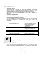
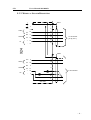
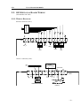
2.3. ST1 DRIVE UNITS
Servicing PC
RS232
Machine control
Test device
ST1 (basis)
Link Option
board board
internal
supplies
µP
PE
UB (48V DC)
6
6
0V
I/O
UA (310V DC)
Interconnection from BA4
and to other ST1
M
Thermal
protection
RA
RB
Main
2nd
resolver resolver
Please note that each ST1 must always be fitted with a link board as required by the
application.
It has moreover to be fitted with the proper firmware and the application depending
configuration. Refer to § 2.4 bellow.
- 12 -
In order to protect the lower edges of all BA4 and ST1 units, it is necessary to
attach one "IP20 protection set" p/n 024.7820 below each unit once the wiring
is realized.
Removing this protection produces a potential danger as one of the DCbus terminal is at a 310 VDC potential.
ST1
User's Manual 024.8080.D
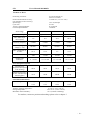
TECHNICAL DATA
Positioning resolution :
25,736 increments per
resolver revolution
± 1/8500 rev. (± 2.5 arc. min.)
Position measurement accuracy :
(not including resolver accuracy)
Speed range :
Cycle time :
Velocity signal bandwidth :
Current loop bandwidth :
± 0 to 22,500 rpm
0.33 ms
up to 600 Hz
>1000 Hz
Power stage
ST1/10
ST1/25
ST1/80
ST1/140
DC bus voltage
up to 360 VDC
up to 360 VDC
up to 360 VDC
up to 360 VDC
Max. RMS output
current (Irms)
7A
18 A
56 A
100 A
9.8 kHz
9.8 kHz
9.8 kHz
9.8 kHz
Auxiliary supply
voltage ( ± 1 %)
48 VDC
48 VDC
48 VDC
48 VDC
Max. consumption at
48 VDC
0.8 A
0.8 A
2A
0.8 A
3mH
1.2 mH
0.4 mH
0.2 mH
11...43 mH
4.6...18 mH
1.8...8.2 mH
0.4...1.5 mH
40 W
40 W
50 W
50 W
70 W
180 W
600 W
930 W
6 kg
6 kg
8 kg
16 kg
13 lbs
13 lbs
18 lbs
35 lbs
Switching frequency
Min. load inductance
Optimal load
inductance
Power dissipation (typical)
No load power
dissipation (dissipated
in the housing)
Additional dissipation
at max. load (through
mounting plate)
General data information
Weight
Ambient operating temperature :
Storage temperature :
Maximum relative humidity :
0 to 50 °C (0 to +122 °F)
-25 to 70 °C (-13 to +158 °F)
95 % (without condensing)
For outlines, connector position and markings please refer to chapter 7.
- 13 -
User's Manual 024.8080.D
ST1
2.4. ST1 SOFTWARE
APPLICATION SOFTWARE
All ST1 Drive Units are now fitted with a non volatile EEPROM for memorizing the
appropriate software. This software is supplied separately as a PC-file on a 3.5" floppy,
which has to be downloaded using the maintenance PC or the operation serial link.
Elder ST1 Drive Units were fitted with an EPROM as software memory, which had to be
plugged-on.
CONFIGURATION (PARAMETERS)
The Drive configuration is also memorized within a non volatile EEPROM, and can also be
download using the same links. Single parameter changes are possible.
CONFIGURATION (SEQUENCER AND CAM-SHAFT)
If the LIO Link Board is used, a sequence program and in some cases a cam-shaft table are
memorized in a similar way into an EEPROM non volatile memory. They are also
downloadable.
FOR MORE INFORMATION ABOUT…
REFER TO DOCUMENT (latest edition)…
program (software, firmware):
p/n 024.8072 "Software Versions"
p/n 024.8008 "basic software"
or 024.8068 "software for
synchronization"
parameter:
§ 3.4 of this document
p/n 024.8008 or 024.8068 "basic
software"
sequencer:
p/n 024.8020.A "LIO link board"
cam-shaft table:
p/n 024.8088 "cam-shaft function"
downloading from servicing PC:
p/n 024.8038 "Socasin Expert"
downloading from operation link:
p/n 024.8068.A "basic software", §10.9
The ST1 Drive Unit operation depends from the software and the
configuration which were loaded.
Using for any application a software or a configuration file which
correspond to another application may lead to incorrect operation and
damage the motor and the machine.
2.5. SERVICING TOOLS
The PC-DOS software "The SOCASIN Expert" (p/n 024.7101 or 024.7102) , which
includes the corresponding documentation (p/n 024.8038), provides for a comprehensive
interface between the user and the ST1 Drive Units.
Following devices are necessary:
• Test Device p/n 024.7701.B
• PC (refer to document p/n 024.8038 "Socasin
Expert" for more information)
• Cable p/n 024.7059
• Multimeter
• (digital storage) oscilloscope
- 14 -
ST1
User's Manual 024.8080.D
2.6. ACCESSORIES
2.6.1. MOTORS
ACC provides for several ranges of motors which differ by their technology, their data and
their price-to-performance ratio:
BAUTZ motors:
Permanent-magnet, synchronous servo-motors
0.4 to 20 Nm rated torque range
FLENDER-ATB-LOHER motors:
Asynchronous (induction) servo-motors
0.4 to 30 kW rated power range
Gear-fitted motors also available
RAGONOT motors:
Permanent-magnet, synchronous servo-motors
0.6 to 30 Nm rated torque range
SEM motors:
Permanent-magnet, synchronous servo-motors
0.4 to 60 Nm rated torque range
others:
in preparation
These motors have been tested together with ST1 Drive Units, their assembly and
particularly their built-in resolver comply with ACC specifications. Using motors made by
other manufactures is generally possible, but requires previously some sample-tests to be
performed by ACC. Ask for more information.
!
Using motors without previous acceptance by ACC may result in incorrect
operation or poor performances.
2.6.2. POWER TRANSFORMERS
ACC provides also for power transformers for supplying ST1 systems. Their main data
are:
Nominal Power:
0.85, 2.0, 4.0, 7.0, 12, 18 or 22 kVA
Primary Voltage:
400 VAC (50 or 60 Hz, three-phase)
several adjustment terminal configurations
Secondary Voltage:
220 VAC at rated load
228 VAC max. at no load
Other transformers can also be supplied. Ask ACC for additional information.
The no-load secondary voltage must be lower or equal to 228 VAC, when
the primary voltage is at its nominal value (i.e. 400 VAC) in order to allow a
+10% main voltage change.
Use isolation transformers only.
!
Autotransformers may be used for special applications, but the ST1 system
specifications are no more guaranted by ACC. Refer to §2.2.
- 15 -
User's Manual 024.8080.D
ST1
2.6.3. CONNECTOR SETS
The ST1 Drive Units are supplied with the mating motor and thermoswitch plugs.
All other mating plugs are supplied separately as connector sets. Refer to price list for part
numbers. The user may also order these connectors anywhere else; he is then responsible
for their compatibility.
Connector sets are available as:
• Resolver-to-ST1 connector set
• Link board connector set
• Option board connector set
• Motor connectors
When using the 2nd. resolver input, the "2 resolver adapter" (p/n 024.7063) should be
used.
Pre-confectioned fiber-optic cables are also available in different lengths as follow:
• LPO and PAM interconnection
• OM and OS interconnection
2.6.4. COOLING HEATSINKS
(text to be added in a next edition)
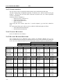
2.6.5. DYNAMIC BRAKING RESISTORS
ACC suggests the use of following power resistors for Dynamic Braking (see §3.2.5).
They are IP40 protected and may be assembled on the roof of the enclosure for getting rid
in an easier way of their thermal load. The dimensions of these resistors are shown in §7.5.
Pinst=20...25 kW
Type
PW
FWA 40-150
FWA 40-200
FWA 40-300
FWA 40-400
FWA 60-300
FWA 60-400
FWA 60-500
120
180
300
400
450
600
800
5.1
5.8
5.1
5.0
5.3
5.3
5.1
231.1051
231.1086
231.1119
231.1153
231.1189
231.1223
231.1258
8.8
9.6
9.5
8.6
8.9
8.6
7.9
231.1053
231.1088
231.1122
231.1156
231.1192
231.1226
231.1260
12.0
12.8
12.0
13.2
13.5
12.5
13.2
231.1055
231.1089
231.1123
231.1158
231.1194
231.1228
231.1263
Type
PW
R(Ohms)
Ref. ACC
R(Ohms)
Ref. ACC
R(Ohms)
Ref. ACC
FWDA 40-150
FWDA 40-200
FWDA 40-300
FWDA 40-400
FWDA 60-300
FWDA 60-400
FWDA 60-500
240
360
600
800
900
1200
1600
5.1
6.4
6.0
5.2
5.5
5.1
5.5
231.2154
231.2189
231.2238
231.2319
231.2384
231.2429
231.2506
8.5
8.7
10.2
8.4
8.5
9.5
9.0
231.2157
231.2191
231.2242
231.2327
231.2386
231.2435
231.2514
12.5
12.5
12.0
14.5
15.0
12.0
12.0
231.2159
231.2193
231.2244
231.2335
231.2388
231.2437
231.2522
Type
PW
R(Ohms)
Ref. ACC
R(Ohms)
Ref. ACC
R)Ohms)
Ref. ACC
FWTA 40-150
FWTA 40-200
FWTA 40-300
FWTA 40-400
FWTA 60-300
FWTA 60-400
FWTA 60-500
340
540
900
1200
1350
1800
2400
5.7
5.8
5.2
5.6
5.7
5.1
5.3
231.3657
231.3691
231.3740
231.3827
231.3886
231.3933
231.4014
8.3
8.3
8.0
9.7
10.0
8.0
8.0
231.3659
231.3693
231.3744
231.3835
231.3888
231.3937
231.4022
13.3
12.3
13.3
13.0
13.7
14.0
13.3
231.3000
231.3095
231.3750
231.3843
231.3890
231.3941
231.4030
- 16 -
R(Ohms)
Ref. ACC
BA4 / 30-50-310
BA4 / 60-80-310
Pinst=12...16 kW
Pinst=8...10 kW
R(Ohms)
Ref. ACC
R(Ohms)
Ref. ACC
ST1
User's Manual 024.8080.D
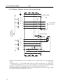
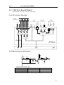
2.6.6. EMC FILTERS
EMC filters shall be chosen so that national electrical regulations are fulfilled in the country
where the system is to be used. The filters used shall be tested to comply with the EMC
regulations. ACC SA recommends the filters listed in below. Other filters will be added in
a next issue of this manual.
Type
Rated current Leakage curr. Losses
ΣCx
L
ΣCy
R1
at 40°C
(At 400V,50Hz)
[Arms]
max [mA]
[W]
FN351-25/33
25
160
8
2.2
4.4
1.8
1.5
FN351-50/33
50
175
11
0.8
4.4
2
1.5
FN2010-3/6
3
0.4
2.5
0.1
4.7
1
[mH] [µF]
R2
p/n
Recommended
for FA4
1.1
410.0125
BA4 / 30-50-310
1.1
410.0129
BA4 / 60-80-310
410.0031
Auxiliary supply
of all BA4
[µF] [MΩ] [MΩ]
FN351:
Line
L
Cx
R1
L1
L2
L2
L3
L3
Cy
R2
Load
Cx
L1
Cy
PE
PE
sta005_a.dsf / 18.12.96
FN2010
R1
L
L
L
N
N
Load
Line
Cx
Cy
PE
sta006_a.dsf / 18.12.96
- 17 -
User's Manual 024.8080.D
3.
ST1
APPLICATION DESIGN CHECK-LIST
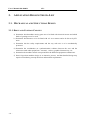
3.1. MECHANICAL AND STRUCTURAL DESIGN
3.1.1. DRIVE AND CONTROL CONCEPT
a) Determine which machine moving parts are to be fitted with electrical motors and which
kinds of gearings are to be used.
b) Determine which motors are to be fitted with AC servo-motors and to be driven by ST1
units.
c) Determine also the safety requirements and the way each axis is to be mechanically
protected.
d) Determine the coordination (or synchronisation) relations between the axes and the
relations toward other equipments: actuators, sensors, graphical interactivity, etc.
e) Determine the machine control concept and how the different equipment communicate.
f) Don' t forget that machine design is an itterative process, and that detailed design may
require reconsidering concept decisions and machine requirements.
- 18 -
ST1
User's Manual 024.8080.D
3.1.2. MOTOR AND GEARING SELECTION
a) Investigate the mechanical load for each axis (inertia, friction, erratic forces or torques,
etc.).
Here are some helpful formulae:
As a first approximation: Tmot [ Nm] =
∑ J [kgm ] ⋅ α [rad / s ] + ∑ T
2
2
mot
motz
ROTARY MOTION
load mot
[ Nm]
LINEAR MOTION
n2
Load
n1
Motor
Motor
n2
Load
n1
Gear Box
msc002_a.dsf / 8.10.96
msc001_a.dsf / 8.10.96
Gear ratio: i
Coupling
Speed
Acceleration
Torque
ω mot [rad / s] = ω load [rad / s] ⋅ i
π
ω [rad / s] = n[rpm] ⋅
30
α mot rad / s = α load rad / s ⋅ i
[
Tload
mot
2
[ Nm] =
Inertia
J load
]
[kgm ]
2
mot
[
2
Tload [ Nm]
i
J load kgm
=
i2
]
[ ]
Pitch: h[m]
2π ⋅ vload [m / s]
h[m]
ω mot [rad / s] =
α mot
[rad / s ] =
2
2π ⋅ α load
[m / s ]
2
h[m]
hm
[ Nm] = Fload [ N ] ⋅ [π ]
Tload
mot
Jload
mot
3
[kgm ]
2
2
h[m]
= mload [kg ] ⋅
2π
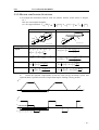
b)
Define the dynamic requirements (worst-case and average movement cycles) and
represent them if possible in terms of equivalent trapeze-looking velocity profiles.
ω
time
1 cycle
Τ
Τ1
Τ2
time
1 cycle
t1
t2
t3
t4
Τ3
- 19 -
User's Manual 024.8080.D
ST1
c) Choose the motor and gearing ratio from the inertia and temperature points of view.
This choice may be done using the motor selection tool which is available together with
"The SOCASIN Expert" software (p/n 024.7101 or 024.7102, release 1.5) and runs
under Microsoft EXCEL.
d) Select the winding (or Kt) option in order to reach the peak velocity and peak torque as
required. This choice may be done using ACC's motor selection guides.
In most applications, consider that the motor must be able to reach this working
condition at 170 Vrms phase-to-phase voltage. The difference between this voltage and
the BA4 input rated voltage (220 Vrms) provides for enough security toward main
voltage lowering (down to -10%), the voltage drops both within the transformer, the
rectifier and the power electronics.
!
Always consider that these choices which are based mostly on machine
modelling have to be confirmed by comprehensive machine prototype testings.
3.2. POWER HARDWARE DESIGN
3.2.1. ST1 UNITS SELECTION
a) Select the ST1 Drive Unit depending on the peak current that the selected motor needs
for delivering the peak torque.
b) Estimate for each axis the output current rms value (average time τ adjusted to a typical
machine cycle).
I rms
1
1
≈
⋅ Trms =
kT
kT
t +τ
1
⋅ ∫ T 2dt
τ t
This is the general form which becomes for a trapeze looking velocity profile:
I rms ≈
1
kT
T12 ⋅ t1 + T22 ⋅ t2 +...+ Tn2 ⋅ t n
t1 + t2 +...+ t n
In exemple for the profile shown on page 16:
I rms ≈
1
kT
T12 ⋅ t1 + T22 ⋅ t2 + T32 ⋅ t 3
t1 + t2 + t 3 + t 4
c) If this rms current is close to the peak current, the ST1 cooling design (§3.2.8 below)
may show that the next larger ST1 size has to be chosen instead.
d) Check that the motor inductance (stray inductance for induction motors) fits to the ST1
"optimal load inductance" (refer to § 2.3 "technical data").
- 20 -
ST1
User's Manual 024.8080.D
3.2.2. BA4 UNITS SELECTION
a) Estimate for each axis the peak value both of the positive (acceleration) and the negative
(deceleration) power which are required.
The positive peak power must be devided by the motor efficiency (the electrical power
need from the main is higher than the motor shaft output power).
Ppos peak =
1
1
⋅ Tposmax ⋅ ω posmax or ⋅ Tneg max ⋅ ω neg max
η
η
The negative peak power must be multiplied by the motor efficiency (the electrical power
returned to the DC bus is lower than the motor shaft input power).
Pneg peak = η ⋅ Tneg max ⋅ ω posmax
or
η ⋅ Tposmax ⋅ ω neg max
The formulae above are true for trapeze profile point-to-point movements. An axis
which follows a cam-shaft profile requires generally smaller peak powers, which are
reached when the products ω ⋅ dω dt are maximum (positive) and minimum (negative).
b) Considering all the axes and their individual movement cycles within the whole machine
cycle, estimate for the whole machine (or for each group of ST1 Units if several BA4
Supply Units are to be used) the peak positive and the peak negative powers. Assuming
that all axes accelerate and decelerate together at the same time is the worst case
condition. More accurate figures may be computed if that is not the case.
Paccel peak ≤
∑P
pos peak
∑P
Pdecel peak ≤
All Axes
neg peak
All Axes
c) Estimate in the same way as "a" for each axis the average values of both the positive and
negative power which is required for each axis.
At constant speed: Pcst . speed =
1
⋅ T ⋅ω
η cst cst
While accelerating: Paccaverage =
1 Tacc ⋅ ω max
⋅
η
2
While decelerating: Pdecaverage = η ⋅
Tdec ⋅ ω max
2
Average positive power: Pposaverage =
Average negative power: Pneg average =
( negative)
Pcst . speed 1 ⋅ t1 + Pcst . speed 2 ⋅ t2 +...+ Paccaverage ⋅ tacc
τ full cycle
Pdecaverage ⋅ tdec
τ full cycle
d) Estimate also in the same way as "b" for the whole machine the average positive and
negative powers for all axes together.
e) Select the smallest BA4 Supply Unit that yet fits to the "machine" power values above.
f) Check that this BA4 size meets the 48 VDC auxiliary supply requirement of all ST1
units.
- 21 -
User's Manual 024.8080.D
ST1
3.2.3. POWER TRANSFORMER SELECTION
a) Select the smallest power transformer whose power rating yet is larger than the average
positive power required for all axes. Refer to §2.6.2 for the list of ACC standard
transformers.
b) Make sure that the peak positive power of the machine is not more than about 4 times the
transformer rated power, in order to limit its voltage drop.
3.2.4. POWER TRANSFORMER AND BA4 PROTECTION
a) Select the protective elements (fuses, etc.) according to the rated primary current of the
Power Transformer.
b) Check that this protective elements meet the standard requirements for short-circuit
protection coordination.
c) Several ACC' s standard Power Transformers are fitted with thermal protection switches
which take care of the secondary wiring protection. If such a thermal protection is not
available, then fuses (or alike) are also necessary on the transformer secondary side.
d) If the Power Transformer power rating is larger than 2 kVA (BA4/30-50-310) or
4.5kVA (BA4/60-80-310), an external in-rush current limitation is necessary. Refer to
the figure of § 8.1.
3.2.5. DYNAMIC BRAKING RESISTOR SELECTION
a) The average negative power (Pneg. average) gives you the power of the resistor (PW in table
§2.6.5).
b) Choose the ohmic value considering the BA4 Unit size and the peak negative power
(Pneg.peak , P inst. in the table §2.6.5) of the machine.
3.2.6. DYNAMIC BRAKING RESISTOR PROTECTION
a) Estimate the max. continuous DC current that the Resistor stands under 360 VDC:
I max [ A] =
Presistor rating [W ]
360[V ]
b) Select a thermal relay which can be adjusted to this current. Its signalling contact has to
be used for switching-off the main power supply to the BA4 Unit.See figure of § 8.1.
3.2.7. EMERGENCY BRAKE RESISTORS SELECTION
a) Take the motor speed constant and its maximum speed and calculate the corresponding
VM (effective voltage between phases).
b) From the maximum torque or the demagnetisation determin the maximum braking
current IM (effective current in a phase).
c) Calculate the ohmic value of the resistor: REBR =
- 22 -
VM
R
− mot
2
IM ⋅ 3
ST1
User's Manual 024.8080.D
Rmot.: Interphase motor's resistance.
d) Caluculate its power value: PREBR ≈ 1 60 ⋅ J ⋅ ω 2
J: System inertia and ω:Motor speed [rad/s].
This approximation is valid up to two emergency braking per minute.
For more details, refer to the latest edition of document p/n 024.8028 "The Motor"
(§3.2) .
3.2.8. COOLING THE BA4 AND ST1 UNITS
Refer to the latest edition of document p/n 024.8054 "Thermal Dimensioning".
- 23 -
User's Manual 024.8080.D
ST1
3.3. DEFINING THE ST1 PARAMETERS
Once the proper software has been chosen (refer to §2.4), each ST1 has to be configured.
It means that several application dependent settings have to be defined and loaded as
parameters.
The following tables shows which parameters are concerned depending on the application,
and in which document additional information can be found. The shaded ones have
absolutely to be defined even for a preliminary test; the others can be used for enhanced
performance.
All parameters which are not concerned for an application should remain unchanged at their
"default value".
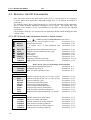
3.3.1. ST1 PARAMETERS NECESSARY FOR ALL APPLICATIONS
Motor
NPPOL
KTINV
KIGLIN
IMAGNN
VITN
VITMAX
COUMA
CURES
COULIM
CDEPHA
Status & Safety
CMASKU
CMASKA
CMASKS
Refer also to § 6.2 for the meaning of all status bits
Power stage desabling mask (Stop 0)
024.8068.A §6.3
Controlled stop (Stop 2)
024.8068.A §6.3
Mask for status signalling to host
024.8068.A §6.3
Pos./Vel. Contr.
KPOS
KVIT
KTEGR
DPOMA
SEUIL1
INERT
FVISC
FSEC
FEXT
Position controller P gain (or vel. contr. I gain)
Position controller D gain (or vel. contr. P gain)
Position controller I gain
Position lag measurement limit
Position lag warning threshold
Feed-forward inertia modelisation
Feed-forward viscosity modelisation
Feed-forward dry friction modelisation
Feed-forward weight modelisation (cst. torque)
024.8068.A §7.5.4
024.8068.A §7.5.5
024.8068.A §7.5.6
024.8068.A §7.5.11
024.8068.A §7.5.12
024.8068.A §7.5.7
024.8068.A §7.5.8
024.8068.A §7.5.9
024.8068.A §7.5.10
Variable selection for igital output
Test device enable and disable
Variable selection for analog output #1
Gain selection for analog output #1
Variable selection for analog output #2
Gain selection for analog output #2
024.8068.A §7.7.2
024.8068.A §7.7.2
024.8068.A §7.7.3
024.8068.A §7.7.3
024.8068.A §7.7.4
024.8068.A §7.7.4
Test Board
CADBIN
CMPBIN
CADMA1
CMPMA1
CADMA2
CMPMA2
- 24 -
= Refer to ACC's motor libraries (024.8038.C)
Motor pole nb. / Resolver pole nb. ratio
024.8068.A §7.3.3
Motor torque constant
024.8068.A §7.4.3
= 0 (synchr. mot.) or dlip adjustment (ind. 024.8068.A §7.4.4
mot.)
Magentizing current (induction motor only)
024.8068.A §7.4.5
Nominal Velocity (induction motor only)
024.8068.A §7.4.6
Peak velocity
024.8068.A §7.4.7
Peak torque
024.8068.A §7.4.8
Resolver Supply
024.8068.A §7.3.1
Temporary reduced peak torque
024.8068.A §7.5.14
Angle offset between motor and resolver
024.8068.A §7.4.2
ST1
User's Manual 024.8080.D
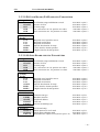
3.3.2. LPO LINK BOARD (PAM) SPECIFIC PARAMETERS
Length Units
CKA
CKAINV
CKV
CKR
CKH
Acceleration range and Motion reversal
Inverse of CKA
Velocity range
1st. conversion cste. for position set values
2nd. conversion cste. for position set values
024.8068.A §8.4.3
024.8068.A §8.4.3
024.8068.A §8.4.4
024.8068.A §8.4.13
024.8068.A §8.4.13
Velocity
Profile
CVP
CA1
CA2
ASTOP
PHIL1
PHIL2
Required travel speed for moves
Required acceleration
Required deceleration
Specific deceleration for stops
"Left" limit for absolut position
"Right" limit for absolut position
024.8068.A §8.4.6
024.8068.A §8.4.8
024.8068.A §8.4.8
024.8068.A §8.4.9
024.8068.A §7.8.2
024.8068.A §7.8.3
3.3.3. LIO LINK BOARD SPECIFIC PARAMETERS
Length Units
CKA
CKAINV
CKV
CKR
CKH
Acceleration range and Motion reversal
Inverse of CKA
Velocity range
1st. conversion cste. for position set values
2nd. conversion cste. for position set values
024.8068.A §8.4.3
024.8068.A §8.4.3
024.8068.A §8.4.4
024.8068.A §8.4.13
024.8068.A §8.4.13
Velocity
Profile
CVP
CA1
CA2
ASTOP
PHIL1
PHIL2
Required travel speed for moves
Required acceleration
Required deceleration
Specific deceleration for stops
"Left" limit for absolut position
"Right" limit for absolut position
024.8068.A §8.4.6
024.8068.A §8.4.8
024.8068.A §8.4.8
024.8068.A §8.4.9
024.8068.A §7.8.2
024.8068.A §7.8.3
Serial Link
LSMR1
LSMR2
ADAXE
TIMOUT
ENDBYT
Transmission type
Baudrate selection
Peripheral address
Time-out
Answer terminating byte
024.8020.A §5.2.1
024.8020.A §5.2.2
024.8020.A §5.2.3
024.8020.A §5.2.4
024.8020.A §5.2.5
Sequencer
CINACL
CINMAS
ZMANAL
(LIO board only)
Initial input active level mask
Initial input validation mask
Dead-band for output OUT6 (motor speed = 0)
024.8020.A §5.3.1
024.8020.A §5.3.2
024.8020.A §5.3.3
- 25 -
User's Manual 024.8080.D
ST1
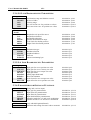
3.3.4. LS LINK BOARD SPECIFIC PARAMETERS
Length Units
CKA
CKAINV
CKV
CKR
CKH
Acceleration range and Motion reversal
Inverse of CKA
Velocity range
1st. conversion cste. for position set values
2nd. conversion cste. for position set values
024.8068.A §8.4.3
024.8068.A §8.4.3
024.8068.A §8.4.4
024.8068.A §8.4.13
024.8068.A §8.4.13
Velocity
Profile
CVP
CA1
CA2
ASTOP
PHIL1
PHIL2
Required travel speed for moves
Required acceleration
Required deceleration
Specific deceleration for stops
"Left" limit for absolut position
"Right" limit for absolut position
024.8068.A §8.4.6
024.8068.A §8.4.8
024.8068.A §8.4.8
024.8068.A §8.4.9
024.8068.A §7.8.2
024.8068.A §7.8.3
Serial Link
LSMR1
LSMR2
ADAXE
TIMOUT
ENDBYT
Transmission type
Baudrate selection
Peripheral address
Time-out
Answer terminating byte
024.8012 §5.2
024.8012 §5.3
024.8012 §5.4
024.8012 §5.5
024.8012 §5.6
3.3.5. LA LINK BOARD SPECIFIC PARAMETERS
Analog Input
COEPOS
COEVIT
COEACC
MGAIN
ZMANAL
DIFANA
INERT
DECZER
Input gain for use as position set value
Input gain for use as velocity set value
Input gain for use as torque set value
Input gain mode
Analog input dead-band
Slew-rate limitation
Scale factor for use as torque set value
Input offset for use as position set value
024.8016 §4.2
024.8016 §4.3
024.8016 §4.4
024.8016 §3.4
024.8016 §3.5
024.8016 §3.6
024.8016 §4.4
024.8016 §4.2
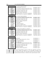
3.3.6. PARAMETERS FOR OPTIONAL FUNCTIONS
- 26 -
Potentiometer
COEPOT
OFPOT
PILTPOT
ZMPOT
MRATE
SRATE
(using 2nd. resolver input)
Input gain for potentiometer
Input offset for potentiometer
Input filter for potentiometer
Input dead-band for potentiometer
Operating mode for vel. and accel. modulation
Synchro. mode for vel. and accel. modulation
024.8068.A §8.12.4
024.8068.A §8.12.2
024.8068.A §8.12.3
024.8068.A §8.12.5
024.8068.A §8.4.10
024.8068.A §8.4.10
Master Axis
COMOS
(only with OM Optional Board)
Selection and scaling of master value to transmit
024.8068.A §8.11.2
ST1
User's Manual 024.8080.D
Slave Axis
COMOS
CKM
CKS
CRANS
CKMS
CSCAN
MRATE
SRATE
(only with OS Optional Board)
Operating mode of slave axis
1st. conversion constant for master-slave ratio
2nd. conversion constant for master-slave ratio
Scale factor for master-slave ratio
Approximative master-slave ratio
Master-slave delay compensation
Operating mode for vel. and accel. modulation
Synchro. mode for vel. and accel. modulation
024.8068.A §8.11.2
024.8068.A §8.5.2
024.8068.A §8.5.2
024.8068.A §8.5.2
024.8068.A §8.5.2
024.8068.A §8.6.2
024.8068.A §8.4.10
024.8068.A §8.4.10
Slave Axis
CKM
CKS
CRANS
CKMS
CSCAN
NIMPEI
FILTEI
ACCLIM
PISTEI
MRATE
SRATE
(only with OEI Optional Board)
1st. conversion constant for master-slave ratio
2nd. conversion constant for master-slave ratio
Scale factor for master-slave ratio
Approximative master-slave ratio
Master-slave delay compensation
Encoder resolution
Encoder filter
Acceleration limitation
Encoder zero channel enable
Operating mode for vel. and accel. modulation
Synchro. mode for vel. and accel. modulation
024.8068.A §8.5.2
024.8068.A §8.5.2
024.8068.A §8.5.2
024.8068.A §8.5.2
024.8068.A §8.6.2
024.8068.A §8.5.7
024.8068.A §8.5.4
024.8068.A §8.5.5
024.8068.A §8.5.6
024.8068.A §8.4.10
024.8068.A §8.4.10
Slave Axis
CKM
CKS
CRANS
CKMS
CSCAN
MRATE
SRATE
(only using a Second Resolver as Master)
1st. conversion constant for master-slave ratio
2nd. conversion constant for master-slave ratio
Scale factor for master-slave ratio
Approximative master-slave ratio
Master-slave delay compensation
Operating mode for vel. and accel. modulation
Synchro. mode for vel. and accel. modulation
024.8068.A §8.5.2
024.8068.A §8.5.2
024.8068.A §8.5.2
024.8068.A §8.5.2
024.8068.A §8.6.2
024.8068.A §8.4.10
024.8068.A §8.4.10
Cam-Shaft
CLGCAM
CNBREP
CSTCAM
CRCAM
OFCAM
CKM
CKS
CRANS
CKMS
COMOS
CSCAN
Cam length
Number of steps with repetitive velocity
Cam start-point pointer
Cam output scale factor
Cam input offset
1st. conversion constant for master-slave ratio
2nd. conversion constant for master-slave ratio
Scale factor for master-slave ratio
Approximative master-slave ratio
Reference transmitter
Master-slave delay compensation
024.8088 §4.2.1
024.8088 §5.2.1
024.8088 §5.2.2
024.8088 §5.3.1
024.8088 §5.2.3
024.8088.A §4.2.2
024.8088.A §4.2.2
024.8088.A §4.2.2
024.8088.A §4.2.2
024.8088.A §7.2
024.8068.A §8.6.2
!
When the cam-shaft function is used in a master-slave application, parameters
CKM, CKS, CRANS and CKMS have to be determined according to the
specific document 024.8088 "ST1-Cam-Shaft Function" and not according to
the general document 024.8068.A "Software for the synchronization of axes.
- 27 -
User's Manual 024.8080.D
4.
ST1
APPLICATION TESTING
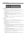
4.1. FRONT-PANEL DISPLAYS
The front-panel display shows a 7-segment sign and a decimal point. Its reading is to be
interpreted as follow:
Display
Validity
dark
any,
dot
alight
all versions
all versions
any,
dot half
alight
all versions
all versions
all versions
downloadable software
boot software
all versions
all versions
all versions
all versions
all versions
boot software
boot software
all versions except LA
boot software
all versions except LA
all versions
all versions except LA
all versions
PAM with new ASIC
PAM with new ASIC
PAM with new ASIC
PAM with new ASIC
Signification
Auxiliary supply is missing
Auxiliary supply is ok and CPU is running
In order to make sure that the dot is alight and not half-alight,
depress the reset button and release after 1 second; the dot should
show different brilliancy.
Auxiliary supply is ok, but CPU is not running or software is not
available.
(see the remark above about dot alight or half alight)
The power stage has been disabled as the result of an external
command and not because of a fault
Power stage has been enabled
No firmware available; boot program only is running
Reboot after completion of software download
Unit is ready; user's initial parameter values are active
Unit is ready; default parameter values are active
Power stage has been desabled; Auxiliary supply missing
Power stage has been desabled; Resolver failure
Power stage has been desabled; Internal supply failure
Parameter memory IC or jumper not ok or bad memory type
Memory overrun while downloading a software, or
Checksum error after software download
Power stage has been desabled; out of position end limits
Internal hardware error
Power stage has been desabled; refer to CMASKU parameter
setting
Power stage has been desabled; DC-bus overvoltage
Power stage fault test has been completed successfully
Power stage has been desabled; output had a short-circuit
CRC Ring. A CRC error has been detected.
Fail Ring. A ring error has occured.
Carrier Fail.A CRC error has been detected by another ST1.
No frame received during 50 ms.
BA4 LED's:
GREEN
Auxiliary supply OK
RED
Temperature to high
YELLOW
DC bus high
- 28 -
ST1
User's Manual 024.8080.D
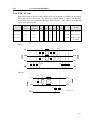
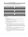
4.2. STATUS INDICATORS FOR REMOTE DIAGNOSIS
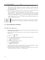
Status indicators or flags are grouped within 6 bytes (3 words). They read as follow:
msb
#7
#6
#5
#4
#3
#2
#1
lsb
msb
#0
#7
lsb
#6
#5
STATA
#4
#3
#2
#1
#0
STATB
STAT1
msb
#7
#6
#5
#4
#3
#2
#1
lsb
msb
#0
#7
lsb
#6
#5
STATC
#4
#3
#2
#1
#0
STATD
STAT2
msb
#7
#6
#5
#4
#3
#2
#1
lsb
msb
#0
#7
lsb
#6
#5
STATE
#4
#3
#2
#1
#0
STATF
STAT3 (not available in several versions)
4.2.1. STATA
The STATA byte provides essential information on the status of the ST1 digital motion
controller and its software.
Bit 7 (latched) signals that the power stage has been disabled as a result of a fault. Normal
disabling will not have any effect on this bit.
Bit 6 (latched) informs that there has been a change in the two bytes of the STATC and
STATD status as a function of the mask MASKS. .
Bit 5 indicates whether the real position is less than ("1") or greater than ("0") the value set by
the instruction SPWARN.
Bit 4 signals that the position lag (variable DPOS) is greater than ("1") or less than ("0") the
value set by the parameter SEUIL1. It provides an overall functional control of the axis,
allowing the disclosure of any occurrence of excessive friction or a cable rupture, for
example. It is resumed under the memorized format in STATD. In certain versions of the
software, velocity lag DVIT is monitored instead of the position lag if parameter KTEGR
= 32,768 (hexa : 8000).
Bit 3 signals that the move requested by an instruction ERMOV, ERUN, START, STOP etc. is
in progress. The bit is set to "1" when one of the above instructions is received and
returns to "0" when the corresponding move is finished.
Bit 2 is used by those software versions which require computation time between the receipt of
a move order and the execution of it. It is set to "1" when the computation is finished,
which means that a START order will follow immediately. It returns to "0" as soon as
the move has started
- 29 -
User's Manual 024.8080.D
ST1
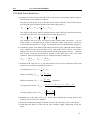
Bits 1 and 0 give information about the status of the motor speed during the execution of a
move of the axis :
Bit 1
0
0
1
1
Bit 0
0
1
1
0
Meaning
Stop (reference speed zero)
Acceleration
At speed (reference speed not zero)
Deceleration
4.2.2. STATB
The STATB byte indicates such faults which have immediately resulted in the disabling of the
power stage. It allows you to find the reasons for an undesired stop of the axis.
Bit 7 (latched) indicates the amplifier has been disabled due to a failure in the resolver
feedback signal.
Bit 6 (latched) indicates that the DC bus voltage UA has exceeded its upper limit.
Bit 5 (latched) indicates that a saturation fault in the power transistors is the source of the
disabling. Possible causes : short circuit or overload.
Bit 4 (latched) signals that an internal failure in the auxiliary voltage is the source of the
disabling.
Bit 3 (latched) indicates that a momentary interruption of the auxiliary supply is the source of
the disabling.
Bit 0 indicates that the boot program is running .
4.2.3. STATC
The effects of the bits of variable STATC depend on the masks. The listing which
accompanies every software version, shows all bits having really a meaning. All the other bits
remain set to "0".
Bit 7 (latched) indicates that a not valid instruction code has been received.
Bit 6 (latched) indicates that implausible instruction code or data has been received.
Bit 5 (latched) reserved.
Bit 4 (latched) indicates after powering up or resetting that the present link card is not
compatible with the present software version, or that the card is missing. Afterwards, it
indicates a serial link transmission failure.
Bit 3 is "1" as long as the SAVE routine is in progress, which saves all parameter actual values
into the EEPROM parameter memory. It returns to "0" as soon as saving has been
completed.
Bit 2 indicates that the master shaft has overrun the limit of one period, or that the zero track of
an incremental encoder has been detected.
Bit 1 reproduces the state of input No. 2 of some link cards. If the entry is open (no current,
zero voltage), the bit is at 1. If the entry is fed, it is at 0.
While downloading a software bit 1 indicates that the EEPROM memory filling is under
way.
Bit 0 depends on the state of input No. 1 of some link cards, as bit 1.
While downloading a software bit 0 indicates that the checksum computation is under
way.
- 30 -
ST1
User's Manual 024.8080.D
4.2.4. STATD
The effects of the bits of variable STATD depend on the masks as STATC. The listing which
accompanies every software version, shows all bits having really a meaning. All other bits
remain set to "0".
Bit 7 (latched) indicates excessive motor temperature, or that the corresponding input of the
ST1 digital motion controller is not connected.
Bit 6 (latched) indicates that the internal overheating protection circuitry is active and reducing
the current to the motor.
Bit 5 (latched) is a latched copy of bit 4 of STATA.
Bit 4 (latched) indicates that the real position has exceeded (even if only briefly) the limits set
by parameters PHIL1/PHIL2.
Bit 3 (latched) indicates that the ST1 digital motion controller has initiated a STOP procedure.
Bit 2 (latched) indicates a failure of the optional board.
Bit 1 (latched) is used to determine if the microprocessorhas been reinitialized ("RESET") or
not. The validity of the position measurement (number of turns) and the other variables
depends on it. After each restart of the microprocessor, this bit is worth 1. It is put back
to 0 by one of the initialization commands of status and particularly when the power
stage is enabled. Then, it can only go back to 1 with a new restart of the microprocessor.
Bit 0 indicates if the power stage is enabled ("0"), or disabled ("1").
4.2.5. STATE
Bit 7 indicates that a motor speed has exceeded the limit set by the parameter VITMAX.
4.2.6. STATF
This status is only used by the PAM version ***
Bit 5 (CRC NODE) indicates that ST1 has detected a CRC error in a tram destinated to it.
Bit 4 (NO TRAM) indicates that any tram is arrived for 50 ms.
Bit 3 (CARRIER FAIL) indicates that a CRC error has been detected by a ST1 upstream in
the ring.
Bit 2 (FAIL RING) indicates a ring error.
Bit 1 (CRC RING) indicates that the ST1 has detected a CRC error in a tram destinated to
another ST1.
Bit 0 (COUNT) indicates that more than two commands have been sent to the ST1 during one
PAM cycle.
4.3. TEST DEVICE
The test device allows you to measure variables in digital (8 bits) or in analog (2 channels)
form.
4.3.1. DIGITAL MEASURING
Two parameters are necessary to define which variables you want to measure:
CADBIN: is the address of the variable to be monitored digitally. Default value 128
(hexa:80): STATA
- 31 -
User's Manual 024.8080.D
ST1
CMPBIN: specifies which part of the variable has to be monitored:
0 to disable the measuring (also the two analog channels).
16 (Hexa:10) for the most significant byte.
4096 (Hexa:1000) for the least significant byte.
4.3.2. ANALOG MEASURING
As for the digital, two parameters (for each channel) have to be set to define a variable
analog measuring:
CADMA1: (CADMA2) is the address of the variable to be monitored on pin A1 (respectively
pin A2)
CMPMA1: (CMPMA2) is the scale factor for the A1 (respectively A2) analog output. It
could be set according to the following table:
Speed variable
CMPMAx
72
(Hexa:48)
144
(Hexa:90)
288
(Hexa:120)
722
(Hexa:2D2)
1444
(Hexa:5A4)
[t/min/V]
2000
1000
500
200
100
Position variable
CMPMAx
144
(Hexa:90)
288
(Hexa:120)
722
(Hexa:2D2)
1444
(Hexa:5A4)
2888
(Hexa:B48)
[deg/V]
2
1
0.5
0.2
0.1
Torquee variable
CMPMAx
82
(Hexa:52)
205
(Hexa:CD)
410
(Hexa:19A)
820
(Hexa:334)
1444
(Hexa:5A4)
[Nm/V]
5
2
1
0.5
0.2
Intermediate value are allowed. The relation between output voltage and value (in internal
units) is:
U OUT = val ⋅
CMPMAx
⋅ 0.078
4096
Address of the most important variables:
Address
PHIB
PHIREB
DPOS
VIRB
VIREFB
COCOU
DVIT
: actual angular position of the resolver
: angular reference position of the resolver
: angular position lag
: actual angular speed of the resolver
: set angular speed of the resolver
: required motor torque
: angular speed lag
37
50
53
41
47
55
52
Hexa: 25
Hexa: 32
Hexa: 35
Hexa: 29
Hexa: 2F
Hexa: 37
Hexa: 34
The addresses of the other variables could be found in the variable list furnished with each
ST1 software.
ATTENTION! In both cases (digital and analog) the CMPBIN parameter must different of zero to
enable any measuring.
4.4. PUTTING INTO SERVICE
Text to be added in a next edition.
- 32 -
ST1
5.
User's Manual 024.8080.D
PREVENTIVE MAINTENANCE
The ST1 digital Drive Units provide the user with plenty of informations which may be used
for preventive maintenance of the machine (refer to § 6.2 for the list of all status flags).
The most obvious one is the motor torque which can be required i.e. every time the axis is
running at constant speed, and which can help the machine control equipement to detect an
unnormal load increase. It is also possible to monitor the ST1 heatsink temperature in order
to warn the machine user that the heatsink has to be cleaned-up.
It is absolutely necessary to protect the ST1 and BA4 units agains dust and moisture. Be
sure that the cubicles are hermetically closed, and that the cooling air filters (if any) be
regularly cleaned-up and replaced.
Should the air humidity be high and the temperature be suddenly lowered, then a risk of
water condensation appears, which is not allowed.
The units themselves require no preventive maintenance actions as long as they are used
within their operating ranges.
- 33 -
User's Manual 024.8080.D
6.
TROUBLE-SHOOTING
(text to be added in a next edition)
- 34 -
ST1
ST1
7.
User's Manual 024.8080.D
EMC
7.1. GENERAL
Mounting ST1 into cabinets for driving machines has to take care about different points.
One of these is the EMC (ElectroMagnetic Compatibility). The EMC is the capability of a
part of a system to work without perturbing (emission) - and being perturbed by (immunity)
- the rest of the system with electromagnetic phenomena.
Electromagnetic interference are propagated by four different ways:
• Galvanic coupling
•
Capacitive coupling
•
Inductive coupling
•
Radiated electromagnetic field
EMC protection and insulation/safety requirements can have common aspects,
such as earthing and protection against overvoltages and lightning. It is
important to bear in mind that the safety aspects procedures for personnel
protection take precedence over EMC protection procedures.
Safety must always prevail, so that in such cases alternate EMC-related
measures must be sought.
Motor cable shields may carry strong, capacitively induced high-frequency
currents. These currents are normally routed to the earth and thus produce no
particular danger.
Should the user fail to connect these motor cable shields to earth, than a
voltage may appear at places which are normally not IP20 protected, and
which is dangerous to humans.
It is recommended to design a meshed earthing network throughout the machine and even
throughout the building where it is used. Each room of the building should have earthing
network conductors to allow bonding of apparatus or systems, cable trays, structures, etc.
Earth loops are not only allowed; they are effective mitigation measures against
interference.
Refer also to IEC 1000-5-2 "Installation and mitigation guidelines, Earthing and cabling"
(for the moment it is only available as a commitee draft 77B/168/CDV dated October 1995).
This standard is still under study and subject to change, but pro vides for very valuable
information.
- 35 -
User's Manual 024.8080.D
ST1
7.2. CABINET DESIGN
The goal while building a cabinet is to reduce as much as possible all electromagnetic
propagation ways. To do that, there are some rules to follow. The first and most important
is:
!
Regarding EMC, GROUNDING is not only connecting a wire to
the ground. As the perturbations are high frequency, current is
concentrate at the periphery of the conductor. So to have good EMC
grounding connection, one must use conductors with flat section
(e.g. flat braided wire) and large contact area.
In the schematics we have then the two following signs (ref. IEC617-2 and EN61131-2):
Protective
Earth
Functional
Earth (EMC)
Then more particular rules have to be followed:
a) The cabinet must be perturbations proof. It must be build of five plane l inked together
as the longest electrical connection interruption do not exceed 5cm. It means that the
connection could be done either by soldering or screwing the planes each 5cm. If the
screwing solution is chosen, it prohibits naturally any paint or other insulating
material between the planes. The connection of the sixth plane closing the cabinet (the
door) must be also done without interruption longer than 5 cm. It can be done with a
conductive joint.
b) The control cabinet and the machine on which the motor are used must be linked with
a good electrical connection (e.g. a ground plane or a metallic conduit in which the
cables are).Refer to IEC 1000-5-2 guideline (Oct. 1995: commitee draft 77B/168/CDV).
c) The power and the control devices must be placed in two different areas which are
minimum 30 cm apart.
d) The back plane must not be painted to be used as ground plane on which all the
devices must be mounted with good electrical connection.
e) The contact area between devices and the ground plane must be as large as possible.
f) If not shielded, power and the control cables must be minimum 30 cm apart. They
must be as close as possible to the ground plane in order to reduce the area of the loop
they make with the latter.
g) Power cables must not cross the control area and control cables must not cross power
area.
h) The sensitive cables as well as the perturbed cables must be shielded. In addition the
sensitive cables have to be twisted pairs
i) When shielded cables are used, the shield must not be twisted and connected to a
terminal (pig tail) but a clamp, with 360° contact on the shield, must fix the cable on
a ground bar which must be itself directly connected to the ground plane with large
section. or directly on the device it must be connected to.
ii) One EMC filter must be used for each BA4 unit. Please refer to paragraphs 2.6.6 and
8.6 for filter selection and outlines.
- 36 -
ST1
User's Manual 024.8080.D
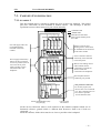
7.3. CABINETS CONFIGURATION
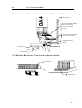
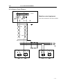
7.3.1. EXAMPLE 1
This first example shows a cabinets in which two rows of drives are mounted. The control
part (PLC and PAM) are then mounted in another cabinet. The advantage is that the
separation between control and power part is done naturally.
Unshielded Cable
Shielded Cable
ST1 25
ST1 25
ST1 25
ST1 25
Filter
Filter
Motors, resolvers and
braking resistor cables must
be shielded and are mounted
in the same conduit.
2 x Transfo
ST1 80
ST1 80
ST1 80
Filter
Filter
BA4 60
Power supply and auxiliary
filters (see the list) must be
as close as possible (max 30
cm) to the drives power
supply and their carcass
well connected to the
backpanel.
ST1 80
Drives enclosures must be
electrically well connected
to the back panel
Motors and braking resistor
cables shields must be
connected to a ground bar
which is itself well
connected to the backpanel
The backpanel must be
conducting, not painted.
The protective earth rail.
For security aspects, the
devices have to be connected
to it. This connection have to
be as short as possible.
Avoid "chained" earth.
Contactors
2 x Aux.
Transfo
I/Os and supply cables are
not shielded and are
mounted in the same
conduit.
BA4 30
Cable gland or other device
which connects shield to ground
bar on 360°
From/to sensors/actuators (I/Os)
and grid supply
From/to motors
and resolvers
All the devices enclosures must be well connected to the metallic backpanel which acts as
functional reference ground (which is different than Protective Earth even if both are
connected...).
Inside the cabinets, all the cables must be as close as possible to the backpanel.
- 37 -
User's Manual 024.8080.D
ST1
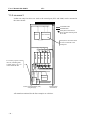
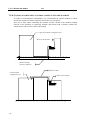
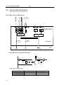
7.3.2. EXAMPLE 2
In that case only few drives are used so the control part (PLC and PAM) can be mounted in
the same cabinet.
Unshielded Cable
Shielded Cable
24VDC
PLC and PAM
Cable gland or other device
which connects shield to ground
bar on 360°
ST1 80
ST1 80
ST1 80
ST1 80
Filter
For security aspects. all the
devices (including PLC,
V24DC supply, etc.) are
connected to the PE.
Filter
BA4 60
PAM, PLC enclosures must
be well connected to the
backpanel.
Aux.
Transfo
Transfo
Contactors
From/to sensors/actuators (I/Os)
and grid supply
From/to motors
and resolvers
All remarks mentioned for the first example are valid too.
- 38 -
ST1
User's Manual 024.8080.D
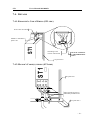
7.4. DETAILS
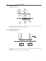
7.4.1. RESOLVER' S CABLE WIRING (ST1 SIDE)
Screws must be locked.
ST1
Metallic or metallized
plastic case
Grounding of the
resolver cable shield
DO NOT CONNECT
CABLE SHIELD TO
PIN 1!
No paint here !
ST1
7.4.2. MOTOR' S CABLE(S) WIRING (ST1 SIDE)
No paint here!
Motor thermal protection.
Individualy shielded wires
No paint here !
- 39 -
User's Manual 024.8080.D
ST1
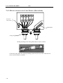
7.4.3. MOTOR AND RESOLVER CABLE WIRING (MOTOR SIDE)
Protective
earth wiring.
AMP Module
Cable gland
Shield grounding in the cable glands must be done as follow:
saa007_a.dsf / 25.11.96
If relevant, plugs with same shield grounding system must be used. The connectors on
motor side must then be metallic.
- 40 -
ST1
User's Manual 024.8080.D
BA4
7.4.4. SUPPLY' S AND BRAKING RESISTOR' S CABLE WIRING (BA4 SIDE)
No paint here !
The drives earth bar must
not be used as earth
connection for other
circuits.
Grounding of the braking
resistor cable's shield
Ground bar.
Conducting and not
painted
No paint here !
Conductive material.
No paint here !
7.4.5. BRAKING RESISTOR' S CABLE WIRING (RESISTOR SIDE)
No paint here !
No paint here !
- 41 -
User's Manual 024.8080.D
ST1
7.4.6. CONNECTION BETWEEN CONTROL CABINETS AND THE MACHINE
To improve electromagnetic compatibility, it is recommended to connect machine on which
motors are mounted to control cabinet in which drives are mounted.
This can be done either connecting the machine and the cabinet to the meshed earthing
network of the building or connecting machine and cabinet with a metallic conduit into
which motors and resolvers cables run through.
Control cabinets configured as §7.3
Motor on the machine
Meshed earthing
network conductors
Metallic conduit
Control cabinet
configured as §7.3
- 42 -
Motor in the machine
ST1
8.
User's Manual 024.8080.D
OUTLINES
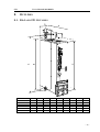
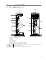
8.1. BA4 AND ST1 OUTLINES
D
E
J
C
G
B
A
F
H
STATUS
EL
SOCAP
ST1/10-310
ST1/25-310
ST1/80-310
ST1/140-310
BA4/30-50-310
BA4/60-80-310
A
332
332
420
420
332
420
B
311
311
400
400
311
400
C
283
283
371
379
283
371
D
86
86
86
174
86
86
E
18
18
18
18
18
18
F
9
9
9
9
9
9
G
88
-
H
281
281
281
285
281
281
J
13
13
13
18
13
13
- 43 -
User's Manual 024.8080.D
ST1
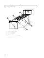
8.2. ST1 LINK AND OPTION BOARD ASSEMBLY
6
5
4
3
1
2
1 : Cover (delivered with basic module)
2 : IP20 protection set
3 : ST1 basic module
4 : Sofwtare and parameter EPROMs refer to doc. 024.8008 or 024.8068 for detailed
description)
5 : Link board L... (several types)
6 : Option board O... (several types)
- 44 -
ST1
User's Manual 024.8080.D
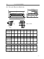
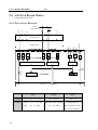
8.3. ST1 AND BA4 BOTTOM VIEW
BA4
Aux
PE
PE
PE M3 M2 M1
1~
L1
L2
L3
L'1
L'2
R1
R2
3~
ST1
7
Ground
Ground
1
2
6
3
4
4
UB (48 V)
UB
1
0V
0V
5
1
UA
UA (310 V)
2
2
3
3
1 : Power connection (DC-bus)
2 : Support
3 . Cooler
4 : Grounding strap
5 : Power board
6 : Thermal connection of the motor (X3 connector)
7 : Power connection of the motor (X2 connector)
!
In ST1/80, connector X3 ( point 6) is mounted 180° rotated, but pinout
remains the same (see §9.2).
It means that cables are compatible with every ST1.
- 45 -
User's Manual 024.8080.D
ST1
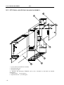
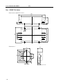
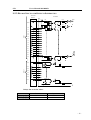
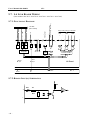
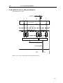
8.4. ST1 UPPER VIEW
1
2
4
5
3
1 : Resolver connection (X24)
2 : Test device connection
3 . "Reset" push-button
4 : 7-segment display
5 : Link board connectors(i.e. LIO board)
- 46 -
ST1
User's Manual 024.8080.D
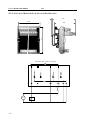
8.5. DYNAMIC BRAKING RESISTORS
B (FWTA)
L
B (FWA)
E
H
F
B (FWDA)
D
D
b
A
FWDA / FWTA
l
FWA
Type
FWA 40-150
FWA 40-200
FWA 40-300
FWA 40-400
FWA 60-300
FWA 60-400
FWA 60-500
L
200
250
350
450
350
450
550
B
60
60
60
60
80
80
80
H
85
85
85
85
116
116
116
A
180
230
330
430
330
430
530
D
30
30
30
30
40
40
40
E
154
204
304
404
304
404
504
F
23
23
23
23
23
23
23
bxl
5.5x9
5.5x9
5.5x9
5.5x9
6.5x9
6.5x9
6.5x9
Type
FWDA 40-150
FWDA 40-200
FWDA 40-300
FWDA 40-400
FWDA 60-300
FWDA 60-400
FWDA 60-500
L
200
250
350
450
350
450
550
B
130
130
130
130
180
180
180
H
85
85
85
85
116
116
116
A
180
230
330
430
330
430
530
D
60
60
60
60
90
90
90
E
154
204
304
404
304
404
504
F
23
23
23
23
23
23
23
bxl
5.5x9
5.5x9
5.5x9
5.5x9
6.5x9
6.5x9
6.5x9
Type
FWTA 40-150
FWTA 40-200
FWTA 40-300
FWTA 40-400
FWTA 60-300
FWTA 60-400
FWTA 60-500
L
200
250
350
450
350
450
550
B
190
190
190
190
270
270
270
H
85
85
85
85
116
116
116
A
180
230
330
430
330
430
530
D
120
120
120
120
180
180
180
E
154
204
304
404
304
404
504
F
23
23
23
23
23
23
23
bxl
5.5x9
5.5x9
5.5x9
5.5x9
6.5x9
6.5x9
6.5x9
Refer to the §3.2.5 for rating and to §2.6.5 for their normalized values.
- 47 -
User's Manual 024.8080.D
ST1
8.6. EMC FILTERS
FN351-25/33 and FN351-50/33:
250
17
0.75
65
200
115
135
120
20
20
21
150
6.5
sta002_a.dsf / 9.12.96
FN 2010-3-6:
24
5.3
6.3
21
64
54
44
33
9
15
sta004_a.dsf / 16.12.96
- 48 -
ST1
User's Manual 024.8080.D
9.
WIRING DIAGRAMS
9.1. POWER WIRING AND SAFETY DEVICES
24 V
CK1 3 or CK21
if two steps
powering on
is used
θ
ON
RIL : In-Rush current limitation
resistor (10 •/50W).
C1
Optional devices
REBR : Emergency brake resistor
(refer to § 3.2.7 for rating).
CK1 4
CF1
CF2
F1 : Power transformer
protection
(refer to § 3.2.4 for rating).
CF3
t = 0.3s
Security devices
RDBR : Dynamic braking resistor
(refer to § 3.2.5 for rating).
Stop 0 (Emergency Stop)
F2 : R IL protection (Imax =2.25A).
CK2 2
K1
F3 : R DBR protection
(refer to § 3.2.6 for rating).
K2
0V
3 x 400 V
CK1 2
CK2 3
F2
CK1 1
F1
RDBR
F3
3 x R IL
3 x R EBR
CF3
Stop 0
L1
L2
L3
R1
R2
Y
BA4
C1 θ
IN0
PE
ST1
M1
M2
T2
T1
T3
L1 L2 L3 PE
48V /
310V
48V /
310V
M
M3
DC Bus
To other
ST1
Two steps powering on (optional):
As soon as ON button is pressed, K2 is supplied. So CK21 (self-standing) and CK23
(supplying the transfo) are closed.
After 0.3 s, CK22 is closed, so K1 is supplied. Thus, CK11 is closed (supplying the transfo)
and CK12 is opened (disconnecting the Emergency brake resistors).
Safety devices:
As soon as a problem occurs (Stop0, Current to high in the transfo or in the Dynamic
braking resistor, temperature to high in the transfo), K1 and K2 are no longer supplied
thanks to Stop 0, C1, CF1, CF2, CF3. So the system is powered down (thanks to CK11 and
CK23) and the motors are shorted and then stopped (thanks to CK1 2).
- 49 -
User's Manual 024.8080.D
ST1
9.2. MOTOR WIRING
BAUTZ
ST1 Side
Motor
X2
SEM
...M506 M713... Terminal HD70 HD921
Motor Side
Box
Ragonot ATB
HD115 Terminal
HD142 Box2
M1
1
1
1
1
B
A
U
U
U
M2
3
2
2
2
G
B
V
V
V
M3
4
3
3
3
A
G
W
W
W
PE
2
H
H
GND
T
PE
T1
1*
Thermal
protection
X3
2*
A
5
5
4
C
C
K1
C
3
B
7
6
5
D
D
K2
D
C
4
7
E
E
B1
A
D
6
8
F
F
B2
B
Auxiliary
Brake 24VDC
1: Must have CDEPHA parameter set to 10992 (hexa: 2AAA)
2: only HD115, HD142 and BMR 190
* pin 1 is for PTC interface
pin 2 for temperature switch
For shield connection, see §7.4
9.3. RESOLVER WIRING
9.3.1. SINGLE RESOLVER WIRING
15 pins D-Sub
ST1 connector X24
Motor side
connector
BAUTZ
SEM
Ragonot ATB
HD70 Other
line 4
3
3
P
S1
5
ref. 12
4
4
D
S3
4
line 5
1
6
C
S2
7
ref. 13
2
5
E
S4
6
+ 14
5
2
B
R3
1
-
6
1
A
R1
2
12
9
J
T
9
Usin
Ucos
U1
6
For shield connection, see §7.4.
- 50 -
T3
ST1
User's Manual 024.8080.D
9.3.2. WIRING A SECOND RESOLVERS
X241
1
1
live
Usin1
4
4
12
ref. 12
5
live
5
ref.
13
13
+
14
14
-
6
6
Ucos1
X24
U1
to 1st resolver
(as fig. 8.3.1)
X242
1
2
live
2
ref.
10
live
3
3
ref.
11
11
+
15
-
7
Usin2
Ucos2
10
8
U2
4V7
4V7
to 2nd resolver
9
15
7
024.7063
adapter for 2 resolvers
- 51 -
User's Manual 024.8080.D
ST1
9.3.3. WIRING A RESOLVER AND A POTENTIOMETER
1
1
live
Usin1
4
4
12
ref. 12
live
Connector X241
5
5
Ucos1
to the resolver
(as § 8.3.1)
13
ref. 13
+
14
14
-
6
6
to the ST1
(connector X24)
U1
Connector X242
1
live
Usin2
2
2
10
ref. 10
live
3
3
ref.
11
11
+
15
-
7
Ucos2
1k
8
U2
4V7
4V7
9
15
7
024.7063
Adapter for 2 resolvers
Feeding the potentiometer via pin 9 instead of pin 14 brings better use of potentiometer
range
(0..10V).
A voltage source (i.e. CNC analog output) may be connected in the same way, using pin #
1, 2 and 10 and leaving pin # 15 (+ 15V) open. In that case, you have to know that the input
inpedance is about 5k½. It means that, by 10 V, the input current will be 2 mA.
It is also possible to wire both the resolver and the potentiometer to the ST1 using a single
plug. Refer to document 024.8068.A § 8.12.1.
- 52 -
ST1
User's Manual 024.8080.D
9.4. LPO LINK BOARD WIRING
(Part number 024.7066 / 024.7080 / 024.7082)
9.4.1. FUNCTIONAL DIAGRAM
Address
(HIGH)
Address
(LOW)
Type
(only in 024.7066)
Rx
CRC error
Carrier fail
(only in 024.7080)
1
2
Settings
Optic Fiber
H5
H6
3
Output
Input 1
4
H1
5
Reset
Input 2
Input 1
6
H2
H3
H4
7
Input 2
8
Reset
Closed = OK
LED's
Tx
+
24 VDC
(Ext. Source) -
X1
LF
LF
PAM-ring
Interface
LF
2 Inputs
"Fault"
Output
Reset
Input
LPO Board
Reset
OK
ST1
I/O-Bus
9.4.2. BINARY INPUTS SCHEMATICS
22k
2V7
1k8
56k
+
47n
2k2
-
Delays due to the RC filter:
Raising edge
Falling edge
Reset
4.2 ms
2.1 ms
Inputs
4.2 ms
2.1 ms
- 53 -
User's Manual 024.8080.D
ST1
9.5. LIO LINK BOARD WIRING
(Part number 024.7040)
9.5.1. FUNCTIONAL DIAGRAM
24 VDC
+
-
50
49 48
47 46
45
+ - +
- +
-
18
Junction module
17 16
+
OUT 7
OUT 0
IN 15
IN 1
IN 0
RESET
(external source)
15
2
1
- + -
closed = ok
Phoenix FLMK50
1
X41
LF
LF
BF
LF
-
+
2
3
Tx
+
Rx
Flat ribbon cable
4
5
6
X42
LF
16 inputs
8 outputs
UART
"Fault"
output
8K 8
EEPROM
RESET
input
LIO Board
Address selector
sequence memory
ST1
RESET
Current
Voltage
I/O-BUS
ok
Inputs
Outputs
Relay
typ. 10 mA @ 24 VDC
max. 100 mA
max.2 A
admissible when "open":
cutting capacity:
HIGH
+19..+30 VDC
LOW
-16..+5 VDC
-0.3..+43 VDC
DC: 150 VDC/35 W
AC: 125 VRMS/60 VA
- 54 -
ST1
User's Manual 024.8080.D
9.5.2. BINARY INPUTS AND OUTPUTS SCHEMATICS
JUNCTION
MODULE
LIO BOARD
X41
+
50
49
IN1
IN2
INPUT
S
IN3
IN4
IN5
IN6
IN7
IN8
IN9
IN10
IN11
IN12
IN13
47
46
44
42
40
38
36
34
32
30
45
43
41
+
+
+
+
39
37
35
+
+
+
33
21
29
+
+
+
28
27
26
25
+
+
24
23
+
22
21
20
IN14
-
49
1k0
19
18
+
+
RESET
100k
4k7
4k7
10n
47k
+
48
IN0
12V
-
4k7
10n
TO / FROM
SEQUENCER
RESET
50
IN15
17
+
16
OUT0
OUT1
OUTPUT
S
OUT2
OUT3
OUT4
-
15
14
12
10
8
+
13
+
11
+
9
+
7
+
6
5
OUT5
4
OUT6
3
+
BSX47-10
+
2
OUT7
-
-
1
P6KE51
A
10k
Delays due to the RC filter:
Raising edge
Falling edge
Reset
1.2 ms
0.8 ms
Inputs
0.6 ms
0.4 ms
- 55 -
User's Manual 024.8080.D
ST1
9.5.3. JUNCTION MODULE OUTLINES AND SCHEMATICS
2,5
63
135
77
58
Flat ribbon cable to OIO or LIO board
+
24 V
_
- 56 -
1
2
1
2
49
49
50
50
-
-
ST1
User's Manual 024.8080.D
9.5.4. SERIAL LINK WIRING
+
-
24VDC
Machine control equipment
With active transmission and active reception
20mA
20mA
TXD
RXD
+
Rx
1
2
ST1
+
3
+
Tx
4
LIO
+
X42
Rx
1
2
ST1
+
3
+
Tx
4
X42
LIO
- 57 -
User's Manual 024.8080.D
ST1
9.6. LS LINK BOARD WIRING
(Part number 024.7025 / 024.7026)
9.6.1. FUNCTIONAL DIAGRAM
+
+ +
10
11 12
-
Closed = ok
IN 1
IN 0
RESET
- 24 VDC
(Ext. source)
+ 13 14
15
8
Rx
Tx
9
X42
See fig of § 8.6.3
and 8.6.4 for details.
LF
LF
LF
2 Inputs
UART
"Fault"
output
RESET
input
I/O-BUS
ok
RESET
LS Board
9.6.2. BINARY INPUTS SCHEMATICS
12V
4k7
47k
1k
+
(Reset
100k)
10n
4k7
(Reset
100n)
-
Delay due to the RC filter:
Raising edge
Falling edge
- 58 -
Reset
12 ms
8.2 ms
Inputs
0.6 ms
0.4 ms
ST1
ST1
User's Manual 024.8080.D
9.6.3. RS485 SERIAL LINK
11
Tx
Rx
(Part number 024.7025)
3
10
9
2
7
X41
GND
Each line pair (TXD and RXD) must be "terminated" by a 100½ resistor ( to be mounted
within plugs at both cable and on the receiver side)
9.6.4. MA (TTY) SERIAL LINK
(Part number 024.7026)
+
ST1
2
+
3
Rx
6
X42
7
Tx
In that case, The same connector (X42) is used for the serial link and for the direct inputs
and outputs.
Refer to §8.5.2 for "chaining" several ST1 on a single line.
- 59 -
User's Manual 024.8080.D
ST1
9.7. LA LINK BOARD WIRING
(Part number 024.7015 / 024.7018 / 024.7019 / 024.7021 / 024.7106)
IN 2
Closed = ok
- +
3 4
- +
5 6
11 12
RESET
-
+
1 2
24 VDC
(Ext. source)
IN 1
-
+
13 14 15
Analog input
+
16
-
17
Second analog input
(only in LA2 p.n. 024.7021)
9.7.1. FUNCTIONAL DIAGRAM
Only in LA5 (LAC) p.n. 024.7106
Ua1
+
18
-
19
Ua2
-
+
1
2
3
Ua0
-
+
4
-
+
5
6
LF
LF
2 Inputs
4k7
LF
4k7
X41
+15V 0V -15V
+
A
-
#
+
A
X43
-
Encoder simulator
#
"Fault"
output
RESET
input
ST1
I/O-BUS
ok
RESET
LA Board
9.7.2. BINARY INPUT(S) SCHEMATICS
4k7
12V
1k
+
4k7
-
- 60 -
ST1
User's Manual 024.8080.D
9.7.3. ANALOG INPUT SCHEMATICS
1k8
8k2
10k
+
1n
1n
1k8
-
8k2
+
1n
10k
1n
- 61 -
User's Manual 024.8080.D
ST1
9.8. OM AND OS OPTIONAL BOARD WIRING
OM
OS
OS
LIO
LIO
LIO
ST1 "master"
ST1 "slaves"
Refer to document 024.8034 for optic fiber cable confection.
- 62 -
ST1
User's Manual 024.8080.D
9.9. OEI OPTIONAL BOARD WIRING
(Part number 024.7045)
9.9.1. WIRING DIAGRAM
0V_1
9
8
Filter
+5V (Out)
10
7
6
0V_1
5
+5V_1
Ua1
11
Ua1
12
Ua2
13
Ua2
14
0V (Out)
15
Ua0
X61
Ua0
ENCODER
Encoder connector (X61):
4
3
2
1
Filter
Ua2
Ua0
Filter
Ua1
"Power" connector (X62):
5VDC
External supply
+24V
0V
+
-
Converter
OUT
IN
Filter
Reference enable
6
10
7
8
9
11
12
X62
0V_1
5
+5V_1
0V
4
0V_1
+5V
3
+5V_1
2
{
{
1
+
OUT
+
IN -
DC/DC converter
(Option)
- 63 -
User's Manual 024.8080.D
ST1
9.9.2. INCREMENTAL INPUT TYPES
The OEI Option Board is available in 3 different hardware versions depending on the
application, and more particularly the kind of incremental input it has to interface.
Actually, the only difference resides within a programmable IC and can also be checked
reading the tag on it.
Part Number
Typical Use
(PAL tag)
Input Signals at X61
Counting Up
Resolution
Counting Down
024.7111 =
old 024.7045
("Filtre V2")
Incremental Encoder
(quadrature signals)
4 x Line Count
024.7112
Step-Motor Input
(1 pulse and 1 direction
input)
4 x Line Count
Step-Motor Input
(1 input for pulses up and
1 for pulses down)
2 x Line Count
("Filtre V3")
024.7113
("Filtre V4")
- 64 -
ST1
User's Manual 024.8080.D
9.10. OIO OPTIONAL BOARD WIRING
(Part number 024.7047)
24 VDC
+
-
48
47 46
45
+
- +
-
Junction module
OUT 15
OUT 8
IN 31
IN 17
IN 16
(external source)
18
17
+
- +
16
15
-
18
17 16
15
2
1
2
1
Phoenix FLMK50
ribbon cable
48
47 46
45
X41
LF
LF
LF
16 inputs
8 outputs
OIO BOARD
ST1
I/O-BUS
Refer to § 8.5 (LIO Link Board) for detailed schematics.
- 65 -