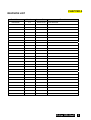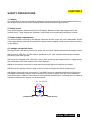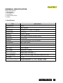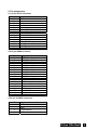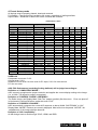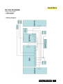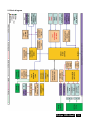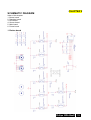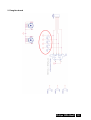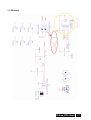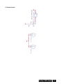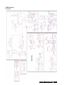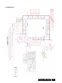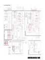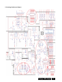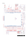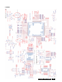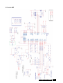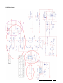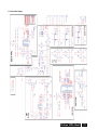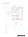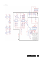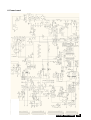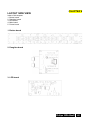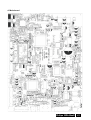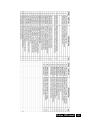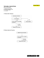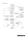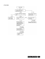
1
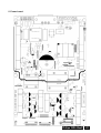
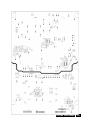
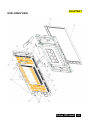
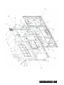
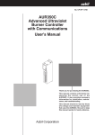
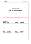
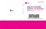
SERVICE MANUAL
Philips
BDL46xxE
CONTENT
CHAPTER A REVISION LIST……………………………………………………………………….2
CHAPTER B WARNNING…………………………………………………………………………...3
CHAPTER C SEFETY RRECAUTIONS………….……………………......................................4
CHAPTER 1 GENERAL SPECIFICATION…………………..............................................5 - 10
CHAPTER 2 OPEARTING INSTRUCTION…………………………….............................11 - 13
CHAPTER 3 THEORY OF OPERATION……………………………................................14 - 16
CHAPTER 4 BLOCK DIAGRAM…………………………………….….............................17 - 18
CHAPTER 5 SCHEMATIC DIAGRAM…………………...................................................19 - 39
CHAPTER 6 LAYOUT SIDE VIEW……………………....................................................40 - 43
CHAPTER 7 EXPLODED VIEW…………………………………………............................44 - 46
CHAPTER 8 TROUBLE SHOOTING…………………….…………..................................47 - 49
Philips BDL46xxE
1
CHAPTER A
REVISION LIST
Model Name
Version
Issues Date
BDL46xxE
1.0
2009-12-26
Remark
First Release
Philips BDL46xxE
2
CHAPTER B
WARNNING
This service information is designed for experienced repair technicians only and is not
designed for use by the general public.
It does not contain warnings or cautions to advise non-technical individuals of
potential dangers in attempting to service a product.
Products powered by electricity should be serviced or repaired only by experienced
professional technicians.
Any attempt to service or repair the product or products dealt within this service
information by anyone else could result in serious injury or death.
Philips BDL46xxE
3
CHAPTER C
SAFETY PRECAUTIONS
1. Caution
No modification of any circuit should be attempted. Service work should only be performed after you
are through familiar with all of the following safety checks and servicing guide lines.
2. Safety check
Care should be taken while servicing this LCD display. Because of the high voltage used in the
inverter circuit. These voltage are exposed in such areas as the associated transformer circuits.
3. Power supply requirements
The external power converter for this display utilizes AC and DC cords, AC cord is detachable, but DC
cord is permanently attached. Any attempt to replace another adapter could result in serious problem
on the display.
4. Leakage current hot check
4-1 Plug the AC cord directly into the AC outlet. Do not use an isolation transformer during this check.
4-2 Connect a 1500 ohm, 10 watt resistor, paralleled by a 0.15uF capacitor between each metallic
part and a good earth ground.
4-3 Use an AC voltmeter with 1000 ohm / volt or more sensitivity and measure the AC voltage across
the combination 1500 ohm resistor and 0.15uF capacitor.
4-4 Move the resistor connection to each exposed metallic part and measure the voltage.
4-5 Reverse the polarity of the AC plug in the AC outlet and repeat the above measurement.
4-6 Voltage measured must not exceed 1.5 volt RMS, from any exposed metallic part to the ground.
A leakage current tester may be used in the above hot check, in which case any circuit measured
must not exceed 1 milliamp. In the case of a measurement exceeding the 1 milliamp value, a rework is
required to eliminate the chance of a shock hazard.
AC VOLTMETER
V
0.15u
.
To Metal Parts
1500
10W
Earth Ground
Philips BDL46xxE
4
CHAPTER 1
GENERAL SPECIFICATION
Index of this chapter:
1. Specification
2. Pin assignment
3. Connection
4. Preset factory mode
5. Outline
1. Specification
Item
Specification
LCD panel size
46 inch
DCR
4000:1 (typical)
Viewing angle
Horizontal 178°, vertical 178° (typical)
Response time
8 ms (GTG)
Brightness
450 cd/m2 (typical)
Input signal
D-sub, HDMI, S-VEDIO, RS-232C, Audio
Display color
16.7 M colors
Frequency
31-91 kHz Horizontal, 50-75 Hz Vertical
Max resolution
1920 x 1080 (60Hz)
Max Pixel clock
165 MHZ
Tilt
0°
Audio output
Without Speaker
Power supply
100-240VAC, 50-60Hz
Power consumption
Display mode: Max 285W
Sleeping mode: Less than 1W
Size (w/o packing)
Width: 1122.0 mm, Height: 704.6 mm, Depth: 405.1 mm
Net Weight
31.1 kg
Environmental conditions
Operating temperature: 5 ~ 40°C, Humidity: 20-80%
Storage temperature: -20 ~ 60°C, Humidity: 10-90%
Philips BDL46xxE
5
2. Pin assignment
2.1 15-pin D-sub connector
PIN
1
2
3
4
5
6
7
8
9
10
11
12
13
14
15
Signal
Red
Green
Blue
No Pin
Ground
Ground Red
Ground Green
Ground Blue
+5 V for DDC
Ground
Ground
SDA (DDC Data)
H – Sync
V – Sync
SCL (DDC Clock)
2.2 19-pin HDMI connector
PIN
1
2
3
4
5
6
7
8
9
10
11
12
13
14
15
16
17
18
19
Signal
TMDS Data2+
TMDS Data2 Shield
TMDS Data2TMDS Data1+
TMDS Data1 Shield
TMDS Data1TMDS Data0+
TMDS Data0 Shield
TMDS Data0TMDS Clock+
TMDS Clock Shield
TMDS ClockCEC
Reserved (N.C. on device)
SCL
SDA
DDC/CEC Ground
+5V Power
Hot Plug Detect
2.3 4-pin S-VIDEO connector
PIN
1
2
3
4
Signal
GND
GND
Y (Luminance)
C (Chroma)
Philips BDL46xxE
6
2.4 9-pin RS-232C connector
PIN
1
2
3
4
5
6
7
8
9
Signal
NC
RXD
TXD
NC
GND
NC
RTS
CTS
NC
3. Connection
AUDIO IN 1, 2, 3
To input audio signal from external equipment such as a computer VCR or DVD player.
AUDIO OUT
To output the audio signal from the AUDIO IN 1, 2 and 3 jack.
EXTERNAL CONTROL (mini D-sub 9 pin)
Connect the IN connector with the RS-232C OUT connector of the computer or a multi-connected
BDL46xxE monitor. Connect the OUT connector with the RS-232C IN connector of BDL46xxE
monitor.
VIDEO IN/OUT
VIDEO IN connector(BNC and RCA): To input a composite video signal. BNC and RCA are not
available at the same time.(Use only one input).
VIDEO OUT connector(BNC): To output the composite video signal from VIDEO IN connector.
S-VIDEO IN connector(Mini din 4 pin): To input the S-video (Y/C separate signal).
EXTERNAL SPEAKER TERMINAL
To output the audio signal from external speakers from AUDIO 1, 2, 3 jack or HDMI.
AC IN connector
Connectors with the supplied power cord.
RGB 1 IN(HDMI 1)
To input digital RGB signals from a computer.
* This connector does not supports analog input. AUDIO is supported via HDMI.
RGB 2 IN(HDMI 2)
To input digital RGB signals from computer.
* This connector does not support analog input. AUDIO is supported via HDMI.
RGB 3 IN(mini D-sub 15 pin)
To input a analog RGB signals from a computer or other RGB equipment.
RGB OUT (mini D-sub 15 pin)
To output the signal from RGB 3 N or 4 IN.
DVD/HD IN(Y, Pb/Cb, Pr/Cr)(BNC)
Connecting equipment such as a DVD player, HDTV device, or laser disc player.
Philips BDL46xxE
7
4. Preset factory mode
All timings must be properly phased, sized and centered.
Full-Screen = The input timing is scaled to full screen, regardless of scaling artefacts
Aspect Ratio = Resolution to which the native is scaled and centered
COMPATIBILITY TABLE
Mode
Standard
VESA
VESA
VESA
Resolution
640x480 @ 60Hz
640x480 @ 72Hz
640x480 @ 75Hz
720x400 @ 70Hz
VESA
800x600 @ 60Hz
VESA
1024x768 @ 60Hz
1280 x 720 @ 60Hz
PD40
1280 x 768 @ 60Hz
VESA(M9) 1280 x 768 @ 60Hz
VESA
1280x1024 @ 60Hz
M9
1360 x 768 @ 60Hz
VESA
1360 x 768 @ 60Hz
VESA
1600x1200 @ 60Hz
M9
1920x1080 @ 50Hz
SMPTE
1920x1080 @ 60Hz
1920x1080 @ 60Hz
PAL
576I(50Hz)
NTSC
480I(60Hz)
DVD
480p(60Hz)
480i(60Hz)
720p(50Hz)
720p(60Hz)
1080i (50Hz)
1080i (60Hz)
Aspect Ratio Handling
Full-Screen Aspect Ratio Composite SVHS YPBPR RGB
1920x 1080
16:9
N
N
N
Y
1920x 1080
16:9
N
N
N
Y
1920x 1080
16:9
N
N
N
Y
1920x 1080
16:9
N
N
N
Y
1920x 1080
16:9
N
N
N
Y
1920x 1080
16:9
N
N
N
Y
1920x 1080
16:9
N
N
N
Y
1920x 1080
16:9
N
N
N
Y
1920x 1080
16:9
N
N
N
Y
1920x 1080
16:9
N
N
N
Y
1920x 1080
16:9
N
N
N
Y
1920x 1080
16:9
N
N
N
Y
1920x 1080
16:9
N
N
N
Y
1920x 1080
16:9
N
N
N
Y
1920x 1080
16:9
N
N
N
Y
1920x 1080
16:9
N
N
N
Y
1920x 1080
16:9
1920x 1080
16:9
1920x 1080
16:9
1920x 1080
16:9
1920x 1080
16:9
1920x 1080
16:9
1920x 1080
16:9
1920x 1080
16:9
HDMI
Y
Y
Y
Y
Y
Y
Y
Y
Y
Y
Y
Y
Y
Y
Y
Y
OVERCAN
Component over scan: 5~8%
AV over scan: 5~9%
HDMI/DVI-D over scan: No over scan for PC input, 5~9% for video source.
PC: No over scan
ASIC FOS Performance (excluding Scaling Artifacts) will be judged according to:
Definition of “COMPATIBLE MODE”:
ASIC correctly recognizes the proper resolution and applies the correct display scaling to the image.
(I.e. a 1280 x 720 signal is properly recognized)
Definition of “PROPERLY SIZED / CENTERED”:
The Entire Image (use Display Mate “Side Tics” pattern) perfectly fits the screen. Even one pixel off
in Horizontal or Vertical Direction, makes this area “FAIL”.
Definition of “PROPERLY PHASED”:
ASIC automatically computes the correct A/D response so that a Win98 “SHUTDOWN” or “ALL”
Display Mate “MOIRE” Patterns are correctly displayed. Most critical on the panels “NATIVE”; No
‘unstableness’ of the image shall be observed.
Definition of “HD Compatibility”:
All HD timings have to work through YPbPr, HDMI, and RGB.
Philips BDL46xxE
8
5. Outline
5.1 Front view
5.2 Rear view
Philips BDL46xxE
9
5.3 Side view
5.4 Top view
Philips BDL46xxE
10
CHAPTER 2
OPEARTING INSTRUCTIONS
Index of this chapter:
1. Front-panel controls
2. OSD menu
1. Front-panel controls
All keys are located at the right edge of the display bezel.
EXET
INPUT
MUTE
The following front panel controls are available for this product.
EXIT: Located at the right edge of the display that serves as a dual function switch. It is used to exit
the menu if the OSD is on. When the OSD is off, it functions as an Aspect Ratio Control.
CHANNEL ▲/▼: Navigate through OSD depending on mode.
VOLUME +/-: Change Volume or navigate through OSD depending on mode.
INPUT: Select input from PC, HDMI, component, composite.
MUTE: Switch audio on/off.
POWER
: It is a soft power switch and not a main disconnection device. Main disconnection shall
be accomplished by physically removing the power cord from the display.
Function
Enter Factory Mode
Enter Factory Reset
Lock Front button
Reload Color Temperature
Status
AC Power Off
Standby Mode
On Mode
Power saving (when no OSD)
Schedule Standby
Fan defect mode
Factory mode
Combination Key
▲
▼
v
v
-
+
v
v
v
OFF
ON
OFF
ON
ON
Blinking(500mSec)
OFF
v
v
v
LED Control
LED Red
MUTE
v
LED Green
OFF
OFF
ON
ON
Blinking(500mSec)
Depends on SET condition
ON
* Note: Panel performance characteristics “ MUST BE” met in all display modes/inputs at standard test
conditions.
Philips BDL46xxE
11
2. OSD menu
All audio/video and other output controls shall be performed by using an On Screen Display (OSD) via
a Remote Control Unit in conjunction with the front panel controls. The following tables list the OSD
functions supported by BDL46xxE.
Level 1
PICTURE
Level 2
Level 3
BRIGHTNESS
0-100
CONTRAST
0-100
SHARPNESS
0-100
BLACK LEVEL
0-100
NOISE REDUCTION
OFF/ LOW/ MIDDLE/ HIGH
TINT
(Input: HDMI-Video timing,
0-100
DVI-D(HD timing), CVI, VIDEO
only)
COLOR
(Input: HDMI-Video timing,
0-100
DVI-D(HD timing), CVI, VIDEO
only)
5000K/ 6500K/ 7500K/ 9300K/ 10000K/ 11000K/
COLOR TEMPERATURE
USER
COLOR CONTROL
RED: 0-255
GREEN: 0-255
BLUE: 0-255
PICTURE RESET
NO/ YES
SCREEN
H-POSITON
0-100
V-POSITION
0-100
CLOCK
0-100
(Input: PC-A only)
CLOCK PHASE
0-100
(Input: PC-A only)
PC: FULL/ NORMAL/ CUSTOM/ REAL(OFF)
ZOOM MODE
VIDEO: FULL/ NORMAL/ DYNAMIC/ CUSTOM/
REAL(OFF)
CUSTOM ZOOM
ZOOM
H ZOOM
V ZOOM
H POSTION
V POSTION
SCREEN RESET
NO/YES
AUDIO
BALANCE
0-100
TREBLE
0-100
BASS
0-100
AUDIO RESET
NO/YES
PIP
PIP SIZE
LARGE/ MIDDLE/ SMALL
PIP AUDIO
MAIN/ SUB
PIP RESET
NO/ YES
AUTO ADJUST
CONFIGURATION1
(Input: PC-A only)
RGB: ON/ OFF
POWER SAVE
VIDEO: ON/ OFF
ENGLISH/ FRENCH/ GERMAN/ SPANISH/
LANGUAGE
RUSSIAN/ ITALIAN/ POLISH/ TURKISH/
SIMPLIFY CHINESE
PANEL SAVING
COOLING FAN: ON/ AUTO
BRIGHTNESS: ON/ OFF
PIXEL SHIFT: OFF/ 10-999sec
COLOR SYSTEM
AUTO/ NTSC/ PAL/ SECAM/ 4.43NTSC/ PAL-60
(Input: VIDEO only)
CONFIGURATION RESET
NO/ YES
FACTORY RESET
NO/ YES
CONFIGURATION2 OSD TURN OFF
OSD TURN OFF
INFORMATION OSD
ON(1-10sec)/ OFF
Philips BDL46xxE
12
SLEEP TIMER
OSD H-POSITION
OSD V-POSITION
MONITOR INFORMATION
ADVANCED OPTION
ON(1-24Hour)/ OFF
0-100
0-100
MODEL NAME
SERIAL NO
OPERATION HOURS
SW VERSION
INPUT RESOLUTION
(Input: PC-A only)
BLACK LEVEL EXPANSION
High/ Middle/ Low/ OFF
(Input: VIDEO only)
GAMMA SELECTION
2.2/2.4/ S GAMMA/ NATIVE
SCAN MODE
(Input: HDMI-Video timing,
OVER SCAN/ UNDER SCAN
DVI-D(HD timing), CVI, VIDEO
only)
SCAN CONVERSION
PROGRESSIVE/ INTERLACE
FILM MODE
AUTO/ OFF
(Input: CVI, VIDEO only)
IR CONTROL
NORMAL/ LOCK/ PRIMARY/ SECONDARY
KEYBOAR CONTROL
NO/ YES
TILING
H MONITORS
V MONITORS
POSITION
FRAME COMP
ENABLE
DATE AND TIME
YEAR
MONTH
DAY
HOUR
MINUTE
DAYLIGHT SAVING
CURRENT DATE TIME
SCHEDULE
ITEM
ON TIME
HOUR:MINUTE
OFF TIME
HOUR:MINUTE
INPUT
EVERYDAY
MON
TUE
WED
TUR
FRI
SAT
SUN
EVERYWEEK
MONITOR ID
DDC/CI
ON/ OFF
HEAT STATUS
SMART POWER
OFF(LOW)/ MEDIUM/ HIGH
ADVANCED OPTION RESET NO/ YES
Philips BDL46xxE
13
CHAPTER 3
THEORY OF OPERATION
Index of this chapter:
1. Mstar MST5251A scaler
2. NECuPD64015 Video Decoder
3. TI PCM1753 Audio DAC
4. JRC NJW1141 Audio Processor
5. Winbond W79E659 MCU
6. Fintek F75101R GPIO Expander
7. Eon EN29F040A 4MBit Flash
8. YAMAHA YDA138 Audio Amplifier
9. Sipex SP3243 RS232 Transceiver
10. Mitsumi MM1671 Low Supply Voltage 75 Ohm Driver
11. EtronTech EM636165TS-5G SDRAM
12. National Semiconductor LM1881 Video Sync Separator NXP PCF8563 RTC
13. NXP PCF8563 RTC
14. ST TSH340 Video Buffer Pericom PI5C3253 Dual 1-of-4 FET Multiplexer / Demultiplexer
15. Pericom PI5C3253 Dual 1-of-4 FET
16. ESMT M13S128324A DDR SDRAM
17. ATMEL AT24C64AN EPROM
1. Mstar MST5251A scaler
The MST5251A is a high performance and fully integrated graphics processing ICsolution for
multi-function LCD monitor/TV with resolutions up to UXGA/WUXGA. It is configured with an
integrated triple-ADC/PLL, an integrated DVI/HDCP/HDMI receiver, two video de-interlacers, two high
quality scaling engines, an on-screen display controller, and abuilt-in output clock generator. By use of
external frame buffer, PIP/POP is provided for multimedia applications. It supports de-interlaced
full-screen video, video-on-graphic overlay, split screen, frame rate conversion, and aspect ratio
conversion for various video sources. To further reduce system costs, the MST5251A also integrates
intelligent power management control capability for green-mode requirements and spread spectrum
support for EMI management.
2. NEC uPD64015 Video Decoder
The uPD64015 is a video decoder LSI with an on-chip three-dimensional Y/C separation function that
supports NTSC-M and PAL-BDGHI composite signals and a three-dimensional noise reduction
function that supports all input signals. It includes four high-accuracy A/D converter channels for
analog video input, an anti-alias filter, Y/C separation, chroma decoding supporting
NTSC/PAL/SECAM, three-dimensional noise reduction supporting all input signals, and various
definition correction functions, and supports digital color difference output. The uPD64015
incorporates a 3-ch DAC and can output decoded video signals or signals output from the
incorporated SG (Signal Generator), in the form of RGB or analog color-difference signals.
3. TI PCM1753 Audio DAC
The PCM1753/54/55 is a CMOS, monolithic, integrated circuit, which includes stereo digital-to-analog
converters and upport circuitry in a small 16-lead SSOP package. The data converters use TI's
enhanced multilevel delta-sigma architecture, which employs 4th-order noise shaping and 8-level
amplitude quantization to achieve excellent dynamic performance and improved tolerance to clock
jitter. The PCM1753/54/55 accepts industry standard audio data formats with 16- to 24-bit data,
providing easy interfacing to audio DSP and decoder chips. Sampling rates up to 200 kHz are
supported. A full set of user programmable functions is accessible through a three-wire serial control
port, which supports register write functions.
4. JRC NJW1141 Audio Processor
The NJW1141 is a sound processor includes all of the functions required to process the audio signal
for TV, such as tone control, balance, volume, mute, and AGC functions. All of the internal status and
Philips BDL46xxE
14
variables are controlled by I2C BUS Interface.
5. Winbond W79E659 MCU
The W79E659 is a fast, 8051/52-compatible microcontroller with a redesigned processor core that
eliminates wasted clock and memory cycles. Typically, the W79E659 executes instructions 1.5 to 3
times faster than that of the traditional 8051/52, depending on the type of instruction, and the overall
performance is about 2.5 times better at the same crystal speed. As a result, with the fully-static
CMOS design, the W79E659 can accomplish the same throughput with a lower clock speed, reducing
power consumption. The W79E659 provides 256 bytes of on-chip RAM; 1-KB of auxiliary RAM; seven
8-bit, bi-directional and bit-addressable I/O ports; an additional 4-bit port P4; three 16-bit
timer/counters; an UART serial port, 2 channels of I2C with master/slave capability and 8 channels of
10-bit ADC. These peripherals are all supported by ten interrupt sources with 2 levels of priority. The
W79E659 contains a 32-KB Flash EPROM whose contents may be updated in-system by a loader
program stored in an auxiliary, 4-KB Flash EPROM. Once the contents are confirmed, it can be
protected for security.
6. Fintek F75101R GPIO Expander
The F75101R is a multifunctional general purpose IO chip providing 16 GPIO powered by 3VSB by
power on setting. Level or pulse modes can be programmed by registers. With 2 sets of watchdog
timer, F75101R provides more flexible control for system.
7. Eon EN29F040A 4MBit Flash
The EN29F040A is a 4-Megabit, electrically erasable, ead / write non-volatile flash memory. organized
into 512K ords with 8 bits per word, the 4M of memory is arranged in eight uniform sectors of
64Kbytes each. Any byte can be programmed typically in 10µs. The EN29F040A features 5.0V
voltage read and write operation, with access times as fast as 45ns to eliminate the need for WAIT
states in high-performance microprocessor systems.
8. YAMAHA YDA138 Audio Amplifier
YDA138 (D-3) is a high efficient digital audio power amplifier IC that operates with a single 12V power
supply. An audio power amplifier with a maximum output of 10W (RL=8 ) 2ch can be configured with
one chip. YDA138 has a “Pure Pulse Direct Speaker Drive Circuit” which directly drives speakers
while reducing distortion of pulse output signal and reducing noise on the signal, and realizes the
highest standard low distortion rate characteristics and low noise characteristics as 10W-class of
output digital amplifier IC. In addition, circuit design with fewer external parts can be made depend on
the condition of use because corresponds to filter less. YDA138 provides Overcurrent protection
function for speaker output terminals, IC thermal protection function, POP noise reduction function,
and AM interference measures function as well as power-down function and output mute function.
9. Sipex SP3243 RS-232 transceiver
The SP3243 transceivers meet the EIA/TIA-232 and ITU-T V.28/V.24 communication protocols.
generate 5.5V RS-232 voltage levels from a single +3.0V to +5.5V power supply and operate at a data
rate of 120kbps fully loaded. The SP3243 devices feature ٛ circuitry automatically wakes up from . It
occurs after a RS-232 cable being disconnected. Under this condition, the internal charge pump and
the drivers will be shut down. Otherwise, the system automatically comes online.
10. Mitsumi MM1671 Low Supply Voltage 75 Ohm Driver
This IC is a 75Ω driver with a built-in LPF that can operate at low voltage. It supports 3V and 5V
operating power voltage, and is ideal for video signal output in devices ranging from portable digital
still cameras to stationary equipment such as DVD players. It incorporates a high performance
4-stage LPF, which is ideal for removing DAC sampling noise. In addition, ultra-low current
consumption has been achieved b of the batteries in portable devices. The built-in amp gain on this IC
is available in series: 6dB/9dB/12dB/16.5dB, thus enabling support for DAC and a variety of output
amplitudes. There is also a series with input clamp and one without, allowing support for a range of
video signals, not just composite signals.
11. EtronTech EM636165TS-5G SDRAM
The EM636165 SDRAM is a high-speed CMOS synchronous DRAM containing 16 Mbits. It is
Philips BDL46xxE
15
internally configured as a dual 512K word x 16 DRAM with a synchronous interface (all signals are
registered on the positive edge of the clock signal, CLK). Each of the 512K x 16 bit banks is organized
as 2048 rows by 256 columns by 16 bits. Read and write accesses to the SDRAM are burst oriented;
accesses start at a selected location and continue for a programmed number of locations in a
programmed sequence. Accesses begin with the registration of a BankActivate command which is
then followed by a Read or Write command. The EM636165 provides for programmable Read or Write
burst lengths of 1, 2, 4, 8, or full page, with a burst termination option. An auto precharge function may
be enabled to provide a self-timed row precharge that is initiated at the end of the burst sequence. The
refresh functions, either Auto or Self Refresh are easy to use. By having a programmable mode
register, the system can choose the most suitable modes to maximize its performance. These devices
are well suited for applications requiring high memory bandwidth and particularly well suited to high
performance PC applications.
12. National Semiconductor LM1881 Video Sync Separator
The LM1881 Video sync separator extracts timing information including composite and vertical sync,
burst/back porch timing, and odd/even field information from standard negative going sync NTSC,
PAL*, and SECAM video signals with amplitude from 0.5V to 2V p-p. The integrated circuit is also
capable of providing sync separation for non-standard, faster horizontal rate video signals. The
vertical output is produced on the rising edge of the first serration in the vertical sync period. A default
vertical output is produced after a time delay if the rising edge mentioned above does not occur within
the externally set delay period, such as might be the case for a non-standard video signal.
13. NXP PCF8563 RTC
The PCF8563 is a CMOS real-time clock/calendar optimized for low power consumption. A
programmable clock output, interrupt output and voltage-low detector are also provided. All address
and data are transferred serially via a two-line bidirectional I2C-bus. Maximum bus speed is 400
kbits/s. The built-in word address register is incremented automatically after each written or read data
byte.
14. ST TSH340 Video Buffer
The TSH340 is a video buffer featuring a gain of 6dB. A large bandwidth of 300MHz for only 9.4mA of
quiescent current allows the TSH340 to achieve a gain flatness of 220MHz. Its structure features a
very high slew rate of 540V/µs minimum guaranteed by test. Associated to a very good THD these
characteristics are particularly intended in the high quality video systems. The TSH340 is available in
tiny SOT23-5 and SO8 plastic packages for size saving consideration.
15. Pericom PI5C3253 Dual 1-of-4 FET Multiplexer / Demultiplexer
Pericom Semiconductor's PI5C3253 is a Dual 4:1 Multiplexer / demultiplexer with three-state outputs
that is pinout compatible with the PI74FCT253T, 74F253, and 74ALS/AS/LS 253. Inputs can be
connected to outputs with low on resistance (5Ω) with no additional ground bounce noise or
propagation delay.
16. ESMT M13S128324A DDR SDRAM
17. ATMEL AT24C64AN EPROM
The AT24C32A/64A provides 32,768/65,536 bits of serial electrically erasable and programmable
read only memory (EEPROM) organized as 4096/8192 words of 8 bits each. The device's cascadable
feature allows up to 8 devices to share a common twowire bus. The device is optimized for use in
many industrial and commercial applications where low power and low voltage operation are essential.
The AT24C32A/64A is available in space saving 8-lead JEDEC PDIP, 8-lead JEDEC SOIC, 8-lead
EIAJ SOIC, 8-lead Mini-MAP (MLP 2x3) and 8-lead TSSOP packages and is accessed via a 2-wire
serial interface. In addition, the entire family is available in 2.7V (2.7V to 5.5V) and 1.8V (1.8V to 5.5V)
versions.
Philips BDL46xxE
16
CHAPTER 4
BLOCK DIAGRAM
Index of this chapter:
1. Wiring diagram
2. Block diagram
1. Wiring diagram
Philips BDL46xxE
17
2. Block diagram
Philips BDL46xxE
18
CHAPTER 5
SCHEMATIC DIAGRAM
Index of this chapter:
1. Button board
2. Daughter board
3. LED board
4. Sensor board
5. Main board
6. Power board
1. Button board
Philips BDL46xxE
19
2. Daughter board
Philips BDL46xxE
20
3. LED board
Philips BDL46xxE
21
4. Sensor board
Philips BDL46xxE
22
5. Main board
5.1 Power
Philips BDL46xxE
23
5.2 HDMI Input
Philips BDL46xxE
24
5.3 HDMI Switch
Philips BDL46xxE
25
5.4 Analog Input
Philips BDL46xxE
26
5.5 Analog Switch and Outpot
Philips BDL46xxE
27
5.6 Scaler
Philips BDL46xxE
28
5.7 DDR-SDRAM
Philips BDL46xxE
29
5.8 MCU
Philips BDL46xxE
30
5.9 FAN Control & RTC
Philips BDL46xxE
31
5.10 Panel Interface
Philips BDL46xxE
32
5.11 Audio AMP
Philips BDL46xxE
33
5.12 Video Input
Philips BDL46xxE
34
5.13 Audio Input
Philips BDL46xxE
35
5.14 Video Decoder
Philips BDL46xxE
36
5.15 Video Decoder SDRAM
Philips BDL46xxE
37
5.16 RS232
Philips BDL46xxE
38
6. Power board
Philips BDL46xxE
39
CHAPTER 6
LAYOUT SIDE VIEW
Index of this chapter:
1. Button board
2. Daughter board
3. LED board
4. Main board
5. Power board
1. Button board
2. Daughter board
3. LED board
Philips BDL46xxE
40
4. Main board
Philips BDL46xxE
41
5. Power board
Philips BDL46xxE
42
Philips BDL46xxE
43
CHAPTER 7
EXPLODED VIEW
Philips BDL46xxE
44
Philips BDL46xxE
45
Philips BDL46xxE
46
CHAPTER 8
TROUBLE SHOOTING
Index of this chapter:
1. Remote No Function
2. Button key No Function
3. No Image appear
4. No Audio
1. Remote No Function
2. Button Key No Function
Philips BDL46xxE
47
3. No Image appear
Philips BDL46xxE
48
4. No Audio
Philips BDL46xxE
49