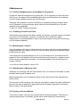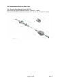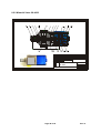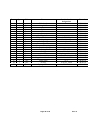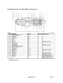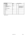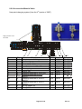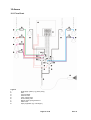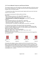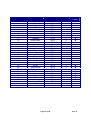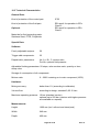
1
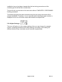
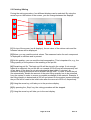
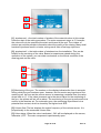
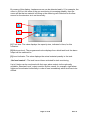
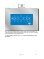
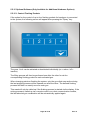
Service Manual
"Magic Flow"
Page 1 of 66
Feb. 13
Content
1 Identification Data
1.1
1.2
1.3
Preface
Identification of the Installation
Limited Warranty
Page 5
Page 5
Page 5
2 General
2.1
2.2
2.3
2.4
2.6
2.7
2.8
2.9
Notes for the User
General Safety Standards
Reaction Hazard
Fire and Explosion Hazard
Injection Hazard
Hazard by Escaping Liquids
Emergency Shutdown
Residual Pressure
Page 6
Page 6
Page 7
Page 7
Page 7
Page 7
Page 8
Page 8
3 Description of the System
3.1
3.2
3.3
Functional Characteristics
Mixing
Material Supply
Page 9
Page 9
Page 9
4 Installation
4.1
4.2
4.3
4.4
4.5
4.6
Transportation
Storage
Installation
Electrical Connections
Pneumatic Connections
Material Connections
Page 10
Page 10
Page 10
Page 11
Page 11
Page 11
5 Operation of the Installation
5.1
5.1.1
5.1.2
5.2
5.2.1
5.2.2
5.2.3
5.2.4
5.3
5.4
5.5
5.5.1
5.5.2
5.5.3
5.5.4
5.5.5
5.5.5.1
5.5.5.2
5.5.6
5.5.7
General
Turn on the Installation
Input of Numbers
Main Menu
Select Recipe
Start Spraying Procedure
Start Flushing Procedure
Adjust Settings
Painting / Mixing
Flushing
Settings
Recipes
Administration of Flushing
Valves
System Settings
Calibrate / Adjust K-Factors
Manual Adjustment of K-Factors
Determine K-Factors
Container Control
Printer Configuration
Page 2 of 66
Page 12
Page 12
Page 12
Page 13
Page 13
Page 13
Page 13
Page 14
Page 15
Page 18
Page 20
Page 21
Page 23
Page 25
Page 26
Page 28
Page 28
Page 28
Page 31
Page 32
Feb. 13
5.5.8
Reports
5.5.9
V.O.C. Values
5.5.10 Alarm Memory
5.5.11 Security Codes
5.5.12 Time
5.5.13 PLC Update
5.5.14 Display Update
5.5.15 Optional Software
5.5.15.1Control Flushing Pockets
Page 33
Page 34
Page 35
Page 36
Page 37
Page 38
Page 38
Page 39
Page 39
6 Maintenance
6.1
6.1.1
6.1.2
6.1.3
6.2
Cleaning and Maintenance of Material Component
Cleaning of Hoses and Tubes
Maintenance of Valves
Maintenance of Metering Cells
Cleaning of Control Module
7 Troubleshooting
and Alarm Messages
Page 41
8 Spare Parts and Options
8.1
8.2
8.2.1
8.2.2
8.2.3
8.2.4
8.2.5
8.2.6
8.2.7
Page 40
Page 40
Page 40
Page 40
Page 40
Spare Parts and General Options
Components with Spare Parts Lists
Material Valve 2K-2014
Material Valve 2K-4002
Material Valve CCV-403-SS-E (Low Pressure)
Volumeter
Air Flow Monitor
Accessories Material Valve
Touch Panel
9 Installation Shut-Off
Page 44
Page 44
Page 47
Page 47
Page 48
Page 50
Page 52
Page 54
Page 55
Page 59
Page 60
10 Annex
10.1
10.2
10.3
Flow Chart
Connect Material Component and
Electrical Cabinet
Technical Characteristics
Personal Notes
Page 61
Page 62
Page 64
Page 65
Page 3 of 66
Feb. 13
Finishing Brands Germany GmbH
Page 4 of 66
Feb. 13
1 Identification Data
1 Introduction
1.1 Preface
Dear Customer,
May we congratulate you for having purchased your new electronic Multi-Component
Installation.
Please be assured that design and fabrication of the installation have been carried
out according to state-of-the-art and with the intention of greatest possible user
comfort, highest safety level and selection of the best material.
May we point out that careful study and continued use of this manual will provide a
better understanding of the equipment and process, resulting in more efficient
operation, longer trouble-free service and faster, easier troubleshooting. Please
make sure that this installation must only be operated by adequately trained
personnel. For your safety also refer to the service manuals of peripheral equipment,
i.e. pumps, guns, and electrostatic equipment.
If you do have questions regarding the equipment, please contact our distributors or
us. We will be pleased to help you.
1.2 Identification of the Installation
If you do have any questions regarding the product please note the exact type
identification of the installation. You will find it on the type plate of the installation.
This will help to identify the installation regarding modification and equipment so that
we can offer qualified help to you.
1.3 Limited Warranty
All Finishing Brands equipment and spare parts are manufactured of the best
materials and with the most modern production procedure. Should you still have
reason for a claim send the defective part or the defective component directly to
Finishing Brands or to our distributor. Please understand that we cannot accept any
unfranked delivery. If your warranty claim is legitimate, we will refund transportation
costs to you.
We will check, replace, or repair defective parts that fall within the warranty. The
repair will be made in our house. If you wish the repair to be carried out at your site,
you will be charged for any eventually arising travel costs.
If, in our opinion the warranty item in question, or other items damaged by this part
was improperly installed, operated or maintained, we will assume no responsibility for
repair or replacement of the item or items.
Excluded from the warranty are normal wear parts, i.e. gaskets, packings and
nozzles.
Page 5 of 66
Feb. 13
Warranty period will be twelve months at one-shift operation, respectively six months
at two-shift- and three-shift operation, starting from date of initial operation, latest 30
days after delivery. Any other agreements must be drawn up in writing.
2 General
2.1 Notes for the User
The safety precautions and safety standards of this section have been compiled for
your safety and in your own interest. For safe operation it is necessary that the user
reads and understands all of the technical and safety literature. The user must be
familiar with the function of the installation und must be aware of the hazards and
risks that may occur with pressurized pumps, hoses, and equipment.
2.2 General Safety Standards
-
DO NOT move, operate, maintain or service the installation before reading
and understanding this service manual. If you do have any doubt or problem,
contact your superior or our representative.
-
NEVER leave tools or other mechanical components in the installation if it is in
operation or if it shall be started.
-
NEVER exceed the maximum pressure of the installation. The maximum
pressure of the installation is defined by the component with the lowest
maximum pressure. You will find the maximum pressure of the installation at
the type plate.
-
When replacing components ALWAYS exercise care that the new parts
comply with the technical data regarding material and maximum pressure.
-
ALWAYS ensure that the spray area is properly ventilated according to legal
requirements.
-
The equipment must ONLY be operated by authorized and adequately trained
personnel who have read and understood local codes, appropriate legal
requirements and this service manual. The personnel must wear personal
protection clothes and use appropriate tools during operation and
maintenance.
-
Before attempting any work AWAYS ensure the pressure is relieved from all
air and fluid hoses. Shut off pressure air supply to the installation and relieve
all pumps connected to the installation.
-
Before attempting any work at the electrical cabinet ALWAYS ensure the
board is current less. It is not sufficient that the main switch is in OFF position.
You must interrupt the complete current supply to the board.
-
When working with high-pressure spray equipment ensure that the guns are
NEVER operated without protection against accidental contact. ALWAYS
activate the safety-locking lever when not using the gun, in order to prevent
from unintended opening.
-
When finishing maintenance and repair works replace ALL protection covers
that have been removed from movable parts.
Page 6 of 66
Feb. 13
-
The use of other than genuine spare and accessory parts will void warranties.
-
After a longer period of shutdown check ALL components for leakage and
proper function.
2.3 Reaction Hazard
All fluid conducting parts of the installation are made of stainless steel in order to
avoid possible chemical reaction. However, in individual cases a chemical reaction
might occur if aggressive or chemically active materials are being used, which might
lead to dissolution or, in the worst case, to an explosion. If you want to use such
materials, contact the fluid manufacturer prior to operation in order to check the
compatibility of the fluid with different kinds of stainless steel.
2.4 Fire and Explosion Hazard
High flow rates of non-conductive materials may lead to an electrostatic charging.
This phenomenon frequently appears with airless systems because the flow rate is
very high and the material will be sheared and burst off at a small gap. In order to
avoid charging and spark discharge, all components must be electrically connected
with each other and grounded. Use suitable clamps and clean the contact parts of
spray mist, if necessary. Connect the clamps via suitable cable with sufficient mass
potential (permanently installed tubes etc.). If an electrostatic charging occurs, check
for proper grounding.
2.5 Toxic Solvents
Toxic and harmful vapors may be set free by the spray and mist of paints and other
materials. Follow all safety instructions of the manufacturer, keep to the relevant
lower toxic limit values and maintain adequate ventilation.
2.6 Injection Hazard
-
Never let any part of the body come in contact with the tip of the spray gun.
-
Never aim high-pressure spray guns at any part of the body or at other
persons under any circumstances.
-
The spray stream of high-pressure spray equipment can puncture the skin and
cause great harm. If such an incident occurs, in spite of all safety precautions,
seek medical care immediately and inform the doctor about the penetrated
material (see material data sheet).
2.7 Hazard by Escaping Liquids
Never modify the connections of the installation without prior contact with a
responsible person.
Regularly check the condition of hoses and connections. Take care that hoses are
not crushed and bent below the allowed radius.
Never overstrain hoses and connections by high mechanical load. Immediately
replace damaged hoses!
Page 7 of 66
Feb. 13
Check all connections prior to operation.
Never try to stop or deflect leaking material with your hands or other parts of the body.
2.8 Emergency Shutdown
In case of an accident or a hazardous situation turn the main switch in OFF position.
This will set all components of the panel current less and will close all valves.
2.9 Residual Pressure
Even after interruption of the air supply to the pumps, the lines fed by the pumps are
still not depressurized, as pressure can only be relived into one direction. In order to
depressurize the complete installation, open the spray gun und the relevant valves
via the control device (if no relief device is installed at the pumps).
Page 8 of 66
Feb. 13
3 Description of the System
3.1 Functional Characteristics
The system is designed to meter two or three volume flows, in which the main
volume flow (generally the main component) will be opened and all other
components (e.g. the hardener) will be regulated on basis of the metered first volume
flow according to the mixture ratio of the chosen recipe. All parameters and tolerance
values that are necessary for the calculations will be deposited in the system settings.
In order to guarantee highest possible safety, the function of the metering sensors
will be controlled on the one hand, and on the other hand the installation will be
shutdown if the demanded mixture ratio has not been achieved (e.g. insufficient
material).
On the basis of the high precision of the mixing and the controlled and economic
treatment with solvents and paint materials the electronic mixing and metering
installations are clearly superior to the mechanical metering installations.
3.2 Mixing
The installation is designed to regulate and inject the B component (optional also C)
into the running volume flow of side A. To obtain a good mixing result it is necessary
to connect a static mixer to the outlet of the installation (not included in scope of
delivery of basic installation). Care must be taken that the static mixer complies with
the maximum pressure of the complete installation. The length of the mixer, the
number of mix steps, and the diameter are depending on the used paint material, the
mixture ratio and the maximum volume flow. It may be necessary to insert a
downstream hose mixer (e.g. at very high flow rates).
3.3 Material Supply
Material supply will be made either by piston pumps, double diaphragm pumps, and
mono diaphragm pumps, or by pressure tanks. Care must be taken that all
components are operating in a similar pressure range. The combined operation with
pressure tanks and high ratio piston pumps is not recommendable.
It must be ensured that that the components of side B
(eventually also side C) have a higher pressure,
approximately 10%, than side A-, in order to be metered and
added on.
For proper operation of the installation at least the following equipment is necessary:
-
One fluid supply for side A
One hardener supply for side B
One flushing agent supply (according to paint system two off are possible)
If necessary, one thinner supply (for 3C installation)
Page 9 of 66
Feb. 13
4 Installation
4.1 Transportation
The installation consists – depending on the design – of one or two modules, which
can be transported separate from each other. The transportation will be done on
pallets. For the handling two persons are needed.
4.2 Storage
If the installation shall be stored, the control part must be protected against heat and
humidity. In order to avoid condensation of water the installation must not be
exposed to high temperature changes, otherwise the installation must be exposed to
the new ambient temperature with flaps open for several hours prior to operation.
The material component is extensively resistant against external influence, however,
for a longer period of storage it should be filled with preservative oil in order to take
care of the packings and to guarantee proper operation.
Operate the supply pumps according to the relevant service manuals of the pumps.
4.3 Installation
Generally the industrial installations of Finishing Brands will be installed by own
service technicians or service technicians of our representative. This is to avoid faults
at the very beginning caused by defective installation or operation.
If installation shall not be made by an Finishing Brands service technician, check the
completeness and the correct function of all components of the scope of delivery.
For installation always take care of the usability of the installation, the ambient
conditions (e.g. EEx explosion proof), and the safety of the operator.
WARNING: the control cabinet cannot be located in the EEx area. If operation in the
EEx area is necessary, a remote control panel is optionally available.
Page 10 of 66
Feb. 13
4.4 Electrical Connections
The installation will be supplied via a central electrical input at the control cabinet.
Pay attention to proper grounding of the necessary shock-proof plug. In the basic
version the fluid cabinet (material component) and the electrical cabinet will be
delivered separately. The connection of the two parts will be carried out according to
the description under Pos. 10.2 (Connect Material Component and Electrical
Cabinet).
4.5 Pneumatic Connections
The installation (in standard version) will be supplied via a central air connection. The
pressure must be at least 6 bar and must not exceed 8 bar! Please provide clean
industrial air and proper filtration and condensate separator. Use oil-free pressure air.
4.6 Material Connections
The material component must be supplied with at least – depending on the number
of components – one main color, one hardener and one flushing agent. The outlet of
the static mixer must be connected to the gun/the guns with a suitable fluid hose
(please refer to length and nominal pressure).
The hoses must be equipped with adequate hose connections according to the
installation. The threads must be in proper condition and must seal under pressurized
condition.
Page 11 of 66
Feb. 13
5 Operation of the Installation
5.1 General
5.1.1 Turn on the Installation
Turn on the installation by turning the main switch into position „ON“. Only turn the
installation on if the control cabinet is closed (high voltage). Opening of the control
cabinet at ON condition must only be done by qualified personnel and a service
technician.
Generally it is not necessary to turn off the installation. If the installation is in the main
menu and has been cleaned, the screen will independently turn off after an
adjustable period of time (see system settings, value „Standby“).
Do not turn off the installation in filled condition, control of the pot life will than no
longer be possible, resulting in the danger of material hardening in the installation.
5.1.2 Input of Numbers
To set the different parameters it is necessary to be able to enter numbers.
Generally this will be done by the input field shown below:
The value to be set is shown at the upper part on the left side. The value will be
deleted by pressing the „DEL“key (one decimal place each per key depression). The
value will be entered into the system by pressing the number fields and by pressing
the field „ENT“.
The name of the value (here „recipe“, i.e. recipe number), is described below the
value.
Page 12 of 66
Feb. 13
5.2 Main Menu
5.2.1 Select Recipe
By pressing the recipe number (here „1“) you are asked to enter a new recipe
number. Possible inputs are all recipe numbers from 1 to 50.
Below the recipe number, the name of the recipe will be displayed. On the icon
„Flushing“, the number of the stored flushing program (1-10) for this recipe will be
displayed.
If you have chosen a recipe number, which has been deposited in the recipe
administration as an inactive one, the display with the recipe parameters will flash.
You cannot start this recipe.
5.2.2 Start Spraying Procedure Press the spray icon – The icon activates the mixing procedure, provided that an
active recipe was chosen before.
5.2.3 Start Flushing Procedure Press the flushing icon - The icon will activate the flushing procedure. The flushing
procedure may be repeated as often as you wish (for example if several spray guns
are connected, which shall be cleaned one after the other). If the icon flashes, the
Page 13 of 66
Feb. 13
installation has not yet been cleaned after the last mixing procedure and the
remaining pot life will still be counted down.
The pot life will only be reset to the start value after a COMPLETELY PERFORMED
flushing procedure!
The flushing program that was activated during the last mixing procedure will be
selected by default. Therefore, it is not important which flushing program number is
displayed on the icon but which recipe was started and stopped last.
5.2.4 Adjust Settings This icon will lead you to the system settings. Here you can change for example
recipes, operating parameters and safety settings. According to the setting the
different sections may eventually only be entered via passwords.
Page 14 of 66
Feb. 13
5.3 Painting / Mixing
During the mixing procedure, four different displays can be selected. By using the
arrow keys on the bottom of the screen, you can change between the displays.
1
2
3
4
5
6
7
[1] On top of the screen (on all displays), the set value of the mixture ratio and the
selected valves will be displayed.
[2] Below, you can read the actual values. The measured value for each component
is displayed in milliliters and in percent.
[3] At this position, you can read the total consumption. This is important for, e.g., the
filling quantity of the system or the resetting of the pot life.
[4] Remaining pot life. The basic pot life will be stored in the recipe. If not enough
material is extracted, the pot life will run towards 00:00:00 and will subsequently set
off an alarm. If the alarm is not acknowledged in time (within 5 minutes), an
automatic flushing procedure will be started. IMPORTANT: In order to reset the pot
life automatically, double the amount of the paint filling quantity has to be extracted
from the system in order to ensure a complete exchange of the material. Example: If
the filling quantity is determined at 200 ml and stored on the system (system settings),
the pot life will be reset to the initial value after the removal of 400 ml, respectively.
[5] Using the arrow key, will take you to the previous display.
[6] By pressing the „Stop“key, the mixing procedure will be stopped.
[7] Using the arrow key will take you to the next display.
Page 15 of 66
Feb. 13
1
2
[1] „strokes now“= the total number of strokes of the material valves in this recipe
since the start of the mixing procedure. The main component stays at „0“because
the valve will only be opened at the start and closed at the end. The number of
strokes per volume provides information about the quality of the dosing. Many small
hardener injections result in a better mixing result than a few large injections.
[2] „strokes total“= the total number of strokes since the installation. This can be
helpful for the servicing of the valve. Based on experience gained during the
operation of the system, you can draw conclusions on the actual condition of the
wearing parts on the valve.
1
2
3
[1] Monitoring of the gun: The number on the display indicates the time in seconds
during which the gun has been open, however, did not receive any impulses of the
metering cell. As soon as the volume sensor is measuring a material flow, the value
drops back to „0“. If the value increases up to the stored value for the monitoring of
the gun, the system will set off an alarm. The monitoring of the gun is performed via a
sensor in the atomizer air. For automatic guns, the monitoring is performed via a
potential-free contact, which is closed by the higher-level SPS.
[2] Volume flow: The bar displays the output frequency of the volume sensor. It is
proportionally to the measured volume flow.
[3] Valve status: When the valve is activated, „ON“will be displayed on the screen,
otherwise „OFF“. The main component is permanently open.
Page 16 of 66
Feb. 13
By means of this display, hardware errors can be detected easily. If, for example, the
valve is „ON“but the value of the gun monitoring is increasing steadily, then the
cause will be that no material is flowing or the metering cell is blocked or the flow
sensor for the atomizer air is set incorrectly.
1
2
3
[1] Tank size: The value displays the capacity size, indicated in liters, for this
container.
[2] Minimum level: The programmed value displays from which tank level the alarm
output will be switched on.
[3] Level indicator: The value displays the actual material quantity in the tank.
„No level control“: The tank has not been activated for tank monitoring.
Up to 8 tanks can be monitored with their own alarm output via the optionally
available „Standard Level“output module. By this means, for example, eight alarm
lights can be activated individually in order to see immediately which tank has to be
refilled.
Page 17 of 66
Feb. 13
5.4 Flushing
3
4
5
6
1
2
7
8
9
10
[1] Actual flushing step: A flushing procedure may consist of up to 20 different steps.
All flushing steps, for which values are deposited, will be run in numerical order.
[2] To skip one flushing step: If the actual flushing step shall be skipped, press the
key and skip to the next flushing step, for which values are deposited.
[3] Valve number: The actually opened flushing valve is displayed.
[4] Flushing value: deposited set value of the flushing program, alternatively in „ml“or
in „sec“(see [5]).
[5] Dimension: Displays whether the actual flushing step will be done in milliliters or
in seconds. Fundamentally the cleaning of the installation in milliliters is process
safer. However, a quantity collection is not sensible for steps, which cause an air /
solvent flushing. Therefore, the dimension can be determined for each flushing step
separately (see flushing programming).
[6] Dump valve: It is possible to deposit for each step in the flushing program,
whether the signal „Dump Valve“shall be activated. This signal can then be used to
activate a gun cleaning box, or whether the cleaning shall be carried out via an
external dump valve.
[7] Begin loop: If a loop was programmed in the flushing program, which in
wraparound manner carries out certain steps for a certain number of repeat options,
then the first flushing step of this loop can be displayed here.
Page 18 of 66
Feb. 13
[8] Last step of the loop described under [7].
[9] Number of loop running (see [7]).
[10]
- This key will truncate the flushing procedure and will close all valves.
WARNING: If the flushing procedure will be truncated, the installation is still regarded
to be filled. The pot life is, therefore, still running!
For the refilling and flushing of several guns, an output module is available. You can
connect up to 4 dump valves or gun extractor units. If the system recognizes this
module during the switch-on, the operator will be prompted during the start-up of the
spraying process to enter the spray guns that should be activated. When the system
will be flushed at a later stage, the entered flushing procedure will run once for every
previously filled gun. During each run, another extractor unit will be activated in order
to ensure that every gun is flushed properly.
Page 19 of 66
Feb. 13
5.5 Settings
In the Tool Menu all installation parameters can be set. All settings can
influence the mixture result and should, therefore, only be carried out by
trained personnel or by service technicians! There is also the possibility to
protect all sub-menus by passwords and to inform only selected persons (see
„Codes“).
Page 20 of 66
Feb. 13
5.5.1 Recipes
Press the recipe key in order to enter the recipe administration (if necessary enter
security code):
Press the key for the recipe number, on top left, to select the recipe to be modified.
In the centre of the screen, you can choose any name for the recipe with up to 15
characters. This name will be displayed in the main menu under the recipe number.
This will make it easier for you to assign the recipes to the connected colors.
Use the chart, on top right: For the selected recipe a material valve can be allocated
to each metering channel (A / B / C), and the material portion for the recipe can be
determined. Please note that the volumetric mixture ratio will be entered. It is of no
importance whether, for example, for„A“4 portions and for „B“1 portion are entered,
or whether the mixture ratio will be entered as 100 : 25. During the mixing procedure
the main component will automatically be determined by the greatest portion of the
total mixture and permanently opened, while the other components will be metered
on.
Only enter values under „C“, if the installation is equipped as 3C installation.
Ensure that the entered valve numbers are really connected to the relevant metering
cells.
Adjust the pot life of the relevant mixture under t(min) (in minutes).
Page 21 of 66
Feb. 13
If an automatic pressure adjustment kit (optional) is connected to the installation, you
can determine the fluid pressure under p(bar), which will be adjusted after filling.
Under Flush, enter the flushing program that should be assigned to this recipe. You
can select one of the ten flushing programs that you set up earlier.
Under Active you can determine whether it is an active recipe that can be started
immediately. You can release recipes to the operator or close them off. Inactive
recipes will flash when they are selected in the main menu and cannot be used.
The icon with the crossed out disk rejects all modifications and loads down again all
50 recipes from the system memory.
The icon with the disk stores all modifications and will lead you back to the tool menu.
ATTENTION: During the cancelling or saving process, the control unit requires a few
seconds either in order to write the data of 50 recipes to the EEprom or to read them
on the EEprom. For this reason, do not try, UNDER ANY CIRCUMSTANCES, to
speed up this process by pressing especially hard on the display!
Page 22 of 66
Feb. 13
5.5.2 Administration of Flushing
Press the flushing program key in order to enter the administration of flushing (if
necessary enter security code):
First, you are asked to enter the number of the flushing program that you wish to edit.
You can enter the numbers 1 to 10.
3
4
5
6
2a
1
2b
7
8
9
10
[1] Actual flushing step which is being processed: A flushing procedure may consist
of up to 20 different steps. Only those flushing steps will run in numerical order where
values are deposited.
[2a] / [2b] Flushing step advance, flushing step return: changes to previous,
respectively next flushing step which shall be processed.
[3] Valve number: Number of the flushing valve which shall be opened in this step.
[4] Flushing value: set point value of this step which must run so that the installation
skips to the next step, alternatively in „ml“or in „sec“(see [5]).
[5] Dimension: Displays whether the actual flushing step will be done in milliliters or
in seconds. Fundamentally the cleaning of the installation in milliliters is process
safer. However, a quantity collection is not sensible for steps which cause an air /
solvent flushing. Therefore, the dimension can be determined for each flushing step
separately.
Page 23 of 66
Feb. 13
[6] Dump valve: It is possible to deposit for each step in the flushing program,
whether the signal „Dump Valve“shall be activated. The signal can then be used to
activate a gun cleaning box, or whether the cleaning shall be carried out via an
external dump valve.
[7] Begin: in the flushing program a loop can be programmed, which in wraparound
manner carries out certain steps for a certain number of repeat options. Here the first
step of this loop will be displayed.
[8] Last step of the loop described under [7].
[9] Number of loop running (see [7]).
[10]
- Key to store all modifications.
Page 24 of 66
Feb. 13
5.5.3 Valves
Press the valve key in order to enter the manual control panel for the connected
valves, signal outputs (optional), and pressure regulator (optional):
The keys 1 – 32 control the relevant valves. For security reason one fluid valve only
can be opened at the same time. If you want to close all valves again, press the key
„Valves OFF“.
The keys „S1“– „S8“control the special signals (output board with 8 power outputs in
24VDC optionally available):
S1: Mixing OK
S2: Ready
S3: Flushing
S4: Filling
S5: Dump Valve
S6: Filled
S7: Alarm
S8: HiFlow
Press the key “Signals OFF”to turn off all outputs.
You can test the optionally available pressure adjustment kit with the analogue
regulator. With „-„you will reduce the value by 0,1 bar, with „+“you will increase the
value by 0,1 bar. With „Analogue OFF“you will reset the value to 0,0 bar.
Page 25 of 66
Feb. 13
5.5.4 System Settings
In system settings important and security relating settings for the operation of the
installation can be entered. The correct setting of these parameters is of great
importance to the finish result and the trouble free operation of the installation.
Filling Quantity: On the one hand the filling quantity is important
for the external signal „Filling“to which, for example, a signal light can be connected
which indicates the operator that the filling procedure has not been finished. On the
other hand the filling quantity is needed to control the pot life. After removal of twice
as much filling quantity the pot life will be reset to start value. Removal of twice as
much filling quantity is necessary in order to prevent mixing of already reacting and
fresh material in the installation and in the hoses.
Incremental Size: The incremental size is necessary to control the
accurate mixing of the materials. The deposited value indicates the maximum interval
between two hardener metering injections in milliliters. Important: this value has no
influence on the quality of mixing! It only serves the control function. The installation
itself tries to meter the hardener in smallest possible injections. The cycle frequency
Page 26 of 66
Feb. 13
of the valve depends on overpressure of the hardener, needle stroke of the metering
valve, flow rate, viscosity and many others.
Generally the incremental size should be adjusted in such a way that mixing of the
material in the mixer can just be carried out. An incremental size of 100 ml for a static
mixer with filling volume of 20 ml may have the result that the material will not be
mixed accurately, but that the installation still operates without error signal.
Metering Cell Control: The indicated value indicates how long the
spray gun may be opened without the metering cell having to move. The control of
the gun opening in manual installations is generally carried out by the air flow control
integrated into the atomizing air. For automatic installations this signal can directly be
given by an external control.
When the painter opens the gun, the material flow should start shortly afterwards and
activate the gear wheels of the metering sensors. As long as a movement will be
recognized and impulses of the metering cells to the control of the mixing installation
are given, the control of the metering cells will be reset. If, however, a metering cell is
blocked because of contamination, so that it cannot recognize a volume flow, the
installation will give an alarm signal after the here deposited time.
The time should be in the range of 5-10 seconds in order to guarantee that no
unmixed material can escape the gun. However, the time should not be chosen too
short (less than 3 seconds) since the painter is using the gun sometimes to blow dust
from the object.
Display Brightness: Enter the value for the relative display
brightness in percent (0- 100%). Attention: If the value is too low you might not be
able to read the displays and will then not be able to increase the value!
Standby Time: The standby time in seconds indicates after which
time period the display turns off for longer service life of the lightning cathode. The
installation only switches to standby mode if it is flushed and if it is in the main menu
(all valves closed).
If the installation is in standby mode it is sufficient to touch the screen to return into
the main menu.
Page 27 of 66
Feb. 13
5.5.5 Calibrate / Adjust K- Factors
5.5.5.1 K- Manual Adjustment of K-Factors
For quick operation of the installation and for the general control of functions it is
generally sufficient, to enter into the system the construction wise given K-factors of
the volumeter. They are generally entered when the installation is supplied.
To take account of the different physical characteristics of the fluid to be metered, an
own K-factor can be entered for each valve and for each connected fluid. At the
same volumeter a highly viscose solvent based paint will cause another K-factor than
a cleaning thinner or a water based paint.
Press the single number fields (1 – 32) to read the deposited value. If you wish to
change this value (e.g. after retrofit to another volumeter), you can do this by
pressing the number input icon. (
).
5.5.5.2 K- Determine K-Factors
To increase the accuracy of the mixing installation it is recommendable to calibrate
all fluids. Follow the steps hereafter:
1. Press the icon with the mixing cup (
)
Page 28 of 66
Feb. 13
2. Select the volumeter that shall be calibrated:
3. Select the valve with which shall be calibrated:
Page 29 of 66
Feb. 13
4. Carry out the metering:
-
-
-
-
-
The bar on the left side indicates the flow rate. If the bar does not deflect
upwards when removing material, you have either selected a valve which is
not allocated to the selected volumeter, or the metering cell is mechanically
blocked.
The number on top right indicates the count of impulses. Open the spray gun
at first and remove material. The count-up counter must now display an
increasing value.
With the „START / RESET“- key you can reset the count-up counter to Zero.
Press the key after having filled the system with material, wait for some
seconds and start the actual metering.
Remove a well readable quantity of material into a metering cup. Close the
spray gun and wait for some seconds until the count-up counter has come to
standstill.
Finally press the „OK“- key. You will then be asked to enter the volume of the
removed material.
The resulting K-factor will be displayed and will then be entered into the
system.
Page 30 of 66
Feb. 13
5.5.6 Container Control
The integrated container control serves the control of the container level without
additional sensory mechanism. If a container shall be controlled it is necessary to
deposit into the menu its level prior to use.
Starting from the metered consumed material quantity the system can give an alarm
signal if a defined minimum level is reached, in order to avoid no-load operation of
the pumps with the result of defective mixtures and failures.
With the buttons [1] – [32] the container will be selected which shall be adjusted or
controlled.
With the button [MAX LEVEL] the size of the container will be determined, which it
had when delivered.
[ACTUAL CONTENT] displays the actual container level. Press the button to refill the
container numerically or to enter any new level.
[MIN LEVEL] displays the minimum level. An alarm signal will be given if the level
falls under this value. Press the button to adjust the level.
[ACTIVE] resp. [NOT ACTIVE] will display whether the control shall be activated. If
the button is in [ACTIVE] mode, an alarm signal will be given. If the button is in [NOT
ACTIVE] mode, the container level will be calculated, but the minimum level will be
ignored.
Page 31 of 66
Feb. 13
5.5.7 Printer Configuration
[UNIT ID] displays the name of the mixing installation which appears on the prints. It
is therefore possible to distinguish between the prints of different installations. The
name can have up to 10 characters.
[PRINTING AFTER … ml] displays in which intervals process information shall be
printed. In the above shown case a print would be started after every removal of one
liter material.
[PRINTING AFTER … sec] displays the intervals during the mixing procedure when
prints shall be printed.
It is possible to activate the two print variants, but also only one or none of them. If
you do not wish to have prints made, set the values to „0“.
Set the following parameters on the printer interface that is provided as standard
(serial):
Baud: 9600 (8 bit / no parity / 1 stop bit), no hardware handshake
Page 32 of 66
Feb. 13
5.5.8 Reports
Use the keys [1] to [32] to select the valve, respectively the component where you
wish to read the consumption.
[TOTAL] displays the total consumption of the component since installation of the
system. It is not possible to reset this value.
[JOB] displays the consumption since the last reset of this value. It is, therefore,
possible to collect the weekly consumption, for example. The operator can reset this
value with the key [RESET JOB].
As well as at the count of total consumption, as at the job count the consumption of
the component is listed and its VOC content. The relative VOC content in percent
can be set in the VOC Menu (see 5.5.9).
Press the key [PRINT ALL] in order to print the consumption value of all components,
as far as the optionally available printer is connected.
Page 33 of 66
Feb. 13
5.5.9 V.O.C. Values
Press the keys [1] to [32] to select the valve, respectively the component where you
wish to adjust the VOC value.
The VOC value (in %) will be displayed in the mid. Press the key [V.O.C.] to adjust
the value for each valve separately. The value is needed in order to calculate for the
consumption reports not only the consumption but also the VOC emission.
Page 34 of 66
Feb. 13
5.5.10 Alarm Memory
The mixing installation stores up to 100 alarm messages in sequence of appearance.
You can scroll through the alarm history with the keys [ß] and [à]. If more than 100
errors were collected, the last 100 messages are still available.
Each alarm message is listed with date and time as well as with the reason for the
alarm.
The significance of the alarm icons you will find in the Chapter „Alarm Messages“.
Page 35 of 66
Feb. 13
5.5.11 Security Codes
When delivered all menus are accessible without code input. (Input „0“). After
installation and initial operation all security relating settings should be secured
against unauthorized access.
The setting of the passwords will be done in the same manner as an eventually later
necessary adjustment of the codes.
To set a code you press the above shown key icon. You will be asked to enter the
“master code”which for reasons of security is not part of this documentation. It will be
sent separately to you from Finishing Brands / Binks. After input of the code you
press the field the menu of which you want to secure with a new password. You will
see the input picture „new code“. Enter here your new secret number. The code will
automatically be stored.
If you should forget or mislay your access code you can also use this procedure in
order to find out the deposited code. But carefully keep the master code because it is
an unchangeable part of the software of the control.
Page 36 of 66
Feb. 13
5.5.12 Time
Press the key [SET CLOCK] in order to set the internal clock of the installation. The
clock has a movement reserve of approximately 10-14 days. The clock is necessary
to print reports and for storing alarm messages.
To change values you press the keys [+] / [-]. To store the modifications you press
the key [OK].
Page 37 of 66
Feb. 13
5.5.13 PLC Update (Software- Update)
The PLC should receive new updates in exceptional cases only, and only by
authorized and qualified personnel. However, should you press this key, the
installation switches into the so called „HOST Mode“, in which it is ready to receive
new software. You can only return from this mode to the normal operating mode by
turning off the power supply or by pressing the “Reset”key on the PLC main board.
5.5.14 Display Update (Software- Update)
The display, too, should receive new updates in exceptional cases only, and only by
authorized and qualified personnel. However, should you press this key, PLC
switches into the receive mode for new display software which in turn will be
transferred to the display by PLC. The display signals „Waiting for data“.
You can only return from this mode to the normal operating mode by turning off the
power supply or by pressing the “Reset”key on the PLC main board.
Page 38 of 66
Feb. 13
5.5.15 Optional Software (Only Available for Additional Hardware Options)
5.5.15.1 Control Flushing Pockets
If the option for the control of up to four flushing pockets for handguns is connected
to the system, the following screen will appear after pressing the “Spray”key:
The guns 1 to 4 can be activated or deactivated individually (on = active / off =
inactive).
The filling process will then be performed one after the other for via the
corresponding flushing pocket for each activated gun.
When changing paints or flushing the system, only the guns that were active during
the last spraying process will be cleaned one after the other. The defined flushing
process will then run exactly once for each gun.
This mask will only be called up if the flushing process is started via the display. If the
mixing process is called up via a remote control or a robot communication module,
the last selected gun combination will be automatically applied again.
Page 39 of 66
Feb. 13
6 Maintenance
6.1 Cleaning and Maintenance of the Material Component
Protect the material component from spray mist. If it is necessary to clean the area
with thinner, the power of the installation must be turned off because the metering
sensors of the standard version are not EEx-proof.
Generally the installation must be cleaned by a complete flushing procedure after
end of operation or during a longer spray interval to avoid hardening of the paint
material in the installation.
à See 5.2.3 Start Flushing Procedure
6.1.1 Cleaning of Hoses and Tubes
If the flushing procedures have been carried out properly, a special cleaning of hoses
and tubes is not necessary. However, if reactions occur inside the system,
replacement is recommendable in order to avoid solid parts coming off and entering
into the system gradually.
6.1.2 Maintenance of Valves
If a color change valve has not been used for a longer period it is recommendable to
disassemble the color supply unit and to flush the valve, otherwise solid parts might
settle inside the valve.
If the valves do not operate properly or if air or fluid leaks occur, the seals must be
replaced. Since the hardener valves are activated more frequently, a regular control
of the valves is absolutely necessary. It is recommendable to service the valves in
regular intervals.
You will find further details in Annex 10.5.
6.1.3 Maintenance of Metering Cells
Generally our metering cells are maintenance-free. If it should be necessary to clean
blocked metering cells, please note:
Metering cells have to be treated according to the instructions of the manufacturer,
Annex (10.4).
The accuracy of the metering cells must be controlled in regular intervals (calibration),
because the use of abrasive or pigmented fluids will lead to wear which influences
the accuracy of the gear wheels.
6.2 Cleaning of Control Module
The control module must only be cleaned with a soft cleaning agent. There are no
internal components or assembly groups which need cleaning or maintenance.
Page 40 of 66
Feb. 13
Cleaning of the touch-screen-display with solvents is not allowed. If you expect high
grade contamination of the display there are slightly self-sticking transparent
protection foils available which can easily be exchanged.
7 Alarm Messages and Troubleshooting
General Problem
Alarm Message:
Possible Cause
Atomizing air is open
without spraying
Solution
Set longer activating time
for metering cell control
Do not open atomizing air
unnecessarily
(no volume flow, A side)
Tip clogged (no material
flow with gun open)
Color change valve
connected to wrong
solenoid valve (no trigger
air signal)
Color change valve does
not open although trigger
air is applied
Lack of material
Defective feed pump
Blocked metering cell
Defective sensor on
metering cell
Cable rupture or wrongly
connected
Page 41 of 66
Clean tip, replace if
necessary
Check allocation of color
change valves to solenoid
valves
Disassemble color
change valve, clean,
replace seals (see service
manual for valve)
Check material supply
system on A side (empty
container?)
Check functioning of
pump (see service
manual of pump)
Start flushing procedure,
disassemble metering cell
and clean if necessary
Contact service
technician, replace
metering cell
Meter cable, replace if
necessary
Feb. 13
General Problem
Alarm Message:
Possible Cause
Atomizing air is open
without spraying
Solution
Set longer activating time
for metering cell control
Do not open atomizing air
unnecessarily
(no volume flow, B or C
side)
Hardener pressure too
low
Tip clogged (no material
flow with gun open)
Color change valve
connected to wrong
solenoid valve (no trigger
air signal)
Color change valve does
not open although trigger
air is applied
Lack of material
Defective feed pump
Blocked metering cell
Defective sensor on
metering cell
Cable rupture or wrongly
connected
Page 42 of 66
Set hardener pressure to
pressure of main color +
approximately 10%
Clean tip, replace if
necessary
Check allocation of color
change valves to solenoid
valves
Disassemble color
change valve, clean,
replace seals (see service
manual for valve)
Check material supply
system on B side (empty
container?) (alternatively
C side)
Check functioning of
pump (see service
manual of pump)
Start flushing procedure,
disassemble metering cell
and clean if necessary
Contact service
technician, replace
metering cell
Meter cable, replace if
necessary
Feb. 13
General Problem
Alarm Message
Possible Cause
Difference of pressure too
high (injections too large)
à Recognizable by heavy
pulsations at the gun
Solution
Slowly reduce hardener
pressure, reduce needle
stroke at metering valve
(Mixing tolerance A/B/C
exceeded)
Uneven operation of feed Check pumps, clean and
pumps
replace packings if
necessary
Incremental size selected Adapt incremental size
too small
within the possibilities
Flow rate too high (for
Adapt incremental size
example by filling without within the possibilities.
spray tip)
Only fill with tip
General Problem
Alarm Message
Possible Cause
Installation has not been
flushed in good time
Solution
Start flushing procedure
Not sufficient material
removed from installation
within pot life period
Start flushing procedure
(Potlife expired)
Page 43 of 66
Feb. 13
8 Spare Parts and Options
8.1 Spare Parts and General Options
Item No.:
Description
Merchandise Group Basic Installations Magic Flow
2K-2000
2K-2001
2K-2002
Magic Flow, electronic 2-component mixing und metering installation;
electronic control cabinet, 600 x 380 x 210 mm with touch-screen,
pneumatic / hydraulic control cabinet, 600 x 700 x 210 mm, equipped for
1 main color, 1 hardener, 2 flushing agents, metering range:
50-2000 ml/min per component. Compression-proof up to 250 bar, incl.
1 static mixer 300 mm length, 10x8 mm, Finishing Brands Order. No.:
2K-2000
Stand post, aluminum profile construction for 2-C installation,
hight:1500 mm, depth: 400 mm; control cabinets can be mounted with
height adjustment
Wheels set, 2 off guide rolls, 75 mm, antistatic, with double block-up
brake, completely mounted
Merchandise Group Electronic Magic Flow
2K-2004
2K-2049
Expansion card for 8 solenoid valves, slot card for control "Magic Flow";
card will be pushed into the main board and delivers 8 digital 24V
outputs to trigger solenoid valves. Cards are addressable for the valves
1-8, 9-16, 17-24 or 25-32; maximum of 6 expansion cards can be
integrated into the control.
Signal output card, output card with 8 off 24V outputs to trigger external
signals, e.g. "Alarm", "Flushing", "Fill" etc.; callipered power: max.
approx. 400mA per channel, max. 2000mA total. Can be used to trigger
directly signal lights, horns, etc.
Switching power supply 230VAC / 24VDC3.2A, 75W top hat mounted
2K-2073
Line safety switch, Characteristics: B16
2K-2050
Main board, supplied without output cards, supplied without display
2K-2051
Processor for main board, Chip set Siemens Infineon CI144 preprogrammed
2K-2052
Touch screen, LCD display with analogue touch field, 240 x 128 Pixel,
CFL lightning, blue / white; pre-programmed for "Magic Flow"
2K-2074
Optoelectronic coupler input card; Optoelectronic coupler input 24VDC
signal; connection for power supply, signal transmitter
2K-2064
Air flow control, adjustable, air connections: 3/8" (F)24V power supply,
signal output 24V (PNP switching)
2K-2005
Page 44 of 66
Feb. 13
Merchandise Group Spare Parts Magic Flow
2K-2011
Solenoid valve plate 3/2 controls "Magic Flow", 2 x 3/2 controls, 4mm
2K-2012
Solenoid valve plate 5/2 controls "Magic Flow", 1 x 5/2 controls, 4mm
2K-2071
Integrated gauge "Magic Flow", 010 bar, 40 mm, front montage
2K-2070
Air regulator "Magic Flow, "3/8" air regulator, range of adjustment
0-10 bar
Merchandise Group Fluid Part Magic Flow
2K-2015
2K-2016
Volumeter "Magic Flow"
Volumeter, Stainless Steel 1/4" (F), P(max) 250 bar, metering range
50-2000ml/min, slide bearing
Single Pickup "Magic Flow"
Pickup for volumeter, not EEx-proof, connection M12, four conductor
2K-2017
Single Pickup "Magic Flow", EEx
Pickup for volumeter, EEx proof, connection M12, four conductor
2K-2018
Section switch amplifier
Section switch amplifier for volumeter, 1-channel design for top hat
2K-2019
Pair of gear wheels "Magic Flow"
Pair of gear wheels incl. slide bearing bush, ca. 8.800 impulse / liter
2K-2020
Shaft volumeter "Magic Flow"
2K-2021
Connecting cable volumeter "Magic Flow"
Connecting cable, 5m, yellow (not EEx)
2K-2022
Extension cable volumeter per meter
alternatively yellow or blue
Merchandise Group Options Magic Flow
2K-2006
EEx-proof kit "Magic Flow"
Conversion kit for "Magic Flow", includes: 2 off EEx sensors for
volumeter (in exchange for standard sensors), 1 off EEx solenoid valve
(5m cable), 2 off section switch amplifiers
Page 45 of 66
Feb. 13
2K-2007
Robot communication kit
8 off optoelectronic coupler inputs
8 of optoelectronic coupler outputs
In top hat housing, for connection to PLC bus, cable length max.:
approx. 1m
2K-2008
Transceiver kit
2 off transceiver units for PLC bus "Magic Flow"
- without cable
- for the connection of external PLC modules for a distance of more than
one meter
Recommended cable to connect the units: CAT5 / CAT6 network cable,
twisted pair, shielded
Non-ex remote control with recipe display (additionally, a transceiver kit
2K-2008 is required)
Ex remote control (category 2) with recipe display (additionally, a
transceiver kit 2K-2008 is required)
Pneumatic remote panel for Magic Flow
3 functions: Start / Stop / Flushing
3 off P/E converter and 3 off pneumatic buttons
Isolated design (2 off metering cells) Magic Flow
Dual pick-up for metering cell with fiber optic output, fiber optic cable
(5m), fiber optic receiver and Lithium battery. EEx-proof. Two sets each,
including an external solenoid valve, which will be installed as close as
possible to the fluid part, but outside the high voltage area.
2K-2026
2K-2047
2K-2010
2K-2072
Page 46 of 66
Feb. 13
8.2 Components with Spare Parts Lists
8.2.1 Service Kits Material Valve 2K-2014
Service Kit 2K-2044 includes the items 6, 9 and 14 (1 each)
Service Kit 2K-2059 includes the items 2, 3, 7, 10, 11, 14, 15 and 20 (1 each)
Page 47 of 66
Feb. 13
8.2.2 Material Valve 2K-4002
Material valve
2K-4002
Page 48 of 66
Feb. 13
Pos.
Qty.
Unit
Name
1
2
3
4
5
6
7
8
9
10
11
12
13
14
15
16/17
18
21
27
28
29
1
1
1
1
1
2
1
4
1
2
1
1
1
1
1
1
1
1
1
1
4
pcs.
pcs.
pcs.
pcs.
pcs.
pcs.
pcs.
pcs.
pcs.
pcs.
pcs.
pcs.
pcs.
pcs.
pcs.
pcs.
pcs.
pcs.
pcs.
pcs.
pcs.
Valve body
Air cylinder
Cap
Piston
Nut
Spacer
Packing holder
Fillister head screw
Sealing ring
Sealing ring
Fastening screw
Compression spring
Compression spring
O-ring
O-ring
Seal kit
Valve needle
Locking piece with valve seat
Screw plug
O-ring
Spring washer
Page 49 of 66
Standard code
designation
M4 x 40 DIN 912-8.8 vz
12 x 16 x 1.5
14 x 18 x 1.5
G¼
25.3 x 2.4
3.3 x 2.4
3 x diaphragm / 3 x O-ring
11/16" x 1 6 UN
G¼
Ø 10 x 2 Viton
4A, DIN 7980 vz
Feb. 13
Remarks
2K-4100
2K-4101
2K-4102
2K-4103
2K-4104
2K-4105
2K-4106
2K-4107
2K-4108
2K-4109
2K-4110
2K-4111
2K-4112
2K-4113
2K-4114
2K-4115
2K-4116
2K-4117
2K-4118
2K-4119
2K-4120
8.2.3 Material Valve CCV-403-SS-E (Low Pressure)
Page 50 of 66
Feb. 13
Page 51 of 66
Feb. 13
8.2.4 Volumeter 2K-2015
Page 52 of 66
Feb. 13
Spare Parts for Volumeter 2K-2015
For the volumeter the following spare parts and wear parts are available
Pair of gear wheels
Shaft gear wheel
Disc washer (material PTFE)
Disc washer (material Viton, FEP sheathed)
2K-2019
2K-2020
2K-2057 or
2K-2058
Other volumeters are available on request (higher or lower resolutions, various
bearings).
Page 53 of 66
Feb. 13
8.2.5 Airflow Control for Atomizing Air LG 518 GSP – Part No. 2K-2053
Page 54 of 66
Feb. 13
8.2.6 Accessories Material Valve
New paint changing system (from the 4th quarter of 2007)
High-pressure valve
Hochdruckventil CCV300
2K-2004
No.
Qty. Name and finished dimensions
1
2
3
4
5
6
7
8
9
1
1
1
10
4
11
4
12
13
4
4
4
End plate push-fit fitting
Spacer
End plate G 1/4i
O-ring Ø 10 x 2 Viton
Hex. socket screw M4 x 40
Dummy plug
Plug G 1/4i
Clamping screw M5 x 16 IP1+31
Clamping screw M5 x 60 IP1,
1x2+31
Clamping screw M5 x 100 IP1,
2x2+31
Clamping screw M5 x 140 IP1,
3x2+31
Spring washer A5
O-ring Ø 10 x 2 Viton
Page 55 of 66
DIN Material Remarks
14305
14305
14305
931
8.8-vz
14305
Farbwechselsystem
14305
CCV300
912 8.8-vz
912 8.8-vz
2K-4121
2K-4122
2K-4123
2K-4124
2K-4125
2K-4126
2K-4127
2K-4128
2K-4129
912
8.8-vz
2K-4130
912
8.8-vz
2K-4131
7980
2K-4132
2K-4133
Feb. 13
2K-2027
Return valve ¼”BSP
à M16x1,5
2K-2029
Color change stack, 2 + 2
(until 2007)
2K-2030
2K-2031
Color change stack, 4 + 2
Color change stack. 6 + 2
(until 2007)
2K-2032
Fitting ¼”BSP à M16x1,5
Page 56 of 66
Feb. 13
2K-2033
Screw plug ¼”BSP, short
version for color change
stack
2K-2034
Disc washer Stainless Steel
for color change stack
(until 2007)
2K-2035
Adapter for high pressure
valve on color change stack
(until 2007)
2K-2036
Seal ¼”, aluminum
Page 57 of 66
Feb. 13
51410L14
Adapter, adjustable, ¼”
BSP to M16x1,5
2K-2160
Adjustable T-screw
connection, M16x1,5
2K-2038
Adjustable L-screw
connection, M16x1,5
Page 58 of 66
Feb. 13
8.2.7 Touch Panel
TOUCH PANEL ADJUSTMENT
The touch panel is adjusted on delivery and can be used immediately. Due to aging
and wear, it may be necessary to readjust the touch panel.
Adjustment procedure:
1. When switching on, touch the panel until the following message appears:
"touch adjustment ?"
Now, you can stop touching the panel.
2. Within one second, touch the panel again for at least one second.
3. Follow the instructions for the adjustment (touch the two points on the top left and
bottom right corner of the panel).
The touch panel is available under article number 2K-2052. Alternatively, e.g. in case
of a glass breakage, a replacement display can be obtained under the article number
2K-2052-REP.
Page 59 of 66
Feb. 13
9 Installation Shut-ff
If the installation shall be shut-off for a longer period of time the following steps must
be carried out:
1. Carry out at least one complete flushing procedure in order to remove mixed
material from the installation.
2. Depressurize all fluid supply systems.
3. Open manually all connected valves via the relevant menu, in order to relieve
residual pressure.
4. Remove all supply hoses from the color change valves.
5. Connect the flushing agent supply system to each valve in succession, open
the valve manually and flush it via the gun or via a hose connected to the
outlet.
6. Remove the flushing agent supply system.
7. Fill into each valve some milliliters preservative agent and close it with a screw
plug.
8. Remove the electrical and pneumatic supply connections.
9. Store the installation at a dry location.
Page 60 of 66
Feb. 13
10 Annex
10.1 Flow Chart
Legend:
1
2
3
4
5
6
7
8
9
Fluid supply system (e.g. piston pump)
Filter
Control cabinet
Solenoid valve
Color change valve
Flow metering cells
Return valves, spring tensioned
Static mixer
Spray applicator (e.g. manual gun)
Page 61 of 66
Feb. 13
10.2 Connect Material Component and Electrical Cabinet
The material cabinet and control cabinet are delivered separately in the basic version.
After mechanic assembly air- and cable connections must be made between the two
separate units. Proceed as follows:
1. Connect the air outlet of the electrical control cabinet with the air inlet of the fluid
cabinet (10 mm air hose).
2. Connect the metering cell cables (yellow) as follows:
Main color:
- black and brown lead onto +24V of the CNTO- insert card
- blue and silver lead (sheath) onto GND of the CNTO- insert card
- white lead onto CNT + of the CNTO- insert card
- connect also CNT- with GND via a cable jumper on the CNTO- insert card
Hardener:
- black and brown lead onto +24V of the CNT1- insert card
- blue and silver lead (sheath) onto GND of the CNT1- insert card
- white lead onto CNT+ of the CNT1- insert card
- connect also CNT- with GND via a cable jumper on the CNT1- insert card
3. Connect the control cable of the solenoid valve island as follows:
The solenoid valve island has a 25 channel cable (orange). The green/back lead
builds the +24VDC reference connection, all other cables will be connected to the
digital output cards of "Magic Flow".
The output cards have 10 connecting terminals:
GND ; 24V ; DO.O ; DO.1 ; DO.2 ; DO.3 DOA ; DO.5 ; DO.6 ; DO.7
Attention: GND will not be wired!
Via an address jumper it can be defined which solenoid valves will be triggered by
the respective card.
Valves 1-8
32
(Card 1)
Valves 9-16
Valves 17-24
(Card 2)
(Card 3)
Valves 25Card 4)
A solenoid valve island can have a maximum of 24 off 3/2 control valves. If more
than 24 valves shall be triggered, another solenoid valve island is necessary. In the
following chart the first solenoid valve island is called „A“and the second solenoid
valve island „B“. If using a second solenoid valve island the green/black lead must be
connected to „24 V“of card 4. Green/black of the first solenoid valve island must be
connected to „24 V“of card 1.
Page 62 of 66
Feb. 13
Valve
Lead
Connection
Card
1
2
3
blue/black
red/brown
white/black
red/blue
black/orange
yellow/red
black/brown
white/red
red/black
brown/white
red/orange
light blue
yellow/white
yellow
red/green
orange
orange/white
green
yellow/black
white
white/blue
brown
green/white
red
blue/black
red/brown
white/black
red/blue
black/orange
yellow/red
black/brown
white/red
DO.0
DO.1
DO.2
DO.3
DO.4
DO.5
DO.6
DO.7
DO.0
DO.1
DO.2
DO.3
DO.4
DO.5
DO.6
DO.7
DO.0
DO.1
DO.2
DO.3
DO.4
DO.5
DO.6
DO.7
DO.0
DO.1
DO.2
DO.3
DO.4
DO.5
DO.6
DO.7
1
1
1
1
1
1
1
1
2
2
2
2
2
2
2
2
3
3
3
3
3
3
3
3
4
4
4
4
4
4
4
4
4
5
6
7
8
9
10
11
12
13
14
15
16
17
18
19
20
21
22
23
24
25
26
27
28
29
30
31
32
Page 63 of 66
Valve
Island
A
A
A
A
A
A
A
A
A
A
A
A
A
A
A
A
A
A
A
A
A
A
A
A
B
B
B
B
B
B
B
B
Feb. 13
10.3 Technical Characteristics
General Data:
Kind of protection of the control part:
IP 52
Kind of protection of the fluid part:
EEx-proof for operation in EExClass 2
EEx-proof for operation in EExClass 1
Optional:
Materials for fluid contacting parts:
Stainless Steel, PTFE, Polyamide
Special Data:
Software:
Freely adjustable recipes:
50
Trigger able components:
32
Deposit able parameters:
No. A + B + C, mixture ratio,
Pot life, optional fluid pressure
Adjustable flushing parameters: 20 steps, valve number each, quantity or time,
dump valve
Storage of consumption of all components
Mixture ratio:
0 – 200% metering on to main component (100%)
Hardware:
Mixing accuracy:
better than 1% (according to calibration)
Volume flow:
according to design, standard 0,05- 2 l/min
Maximum operating pressure: 10 bar (standard version)
optional up to 250 bar (versions with higher pressure
are available on request)
Measurements:
Height:
1600 mm (incl. rolls set and stand post)
Width:
640 mm
Depth:
400 mm
Page 64 of 66
Feb. 13
Personal Notes:
Page 65 of 66
Feb. 13
Finishing Brands (UK) Limited
Finishing Brands Germany GmbH
Ringwood Road, Bournemouth,
BH11 9LH England
Tel: +44(0) 12 02 57 1 1 11
Fax: +44(0)12 02 57 34 88
E-mail: [email protected]
Justus-von-Liebig-Str. 31,
D-63128 Dietzenbach
Tel: +49 (0) 60 74/403-1
Fax: +49 (0) 60 74/403-300
E-mail: [email protected]
Surfaces et Finitions
163-171 Av. des Auréats,
26014 Valence cedex FRANCE
Tel: +33 4 75 75 27 00
Fax: +33 4 75 75 27 59
E-mail: [email protected]
www.finishingbrands.eu
Page 66 of 66
Feb. 13