1
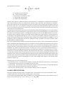
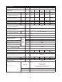
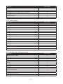
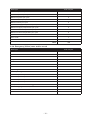
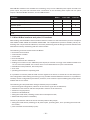
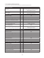
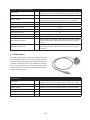
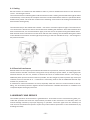
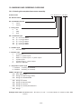
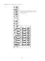
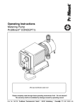
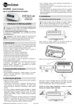
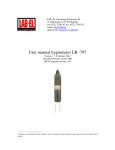
Apator SA, ul. Gdańska 4a lok. C4, 87-100 Toruń, POLAND
e-mail: [email protected], www.apator.com
Sales:
Apator Powogaz SA, ul. K. Janickiego 23/25, 60-542 Poznań, POLAND
e-mail: [email protected]
tel. +48 61 8418 133, 136, 138, 148
Compact Heat Meter
ELF
Technical description
For firmware versions 1.01+
ISO 9001
PN-N-18001
ISO 14001
Contents
1. SUBJECT...................................................................................................................................................3
2. REGULATORY AND STANDARD COMPLIANCE.....................................................................................3
3. DESIGN, FUNCTIONAL DESCRIPTION & BASIC CHARACTERISTICS....................................................3
4. BASIC SPECIFICATIONS..........................................................................................................................4
5. DATA TYPES.............................................................................................................................................7
5.1. Actual data.............................................................................................................................................7
5.1.1. Heat consumption..............................................................................................................................7
5.1.2. Water volume.....................................................................................................................................7
5.1.3. Supply and return temperatures; differential temperature..............................................................7
5.1.4. Power and flow...................................................................................................................................8
5.1.5. Pulse inputs........................................................................................................................................8
5.1.6. Error codes.........................................................................................................................................8
5.1.7. Real time.............................................................................................................................................9
5.2. Calibration, configuration and service data.........................................................................................9
5.2.1. Metrology-specific calibration and configuration data.....................................................................9
5.2.2. User configuration data......................................................................................................................9
5.3. Archive data.........................................................................................................................................10
5.3.2. Cycle 2 record...................................................................................................................................11
5.3.3. Monthly and annual cycle record....................................................................................................11
5.3.4. Emergency (failure) state archive record........................................................................................12
6. HEAT METER OPERATING GUIDE. LCD................................................................................................13
6.1. Metrological test..................................................................................................................................14
7. REMOTE READING OF DATA.................................................................................................................15
7.1. Wired M-Bus interfaces and pulse I/O interfaces...............................................................................16
7.1.2. Interface technical parameters........................................................................................................18
7.1.3. Operating principle of the M-Bus communication interface..........................................................19
7.1.4. Pulse output configuration...............................................................................................................19
7.2. Wireless interface................................................................................................................................19
7.3. USB interface.......................................................................................................................................20
8. SHIPPING AND MOUNTING..................................................................................................................21
8.1. Sealing.................................................................................................................................................22
8.2. Electrical interference..........................................................................................................................22
9. WARRANTY AND SERVICE...................................................................................................................22
9.1. Recommendations for end of life.......................................................................................................23
10. MARKING AND ORDERING GUIDELINE..............................................................................................24
10.1. Ordering the complete heat meter assembly..................................................................................24
10.2. Ordering the communication modules ...........................................................................................25
11. ANNEXES.............................................................................................................................................26
1. SUBJECT
This description is intended to present the characteristics, parameters and operation of Elf compact heat
meters manufactured by Apator-Powogaz. The heat meters are intended to meter the heat consumption
taken from heat distribution networks by small loads (e.g. apartments) with the heat power rating of 0.3
kW to 850 kW with Building Code compliant treated water as the heating medium. The heat meters are
manufactured in five sizes for four nominal volume flow sizes. The sizes differ in diameter and connection
types. The heat meter consists of a flow transducer, a pair of Pt 500 temperature sensors with wells and
an electronic indicator resolver. All components form an integrated set for the user, i.e. the complete
heat meter. The installed sensors are type TOPE42 Pt 500 temperature sensors and butterfly flowmeters
without magnetic coupling which must be operated with only one specific type of electronic resolver.
Elf heat meters are compatible with remote reading interfaces and with up to four additional devices (e.g.
a water meter or a gas meter) equipped with pulsers. The interfaces available are: one Wireless M-Bus,
one M-Bus interface which enables connecting 2 additional pulsers and features a pulse output, an M-Bus
for connecting 4 additional pulsers, and one M-Bus with 4 additional pulser inputs or 3 pulser inputs and
one pulse output.
2. REGULATORY AND STANDARD COMPLIANCE
• Directive 2004/22/EC of the European Parliament and of the Council dated 31 March 2004 on measuring instruments, with specific consideration to Annex MI-004, Heat Meters.
• PN-EN-1434 – Heat meters, 6 parts.
• PN-EN 61000 – Electromagnetic compatibility (EMC). Parts 2-4.
• PN-EN 13757 – Communication systems for meters and remote reading of meters. Parts 1-4
3. DESIGN, FUNCTIONAL DESCRIPTION & BASIC CHARACTERISTICS
Elf compact heat meters consist of an electronic resolver with a pair of Pt 500 sensors permanently
integrated with a butterfly flowmeter. The electronic system is located in a small tamper-proof enclosure which prevents access to electronic components and sensors after factory assembly. The base
of the electronic system enclosure is connected to the flowmeter body with a band clip locked with a
wire seal. The enclosure base is fastened to the rest of the enclosure with two screws; the enclosure
is sealed by applying a self adhesive seal made of a special brittle sheet at the enclosure separation
line, and on the fastening screw head opening. The electronic circuit features special pins for a jumper.
The removal of the jumper disables access to calibration and configuration of metrological parameters
of the heat meter. The part of the setup parameters which do not affect the measurement accuracy is
adjustable by the user, i.e. the administrator or the technical service.
The flowmeter rotor features a disk made of an EM-immune metal. The rotor revolutions are measured
by the electronic system with induction coils; only connecting the flowmeter to the electronic circuit
makes the flow transducer complete; addition of the temperature sensor pair completes the compact
flowmeter. The modern revolution detection method combines excellent metrological performance
with resistance to strong magnetic fields. The flow transducer system resolution enables detection of as
little as ¼ of rotor revolution; moreover, the implemented electronic calibration results in a very smooth
error chart within the entire range of flow variations.
The temperature sensors are permanently soldered to the resolver PCB. The temperature is measured
in 16-second intervals in the basic operating mode when flow is present. If there is no flow present, the
temperature is measured twice in the averaging period (cycle 1 duration). The heat gain is calculated
and added to the total consumption register at an interval of at least 8 seconds only if volume gain
occurs in the given period.
-3-
The calculation formula is:
V2
Q = ∫ k (t1 − t 2)dV
V1
Q - quantity of consumed heat
dV - volume of flowing water
k - temperature coefficient of water
t1 - supply water temperature
t2 - return water temperature
Another value, which is called the resolver metrological test, is calculated to evaluate the metrological
class of the electronic system as a stand-alone resolver for the heat meter. The calculations of instantaneous water volume flow and instantaneous power are performed in the heat gain calculation period of
8 seconds. If not even ¼ of revolution is detected over that period, the instantaneous values will be reset
to zero; the situation corresponds to actual flows which are at least twice times lower than the minimum
values listed in the technical data.
The electronic resolver allows the user to set the parameter called the averaging period. The period (15 to
1440 minutes) is used to calculate the average values of flow, power and temperatures, as well as to save
the states of consumption registers, including the heat register, from the CPU RAM module to non-volatile flash memory. Each time a heat consumption gain is added to the main register, a special checksum
is calculated; if an operating disturbance occurs, i.e. when the checksum is changed with an error (e.g.
when replacing the battery), the consumption data is loaded from the flash memory to RAM. If it is not
possible to load the consumption data or the configuration data, operation is no longer possible, which
is indicated by a suitable message.
The resolver determines the maximum and minimum values of flow, power and temperatures from the
values calculated in the averaging period. It is possible to record the states of consumption logs and the
maximum and minimum values in different time cycles. 1 to 4 cycles can be configured, with the data writing periods of the cycles and the number of recordings for each cycle. The heat meter also records failure
conditions, e.g. failure of temperature sensors. The electronic circuit is powered with a lithium battery or
two lithium batteries (size AA) which guarantee uninterrupted operation for a minimum of 5 or 10 years,
respectively, in normal operating conditions. All interfaces this heat meter is compatible with are located
in a separate enclosure which can be removed from this product without breaking the seal of the main
enclosure. Even if empty, the interface enclosure must be properly attached to maintain the hermetic seal.
The heat meter measures the battery voltage under load and if voltage drops below the permissible value
(3 V), the heat meter issues the applicable error code; when voltage drops below 2.7 V, the heat meter
operation is locked out.
The heat meter can work in three modes:
• the calibration mode – with the jumper installed; changing the calibration parameters or metrological
configuration of the heat meter is available only in this mode;
• the test mode – the electronic system operates at a higher power consumption and generates special
signals to test the metrological class of the flow transducer;
• the user basic operating mode – with a minimum battery power consumption.
4. BASIC SPECIFICATIONS
PThe basic specifications are listed in the table below; the maximum error values are listed for both
complete heat meter unit and specific measurement components.
In accordance with PN-EN-1434-1:2009, the MPE of the integrated heat meter is the arithmetic sum of
errors of all components: Ec= ±(3 + 0,02 * qp/q + 4 * ΔΘmin/ΔΘ).
-4-
Flow transducer
Manufacturer mark
–
Factory mark
APATOR POWOGAZ S.A.
–
Nominal diameter
JS90-0,6
JS90-1
JS90-1,5
JS90-1,5
JS90-2,5
-NI
-NI
-NI
-G1-NI
-NI
DN
–
15
15
15
20
20
qi
dm /h
6
10
15
15
25
Minimum volume flow
– vertical arrangement V
qi
dm3/h
12
20
30
30
50
Minimum volume flow
– horizontal arrangement H
3
Nominal volume flow
qp
m3/h
0,6
1,0
1,5
1,5
2,5
Maximum volume flow
qs
m3/h
1,2
2,0
3,0
3,0
5
Starting threshold
qr
dm /h
2,5
2,5
4,5
4,5
7,5
3
Measurement range qp/qi
– horizontal arrangement H
–
100
Measurement range qp/qi
– vertical arrangement V
–
50
%
Ef = ±(2 + 0,02 qp/q)
Limit MPE
– horizontal arrangement H
Ef
Counter reading range
104
m3
Scale interval value
dm
Maximum permissible
operating pressure
bar
PS16
bar
MAP16
bar
PN16
Nominal pressure
acc. to
PN-EN
14341:2009
1
3
bar
ΔP25
Temperature range limits
°C
Θmin = 0,1°C to Θmax = 90°C
Flow disturbance resistance
class acc. to EN 14154-3:2005
–
U0, D0
Installation arrangement
–
Maximum pressure loss at qp
Signal processing constant
H, V
imp/dm
3
90
50
40
Backflow
–
no
Accuracy class 2 acc. to PN-EN-1434-1:2009, arrangement H (V)
–
Class 2 (3)
Water meter thread diameter
G
Water meter length
L
mm
Relative humidity
40
32
G 3/4
G 3/4
G 3/4
G1
G1
110
110
110
130
130
≤ 100
%
Climate
operation in closed (indoor) areas Operating temperature
range: 5 to 90°C
- low humidity
- normal electrical and EM exposure levels
- low mechanical exposure level
Mechanical
Class M1
Electromagnetic
Class E1
Environment Class A
-5-
Electronic resolver
Manufacturer mark
–
Energy unit, selectable
–
GJ, kWh or Gcal
Display type
–
LCD, 7 digits, height: 7 mm
Type of resolver fastening to water end
–
Rotary – revolution angle 0 to 360°
Transducer electronic circuit
–
Integrated with the resolver electronic circuit
Readings cycling
–
One button
–
Communication modules: M-Bus, Wireless M-Bus, USB,
modules with 4 pulse inputs max. and 1 pulse output
°C
Θmin = 1 °C Θmax = 105 °C
°C
ΔΘmin = 3 °C ΔΘmax = 104 °C
Ec =±(0,5+ ΔΘmin / ΔΘ)
Auxiliary modules
Temperature range limits
Differential temperature
range limits
wg PN-EN
1434-1:2009
APATOR POWOGAZ S.A.
Limit MPE
%
Temperature sensors
–
PT 500
Power supply
–
Lithium battery, 3.6 V; 2.1 Ah minimum, size AA, Umin = 3V
lat
5+1 or 10+1 (depending on heat meter version)
Battery life
Protection class, IEC-529
IP
–
IP54
Ambient temperature
ta
°C
5 to 55
Relative humidity
W
Overall dimensions
Weight
%
< 90
mm
70 x 75 x 80
kg
0,35
Baud
300, 600,1200,2400,4800,9600
Stop bits
–
1
Data bits
–
8
Parity
–
Even, Odd, None
μA
~25/~100
Serial baud rate, selectable
Mean current consumption in the operating/
test operating mode
Temperature sensor pair
Manufacturer mark
–
APATOR POWOGAZ S.A.
Thermometer resistor
–
Pt 500 (TOPE42)
Method of connection with the resolver
–
soldered
Temperature measurement range
°C
Θmin = 0 °C Θmax = 105 °C
Differential temperature range
°C
Θmin = 3 °C Θmax = 104 °C
Maximum operating pressure
MPa
1,6
Maximum measurement current
mA
5
–
steel, 1H18N9
Sensor well material
Outer well material
Limit MPE
Connection cable
Overall dimensions
Weight
Et
–
No outer well
%
Et = ±(0,5 + 3 * ΔΘmin / ΔΘ)
–
spiral, PU insulation, 2x0.25 mm2, length: 2m
mm
70 x 75 x 80
kg
0,35
-6-
5. DATA TYPES
The measured and calculated data can be divided into two groups:
• actual data, which is determined in 8 second intervals (except for temperature values in the basic
operating mode);
• averaging period data (period adjustable by the user), displayed in the service data group;
• archive data, in up to 4 user-configurable cycles;
• configuration (service) data, which can also be adjusted by the user if not metrology-specific;
• test data, displayed in the test mode.
The data reading methods are described in the section of the heat meter operating guide. The following
presents the meaning and interpretation of measured values
5.1. Actual data
This is the data from the measurements and from the calculations made with the input of current measurements. The data is updated every 8 seconds (except for the temperature data which is updated
every 16 seconds and only if the flow is present) and displayed as basic data; the exception is the real
time clock and the metrological test which are service data, despite the same update interval.
5.1.1. Heat consumption
Heat consumption is calculated as shown in Section 3, in one of three selectable energy units, e.g. GJ,
kWh or Gcal (the unit symbol is not displayed). The user must select the unit upon ordering, since it
is not possible to change it once the heat meter has been sealed. The heat consumption register is 11
decimal digits long, with the least important four digits displayed in the test data group.
5.1.2. Water volume
Water volume is calculated by totalling very small volume doses per one revolution of the flow transducer rotor. The revolution measurement resolution is ¼ of revolution, yet this resolution is only used
in the sense of rotation detection. Volume is summed only if a full revolution in the proper sense of
rotation is detected. The revolution value in millilitres varies with the instantaneous rotational speed
which in turn is determined by measuring the time interval between two successive revolutions. The
calibration of the flow transducer consists in experimental determination of the revolution value at
characteristic points of the error curve of the flow transducer, followed by recording the value in the
electronic circuit memory module. This results in a smooth error chart over the entire flow range for
each transducer. The revolution value is not changed at actual flows which are above the maximum
value or below approx. one half of the minimum value; in this case calibration is inactive. The volume is
displayed as a value of seven digits with the accuracy of 1 dm3 (litre). In order to perform quick metrological tests, the heat meter can be switched to the test operating mode and enable the fast pulse output
according to the technical data table. An additional register of simulated volume is also enabled in the
test operating mode – see the test mode description.
5.1.3. Supply and return temperatures; differential temperature
The temperature values are determined by measuring the Pt500 sensor resistance. The RAM register
stores the supply and return temperature values of the medium with the calculated differential temperature value. Each temperature value is determined down to 0.001 °C, displayed with the accuracy of 0.01
°C and transmitted to remote reading devices with the accuracy of 0.1 °C of transmitted data.
If a failure or overflow of one of the temperature sensors occurs, the failure is signalled by issuing an
applicable error code and by displaying a flashing q symbol and the corresponding value in the given
temperature menu. If the sensor inputs are shorted or the temperature is below range, the value of
0.00 °C is displayed. If the circuit is broken or the temperature is above range, the value of 999.99 °C is
-7-
displayed. The same values are displayed for the temperature means determined during a temperature
measurement error. In both cases the displayed differential temperature is 999.99 °C, which is also
indicated with the flashing error symbol. The value transmitted to remote reading devices is labelled as
a value during error and it is displayed as 999.9 °C or 000.0 °C.
5.1.4. Power and flow
Instantaneous flow is determined by measuring the duration of one full revolution of the flow transducer rotor. The flow calculation accuracy error is below 4%. If as low as ¼ of revolution is not detected
in 8 seconds, the flow indication is reset to zero. In practical terms, it is a flow value which is approximately one half of the minimum flow value, yet it is higher than the starting threshold for the given
flow transducer type. Instantaneous power is determined as the product of instantaneous flow and
metrological test (see section 6.1.).
5.1.5. Pulse inputs
The heat meter can be connected to a maximum of four additional devices equipped with pulsers. The
user may configure the inputs as volumeters (water meters) or power meters. It is possible to deactivate each input by setting the pulse constant to zero. If an input is deactivated, the meter status for that
input is omitted on the display and not transmitted in M-Bus frames. Only low frequency signals are
used; however, it is possible to order custom interfaces of any type which will convert the signals to
compatible pulses. Only the interfaces from Apator-Powogaz shall be used, since they ensure proper
interference protection of pulse inputs.
5.1.6. Error codes
This register is not displayed during correct operation (error code = 0); an error will be indicated by
with the error code displayed in the basic data menu. The failure states of the
the flashing symbol
measurement system are indicated with the error codes meaning as follows:
• 2 – no pulse from the water meter for 42 hours and ∆T > 10 °C; both parameters (hours and 10 °C)
are user-adjustable;
• 4 – return temperature sensor damaged or temperature outside of range;
• 8 – supply temperature sensor damaged or temperature outside of range;
• 16 – temperature sensors interchanged or negative differential temperature; indicated if |∆T| >
0.3°C, the error is saved to archive data if |∆T| > differential temperature insensibility value;
• 32 – the maximum flow value calculated as the average of C1 period has been exceeded;
• 64 – error when writing to flash memory – flash failure;
• 128 – battery voltage below minimum value (3.0 V – writing of archive data to non-volatile memory is
disabled; replace the battery in 60 days or following the heating season).
The codes can be totalled, e.g. "Er 12" means that both sensors are damaged. Errors are automatically
deleted once their cause(s) have been removed. Even one instance of an error is recorded in the archive data. The incorrect operation time meter is incremented only if the error persists for a whole hour.
There is a special archive of emergency operation (failure) states described further in the user manual.
The device also detects the error which consists in damage of the heat consumption register contents
stored in the CPU RAM. If this happens, the data is reloaded to RAM from the flash memory. If loading
of data is impossible due to a flash failure or when the battery power is too low (below 2.8V), a proper
message is displayed and the heat meter stops metering.
Error
Lou BAt
flash memory corrupt
battery voltage too low
-8-
5.1.7. Real time
The data of the real time clock is updated each second, yet its display is in the service data group. The
user can modify the data. The calendar automatically switches to Polish daylight saving time and back.
Automatic switching to and from the daylight saving time can also be disabled. The RTC is based on
a standard 32768 Hz quartz crystal the accuracy of which depends on the ambient temperature. Since
the heat meter is operated at varying temperatures of as much as 90 ºC, the clock readings can have a
significant error of as much as several minutes per month.
The operating time and the error operating time are counted in hours. The error operating time count
increases only if an error persists for a whole hour.
5.2. Calibration, configuration and service data
The data is is divided into two categories: the data which affects the heat meter measurement accuracy
and the data for configuration of operating functions. The most critical parameters can be read from the
LCD (see the operating guide); the rest is accessed only via serial communication (see the description
of the heat meter communication).
5.2.1. Metrology-specific calibration and configuration data
During the manufacturing stage, i.e. prior to closing the enclosure and applying the self-adhesive seals,
the metrological parameters of the heat meter are calibrated and configured. A partition of the flash
memory is dedicated to this data group as isolated from other stored information and the programming
is carried out with the use of the production line stand software. When the production of a meter is
complete, the user of the meter cannot access that data.
5.2.2. User configuration data
This data can be configured by the user with the use of the ElfSerwis service software.
The following is a list of this data with their meaning (factory default settings are shown in brackets):
• the period of average calculation, which is also the cycle 1 recording period (15 to 1440 minutes,
default: 60), of the values of flow, power and temperatures, and for saving the consumption register
states (including the heat consumption register) from the CPU RAM to the non-volatile flash memory;
the maximum and minimum values are determined with the input of the average values;
• the cycle 2 recording period (60 to 1440 minutes, the default is maximum, i.e. 1440 minutes = 1
day/24 hrs);
• the minimum differential temperature value for determination of Error 2 (10 ºC) – see the description
of error codes;
• the time to determine Error 2 (42 h), counted in full hours – see the description of error codes;
• the customer/user number, an eight-digit identification number (configured by the user) – the default
is the heat meter serial number; used for M-Bus secondary addressing;
• the pulse constants of additional pulse inputs (1 dm3/pulse); available units: dm3/pulse or pulse/
kWh; only pulsers rated at below 0.5 Hz are supported, higher frequencies require ordering customised interfaces;
• the data recording archive configuration (see the description of archive data) 1 to 4 time cycles can
be selected during which data will be recorded; it is possible to selected the number of required registrations for each cycle, which is only limited by the flash memory partition dedicated to the archive;
• the serial transmission parameters (2400 bauds, parity: even);
• the M-BUS network address number (01);
• the hour of monthly data write, cycle 3 (01 – see the description of archived data);
• the day of monthly data write, cycle 3 (01 – see the description of archived data);
• the month of annual data write, cycle 4 (01 – see the description of archived data);
-9-
• the pulse output mode configuration, available options:
• fast test output, pulse/rev;
• fast output, pulse/l, with the constant dependent on the flow sensor body;
• the pulse value equal to 1, 0.1, or 10 times the lowest heat unit shown on the LCD;
• output disabled.
5.3. Archive data
Archiving of the heat meter data is fully configurable by the user with the ElfSerwis configuration software (see the detailed description in the separate document). The user can configure 1 to 4 time cycles
of data recording by selecting the number of registrations for each cycle; setting "0" means that the
given cycle is disabled. The PC-based configuration software calls the archive configuration function and
shows the basic configuration of the registration number. Once the required number of registrations per
cycle is entered, the number of available registrations for lower cycles is automatically corrected, which
is due to the fixed size of the flash memory archive partition. The recording period of cycle 1 and 2 is
set by the user in minutes, from 15/60 to 1440 (24h). Cycle 3 and 4 are factory-defined as the monthly
cycle and the annual cycle, respectively. The following basic configuration of the archive is factory set:
cycle 1 = no registration;
cycle 2 = 24h – 147 registrations;
cycle 3 = month – 60 registrations;
cycle 4 = year – 12 registrations.
Saving the selected archive configuration deletes the entire recording memory partition; if registrations
from group 2 or 3 are displayed, their reading is cleared from the LCD and the display returns to group
1 of basic data. The data records written in cycle 1 and 2 vary by the average data per period; the data
records in cycle 3 and 4 are identical. The following items of this description present the structure of
these data records.
The data is recorded in cycle 3 and 4 on the day and at the hour set by the user. The records of cycle 4
(annual) are written in the month set by the user.
Elf heat meters also feature the archive of emergency operation (failure) states in which the following
data record is written when an emergency state occurs or ceases.
5.3.1. Cycle 1 record
Data type
Size in bytes
Record number – AMR
4
Year
1
Hour and minutes
2
Day
1
Month
1
Heat
4
Volume
4
Operating time
4
Error operating time
4
Additional pulse input 1
10
Additional pulse input 2
10
Additional pulse input 3
10
Additional pulse input 4
10
- 10 -
Data type
Size in bytes
Average power per cycle duration
2
Average flow per cycle duration
2
Average supply temperature per cycle duration
2
Average return temperature per cycle duration
2
CRC for the data
1
Total
74
5.3.2. Cycle 2 record
Data type
Size in bytes
Record number – AMR
4
Year
1
Hour and minutes
2
Day
1
Month
1
Heat
4
Volume
4
Operating time
4
Error operating time
4
Additional pulse input 1
10
Additional pulse input 2
10
Additional pulse input 3
10
Additional pulse input 4
10
CRC for the data
1
Total
66
5.3.3. Monthly and annual cycle record
Data type
Size in bytes
Record number – AMR
4
Year
1
Hour
1
Day
1
Month
1
Heat
4
Volume
4
Operating time
4
Error operating time
4
Additional pulse input 1
10
Additional pulse input 2
10
Additional pulse input 3
10
- 11 -
Data type
Size in bytes
Additional pulse input 4
10
Maximum power per cycle
2
Minimum power per cycle
2
Maximum flow per cycle
2
Minimum flow per cycle
2
Maximum supply temperature per cycle
2
Minimum supply temperature per cycle
2
Maximum return temperature per cycle
2
Minimum return temperature per cycle
2
Date and time when these extreme values occur
32
Error code
1
CRC for the data
1
Total
114
5.3.4. Emergency (failure) state archive record
Data type
Size in bytes
Record number – AMR
4
Year
1
Hour and minutes
2
Day
1
Month
1
Heat
4
Volume
4
Operating time
4
Error operating time
4
Additional pulse input 1
10
Additional pulse input 2
10
Additional pulse input 3
10
Additional pulse input 4
10
Unique error number which triggered the write
1
State change type 1 – start, 0 – end.
1
CRC for the data
1
Total
- 12 -
68
6. HEAT METER OPERATING GUIDE. LCD
The heat meter is operated with a single push-button and an LCD. The push-button has two functions:
short depress cycles between the successive screens of one menu group; long depress enters or exits
a menu group. If the readings need to be displayed or configured remotely, use the software, interfaces
and other tools from Apator-Powogaz and follow the manuals enclosed with these products.
The display of data on Elf heat meters is divided into five menu groups which correspond to the functionality of the data:
• actual data – group 1
• monthly recording data – group 2
• annual recording data – group 3
• service data – group 4
• test data – group 5
The data from recording in cycle 1 and 2 and from failure recording can only be read via the communication interface.
– – – – 01
Press the button repeatedly until the desired group number is displayed with messages.
– – – – 02
– – – – 03
– – – – 04
– – – – 05
You can switch between the display groups as follows: hold the push-button for approx. 2 seconds until
the group number is displayed. Release the button.
Then press and hold again until the first value of the selected group is displayed.
The successive values in group 1, 4 and 5 (actual, service, test) are displayed by repeatedly pressing
the button.
When switched to display the data in group 2 and 3 (registered data), the displayed values cycle every
2 seconds. The first reading is the message with the number of maximum registrations available in the
group. This message is displayed only once per each access to the data group (it does not repeat in
cycling).
– – – – 16
The displayed number depends on the user configuration. If "0" is configured for the given group, the
group is disabled from recording.
This reading is followed by a cycled display of successive values in the record; at the beginning of each
record shows a message which record will be displayed at the given moment and how many records
have been registered, e.g.
010-010
the 10th registration (the latest) out of 10 is displayed.
Short press of the push-button displays the next written record - see the screen image below:
009-010
the 9th registration (the second latest) out of 10.
- 13 -
If the record is corrupted, (the CRC of the data in the record is incorrect), the record number will be
displayed alternately with the error message. Example (see below): the messages will be displayed
alternately to alert that the data is incorrect.
Error
009-010
If the next registration increases the number of registrations above the maximum (set by the user),
the 4 oldest registrations will be deleted and the new one written. Hence the displayed number of registrations will decrease by 3 and increase by 1 after the next write, etc. If the next registration occurs
when the archive is viewed, the registration data display will be stopped and restarted by showing the
number of maximum registrations for the specific archive group. If during the display of data in group
2 or 3 a configuration write of registration cycles is made, the display will be stopped and the LCD will
revert to group 1 of basic data.
flashes when displaying the actual data, an error has occurred and the error code is
If the symbol
not zero.
If is displayed, there is flow in the direction of counting volume and heat.
The symbol means that the current flow direction is wrong. When very small flows occur, the direction
symbols will appear shortly.
means that the jumper is installed and writing of calibration and configuration data is
The symbol
possible.
The LCD returns to the actual data display and shows the heat consumption in any operating mode if
the push-button is not operated for ca. 3 minutes.
The annexes feature figures which provide guidance on operating the LCD.
Annex A shows the display in the basic operating mode of the heat meter with the recording configured
to disable monthly and annual registrations.
Annex B shows the display of monthly and annual registrations provided that they are active and correct.
If the heat meter is unable to correctly read the configuration or consumption data
following battery replacement, its operation is halted and the following message
is displayed:
Error
The user can only call the technical service.
6.1. Metrological test
The value "test" is the heat quantity [kJ] per 1 m3 of water at the given differential temperature. It is
used to verify that the resolver works correctly. In order to test the meter, call the indication "test" at the
given differential temperature, calculate the heat energy per 1m3 of water and then compare the result
to the indication.
Use the heat measurement principle:
Q = V * k * (t1 − t2) - 14 -
where: Q - heat
V - volume of medium
k - temperature coefficient of water
t1 - supply temperature
t2 - return temperature
The reference heat value per 1 m3 of the medium is:
Q = 1 * k * (t1 − t2)
Example:
Input data: t1 = 70 °C, t2 = 50 °C
The temperature coefficient for the heat meter supply side, calculated acc. to EN-1434-1:2009
Annex A: k = 4.09105 [MJ /m3 K].
Reference heat:
Qw = 1 * 4.09105 * (70 − 50) = 81,821[MJ] = 81821 [kJ]
Assume that the tested meter shows QT = 82000 [kJ], then the resolver error is:
Eo = [(82000 − 81821) / 81821] * 100 % = 0.22 %
Compare the obtained error value Eo to the maximum permissible error values El from the technical
data table. If at the given differential temperature Eo < El then the meter correctly calculates the heat
energy quantity. The test procedure presented here can be carried out on a working heat energy metering system without stopping the heat meter or breaking the meter seals. The meter calculates the
value "test" following each temperature measurement. The best method for evaluating the resolver
error is to calculate the average of several (e.g. eight) successive readings of the resolver test, since
a single measurement suffers from a certain statistical fluctuation of approx. ±0.5 % (at the minimum
differential temperature).
7. REMOTE READING OF DATA
Elf heat meters feature a connector for communication interfaces which enable remote reading and writing of data. The connector also enables connection of pulse signals with additional pulse inputs, and
to output the pulses generated by the heat meter to one of the output interfaces. Only interfaces from
Apator-Powogaz shall be used, since they ensure proper support of the heat meter. The interfaces are
installed on the heat meter without tampering with the heat meter verification markings, as shown in
the following diagrams. Route the wiring for interface connections through proper penetrations to maintain the declared enclosure protection rating. It is recommended to have the interfaces installed by a
competent service technician and sealed with the service sticker seal once installed and commissioned.
- 15 -
Wired M-Bus interfaces are available for connecting of up to four additional pulse inputs and with one
pulse output, the pulse I/O interfaces with a maximum of four auxiliary pulse inputs and one pulse
output, a Wireless M-Bus interface, and an USB interface.
Interface
M-Bus
Pulse OUT
Pulse IN
M-Bus + 4 pulse inputs
+
–
4
M-Bus + 2 pulse inputs + 1 pulse output
+
1
2
4 pulse inputs
–
–
4
3 pulse inputs + 1 pulse output
–
1
3
Wireless M-Bus
–
–
–
USB
–
–
–
7.1. Wired M-Bus interfaces and pulse I/O interfaces
Data reading with the M-Bus communication interface is based on the transmission protocol compliant
with PN-EN 13757-3:2005 and PN-EN 1434-3:2009. The implemented protocol enables primary addressing with 1-byte network addresses, secondary addressing with the 8-digit customer identifier and
extended secondary addressing with the serial number.
The following is the list of data read over M-Bus:
• heat meter serial number
• customer/user number
• current date
• heat consumption
• volume read from flow transducer
• readings of counters on four additional pulse inputs (as volume or energy in the additional tariff from
1 to 4 in succession) NOTE: the counter value is not transmitted if its input is deactivated
• instantaneous temperatures, flow and power
• error code
• operating time and error operating time
It is possible to remotely read the data records registered as shown in section 5.3 of this description.
The configuration data reading and saving is only possible with the ElfSerwis software. It is possible to
remotely set the configuration parameters; however, some of them require installing the jumper which
enables the service mode.
The following are the parameters changed with the jumper installed:
• full metrological configuration, selection of flow sensor type and its calibration;
• calibration of the resolver with the temperature sensors as the reference;
• selection of supply/return;
• selection of GJ/kWh/Gcal;
• setting the initial value (resetting) of the heat consumption meter;
• differential temperature insensibility.
The list of parameters which can be set remotely without the jumper:
• setting the initial values (resetting) of all pulse inputs, operating time, error operating time and volume counter;
• pulse constants for all auxiliary inputs;
- 16 -
• quantitative configuration of recording archives;
• setting the average calculation periods (recording cycle 1) and of recording cycle 2;
• pulse output configuration;
• parameters of error 2 detection (no flow at high differential temperature);
• setting the unique customer/user number;
• transmission number and baud rate – requires respective changes in the user PC;
• selection of hours, days of month and months of year for recording.
Note on readout frequency and default transmission settings:
Transmission of data from Elf increases consumption of the battery power. If readout frequency
is higher 15 minutes, the battery life may be shorter. This applies only for the default baud rate
of 2400; if a lower baud rate is selected, the readout frequency is proportionally lower. The CPU
flash memory stores the number of transmissions sent by the heat meter, so it is possible to check
the data readout frequency following replacement of the dead battery. If the defined transmission
number is exceeded in the design operating life of 5 years of the heat meter (which is approx.
880,000 bytes of U ART transmission for M-Bus readouts), the manufacturer shall not be liable for
premature battery discharge and shutdown of the device. The transmission parameter defaults
are: 2400,8,e,1; network number 1; customer number is the serial number.
7.1.1. Interface connection diagram
The following diagrams show the sequence of signals on the screw terminals of the interfaces in all
available heat meter versions. The diagram shows the connection of dry contacts for the pulse inputs.
Version 1: M-BUS + 4 pulse IN
M IN4
10
9
M IN2
8
7
M IN4
6
5
Version 2: M-BUS + 2 pulse IN + 1 pulse OUT
M IN3
4
3
M IN2
M-BUS
2
9
10
1
8
7
M IN1
6
5
M-BUS
3
4
2
1
Vcc
M-Bus
Master
GDN
Version 3: 4 pulse IN
M IN4
10
9
M IN2
8
7
M-Bus
Slave
OUT
M-Bus
Master
Version 4: 3 pulse IN + 1 pulse OUT
M IN1
6
5
M IN3 NC NC
4
3
2
M IN2
1
10
9
8
7
M IN1
6
5
M IN3 NC NC
4
3
2
Vcc
GND
OUT
where:
IN1, IN2, IN3, IN4 are the pulse input terminals;
M are the pulse input terminals connected to the interface common;
M-BUS is the I/O for connection with the M-Bus line (any wiring connection sequence is allowed);
NPN transistor symbol is the pulse output;
NC is spare, i.e. not used in the given module version.
- 17 -
1
7.1.2. Interface technical parameters
The table below shows the technical parameters of individual interface blocks
Interface parameters
Integrated with the heat meter main enclosur
by 2 snap fasteners; electrical connection:
2x5 pin (2.54 mm matrix)
Enclosure
Operating temperature
ºC
0 ÷ +55
M-Bus interfaces are powered
by the transmission lines
Power supply
M-BUS - optional
Maximum voltage
Maximum interface current consumption
V
42
mA
2
Wire insulation voltage rating
V
> 500
Maximum wire length in network
m
Maximum no. of interfaces in network
< 1000*
depending on the permissible converter load
Baud rate
Baud
Maximum cross section of supply wires
mm²
300, 600, 1200, 2400, 4800, 9600
< 1,5
Recommended M-Bus cable
YnTKSY 1x2x1,0 mm
Maximum recommended readout frequency (at 2400 bauds)
s
900
Internal interface register refresh interval
s
60 (the register refresh interval is the time
at which M-Bus polls the heat meter for the
actual register status)
Pulse input (dry contact, NO, open collector, open drain)
Maximum voltage
V
6
Maximum current
mA
0,05
Wire insulation voltage rating
V
> 500
Maximum wire length
m
10
Maximum no. of inputs
qty
4 (2)
Max frequency of input pulse
Hz
0,5
Input pulse duration
ms
625
Input pulse interval
ms
625
mm²
< 1,5
Reel relay make input impedance
kΩ
< 10
Reel relay break input impedance
MΩ
>3
Maximum voltage
V
24
Maximum current
mA
10
Maximum cross section of supply wires
Pulse output (optical coupler) - optional
Voltage drop across optical coupler at Imax
V
1
Wire insulation voltage rating
V
> 500
Maximum wire length in network
m
10
Max frequency
Hz
64
Minimum pulse duration
ms
7,8
Minimum pulse interval
Maximum cross section of supply wires
ms
7,8
mm²
< 1,5
*) the length can be much shorter under high ambient interferences
- 18 -
7.1.3. Operating principle of the M-Bus communication interface
Once installed, the interface of the resolver requires no further configuration settings. Install the interfaces on the heat meter before supplying power to the M-Bus network; then the communication with
connected heat meters is enabled.
The actual data transmitted over M-Bus are buffered in the interface. The actual data is read from the
heat meter when the interface is installed on the device and the M-Bus network power is on, which in
the operating mode is ~1 minute after the last poll. When the configuration is read/written, the communication is direct with the heat meter.
7.1.4. Pulse output configuration
You can configure six operating states of the pulse output:
• basic state: output inactive;
• pulse per revolution of the flow sensor rotor;
• test mote: the pulse value is directly proportional to the volume measured by the flow transducer and
the pulse constant depends on the flow sensor;
• heat-proportional output – available settings (see the table below):
• one pulse is a 0.1 increment of the lowest possible heat value displayed on the LCD;
• one pulse is the increment by the lowest possible heat value displayed on the LCD;
• one pulse is 10 times the lowest possible heat value displayed on the LCD.
Heat unit
Pulse output
configuration
GJ
kWh
Gcal
0.1
0.1 MJ/pulse
0.01 kWh/pulse
0.1 Mcal/pulse
1
1 MJ/pulse
0.1 kWh/pulse
1 Mcal/pulse
10
10 MJ/pulse
1 kWh/pulse
10 Mcal/pulse
Note: IThe pulses are output though the CMOS gate. Proper performance requires galvanically separated interfaces from Apator-Powogaz. Operating the pulse output in the test (fast) mode the maximum frequency of which is 64 Hz, will significantly increase the battery power consumption. If
this operating mode is continuous, the battery life is reduced to approx. 1 year.
Note: The pulse generation method error in the energy or volume-proportional operating mode is +/- pulse.
When verifying the resolver performance by the total of pulses at the output, choose the verification time
(i.e. the number of pulses) to minimise the method error. Example: The body is 0.6, the operating mode is volume proportional, and the flow Qp is 600
dm3/h. The recommended number of pulses for flow measurement accuracy verification is 500.
Here the method error is 1/10 MPE i.e. 0.2 %, and the test will take approx. 30 seconds.
7.2. Wireless interface
KEY FEATURES
• Easy installation and removal.
• Installing the module does not tamper the heat
meter verification markings.
• Wireless data transmission.
• Plug & play system.
• Remote readability at a range of up to 100 m.
• IP54 protection rating.
COMPLETE
MODULE ASSEMBLY
View from the
connection pins side
- 19 -
WIRELESS TRANSMITTER MODULE
(to be installed
in the enclosure)
Wireless module specifications
Enclosure
Integrated with the heat meter main enclosure by 2 snap
fasteners; electrical connection: 2x5 pin (2.54 mm matrix)
Antenna
Internal, wire type ¼ λ
Power supply
Lithium battery, 3.6 V, 1200 mAh, size ½ AA, installed in
the wireless module enclosure, battery life: ~10 years
Operating temperature range
ºC
0 ÷ +55
Operating frequency
MHz
868.950
Frequency variation
kHz
< ± 2.5
Modulation
FSK, frequency deviation: ±50 kHz
Transmitter power
dBm
10
Receiver sensitivity
dBm
-105
Mode
T1, data transmission period: 120 s
serial number, error flags, date, heat energy, main volume,
supply temperature, return temperature, last month heat
energy
Transmitted registers
900 s (the register refresh interval is the time at which
the wireless module polls the heat meter for the register
contents)
The available module versions are for installation in the enclosure and fully enclosed assemblies.
Register refresh rate
7.3. USB interface
The USB communication interface enables quick and
easy readouts of data from the meter, and to configure the available parameters. The main advantage here
is that the interface requires no additional transmission converters. See the separate operating manual
for the instructions for driver installation and communication software setup.
USB module
Integrated with the heat meter main enclosure by 2 snap
fasteners; electrical connection: 2x5 pin (2.54 mm matrix)
Enclosure
Operating temperature range
ºC
Power supply
Data transmission speed
0 ÷ +55
5V DC, directly from the USB interface port of the reader
b/s
300 to 9600
Communication connector type
-
USB, A
USB cable length
m
1,5
- 20 -
8. SHIPPING AND MOUNTING
Transport the heat meters only on fully enclosed vehicles and with protection against shifting and damage. Store the heat meters in unit packaging in dry, clean indoor areas above +5 °C and below 90%
of relative humidity. The heat meter can be identified (traced) by the markings and technical data located on the enclosure label. The shipment addressee should inspect the condition of the parcel before
unpacking the heat meter, especially:
• the condition of the packaging;
• completeness of the shipment;
• the types and versions against the order;
• the condition of the enclosure and its seals (see section 8.1).
The heat meters are delivered only as complete units with the sensor pair installed where one sensor
is installed in the flow transducer enclosure and the other in the pipe tee installed in the heat pipe. The
quick user manual must be enclosed with the product. Check the heat meter for mechanical damage
before installation. If any damage, missing parts or discrepancies against the specifications is found,
send a claim for the affected unit. The product must be installed in the heating system piping by a professional service and according to the design requirements of the building and of PN-EN 1434-6:2007.
The flow direction shown by the arrow on the flow transducer body must match the actual flow in the
metering circuit. The heat meter must be installed in the correct pipe (supply or return) as indicated
on the sticker on the enclosure. If the heat meter is installed in the supply circuit, mount the supply
temperature sensor in the flow transducer body and the return sensor in the return line, and vice versa,
i.e. if the heat meter is in the return circuit, install the supply temperature sensor in the supply line and
the return sensor in the flow transducer enclosure. Seal the heat meter connections on both lines with
the same sealing wire threaded through the holes in the threaded connections and through the special
lug on the flow transducer body. The following figure is an example of installation and sealing of the
heat meter on the return line
Return
Supply
- 21 -
8.1. Sealing
Elf heat meters are sealed with self-adhesive seals to prevent unauthorised access to the electronic
circuit – see the figure below.
The enclosure base is sealed together with the enclosure with a sealing wire threaded through the holes
in the band clip. Once closed, the complete enclosure is sealed with stickers made of a special film which
brittles when peeled. The seals are located on the fastening screw and on the mating line between the
base and the housing body.
The interface body is also sealed with a sticker – see section 7 and the respective figure. The technical service of the user is allowed to remove the sticker when installing the interfaces. Once the interfaces have
been commissioned, it is recommended to apply a service seal or an Apator-Powogaz branded sticker.
Seal the heat meter connections on both lines with the same sealing wire threaded through the holes
in the threaded connections and through the special lug on the flow transducer body – see the figure in
the previous section.
8.2. Electrical interference
Elf heat meters do not require special electrical interference protection; however, electromagnetic interference must be avoided. The sensor wiring must not lay directly at power cables, or other high-power
electrical devices. Do not cut, extend or shorten the wires of measurement sensors. The wiring of
additional pulse inputs must be as short as possible; the wire length of passive pulsers (dry with open
collector) must not exceed 10 m – if extension is necessary, make it with an additional terminal strip
located in a junction box.
If transmission network interfaces are used, especially when the wires are routed outside of the building, use increased protection against electrical interference. Detailed information is available from
competent Apator-Powogaz personnel.
9. WARRANTY AND SERVICE
The reliable operation of heat meters is guaranteed for 12 months from the commissioning date, provided that operation will meet the requirements provided in this document. The warranty does not
include damage caused by improper shipping or operation. The users rights from the warranty are
void and null if unauthorised persons repair the product without permission of the manufacturer (by
breaking the seals).
- 22 -
The warranty is void and null when the following is found:
• repairs made by personnel unauthorised to perform warranty service;
• unauthorised removal of seals;
• modifications and changes of design;
• installation or operation considered as unintented use in the user manual;
• mechanical damage to the resolver enclosure.
Elf heat meters self-diagnose by indication of error codes. Specific error codes are only displayed
during an emergency/failure; if the error signal cause is removed, the error signal will be automatically
reset. Example: water hammering may occur during opening or closing the flow, which cause error
32 – overflow; if the error signal is reset, there is no need to call the service. In the same way, error 2
is normal when the flow is actually isolated; however, service assistance will be necessary if the error
code is not reset when the flow is opened, since it means a fault of the flow transducer has occured.
The following table presents the troubleshooting procedures for Elf.
Problem
Cause
Remedy
LCD blank, push-button nonresponsive
The battery is dead or
damaged
Bring the product to the
manufacturer technical service
Error 4 or 8 persists
The corresponding
temperature sensor has failed
Bring the product to the
manufacturer technical service
The heat meter is suspected
of under or overmetering
The intake filter of the flow
transducer is clogged or
undermetering is caused by
incorrect installation of the
temperature sensors
The heat provider service must
make sure that the supply pipe is
unobstructed and that the sensors
have been properly installed; if
both are not correct, bring the
product to the manufacturer
technical service
The cut-off valve is closed
Open the valve
The intake filter of the flow
transducer is clogged
The heat provider service must
make sure that the supply pipe is
not clogged; if it is unobstructed
and the error persists, bring the
product to the manufacturer
technical service
The temperature sensors have
been interchanged during
installation
The heat provider technical
service must interchange the
sensor installation
Error 2 present
Error 16 present
9.1. Recommendations for end of life
The water meters are designed for five years of uninterrupted operation. Specific maintenance action is
necessary for operation after this period. The minimum scope of maintenance is to replace the batteries
and reassess the metrological performance.
The battery must be replaced by a qualified technician; it requires breaking the housing seals and soldering. Flow meter handling and disposal requirements are the same as for household water meters.
- 23 -
10. MARKING AND ORDERING GUIDELINE
10.1. Ordering the complete heat meter assembly
Product code:
6 5 - M J PP C I T - W W W
65 - Elf heat meter
M – installation location
0
return
1
supply
J – energy unit
0
GJ
1 kWh
2 Gcal
PP – transducer type
45 qp= 0,6 m3/h, DN15
46 qp= 1,0 m3/h, DN15
47 qp= 1,5 m3/h, DN15
48 qp= 1,5 m3/h, DN20
49 qp= 2,5 m3/h, DN20 C – medium type
1
hot water 90°C
I – interface type
0
no interface
1
M-Bus + 4 pulse inputs
2
M-Bus + 2 pulse inputs + 1 pulse output
3
4 pulse inputs
4
3 pulse inputs + 1 pulse output
5
Wireless, 868 MHz
T – temperature sensor type
7 - TOPE 42 / 1 battery (as certified)
8 - TOPE 42 / 2 battery (as certified)
WWW – Design type
000 Basic MID design
001 Design for DAF Energy, Turkey
002 Design for ADUNOS IMS
...................................
980 Design for Russia
982 Design for MessTechnik
983 Design for Ukraine
985 Design for GranSystema Belarus
....................................
999 Design
Example order code: 65-0045107-000 - Elf return, GJ, qP = 0.6 m3/h, DN15, no interface, Basic MID
version
- 24 -
10.2. Ordering the communication modules
0949-500-090
0949-500-091
0949-500-092
0949-500-093
0949-500-094
0949-290-045
0949-500-037
Elf interface enclosure, empty
Elf MBUS interface + 4 pulse inputs
Elf MBUS interface + 2 pulse inputs + 1 pulse output
Elf MBUS interface + 4 pulse inputs
Elf MBUS interface + 3 pulse inputs + 1 pulse output
Elf Wireless 868 interface
Elf USB interface
Each interface is delivered in the enclosure.
Ordering example: 0949-500-091 - Elf MBUS interface + 4 pulse inputs
- 25 -
11. ANNEXES
Annex A. Display in the basic operating mode.
LCD test
Current date
Current time
Operating time
Error operating time
Heat meter on supply
Heat consumption - permanent
Calibration pulse constant
Legend
Depress and hold
Short depress
LCD test
Pulse constant 1
Automatic
Pulse constant 2
Water volume
Pulse constant 3
Supply temperature
Other scenario examples
Heat consumption at error
Pulse constant 4
Heat consumption in jumper ON time
Firmware version
Average power daily
Water volume w/o flow
Serial number
Average flow daily
Heat meter on return
User number
Average return temp. daily
Differential temperature on any sensor error
User number
Average supply temp. daily
Error code - no sensors
Baud rate
Average power period
Return temperature
Differential temperature
Instantaneous flow
Instantaneous power
Pulse Input 1
Pulse Input 2
Pulse Input 3
Metrological test
Network number
Pulse input item not displayed
if the input is deactivated
Average flow period
Newer heat part
Item not displayed if no error is present
Battery number
Average return temp. period
Pulse Input 4
Newer volume part
Cycle period 1 - average
Error codes
Group 01 - actual
Average supply temp. period
Deactivated
Group 02 - monthly
Group 03 - annual
Group 04 - service
- 26 -
Group 05 - test
Annex B. Display of data recorded in cycle 3 and 4.
Registration time
Registration date
Heat consumption
Water volume
The data cycles automatically every 2 seconds.
Pressing the push-button switches to the next
registration display
Operating time
Error operating time
Pulse Input 1
Pulse Input 2
Pulse Input 3
Pulse Input 4
Times of occurrence
Maximum power
Minimum power
Maximum flow
Maximum supply temperature
Minimum supply temperature
Maximum return temperature
Minimum return temperature
Error code
- 27 -
Dates of occurrence
- 28 -
- 29 -
- 30 -
- 31 -
ENVIRONMENTAL NOTICE
I.EN.005 | 2014
Do not dispose of with regular waste/trash. Bring the product
to a specialist collection point for disposal. You will help protect
the natural environment.