1
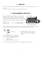
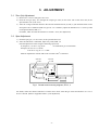
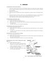
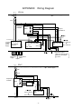
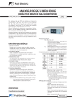
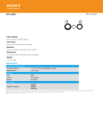
Service Manual
ZIRCONIA OXYGEN
DETECTOR SERVICE
MANUAL
TYPE: ZFK 3, 4, 7
TN5A0281a-E
CONTENTS
1. PREFACE .........................................................................................................................................2
2. MEASUREMENT PRINCIPLE..........................................................................................................2
3. ADJUSTMENT .................................................................................................................................3
3.1 Zero (Air) Adjustment ....................................................................................................................... 3
3.2 Span Adjustment .............................................................................................................................. 3
4. TROUBLE CHECK SHEET ..............................................................................................................4
5. REPAIR.............................................................................................................................................5
APPENDIX Wiring Diagram.................................................................................................................6
Output characteristic table................................................................................................7
-1-
1. PREFACE
This service manual explains repair and adjustment procedure of the Zirconia oxygen detector (ZFK 3, 4, 7) as a
single unit.
This manual is intended for use with the instruction manual (INZ-TN4ZFK3).
2. MEASUREMENT PRINCIPLE
When yttria-stabilized zirconia ceramic is heated to hightemperature, only the oxygen ion becomes a movable solid
electrolyte. In a zirconia element, the both sides of which are fitted
with a platinum electrode, the electrode reactions in the following
expressions occur for the oxygen concentrations P1 and P2 (P1 >
P2).
Electrode of P1 side
O2 + 4e → 20¯ ¯ (negative electrode)
Electrode of P2 side
20¯ ¯→ O2 + 4e (positive electrode)
Heater
Insulating
material
Casing
Filter
Air P1
P2
Measured
gas
Output
Electrode
Fig.1
Zirconia element
Detector structure
That is, the oxygen ion moves from the P1 side, where oxygen concentration is higher, to P2 side, where it is lower.
This energy for moving the ion generates the electric force (E) indicated in the following expression.
E=
P (O )
RT
1n 1 2 (V)
4F
P2 (O 2 )
=50.74 log
E
P1 (O2)
P2 (O2)
R
T
F
P1 (O 2 )
(mV) (at 800 °C)
P2 (O 2 )
: Electric force
: Comparative (Air) oxygen concentration
: Oxygen concentration in the measured gas
: Gas constant 8.3144 (J·moℓ-1·K-1)
: Absolute temperature
: Faraday constant 9.649 × 10⁴ (c·moℓ-1)
∗ Coefficient 50.74 is the value when the
zircornia element is 750°C. (The sensor unit
becomes 750°C with 800°C temperature
control.)
Therefore, unknown oxygen concentration P2 (O2) can be calculated from the electric force (E).
-2-
3. ADJUSTMENT
3.1 Zero (Air) Adjustment
1) Remove the 3 screws fixing the case cover.
2) Feed the zero gas (Dry Air) through the sample gas inlet (on the lower side of the main unit) at the
specified flow rate (0.5L /min).
3) After the voltage indication between the external terminals block (4) and (5) (the terminal block on the
front panel 7P) is stabilized (feed zero gas for 2 to 3 minutes), adjust the indication to 0 ± 1mV by VRZ
on the printed board; ZFK 3, 4.
For ZFK7, make sure that the indication is within ± 3mV. (No adjustment)
3.2 Span Adjustment
1) Feed the span gas (1 to 2% O2/N2) at the specified flow rate.
2) After the indication is stabilized, adjust it by VRS; ZFK 3, 4
Find the adjustment value using the following expression.
E (Output:V) = 0.3812 × log 21/Px
Px:Calibration gas concentration
Example) In case of 1.1% O2/N2
E=0.3812 × log 21/1.1 = 0.488v
Make an adjustment with the VRs control so that 0.488V is obtained.
1
2
SSR
2
CN3
1
C1
R5
CN1 C3
ZD2
ZD1
ZD4
ZD3
8
C2
R1
1
Fig.2
TK4B5692R2
3
4
VRZ 3
R8
R2
R7
R3
CN2
1
3
1
Zero VR
VRZ
01
C4
JAPAN
R4
VRS
1
6
Span VR
VRS
Printed board mounting diagram; ZFK 3, 4
For ZFK7, make sure that the indication is within 50 to 70mV when the gas with concentration of 1 to 2 %
O2/N2 is flowed. (Refer to Appendix Table 2.) (No adjustment)
-3-
4. TROUBLE CHECK SHEET
Phenomena
Slow response
Cause
Sensor element
deterioration
Sample gas is not
supplied or output
is abnormal.
Sensor outlet is
clogged with
crystallized sulfate
mist.
Output is unstable
ZFK 3, 4
Disconnection of
connector or poor
contact
Disturbance noise
Sensor element
deterioration
Output is not
deflected or
remains the same.
Fuse is blown out or
power is not
supplied.
ZFK 3, 4
Disconnection of
connector or poor
contact
Sensor is defective.
Solid relay is
defective.
Printed board is
defective.
Output swings
over.
ZFK 3, 4
Constant voltage
power supply is
defective.
Temperature
controller is
defective.
Measuring range is
exceeded.
Checking methods (normal value)
Change over between zero and span
gas and check if 60 seconds or longer
is needed for 90% response.
Visually check for clogging of the
outlet of the gas introduction case.
Check if the connector is
disconnected or move the connector
part to check for the indication
change.
Check if output is hunting.
Flow zero/span gas continuously for
10 minutes or so, and observe the
indication status.
Check the fuse and the supply
voltage specification.
Protective measures
Replace
Remove the clogging.
Replace with a gas
introduction case
(provided with gas
outlet pot).
Repair
Eliminate noise.
Replace the sensor
element.
Replace the fuse or
check the power supply.
Check if the connector is
disconnected or move the connector
part to check for the indication
change.
Change over between zero and span
gas and check for the indication
change. Remove one end of the
sensor terminal block (3) – (4), and
check for continuity. The range
should be within 2 to 3 Ω.
When 24V DC is applied to the outer
end (7) – (8) (-), check if AC power
between (1) – (2) on the sensor
element is turned on or off. (Check
with a tester.)
Change over between zero and span
gas and check if the voltage value
between the sensor outer end (5) –
(6) (+) indicates as shown below.
Air: ± 3mV or lower
1 to 2% O2/N2: 50 to 70mV.
Check if the CN2 of the constant
voltage power supply indicates
12 ± 0.1V.
Repair
Check if the temperature indication is
constant in a range of 800 ± 5 °C.
Replace the temperature
controller.
Flow measured gas after zero/span
calibration.
Review the
specifications.
-4-
Replace the sensor
element.
Replace the printed
board or the solid relay.
Replace the printed
board or the solid relay
or sensor element.
Replace the constant
voltage power supply.
5. REPAIR
(1) Replacement of the sensor element
1)
Change the measuring gas line to the Air atmosphere and then turn off the power switch. When the
device is operating, install an oxygen meter by bypass piping. Leave the device for about 30 minutes
till it cools down.
2)
Remove the case cover (a).
3)
Remove the 6 wires connected to the sensor terminal block (b) and the 3 M4 screws fixing the sensor
(c).
4)
Pull out the sensor (d) from the sensor case (e), and assemble the new sensor in reverse order of
disassembly. After wiring is checked, perform energization and running to calibrate zero/span.
When replacing the sensor element, also replace the packing with a new one.
(2) Replacement of the sensor case
1), 2) Follow the procedure in Item (1).
3)
Remove the 3 M4 screws fixing the sensor (c).
4)
Remove the 2 screws fixing the sensor case from the bottom of the main unit, and remove the sensor
case from the top.
5)
Assemble a new sensor in reverse order of disassembly.
(3) Replacement of the printed board (ZFK 3, 4)
1), 2) Follow the procedure in Item (1).
3)
Remove the 8 wires connected to the terminal block of the printed board and 3 screws fixing the
printed board.
4)
Assemble a new printed board in reverse order of disassembly. Perform energization and running to
calibrate zero/span.
(4) Replacement of the temperature controller
1), 2) Follow the procedure in Item (1).
3)
Remove the 2 screws from the top of the temperature controller and the socket from the backside, and
pull out the controller forward.
4)
Assemble a new temperature controller in reverse order of disassembly.
(5) Replacement of the constant voltage power supply
(ZFK 3, 4)
1), 2) Follow the procedure in Item (1).
3)
Remove the 5 wires and the 2 side fixing screws
connected to the upper terminal block of the
constant voltage power supply (g), and remove
the constant voltage power supply.
4)
Assemble a new constant voltage power supply
in reverse order of disassembly.
& '
! "
( $%
Fig.3
-5-
# $%
! "
Internal diagram of the oxygen analyzer
APPENDIX
Wiring Diagram
ZFK3,4
R T
Power supply
SW
F. 3A
85 to 265V AC
85 to 265V AC
Temperature 11 10
controller
PXR4
2
1
Approx.
8mV/800˚C
5
4
7 8
mV
85 to 265V AC
O2
DCV
6 7
OUT
CN1
Amp. P.C.B
8
1
SSR
IN
2 3
4 5
6 7
R T E
101
102
103
104
1
ZFK
2
CN3
C
Power supply
SW
F. 3A
85 to 265V AC
7 8
2
1
4
3
2
1
SSR
104
103
100 to 115V AC
1
2 3
Heat
4 5
R
6
OUT
C
ZFK
200 to 220V AC
Temperature
alarm
102
101
O2
OUT
100 to 115V AC
200 to 220V AC
Temperature alarm
When the setting value
(800˚C) is exceeded
by ±20˚C
Output
ZFK7
5
4
6
1
Main power
Temperature
supply
alarm
Output
Temperature 11 10
controller
PXR4
4 5
R
Heat
+ -
R T
2 3
-6-
104
IN
4 5
103
2 3
102
1
0
101
Constant
AC AC 12V
voltage
DC POWER
power
SUPPLY
supply
C
APPENDIX TABLE 1
ZFK 3, 4 Zirconia oxygen Analyzer
Output characteristic table (ZFK 3, 4 output)
%O2
OUTPUT (mV)
0.05
1000
0.1
885.3
0.5
618.8
1.0
504.0
2.0
389.3
3.0
322.2
4.0
274.5
5.0
237.6
6.0
207.4
7.0
181.9
8.0
159.8
9.0
140.3
10.0
122.8
11.0
107.1
E (OUTPUT : V) = 0.3812 log 21/O2%
%O2
12.0
13.0
14.0
15.0
16.0
17.0
18.0
19.0
20.0
21.0
22.0
23.0
24.0
25.0
OUTPUT (mV)
92.7
79.4
67.1
55.7
45.0
35.0
25.5
16.6
8.8
0.0
-7.7
-15.1
-22.1
-28.9
APPENDIX TABLE 2
ZFK 3, 4, 7 Zirconia oxygen Analyzer Detector Output characteristic (internal sensor)
%O2
OUTPUT (mV)
0.01
168.57
0.02
153.3
0.03
144.36
0.04
138.02
0.05
133.1
0.1
117.83
0.2
102.56
0.3
93.62
0.4
87.28
0.5
82.36
0.6
78.35
0.7
74.95
0.8
72.01
0.9
69.41
1.0
67.09
2.0
51.82
3.0
42.88
4.0
36.54
5.0
31.62
6.0
27.61
E (OUTPUT : mV) = 50.74 log 21/O2%
%O2
7.0
8.0
9.0
10.0
11.0
12.0
13.0
14.0
15.0
16.0
17.0
18.0
19.0
20.0
20.6
21.0
22.0
23.0
24.0
25.0
-7-
OUTPUT (mV)
24.21
21.27
18.67
16.35
14.25
12.33
10.57
8.93
7.41
5.99
4.66
3.40
2.21
1.08
0.4238
0
-1.025
-2.005
-2.943
-3.84