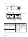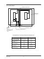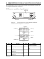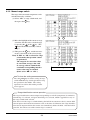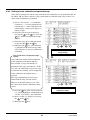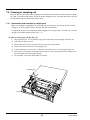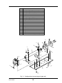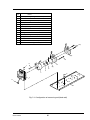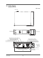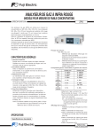
1
ZRE
NDIR/02
USER’S
MANUAL
1312 West Grove Avenue
Orange, CA 92865-4134
Phone: 714-974-5560 Fax: 714-921-2531
www.gasanalyzers.com
PREFACE
Thank you very much for purchasing Fuji’s Infrared Gas Analyzer (Type: ZRE).
• Be sure to read this instruction manual carefully before performing installation, wiring,
operation, and maintenance of the analyzer. Improper handling may result in accidents or
injury.
• The specifications of this analyzer are subject to change without prior notice for further
product improvement.
• Modification of this analyzer is strictly prohibited unless a written approval is obtained
from the manufacturer. Fuji will not bear any responsibility for a trouble caused by such a
modification.
• The person who actually operates the analyzer should keep this instruction manual.
• After reading through the manual, be sure to keep it near at hand for future reference.
• This instruction manual should be delivered to the end user without fail.
Manufacturer
: Fuji Electric Instrumentation Co., Ltd.
Type
: Described in the nameplate on main frame
Date of manufacture
: Described in the nameplate on main frame
Country of manufacture : Japan
© Fuji Electric Systems Co., Ltd. 2007
Issued in May, 2007
Request
• No part or the whole of this manual may be reproduced without
written permission of Fuji.
Rev. 1st edition, June, 2007
• Description in this manual is subject to change without prior
notice for further improvement.
Rev. 3rd edition, February, 2008
INZ-TN1ZRE-E
i
Rev. 2nd edition, September, 2007
CAUTION ON SAFETY
To operate the analyzer properly, be sure to read “Caution on Safety” carefully.
• The descriptions listed here provide important information on safety. Be sure to observe them at all
times. Those safety precautions are classified into 3 levels, “DANGER,” “CAUTION” and “PROHIBITION.”
DANGER
Improper handling may cause dangerous situations that may
result in death or serious injury.
CAUTION
Improper handling may cause dangerous situations that may
result in medium-level troubles, minor injury, or property
damage.
PROHIBITION
Items which must not be done are indicated.
Caution on installation and transport of gas analyzer
DANGER
CAUTION
• The unit is not of explosion-proof specifications. Do not use
it in an atmosphere of explosive gases. Otherwise, serious accidents such as explosion or fire may result.
• For installation, observe the rule on it given in the instruction
manual, and select a place where the weight of analyzer can
be endured. Installation in an inadequate place may cause
turnover or fall, resulting in injury.
• Be sure to wear protective gloves when lifting the analyzer.
Lifting it with bare hands may result in injury.
• Be sure to fix the casing before transporting the analyzer.
Transportation in unstable state may result in injury.
• The gas analyzer is heavy. Two or more persons should carry
it, while exercising due care. Otherwise, unexpected harm to
your body or injury may result.
• Take care not to let cable chips and other foreign objects enter
the unit during installation work. Otherwise, fire, failure, or
malfunction may result.
ii
INZ-TN1ZRE-E
Caution on piping
DANGER
Be sure to observe the following precautions while installing
piping. Improper piping may result in gas leakage.
If the leaking gas contains a toxic component, serious accidents may result. If it contains combustible gases, explosion
or fire may result.
• Connect pipes correctly referring to the instruction manual.
• Discharge the exhaust gas outdoors to prevent it from remaining within the sampling device or indoors.
• Relieve the exhaust gas from the analyzer to the atmospheric
pressure to prevent buildup of undesirable pressure to the analyzer. Otherwise, piping within the analyzer may be disconnected, resulting in gas leakage.
• Use pipes and pressure reducing valves to which no oil/grease
is attached to the piping. Otherwise, fire may result.
Caution on wiring
CAUTION
• Be sure to turn off the power before installing wiring. Otherwise, electric shock may result.
• Be sure to perform protective earth connection. Otherwise,
electric shock or failure may result.
• Select a proper wiring material that satisfies the ratings of the
instrument. Otherwise, electric shock or fire may result.
• Be sure to connect a power supply of correct rating. Otherwise, fire may result.
Caution on use
DANGER
CAUTION
• Be sure to read the instruction manual for reference gases before handling reference gases such as calibration gas to use them
properly.
• Leaving the analyzer unused for a long time or restarting it
after long-term suspension requires procedures different from
normal operation or suspension procedures. Be sure to follow
the instructions in each instruction manual. Otherwise, intended
performance may not be achieved. Besides, accidents or injury
may result.
• Do not operate the analyzer for a long time with its door left
open. Otherwise, dust, foreign matter, etc. may stick on internal
walls, thereby causing faults.
INZ-TN1ZRE-E
iii
Caution on use
PROHIBITION
• Do not touch the input/output terminals with metal or finger.
Otherwise, electric shock or injury may result.
• Do not smoke or use flames near the analyzer. Otherwise, fire
may result.
• Do not allow water to enter the analyzer. Otherwise, electric
shock or internal fire may result.
Caution on maintenance and check
DANGER
CAUTION
• Before performing work with the cover of the analyzer kept
open for maintenance and check, be sure to purge completely
not only within the analyzer but also measuring gas lines with
nitrogen or air. Otherwise, poisoning, fire, or explosion may
result due to gas leakage.
Be sure to observe the following to perform work safely, avoiding electric shock or injury.
• Remove the watch and other metallic objects before work.
• Do not touch the instrument with wet hands.
• If the fuse is blown, eliminate the cause and replace it with the
one of the same capacity and type. Otherwise, electric shock or
accidents may result.
• Do not use replacement parts other than those specified by the
manufacturer. Otherwise, intended performance may not be
achieved. Besides accidents or failures may result.
• Dispose replacement parts such as maintenance parts as incombustibles according to the local waste disposal regulations.
Others
CAUTION
• If the cause of any fault cannot be identified by referring to the
instruction manual, be sure to contact your dealer or Fuji’s technician in charge of adjustment. Disassembling the instrument
carelessly may result in electric shock or injury.
iv
INZ-TN1ZRE-E
CONTENTS
PREFACE ......................................................................................................................i
CAUTION ON SAFETY ............................................................................................ii
CONTENTS ................................................................................................................. v
1.
OVERVIEW .......................................................................................................... 1
2.
NAME OF DELIVERED ITEMS AND EACH PARTS ...................................... 2
3.
4.
5.
6.
2.1
Confirmation of delivered items............................................................................. 2
2.2
Name and description of analyzer .......................................................................... 3
INSTALLATION .................................................................................................. 4
3.1
Installation conditions ............................................................................................ 4
3.2
Installation .............................................................................................................. 5
3.2.1 Installation of analyzer main frame ............................................................... 5
3.3
Piping ..................................................................................................................... 6
3.4
Sampling ................................................................................................................ 8
3.4.1 Conditions of sampling gas............................................................................ 8
3.4.2 Sampling gas flow .......................................................................................... 8
3.4.3 Preparation of standard gas ............................................................................ 8
3.4.4 Purging of instrument inside ......................................................................... 8
3.4.5 Pressure at sampling gas outlet ...................................................................... 9
3.4.6 Example configuration of gas sampling system ............................................ 9
3.5
Wiring................................................................................................................... 10
OPERATION ...................................................................................................... 16
4.1
Preparation for operation ..................................................................................... 16
4.2
Warm-up operation and regular operation ........................................................... 16
DESCRIPTION OF DISPLAY AND OPERATION PANELS .......................... 17
5.1
Name and description of operation panel ............................................................ 17
5.2
Overview of display and operation panels ........................................................... 18
5.3
Outline of display screen...................................................................................... 19
5.4
Basic operation ..................................................................................................... 22
SETTING AND CALIBRATION....................................................................... 23
6.1
Switch of range .................................................................................................... 23
6.1.1 Setting of range switch mode....................................................................... 23
6.1.2 Manual range switch .................................................................................... 24
6.2
Calibration setting ................................................................................................ 25
6.2.1 Setting of calibration concentration ............................................................. 25
6.2.2 Setting of manual zero calibration ............................................................... 27
6.2.3 Setting of calibration range .......................................................................... 29
6.2.4 Setting of auto calibration component/range ............................................... 30
INZ-TN1ZRE-E
v
7.
6.3
Alarm setting ........................................................................................................ 32
6.3.1 Setting of alarm values................................................................................. 32
6.3.2 Hysteresis setting ......................................................................................... 34
6.4
Setting of auto calibration .................................................................................... 35
6.4.1 Auto calibration ........................................................................................... 35
6.4.2 Forced run/stop of auto calibration .............................................................. 38
6.5
Setting of auto zero calibration ........................................................................... 40
6.5.1 Auto zero calibration ................................................................................... 40
6.5.2 Forced run/stop of auto zero calibration ...................................................... 42
6.6
Parameter setting .................................................................................................. 44
6.7
Maintenance mode ............................................................................................... 50
6.8
Calibration ............................................................................................................ 55
6.8.1 Zero calibration ............................................................................................ 55
6.8.2 Span calibration ........................................................................................... 56
MAINTENANCE ............................................................................................... 57
7.1
Daily check .......................................................................................................... 57
7.2
Daily check and maintenance procedures ............................................................ 57
7.3
Cleaning of sampling cell .................................................................................... 58
7.3.1 Disassembly and assembly of sampling cell................................................ 58
7.3.2 How to clean cell ......................................................................................... 63
8.
ERROR MESSAGE ............................................................................................ 64
9.
SPECIFICATIONS ............................................................................................. 67
9.1
General specifications .......................................................................................... 67
9.2
Code symbols ....................................................................................................... 70
9.3
Outline diagram.................................................................................................... 73
vi
INZ-TN1ZRE-E
1. OVERVIEW
This infrared gas analyzer (type: ZRE) measures the concentration of NO, SO2, CO2, CO and CH4 contained in sampling gas on the principle that different atomic molecules have an absorption spectrum in the
wave band of infrared rays, and the intensity of absorption is determined by the Lambert-Beer law.
Since this instrument incorporates a compact O2 sensor, it allows measuring up to 5 components simultaneously by using the built-in O2 sensor (up to 4 components if O2 sensor is excluded).
Furthermore, use of a microprocessor or large sized liquid crystal display realizes improvement of operability, accuracy and multi-functions.
This instrument is optimum for measuring combustible gas exhausted from boilers or incinerators, and it
is effective for steel gas analysis [blast furnace, steel converter, thermal treatment furnace, sintering (Pellet
equipment), coke furnace], storage and maturity of vegetable and fruit, biochemistry (microbe), [fermentation], air pollution [incinerator, exhaust gas desulfurization, denitration], automotive emission (excluding
tester), protection against disasters [detection of explosive gas and toxic gas, combustion gas analysis of
new building material], growth of plants, chemical analysis [petroleum refinery plant, petroleum chemistry plant, gas generation plant], environment [landing concentration, tunnel concentration, parking lot,
building management] and various physical and chemical experiments.
INZ-TN1ZRE-E
1
2. NAME OF DELIVERED ITEMS AND EACH PARTS
2.1 Confirmation of delivered items
ZRE- GAS ANALYZER
MODE ZERO SPAN
Analyzer: 1 unit
ENTER
FL1
FL2
POWER
ESC
Fuse: 2 pcs
Standard: IEC127-2
Size: ø5 × 20mm
Rating: 250V/2A delay type
Part No.: TK7L7571P3
Analog output connector: 1
Fixing screws: 2
25 pin D-sub connector (male)
Part No.: TK7N3059P8
M2.6 × 4mm
Instruction Manual
Instruction manual (this catalog): 1 copy
(INZ-TN1ZREa)
CD-ROM: 1
(When provided with communication
function)
NDIR TYPE
INFRARED
GAS
ANALYZER
TYPE : ZRE
INZ-TN1ZRE
b-E
Panel mounting bracket: 4 pcs
(When panel mounting is specified)
Part No.: TK7N7944P2
External input connector: 1
(External O2 analyzer and External
zirconia O2 analyzer are specified)
Part No.: TK7N3061P14
Digital input/output connector: 3 max.
with the number of DIO
Fixing screws: 6 max.
(When digital input/output function is
specified)
Max.
3 sets
RS-485 connector: 1
Fixing screws : 2
(When provided with communication
function)
25 pin D-sub connector (male)
Part No.: TK7N3059P8
M2.6 × 4mm
9 pin D-sub connector (male)
Part No.: TK7N3059P9
M2.6 × 4mm
2
INZ-TN1ZRE-E
2.2 Name and description of analyzer
③ Flow meter (2 systems)
ZRE-
GAS ANALYZER
MODE
ZERO
SPAN
ENTER
< Front panel >
FL1
FL2
ESC
POWER
④ USB connector
① Power switch
② Display/operation panel
⑤ Purge gas inlet
⑪ Communication connector (RS-485)
⑥ Sampling gas inlet (2 systems)
⑫ Analog output connector (A/O)
(D-sub25 pin)
⑩ External input
connector
⑦ Sampling gas outlet (2 systems)
DIO3
RS485
A/O
PURGE
A/I
INLET1
OUTLET1
Made in Japan
INFRARED GAS ANALYZER
< Rear panel >
00000-
OUTPUT DC
POWER AC100V∼C240V
SER.NO.
MFD
INLET2
OUTLET2
F
TYPE
DIO2
50/60 Hz VA
U SE
DIO1
FUSE
250V T 2A
Fuji Electric Systems Co.,Ltd.
⑧ Fuse
⑨ Power terminal block
⑬ Digital input/output connector (DIO1 to 3)
(D-sub25 pin)
Fig. 2-1
Name
Description
Name
Description
① Power switch
Used for ON/OFF the analyzer.
⑧ Fuse
Fuse inside
② Display/operation
Liquid crystal display and keys
for setting various functions.
⑨ Power terminal
For connecting to the power
supply line.
For checking the flow rate of
sampling gas.
⑩ External input
For connecting to the USB
cable.
⑪ Communication
For connecting to the purge gas
tube.
⑫ Analog output
panel
③ Flow meter
④ USB connector
⑤ Purge gas inlet
⑥ Sampling gas inlet
⑦ Sampling gas
outlet
INZ-TN1ZRE-E
block
connector
connector
connector
(D-sub25 pin)
For connecting to the output of
externally installed O2 analyzer.
RS-485 connector for
communication.
Connector for the analog output
For connecting to the measuring
gas tube.
⑬ Digital input/output Connector for the digital
connector
input/output
For connecting to the exhaust
(D-sub25 pin)
line.
3
3. INSTALLATION
DANGER
This unit is not explosion-proof type. Do not use it in a place with explosive gases to prevent
explosion, fire or other serious accidents.
CAUTION
• Entrust the installation, movement or re-installation to a specialist or the supplier. A poor
installation may cause accidental tipover, electric shock, fire, injury, etc.
• The gas analyzer is heavy. It should be installed with utmost care. Otherwise, it may tipover
or drop, for example, causing accident or injury.
• For lifting the gas analyzer, be sure to wear protective gloves. Bare hands may invite an
injury.
• This unit should be installed in a place which conforms to the conditions noted in the instruction manual. Otherwise, it may cause electric shocks, fire or malfunction of the unit.
• During installation work, care should be taken to keep the unit free from entry of cable chips
or other foreign objects. Otherwise, it may cause fire, trouble or malfunction of the unit.
3.1 Installation conditions
To install the analyzer for optimum performance, select a location that meets the following
conditions;
(1) This instrument is system built in type. This instrument should be used while embedded
in a panel, locker, or enclosure of steel sheet.
(2) Use this instrument indoors.
(3) A vibration-free place
(4) A place which is clean around the analyzer.
(5) Power supply
Rated voltage
: 100V to 240V AC
Operating voltage
: 85V to 264V AC
Rated frequency
: 50/60 Hz
Power consumption
: 100 VA max.
(6) Operation conditions
Ambient temperature
: -5° to 45°C (max. 40°C when two optial units are used, and the
power supply is more than 200V AC)
Ambient humidity
: 90 % RH or less, no condensation
4
INZ-TN1ZRE-E
3.2 Installation
3.2.1 Installation of analyzer main frame
Installation methods for the analyzer main unit are divided into 2 types;
Type
External dimensions
Mounting dimensions
(Unit : mm)
Mounting method
19-inch rack
mounting
GAS ANALYZER
ZERO
SPAN
ENTER
FL2
ESC
A
MODE
FL1
132.5
ZRE-
M6
POWER
435
450 or more
Support
483
465
“A” : 57.2 (EIA) or 50 (JIS)
Panel mounting
Panel cutout dimensions
Mounting bracket
ZERO
ENTER
FL1
FL2
ESC
SPAN
126
MODE
+2
-0
GAS ANALYZER
132.5
ZRE-
POWER
436
443
+2
-0
Support
Note) • The analyzer weight should be supported at the bottom of the casing.
• The analyzer should be installed in a place where ambient temperature is within -5 to 45°C (max.
40°C when two optial units are used, and the power supply is more than 200V AC), and temperature fluctuation during using is minimum.
• Where vibration is unavoidable, protect the analyzer from vibrating.
For example, protection rubber is installed between the analyzer and support, or the analyzer’s
front panel and mounting panel.
INZ-TN1ZRE-E
5
3.3 Piping
Observe the following when connecting the gas tube.
•
Piping should be connected to the gas inlets and outlets at the rear panel of the analyzer.
•
Use a corrosion resistant tube of Teflon, stainless or polyethylene to connect the instrument to
a sampling system. Even if there is a danger of corrosion, refrain from using a tube of rubber
or soft vinyl. The instrument provides inaccurate indication due to gas absorption by piping
materials.
•
Pipe connection port is Rc1/4 female thread (or NPT1/4). Piping should be cut as short as
possible for a quick response. About 4 mm inner diameter is recommended.
•
Entry of dust into the instrument may result in defective operation. Use a clean piping or coupling.
Purge gas inlet
Sampling gas inlet 1
Sampling gas outlet 1
DIO3
RS485
A/O
PURGE
A/I
INLET1
OUTLET1
Made in Japan
INFRARED GAS ANALYZER
00000-
INLET2
OUTPUT DC
POWER AC100V∼C240V
SER.NO.
MFD
OUTLET2
F
TYPE
DIO2
50/60 Hz VA
U SE
DIO1
FUSE
250V T 2A
Fuji Electric Systems Co.,Ltd.
Sampling gas inlet 2
For special case only
Sampling gas outlet 2
Sampling gas inlet:
Attach the gas tube to introduce gas to be measured such as one that has
completed dehumidification process and standard gases for zero and span
calibration to this inlet.
Gas flow to be introduced should be constant within the range of 0.5 L/min
±0.2 L/min.
Sampling gas outlet: Exhaust measured gas through the outlet. Attach the tube to exhaust measured gas outdoors or to the atmosphere.
Purge gas inlet:
It is used for purging the inside of the total gas analyzer.
Use dry gas N2 or instrumentation air for purge gas. (Flow rate is 1L/min or
more, and dust or mist is unallouwable.)
6
INZ-TN1ZRE-E
Internal piping diagram
Optical unit 2 (IR Unit 2)
Optical unit 1
(IR Unit 1)
Built-in
O2 sensor
INLET1
OUTLET1
Sampling gas outlet
Sampling cell
Note)
2 cells may be used
by combination of
range.
Sampling gas inlet
Correspondence of measured components and optical units
Measuring components
Optical unit 1
Optical unit 2
Each component
None
2-components for
CO2/CO
CO2/CO
None
2-components for
NO/CO, NO/SO2
NO
NO
CO
SO2
3-components for
NO/SO2/CO
NO
SO2/CO
4-components for
NO/SO2/CO2/CO
NO/CO
SO2/CO2
1-component for NO,
SO2, CO2, CO and CH4
INZ-TN1ZRE-E
7
3.4 Sampling
3.4.1 Conditions of sampling gas
(1) Dust contained in the sampling gas should be completely removed with a filter. For the final
stage filter, use a filter that allows removing dust particles of 0.3μm.
(2) Dew point of the sampling gas must be lower than the ambient temperature to avoid occurrence of drain in the gas analyzer. If vapor is contained in the sampling gas, dew point should
be lowered to 2˚C by using a dehumidifier.
(3) If SO3 mist is contained in the sampling gas, use a mist filter or cooler to remove SO3 mist.
Other mists should be removed by using a mist filter or gas dryer.
(4) Corrosive gases such as Cl2, F2 and HCl, if they are contained in the sampling gas in considerable amounts, will shorten the life of instruments.
(5) Temperature of the sampling gas should be within 0 to 50˚C. Pay attention not to flow hot gas
directly into the instrument.
3.4.2 Sampling gas flow
Flow of sampling gas should be 0.5L/min ± 0.2L/min.
Avoid flow fluctuation during measurement.
Observe the flow reading by a flowmeter provided as shown in the example of the sampling system configuration (Item 3.4.6).
3.4.3 Preparation of standard gas
Routine calibration is required by standard gas for keeping this instrument under normal operation
condition (once a week). Prepare a standard gas cylinder for zero calibration and span calibration.
Analyzer without O2
measurement
Analyzer with built-in O2
sensor
Analyzer with external zirconia O2 sensor
Zero gas
N2 gas
N2 gas
Dry air
Span gas other
than for O2
measurement
Gas with concentration of 90% or more
of full scale
Gas with concentration of
90% or more of full scale
Gas with concentration of 90%
or more of full scale
Gas with concentration of
90% or more of full scale
or atmospheric air (21%)
O2 gas of 1 to 2%
Span gas for O2
measurement
3.4.4 Purging of instrument inside
The inside of instrument need not be purged generally except for the following cases.
(1) A combustible gas component is contained in the sample gas.
(2) Corrosive gas is contained in the atmospheric air at the installation site.
(3) The same gas as the sample gas component is contained in the atmospheric air at the installation site.
In such cases as above, the inside of analyzer should be purged with the air for instrumentation
or dry N2.
Purging flow rate should be about 1L/min.
If dust or mist is contained in purging gas, it should be eliminated completely in advance.
8
INZ-TN1ZRE-E
3.4.5 Pressure at sampling gas outlet
Pressure at the sampling gas outlet should be adjusted to the atmospheric pressure.
3.4.6 Example configuration of gas sampling system
The following illustrates a typical system configuration for five component gas measurement for
monitoring combustion exhaust gas from boiler, refuse incinerator, etc.
Contact Fuji Electric for system configuration matching the particular use or further information.
(1) Gas extractor
(11) NO2/NO (7) Membrane
converter
filter
φ10/φ8
Teflon
tube
15
r
ge
ar
l
or
ZRE unit
(4) Gas aspirator
(2) Mist filter
2-way
solenoid
valve
(8) Flowmeter
Infrared gas
analyzer
main frame (O2)
(5)
Electronic
gas cooler
ZERO NO
SO2
CO2
CO
(6)
Solenoid
valve
O2
Pressure
reducing valve
(3) Safety
drain
trap
Air
NO
/N2
SO2
/N2
CO2
/N2
CO
/N2
O2
/N2
(10)
Zirconia
O2 senor
(ZFK7)
(9) Standard gas
Exhaust
Drain
Name
(1) Gas extractor
(2) Mist filter
(3) Safety drain trap
(4) Gas aspirator
(5) Electronic gas
cooler
(6) Solenoid valve
(7) Membrane filter
INZ-TN1ZRE-E
Description
Name
Gas extractor with a heating
(8) Flowmeter
type stainless steel filter of
standard mesh 40µm
Removes drain, mist, and dust. (9) Standard gas
The safety drain trap is divided
into two rooms for positive and
negative pressure. It monitors and adjusts the sample gas
pressure.
For aspiration of the sample gas (10) Zirconia O2
sensor
Dries the moisture in the
sample gas to a dew point of
approx. 2˚C.
Used for introducing the calibration gas.
PTFE filter used to eliminate
fine dust particles.
(11) NO2/NO converter
9
Description
Adjusts and monitors the flow
rate of the sample gas.
Reference gas used for calibrating zero and span of the
analyzer, depending on the
measured gas.
External zirconia oxygen
sensor used for measuring
the oxygen concentration in
sample gas.
(This is not necessary in case
when O2 sensor is built-in.)
Added to NOx analyzer.
A special catalyst material for
efficient conversion of NO2
gas to NO is used.
3.5 Wiring
CAUTION
• Be sure to turn off the power before installing wiring. Otherwise, electric shock may result.
• Be sure to perform protective earth connection. Otherwise, electric shock or failure may
result.
• Select a proper wiring material that satisfies the ratings of the instrument. Otherwise, electric shock or fire may result.
• Be sure to connect a power supply of correct rating. Otherwise, fire may result.
The power terminal block and external input/output connector is provided at the rear panel. Refer
to the following.
External input connector (A/I)
Communication connector (RS-485)
Analog output connector (A/O)
DIO3
RS485
A/O
PURGE
A/I
INLET1
OUTLET1
Made in Japan
INFRARED GAS ANALYZER
00000-
OUTPUT DC
POWER AC100V∼C240V
SER.NO.
MFD
INLET2
OUTLET2
F
TYPE
DIO2
50/60 Hz VA
U SE
DIO1
FUSE
250V T 2A
Fuji Electric Systems Co.,Ltd.
Digital input/output connector
(DIO 1 to 3)
Power terminal block
(1) Power supply (standard terminal 1 to 2)
Connect the given power supply to the power terminal, and connect the ground wire to the grounding terminal (standard terminal 3). Be sure to perform protective earth connection. Use solderless
terminals (for M3.5) for connection to the terminals (power and earth).
PE
3
N
2
Ground wire
L
1
Power supply
100 to 240V AC
CAUTION
After the wiring work, be sure to place the protective cover for the terminal blocks to assure
safety.
10
INZ-TN1ZRE-E
When noise source is in the vicinity
•
Avoid installing this instrument near an electrical unit (high frequency furnace or electric welder)
that generates much electrical noise. If using the instrument near such a noise generating unit is
unavoidable, use a different power line to avoid noise.
Main unit
power supply
•
Varistor or
spark killer
Mount a noise suppressor such as varister or spark killer
as shown at right figure to the noise generating unit when
noise is generated from relays or solenoid valves.
Mount the suppressor near the noise generating source, or
it will have no effect.
Install (connect)
near the source.
Noise
generating
source
(2) Analog output signal: Analog output connector (A/O)
Output signal : 4 to 20 mA DC or 0 to 1 V DC (selected when ordering)
Minus lines for the insulation and signal are common from the ground and internal circuit
Allowable load : 4 to 20 mA DC, 550Ω or less
0 to 1 V DC, 100kΩ or more
< Analog output > A/O connector
13
1
1
14
2
25
14
15
3
D-sub 25-pin female
16
4
Note) Display Ch number is same
as the AO number under
standard specifications.
17
5
18
6
19
7
20
8
21
9
22
10
23
11
24
12
25
13
AO1+
AO1AO2+
AO2AO3+
AO3AO4+
AO4AO5+
AO5AO6+
AO6AO7+
AO7AO8+
AO8AO9+
AO9AO10+
AO10AO11+
AO11AO12+
AO12NC
All the analog output signals of the instrument are not isolated individually. It is recommended to isolate the signals individually to eliminate the interference from the unnecessary signals
or the effect of external interference, especially leading the cable of more than 30 meters or to
outdoor.
INZ-TN1ZRE-E
11
(3) O2 sensor input: External input connector (A/I)
Input signal:
External zirconia O2 analyzer :
Zirconia O2 sensor signal (Fuji ZFK7 output)
External O2 analyzer
0 to 1 V DC (DC input resistor of 1MΩ or more)
:
< External input > A/I connector (O2 sensor input)
AI-
AI+
•
It is used when the external zirconia O2 analyzer or the external O2 analyzer is specified as
order.
•
Connect the dedicated connector (accessory) to the output of the external Zirconia analyzer or
the external O2 analyzer prepared separately.
•
In case of an external O2 analyzer, input a signal of 0 to 1 V DC with respect to O2 full scale
of the analyzer. The O2 concentration display, output, and O2 correction can be performed.
•
Do not connect when the built-in O2 analyzer is installed.
O2 sensor input is not isolated. It is recommended to isolate when an external O2 analyzer is
installed apart from this analyzer. Zirconia O2 sensor (Fuji ZFK7) should be installed at a location that is as close to this instrument as possible.
*
How to connect the O2 signal to the dedicated connector (accessory).
Turn
+
To O2 sensor
−
Solder the signal cable to the terminal.
12
INZ-TN1ZRE-E
(4) Contact input/output (DIO): digital input/output connector (DIO1 to 3)
Contact input signal : Voltage is applied from the external 12 to 24 V DC,
Photo-coupler insulation (from each DI and ground)
Contact capacity
: C contact relay output 24V/1A AC/DC resistive load
< Digital input/output > Connector for DIO 1 to 3 (option)
13
DIO1
DIO2
DIO3
connector connector connector
1
1
14
2
25
14
15
3
D-sub 25-pin female
16
4
Note) DIO 1 to 3 have the same internal circuit of the
17
connector.
5
18
6
19
7
20
Contents of digital input
signal
DI1
Remote hold
DI2
Average value reset
DI3
A. cal. start
DI4
A. zero. cal. start
DI5
Remote range Ch1
DI6
Remote range Ch2
DI7
Remote range Ch3
DI8
Remote range Ch4
DI9
Remote range Ch5
max 15mA
8
21
9
22
10
23
11
NC
com
NO
NC
com
NO
NC
com
NO
NC
com
NO
NC
com
NO
DI1+
DI1DI2+
DI2DI3+
DI3-
DI4+
DI4DI5+
DI5DI6+
DI6-
DI7+
DI7DI8+
DI8DI9+
DI9-
DO1
DO6
DO11
DO2
DO7
DO12
DO3
DO8
DO13
DO4
DO9
DO14
DO5
DO10
DO15
Digital input
OFF : 0V
ON : 12 to 24V DC
Digital output
max. contact load
rating 24V DC/1A
24
12
25
13
Contents of digital output signal
Independent on the
number of component
1-component analyzer
22th digit
A,C
B,E
D,F,G,H
B,D,E,F,G,H
B,D,E,F,G,H
DO1
Instrument error
Instrument error
Instrument error
Instrument error
Instrument error
DO2
Calibration error
Calibration error
Calibration error
Calibration error
Calibration error
DO3
A.cal.status
(A.cal.status)
(A.cal.status)
(A.cal.status)
DO4
For zero gas
(For zero gas)
(For zero gas)
(For zero gas)
DO5
For span gas Ch1
(For span gas Ch1)
(For span gas Ch1)
(For span gas Ch1)
(For span gas Ch2)
(For span gas Ch2)
2-component analyzer 3-component analyzer
DO6
(Alarm1)
(Alarm1)
DO7
(Alarm2)
(Alarm2)
(For span gas Ch3)
DO8
(Alarm3)
(Alarm3)
(Range identification Ch1)
DO9
(Alarm4)
(Alarm4)
DO10
(Alarm5)
(Alarm5)
(Range identification Ch1)
(Range identification Ch2)
Range identification Ch1
(Range identification Ch2)
(Range identification Ch3)
DO11
(Alarm1)
(Alarm1)
(Alarm1)
DO12
(Alarm2)
(Alarm2)
(Alarm2)
DO13
(Alarm3)
(Alarm3)
(Alarm3)
DO14
(Alarm4)
(Alarm4)
(Alarm4)
DO15
(Alarm5)
(Alarm5)
(Alarm5)
4-component analyzer
The items in the parentheses
may not be available depending on the selected type on
22th digit.
The normal open side (NO) of
digital output is close when
the function is active without
range ID.
In case of range ID, normal
open (NO) side is close with
Lo-range.
The normal close (NC) side is
close with Hi-range.
5-component analyzer
22th digit
B,E
D,F
G
H
B,E
D,F
G
DO1
Instrument error
Instrument error
Instrument error
Instrument error
Instrument error
Instrument error
Instrument error
DO2
Calibration error
Calibration error
Calibration error
Calibration error
Calibration error
Calibration error
Calibration error
DO3
A.cal.status
A.cal.status
A.cal.status
A.cal.status
A.cal.status
DO4
For zero gas
For zero gas
For zero gas
For zero gas
For zero gas
DO5
For span gas Ch1
For span gas Ch1
For span gas Ch1
For span gas Ch1
For span gas Ch1
DO6
For span gas Ch2
For span gas Ch2
For span gas Ch2
For span gas Ch2 Range identification Ch1
For span gas Ch2
DO7
For span gas Ch3 Range identification Ch1
For span gas Ch3
For span gas Ch3
For span gas Ch3 Range identification Ch2
For span gas Ch3
DO8
For span gas Ch4 Range identification Ch2
For span gas Ch4
For span gas Ch4
For span gas Ch4 Range identification Ch3
For span gas Ch4
DO9
Range identification Ch3
Range identification Ch1
For span gas Ch5 Range identification Ch4
For span gas Ch5
DO10
Range identification Ch4
Range identification Ch2
Range identification Ch5
DO11
(Alarm1)
(Alarm1)
(Alarm1)
(Alarm1)
(Alarm1)
Range identification Ch1
DO12
(Alarm2)
(Alarm2)
Range identification Ch1
(Alarm2)
(Alarm2)
(Alarm2)
Range identification Ch2
DO13
(Alarm3)
(Alarm3)
Range identification Ch2
(Alarm3)
(Alarm3)
(Alarm3)
Range identification Ch3
DO14
(Alarm4)
(Alarm4)
Range identification Ch3
Range identification Ch3
(Alarm4)
(Alarm4)
Range identification Ch4
DO15
(Alarm5)
(Alarm5)
Range identification Ch4
Range identification Ch4
(Alarm5)
(Alarm5)
Range identification Ch5
INZ-TN1ZRE-E
13
• Insulation output (from each DO and ground)
To avoid external interference, wiring of analog output signal, O2 sensor input and contact
input should be fixed separately from that of power supply and contact output.
Note) To avoid the effect of noise generated from external units, be sure to ground the analyzer
main unit.
(5) Communication: RS-485/USB connector
< RS-485 connector >
5
(GND)
1
1
6
RT×D+
2
9
6
7
RT×D-
3
D-sub 9-pin female
8
4
9
5
< USB > TYPE-B connector
(6) Timing of contact output for calibration
1) Manual calibration (See “Item 6.8 Calibration”.) (When the analyzer has auto calibration
function.)
• Zero calibration
ZERO
ENT Calibration end
ENT
on
Zero calibration
output
Calibration gas flow
off
Ch1 to 5 span
calibration output
off
Output hold function
Output signal hold
(with hold ON setting)
Hold extension time.
• Span calibration
SPAN
Zero calibration
output
When selecting
Ch2 using
DOWN and UP
keys.
ENT Calibration end
ENT
Ch1 span
calibration
Ch2 span
calibration
Calibration gas flow
Hold extension time.
Output hold function
Output signal hold
(with hold ON setting)
Note) The hold extension time
depends on the gas
flow time of the
automatic calibration
settings.
14
INZ-TN1ZRE-E
2) In case of automatic calibration
(example shown in Item 6.4.1, Automatic calibration settings)
Automatic
Ch1 span
Ch3 span
calibration
calibration
calibration
start
Ch4 span
Ch2 span
Zero calibration
calibration
calibration
Zero calibration output
Ch5 span
calibration
Zero gas
350 s
Ch1 span calibration output
Ch2 span calibration output
Ch1 span gas
350 s
Ch3 span calibration output
Ch4 span calibration output
Ch5 span calibration output
Automatic calibration contact
Output hold function
Hold
extension time.
(with hold ON setting)
INZ-TN1ZRE-E
15
4. OPERATION
4.1 Preparation for operation
(1) Tube and wiring check
Double-check if tubes of the gas sampling and exhaust ports are correctly connected.
Double-check for proper wiring.
4.2 Warm-up operation and regular operation
(1) Operation procedure
1) Turn ON the power switch on the left side when facing the front panel of the analyzer unit.
The measurement screen appears on the front display panel in 1 to 2 seconds.
2) Wait for about 4 hours until the instrument is warmed up.
About 4 hours are required until the instrument allows accurate measurement.
Note) When in warm-up, the concentration reading may be beyond.
upper limit of range.
But, it is not an error.
3) Setting of various set values
Perform the various settings according to “Item 6. Setting and Calibration”.
4) Zero calibration and span calibration
Perform zero/span calibration after warm-up operation.
Refer to “Item 6.8 Calibration”.
5) Introduction and measurement of measuring gas
Introduce the measuring gas into the analyzer unit before starting measurement.
16
INZ-TN1ZRE-E
5. DESCRIPTION OF DISPLAY AND OPERATION PANELS
This section describes the display unit and operation panel of the analyzer unit. It also explains the name
and description of function on the operation panel.
5.1 Name and description of operation panel
Display unit
ZRE-
GAS ANALYZER
MODE
ZERO
SPAN
ENTER
FL1
FL2
ESC
POWER
Power switch
• Display unit:
Operation panel
The measurement screen and the setting items are displayed.
• Operation panel: The configuration is as shown below.
⑦ ZERO key
① MODE key
MODE
ZERO
SPAN
⑧ SPAN key
⑥ ENT key
ENTER
③ UP key
② SIDE key
⑤ ESC key
ESC
④ DOWN key
Fig. 5-1
Name
Description
Name
① MODE key
Used to switch the mode.
② SIDE key
Used to change the selected item (by
⑥ ENT key
moving the cursor) and the numeral digit.
③ UP key
Used to change the selected item (by
moving the cursor) and to increase the
numeral value.
⑦ ZERO key
Used for zero calibration.
④ DOWN key
⑧ SPAN key
Used to change the selected item (by
moving the cursor) and to decrease the
numeral value.
Used for span calibration.
INZ-TN1ZRE-E
⑤ ESC key
Description
17
Used to return to the previous screen or
cancel the setting midway.
Used for confirmation of selected items
or values, and for execution of calibration.
5.2 Overview of display and operation panels
• Measurement mode
* 1) The panel configuration is changed depending on the
display channel. (The measurement mode screen can
be viewed by scrolling the arrow key up and down).
*1
ZERO
ZERO Calibration
• Measurement mode
SPAN Calibration
SPAN
• Measurement mode
MODE
ESC
MODE
• Selection of items
Calibration value
Zero calibration
Calibration range
Auto calibration components / range
• User mode
ESC
ESC
• Switch Ranges
ESC
• Selection of items
Start Time
Cycle
Flow Time
ON/OFF
Auto calibration Run / stop
• Calibration
Parameters
• User mode
Switch Ranges
Calibration Parameters
Alarm Setting
Setting of Auto Calibration
Setting of Auto Zero calibration
Parameter Setting
ESC
• Alarm Setting
ESC
• Setting of Auto
Calibration
ESC
* 2) Alarm setting and
Auto/Auto zero calibration
are optional.
• Setting of Auto
Zero calibration
ESC
• Parameter
Setting
• Selection of items
Start Time
Cycle
Flow Time
ON/OFF
Auto zero calibration Run / stop
• Selection of items
Current time
Key lock
Output Hold
Response time
Average Period
: Current time setting
: Key lock ON/OFF
: ON/OFF
: Response time (filter)
: Average Period
setting
Backlight Timer
: Automatic OFF time
Contrast
: Contrast of the LCD
To Maintenance mode : Maintenance mode
(entry of password)
Fig. 5-2
18
INZ-TN1ZRE-E
5.3 Outline of display screen
(1) Measurement mode screen (appears when the power is turned ON)
The measurement screen depends on the number of components. The following screen configuration as shown as an example is for NO, SO2, CO2, CO and O2 (output: 12 channels).
①
②
Ch
NOX
0.0
0.0
0.0 0
0.0
0.0 0
0-200
Ch
SO2
0-200
Ch
CO2
0-20
Ch
CO
0-200
Ch
O2
0-25
②
①
③
Ch
8
ppm
CV.
AV. NOX
Ch
9
ppm
Scroll
CV.
AV. NOX
0-200
Ch
vol%
10
ppm
11
vol%
12
0.0
0.0
0.0
0.0
0.0
0-200
CV.
AV.
SO2
0-200
Ch
CV.
AV.
CO
0-200
Ch
AV.
O2
0-25
④
③
ppm
1h
ppm
1h
ppm
1h
ppm
1h
vol%
⑤
Fig. 5-3
* For outputs of more than 5 channels, scroll the
No.
or the
Name
key to view.
Function
① Component display
Displays the component of instantaneous value, corrected instantaneous value, corrected average value, etc.
② Concentration display
Displays the measured value of concentration.
③ Range display
Displays the range values.
④ Unit display
Displays the unit with ppm and vol%.
⑤ Average time display
Displays the average time.
INZ-TN1ZRE-E
19
• Instantaneous value and concentration value:
The concentration display of Ch (component) where sampling components such as “CO2”, “CO”
and “O2 are displayed in the component display, indicates current concentration values of the
measured components contained in gas that is now under measurement.
• O2 correction concentration values:
Ch components where “cv**” is displayed as “cv CO” in the component display are calculated
from the following equation, by setting sampling components, O2 instantaneous/concentration
values and O2 correction reference value (see item 6.8).
Correction output=
21 - On
× Cs
21 - Os
On:
The value of the O2 correction reference value
(Value set by application)
Os:
Oxygen concentration (%)
Cs:
Concentration of relevant measured component.
Note that Os does not exceed the O2 limit value
set in “Other Parameter” in “6.7 Maintenance
mode.”
The corrected sampling components are NOX , SO2 and CO only.
• O2 correction concentration average value:
CV
In the Ch (component) and O2 average value where “ CV
AV **” is displayed as “ AV CO” in the component display, a value obtained by averaging O2 correction concentration value or O2 average
value in a fixed time is output every 30 seconds.
Averaging time can be changed between 1 to 59 minutes or 1 to 4 hours according to the average
time settings (See 6.7, Parameter setting).
(The set time is displayed as “1h” , for instance, in the range display.)
* The measurement ranges of O2 correction concentration value and O2 correction concentration average value are the same as that of the measuring components. Also, the measurement range of O2 average value is the same as that of O2.
(2) Setting/selection screen
The setting/selection screen is configured as shown below:
• In the status display area, the current display item is displayed.
• In the message display area, messages associated with operation are displayed.
• In the setting item and selection item display area, items or values to be set are displayed,
as required. To work on the area, move the cursor to any item by using UP, DOWN and
SIDE keys.
Message display area
• LCD screen
Status display area
Setting/selection item
display area
Cursor
Fig. 5-4
20
INZ-TN1ZRE-E
(3) Contents of measured channel (Ch)
The following table gives measurement channels and their contents according to the symbols.
Code symbol
6th digit 7th digit
Y
1 to 3
P
Y
A
Y
D
Y
B
Y
E
Y
F
Y
G
Y
J
Y
K
Y
L
Y
N
Y
T
Y
V
Y
P
1 to 3
A
1 to 3
D
1 to 3
B
1 to 3
E
1 to 3
F
1 to 3
G
1 to 3
J
1 to 3
K
1 to 3
L
1 to 3
N
1 to 3
T
1 to 3
V
1 to 3
P
1 to 3
A
1 to 3
B
1 to 3
F
1 to 3
G
1 to 3
J
1 to 3
N
1 to 3
V
1 to 3
21st digit
Y
Y
Y
Y
Y
Y
Y
Y
Y
Y
Y
Y
Y
Y
Y
Y
Y
Y
Y
Y
Y
Y
Y
Y
Y
Y
Y
A *
A *
A *
A *
A *
A *
A *
A *
*
*
*
*
P
A
B
F
1 to 3
1 to 3
1 to 3
1 to 3
C
C
C
C
G
1 to 3
C*
J
N
1 to 3
1 to 3
C*
C*
V
1 to 3
C*
Display/output contents
Ch1:O2
Ch1:NO
Ch1:SO2
Ch1:CO2
Ch1:CO
Ch1:CH4
Ch1:NO, Ch2:SO2
Ch1:NO, Ch2:CO
Ch1:CO2, Ch2:CO
Ch1:CH4, Ch2:CO
Ch1:CO2, Ch2:CH4
Ch1:NO, Ch2:SO2, Ch3:CO
Ch1:CO2, Ch2:CO, Ch3:CH4
Ch1:NO, Ch2:SO2, Ch3:CO2, Ch4:CO
Ch1:NO, Ch2:O2
Ch1:SO2, Ch2:O2
Ch1:CO2, Ch2:O2
Ch1:CO, Ch2:O2
Ch1:CH4, Ch2:O2
Ch1:NO, Ch2:SO2, Ch3:O2
Ch1:NO, Ch2:CO, Ch3:O2
Ch1:CO2, Ch2:CO, Ch3:O2
Ch1:CH4, Ch2:CO, Ch3:O2
Ch1:CO2, Ch2:CH4, Ch3:O2
Ch1:NO, Ch2:SO2, Ch3:CO, Ch4:O2
Ch1:CO2, Ch2:CO, Ch3:CH4, Ch4:O2
Ch1:NO, Ch2:SO2, Ch3:CO2, Ch4:CO, Ch5:O2
Ch1:NOx, Ch2:O2, Ch3:corrected NOx
Ch1:SO2, Ch2:O2, Ch3:corrected SO2
Ch1:CO, Ch2:O2, Ch3:corrected CO
Ch1:NOx, Ch2:SO2, Ch3:O2, Ch4:corrected NOx, Ch5:corrected SO2
Ch1:NOx, Ch2:CO, Ch3:O2, Ch4:corrected NOx, Ch5:corrected CO
Ch1:CO2, Ch2:CO, Ch3:O2, Ch4:corrected CO
Ch1:NOx, Ch2:SO2, Ch3:CO, Ch4:O2, Ch5:corrected NOx, Ch6:corrected SO2, Ch7:corrected CO
Ch1:NOx, Ch2:SO2, Ch3:CO2, Ch4:CO, Ch5:O2, Ch6:corrected NOx, Ch7:corrected SO2,
Ch8:corrected CO
Ch1:NOx, Ch2:O2, Ch3:corrected NOx, Ch4:corrected NOx average
Ch1:SO2, Ch2:O2, Ch3:corrected SO2, Ch4:corrected SO2 average
Ch1:CO, Ch2:O2, Ch3:corrected CO, Ch4corrected CO average
Ch1:NOx, Ch2:SO2, Ch3:O2, Ch4:corrected NOx, Ch5:corrected SO2, Ch6:corrected NOx average,
Ch7:corrected SO2 average
Ch1:NOx, Ch2:CO, Ch3:O2, Ch4:corrected NOx, Ch5:corrected CO, Ch6:corrected NOx average,
Ch7:corrected CO average
Ch1:CO2, Ch2:CO, Ch3:O2, Ch4:corrected CO, Ch5:corrected CO average
Ch1:NOx, Ch2:SO2, Ch3:CO, Ch4:O2, Ch5:corrected NOx, Ch6:corrected SO2, Ch7:corrected CO,
Ch8:corrected NOx average, Ch9:corrected SO2 average, Ch10:corrected CO average
Ch1:NOx, Ch2:SO2, Ch3:CO2, Ch4:CO, Ch5:O2, Ch6:corrected NOx, Ch7:corrected SO2,
Ch8:corrected CO, Ch9:corrected NOx average, Ch10:corrected SO2 average,
Ch11:corrected CO average
* When the 21st digit code is A or C, the component of the NO analyzer is displayed as NOx.
INZ-TN1ZRE-E
21
5.4 Basic operation
• Measurement mode
The measurement mode can be displayed
up to 5 channels in a single screen. If 5
channels or more are to be displayed in a
or the
key
single screen, press the
to scroll the channel one by one.
Ch
NOX
Ch
SO2
Ch
CO2
0-200
0-200
0-10
Ch
CO
Ch
O2
0-200
0-25
0. 0
0. 0
0. 0 0
0. 0
0. 0 0
ppm
ppm
vol%
ppm
vol%
ZERO
Ch
5
Ch
6
Ch
7
Ch
8
Ch
9
O2
0-25
CV.
NOX
0-200
CV.
SO2
0-10
CV.
AV.
0-200
CO
CV.
AV.
0-200
NOX
0. 0 0
0. 0
0. 0
0. 0
0. 0
vol%
Zero calibration
See 6.9.1.
ppm
ppm
Span calibration
See 6.9.2.
ppm
ppm
SPAN
Ch
8
CV.
AV.
0-200
CO
Ch
CV.
AV.
0-200
Ch
CV.
AV.
0-200
SO2
Ch
CV.
AV.
0-200
CO
AV.
O2
Ch
NOX
0-25
0. 0
0. 0
0. 0
0. 0
0. 0 0
ppm
ppm
ppm
ppm
vol%
ESC
MODE
• User mode displays;
Switch Ranges
Calibration Parameters
Alarm Setting
Setting of Auto Calibration
Setting of Auto Zero Calibration
Parameter Setting.
Press the
or the
key and move the
cursor preceding the each display item.
Each display item is displayed by pressing
the ENT key.
ESC
For the setting contents, refer to
“Chapter 6. Setting and calibration”.
MODE
Measurement Mode
22
INZ-TN1ZRE-E
6. SETTING AND CALIBRATION
6.1 Switch of range
6.1.1 Setting of range switch mode
MODE
Set the range switch mode as follows.
(1) Press the
MODE
key in measurement mode
to display the User mode screen.
(2) Move the cursor to “Switch Ranges” and
press the ENT key.
ENT
(3) In the “Channel Selection” screen that appears, move the cursor by pressing the
or the
key, and select Ch (component).
(4) Then press the
ENT
key.
(
(5) Selected range switch mode is highlighted.
or the
key to select a
Press the
desired switch mode.
Description of setting
MR: Select a desired range on this screen.
RR: Select a desired range according to
the remote range switch contact input.
AR: Automatically switched from Range 1
to Range 2 when the measured concentration exceeds 90% of Range 1.
Automatically switched from Range 2
to Range 1 when the measured concentration becomes smaller than 80% of
Range 1.
* Operation set for each Ch only can be
performed.
ENT
Range switch
(6) Then press the ENT key to confirm the
selection.
If “MR” is selected, the cursor moves to
“Range Switch.”
INZ-TN1ZRE-E
23
or previous screen
)
ENT
6.1.2 Manual range switch
The range of the measured component can be
switched manually as follows.
(1) Select “MR” as range switch mode, and
then press the ENT key.
ENT
(2) Move the highlight of the cursor to range
selection, and then select a desired range
or the
key. (The
by pressing the
mark indicates the currently selected
range.)
(3) Then press the ENT key, and the measurement is carried out in the selected range.
Note) If “RR” or “AR” is selected as range
switch mode, this operation cannot
be performed.
The range for O2 correction value,
O2 correction average value, and
O2 average value is automatically
switched if corresponding instantaneous value range is switched.
(Same as for “RR” or “AR”.)
(
)
ENT
End of Range Switch
To close the setting
Press the ESC key to end the setting of range
switch mode or range switch operation or stop
the operation in the middle. The setting
operation is made invalid and the previous
screen appears.
Range identification contact operation
The range identification contact output corresponding to each Ch (component) is conductive
when Range 1 is selected, and open when Range 2 is selected, which is applicable to any of
the range switch mode selected.
Note that even if the range is switched during the hold of measurement value by remote hold
contact input or the hold of measurement value at the time of calibration, the range identification contact output maintains the contact state immediately before the hold. After the hold is
canceled, the contact state of the current range is resumed.
24
INZ-TN1ZRE-E
6.2 Calibration setting
This mode is used to set calibration concentration and actions. The calibration setting involves calibration concentration, zero calibration, calibration range and auto calibration component/range.
In the “Calibration Parameters” screen that appears, the data shown at right is illustrated.
6.2.1 Setting of calibration concentration
It allows you to set concentrations of the standard gas (zero and span) of each Ch used for
calibration.
(
)
ENT
(
)
ENT
(1) Select < User mode > → < Calibration
parameters > → < Calibration value >.
“Caribration Value Settings” screen appears as shown at right.
(2) Select the Ch you want to change by
or the
key. Press the
pressing the
ENT key and cursor moves preceding the
value.
(3) Select the concentration item you want
to make the setting by pressing the
,
key or the
key (movable within
the selected Ch).
Then press the ENT key, and the selected
value is highlighted.
INZ-TN1ZRE-E
25
(4) Then, enter calibration gas concentration
values (zero and span). For value entry, press
or the
key, and a 1-digit value
the
increases or decreases. By pressing the
key, the digit moves.
After setting, save the entry by pressing the
ENT
key. The saved value becomes valid
from the next calibration process.
(
)
ENT
Cursor for setting value
Note) Enter settings that correspond to each
range. If zirconia type is used as O2
sensor, select 21.00 for the field of Zero
(when air is used), and select the concentration listed on the cylinder if the
air contained in a cylinder is used.
ENT
End of Calibration
Concentration Setting
To close the setting
To close the calibration concentration value
setting process or cancel this mode midway,
ESC key.
press the ESC
A previous screen will return.
Setting range of values
NOx, SO2, CO2, CO, CH4, external O2
measurement and buit-in O2 sensor
Span gas: 1 to 105% of full scale (Full scale (FS)
is the same as each range value.)
External Zirconia O2 measurement
Zero gas: 5 to 25 vol% / Span gas: 0.01 to 5 vol%
The setting cannot be performed beyond the range.
26
INZ-TN1ZRE-E
6.2.2 Setting of manual zero calibration
When zero calibration is made manually, set either all measurement components should be calibrated simultaneously or each component should be calibrated while selecting one by one.
(1) Select < User mode > → < Calibration
parameters > → < Zero calibration >.
“Zero Calibration” screen appears as
shown at right.
(2) Select the Ch you want to change by
or the
key. Press the
pressing the
ENT key and the setting content is highlighted.
(3) Select “at once” or “each” by pressing the
or
key.
• When selecting “at once”, the Ch (components) to be set can be zero-calibrated
at the same time.
• When selecting “each”, either of the Ch
(component) as shown at right is selected
and zero-calibrated.
Press the ENT key after the setting, and
the specified calibration is performed.
(
Manual Zero Calibration Setting
To close the manual zero calibration setting or to
cancel this mode midway, press the ESC
ESC key.
A previous screen will return.
Example
Whether “each” or “at once” can be determined for each Ch (component).
•Setting “each”
Select the Ch (component) on the manual zero calibration screen and then perform the
zero calibration.
•Setting “at once”
At a manual zero calibration, Ch (components) for which “at once” was selected can
simultaneously be zero-calibrated.
27
ENT
End of
To close the setting
INZ-TN1ZRE-E
)
Manual Calibration screen
• When setting all components to “each”:
• When setting all components to “at once”:
A single cursor will appear.
Cursors will appear at all components
where “at once” is set.
28
INZ-TN1ZRE-E
6.2.3 Setting of calibration range
This mode is used to set if the range of each Ch (component) at the zero or span calibration (manual
or auto calibration) should be calibrated with a single range or 2 ranges.
(1) Select < User mode >→ < Calibration
parameters > → < Calibration range >.
“Calibration Range” screen appears as
shown at right.
(2) Select the Ch you want to change by pressor the
key. Press the ENT
ing the
key and the setting contents is highlighted.
(3) Select “both” or “current” by pressing the
or the
key.
• If “both” is selected, zero or span calibration is performed with Range 1 and Range
2 of the selected Ch interlocked when
calibration is performed.
• If “current” is selected, zero or span calibration is performed only for the range
displayed when calibration is performed.
Press the ENT key after the selection, and
the specified calibration is performed.
(
)
ENT
End of Calibration Range Setting
To close “Setting of Calibration Range”
To close “Setting of Calibration Range” or to cancel this mode midway, press the
A previous screen will return.
ESC
key.
Example
Ch1
NOx
Ch2
SO2
Range 1:
Range 2:
Range 1:
Range 2:
0 to 200 ppm
0 to 2000 ppm
0 to 200 ppm
0 to 2000 ppm
both
current
Ch1: Range 1 and Range 2 are calibrated together.
Ch2: Only currently displayed range is calibrated.
Note
To perform calibration for
“both,” set the same calibration gas concentration for
both ranges.
Manual Calibration screen
When setting NOx and CO to “both”
Two cursors will appear in both ranges (Ch1 and Ch4).
INZ-TN1ZRE-E
29
6.2.4 Setting of auto calibration component/range
Select the Ch (component) and the range with which auto calibration is to be performed. The Ch
for which “AR” has been selected as range switch mode is calibrated in the range set here even
when manual calibration is performed.
(1) Select < User mode > → < Calibration
parameters > → < Auto calibration component/range >. “Auto Calibration Component Range” setting screen appears as
shown at right.
(2) Select the Ch you want to change by
or the
key. Press the
pressing the
ENT key and the selected cursor is highlighted.
(3) Select the range to be calibrated mainly
by pressing the
or the
key.
(4) Then press the ENT key, and calibration
is performed in the selected range when
auto calibration or auto zero calibration is
performed.
(
)
ENT
End of Auto Calibration
Range Setting
“Auto Calibration Component/range”
setting
Auto calibration and the manual calibration
of the component with which “AR” has
been selected as range switch mode are
performed in the range selected here. In this
case, once the calibration is started, the range
is automatically switched, and on completion
of the calibration, the original range is
resumed.
The range identification contact is interlocked with the range after the switch.
However, if the hold setting is set to “ON,”
the contact status before calibration is maintained.
(
)
ENT
End of Auto Calibration
(5) Press the
key in the state described in
(3), and the highlight is switched between
“enable” and “disable” auto calibration.
component setting
(6) Select “enable” of “disable” by pressing
the
or the
key.
(7) Then press the
ENT
key.
30
INZ-TN1ZRE-E
To close the setting
Press the ESC key to exit automatic calibration component/range setting, and the previous
screen appears.
Operation by setting
Auto calibration is performed under the following rules.
1. Zero calibration is performed at the same time, for the Ch (component) with which “enable”
is selected at the time of auto calibration and auto zero calibration.
2. Span calibration is performed in the order from smallest Ch No., for the Ch (component)
with which “enable” is selected at the time of auto calibration.
Note
ZERO calibration on auto calibration and auto zero calibration of the component with
which “enable” is selected are performed in batch irrespective of the description in
“6.2.2 Setting of manual zero calibration.”
INZ-TN1ZRE-E
31
6.3 Alarm setting
6.3.1 Setting of alarm values
The High/Low limit alarm output setting for the measured concentration setting can be made. Arbitrary 5 alarm contact outputs can be used.
To change alarm setting, set the alarm ON/OFF setting to OFF, and then change the value.
(1) Enter the “Setting of Alarm No.” screen
from the user mode, and the display
shown at right appears. Point the cursor to the Alarm No. or hysteresis you
or the
key.
want to set by pressing
Press the ENT key.
(
)
(
)
ENT
(
)
ENT
ENT
(2) Select the alarm 1 to 6 to display the
screen shown at right. Operate the
key until the cursor is aligned
or the
with a desired item and press the ENT key.
Note
Set the values so that H-limit value > L-limit
value and that (H-limit value-L-limit value)
> hysteresis.
When “0” is set, the alarm operation is not
performed.
(5) After setting, the alarm setting is now
completed by pressing the ENT key.
Cursor for setting value
To close the "Alarm Setting"
To close the “Alarm Setting” or to cancel this
mode midway, press the ESC key.
A previous screen will return.
Setting range
0% to 100% FS (Settable in each range).
End of Alarm Setting
32
INZ-TN1ZRE-E
Description of setting items
The alarm contact assigned the same number as the alarm is operated accordingly.
Channel:
Channel setting targeted for issuance of alarm.
One Ch No. can be selected for multiple alarms.
H-Limit value:
Sets the high limit value (concentration) of alarm.
L-Limit value:
Sets the low limit value (concentration) of alarm.
Kind of Alarm:
Selects one of High limit alarm, Low limit alarm, and High limit or Low
limit alarm, HH limit alarm, and LL limit alarm.
High, HH …… Alarm contact closes when above H-limit alarm.
Low, LL …… Alarm contact closes when below L-limit alarm.
High or Low… Alarm contact closes when above H-limit value or
below lower limit value.
ON/OFF: Enables the alarm function if set at ON, or disables it if set at OFF.
* The H-limit value cannot be set below the L-limit value, and the L-limit value cannot be set
above the H-limit value.
If it is desired to set the H-limit value below the L-limit value already stored in the memory,
reduce the L-limit value beforehand, and vice versa.
Typical on-screen display when an alarm occurs
When an H-limit alarm occurs, the “H-alarm”
message comes on in the field of relevant
Ch (component).
(“L-alarm” for L-limit alarm, “HH-alarm”
for HH limit alarm, and “LL-alarm” for
LL limit alarm)
Ch
Ch
NOX
H-alarm
0-200
SO2
0-200
Ch
CO2
Ch
CO
Ch
O2
0-10
0-200
0-25
Note
After turning on power, the alarm judgment is inactive for 10 minutes.
INZ-TN1ZRE-E
33
---ppm
0.0
0.0 0 3
0.0
2 1.0 0
ppm
vol%
ppm
vol%
6.3.2 Hysteresis setting
To prevent chattering of an alarm output near the alarm setting values, set the value of hysteresis.
(1) In the “Alarm Setting” screen that appears, point the cursor to “Hysteresis” by
or the
key. Press the
pressing the
ENT key to display the screen shown at
right.
(2) Then, enter hysteresis values.
For the value entry, 1-digit value is increased or decreased by pressing the
key, and pressing the
key
or the
moves the digit. After setting, press the
ENT
key to make the “Hysteresis” valid.
(
)
ENT
End of Hysteresis Setting
To close "Hysteresis Setting"
To close the “Hysteresis Setting” or cancel
the mode midway, press the ESC key.
A previous screen will return.
Setting range
0 to 20% of full scale
[% full scale (FS)] represents the percentage
with the width of the range of each component regarded as 100%.
Note
The hysteresis is common to all alarms
(components).
Hysteresis (In case of upper limit alarm)
An alarm output is turned ON if measurement value exceeds the upper limit value as shown
below. Once the alarm output has been turned ON, it is not turned OFF as long as the indication does not fall below the hysteresis width from the upper limit value.
Upper limit value
Hysteresis
width
ON (conductive)
Alarm
Contact output
OFF (open)
34
INZ-TN1ZRE-E
6.4 Setting of auto calibration
6.4.1 Auto calibration
Auto calibration is automatically carried out at the time when zero span calibration are set. Before
changing the setting of auto calibration, set the ON/OFF to OFF.
(1) Enter the “Setting of Auto Calibration”
screen from the user mode, and the
display shown at right appears. Operate
or the
key until the cursor is
the
aligned with a desired item and press the
ENT
key.
(2) In the “Setting of Auto Calibration”
screen that appears, perform the value
entry or the setting. For the value entry
or the
or setting change, use the
key to move the cursor to
key, and the
the right.
After setting, press the ENT key, and auto
calibration is carried out by the entered
setting value.
Description of setting items
• Start Time
: Setting at the first calibration
(day of the week, hour, minute)
• Cycle
: A period between the start time of one
calibration and another
(unit : hour/day)
• Flow Time : The time required for replacement by
calibration gas
Time required for replacement of sample
gas after the calibration is completed
(Set by calibration gas. See the next
page.)
• ON/OFF
: ON/OFF of auto calibration
To close "Setting of Auto calibration"
To close the "Setting of Auto calibration" or cancel
ESC key.
this mode midway, press the ESC
A previous screen will return.
INZ-TN1ZRE-E
35
(
)
ENT
Press the or
the key, and
date and time are
displayed
alternately.
ENT
End of Auto Calibration Setting
<Gas flow time> setting
(1) Press the ENT key in a state where the cursor is placed preceding “Flow Time,” and
the flow time setting screen appears.
(2) Move the cursor to the gas you want to
change by pressing the
or the
key,
ENT
key.
and then press the
(3) The highlighted value can be changed.
Change the value by pressing the
or
key, and then move the cursor to
the
key.
the right by pressing the
(4) After changing the value, press the
key.
ENT
(
)
ENT
(5) Press the ESC key to return to the automatic calibration setting screen.
Note) Only the Chs used are displayed on
this screen. The Ex. time is the output signal hold extension time after
the completion of calibration. It is
valid only when the hold setting is
set to “ON.” The Ex. time set here
is also the hold extension time at the
time of manual calibration.
36
INZ-TN1ZRE-E
Auto calibration status contact output is closed during auto calibration (NO side), and is open in other
cases.
Example
Start Time
Cycle
Flow Time
SUN
1
Zero
Ch1 Span
Ch2 Span
Ch3 Span
Ch4 Span
Ch5 Span
EX. time
ON
ON/OFF
12:00
day
350 sec
350 sec
350 sec
350 sec
300 sec
300 sec
300 sec
In case where auto calibration is carried out at the above setting.
Sunday
12:00
Cycle
Monday
12:00
Tuesday
12:00
: Auto calibration
ChI
Ch2
Ch3
Ch4
Ch5
ReplaceZero
Span
Span
Span
Span
Span
ment time
calibration
calibration calibration calibration calibration calibration
350sec
350sec
350sec
350sec
300sec
300sec
300sec
Flow time
(An example of “Ch1: through Ch5: enable”, as given in Item 6.2.4 “Auto Calibration
Components/range”)
Setting range
Cycle
Flow time
: 1 to 99 hours or 1 to 40 days (initial value 7 days)
: 60 to 900 sec
(initial value 300 sec)
Caution
v When an auto calibration starts, the measurement screen appears automatically.
v Any operation other than “Stop Auto Calibration” (see Item 6.4.2) is
not permitted during auto calibration. “Stop Auto Calibration” cannot be performed
with the key lock to ON. To cancel auto calibration forcedly, set the key lock to OFF
and then execute “Stop Auto Calibration”.
v Turn on the power again after it is turned off (including the case of power failure) at
the time set as the next start time in auto calibration, and then repeat it in the set cycle.
Remote start
Whether the auto calibration is set at ON or OFF, an auto calibration is available by remote start
input.
With input (hold at least 1.5 sec.)
Without input
Remote start input
INZ-TN1ZRE-E
37
6.4.2 Forced run/stop of auto calibration
Auto calibration can be performed just once or forcibly stopped while the calibration is performed.
6.4.2.1 Execution of auto calibration (only once)
(1) In the “Setting of Auto Calibration”
screen that appears, point the cursor to
“Auto Calibration Run” by pressing the
or the
key. Press the ENT key.
(2) “Run” is highlighted, displaying a message to confirm the execution of auto calibration. Press the ENT key to execute the
auto calibration, and press the ESC key to
cancel.
6.4.2.2 Forced stop of auto calibration
This mode is used to stop the auto calibration forcedly.
(1) In the “Setting of Auto Calibration”
screen that appears, point the cursor to
“Auto Calibration Stop” by pressing the
or the
key. Press the ENT key.
(“Auto Calibration Stop” appears when
the screen is selected while auto calibration is performed.)
(2) “Stop” is highlighted, displaying a message to confirm the stop of auto calibration. Press the ENT key to stop the auto
calibration, and press the ESC key to
cancel (not stopped).
38
INZ-TN1ZRE-E
“Auto Calibration” screen
Example
In case where setting the auto calibration components (see Item 6.2.4) to
“Ch1: enable” and “Ch2: enable”
• Zero calibration
Ch
NOXcal.
ZERO
0-zero200
A message, “Zero cal.” blinks
at Ch1 and Ch2.
Ch
SO2cal.
ZERO
0-200
Ch
CO2
0-10
Ch
CO
Ch
O2
0-200
0-25
• Ch1 span calibration
Ch
NOXcal.
SPAN
0-200
A message, “Span cal.” blinks
at Ch1.
Ch
SO2
Ch
CO2
Ch
CO
0-200
0-10
0-200
Ch
O2
0-25
• Ch2 span calibration
Ch
NOX
Ch
SO2cal.
SPAN
0-200
A message, “Span cal.” blinks
at Ch2.
0-200
Ch
CO2
0-10
Ch
CO
Ch
O2
0-200
0-25
0.5
0.3
0.0 0 0
0.0
2 1.0 2
9 0.8
0.0
0.0 0
0.0
0.0 0
0.0
9 5.0
0.0 0
0.0
0.0 0
ppm
ppm
vol%
ppm
vol%
ppm
ppm
vol%
ppm
vol%
ppm
ppm
vol%
ppm
vol%
Caution
During auto calibration, any key operation is not permitted other than operations such
as key lock ON/OFF and “Auto Calibration Stop.”
When the key lock is set at ON, even the “Auto Calibration Stop” cannot be used.
To stop “Auto Calibration” forcedly, set the key lock to OFF and then execute
“Auto Calibration Stop.”
INZ-TN1ZRE-E
39
6.5 Setting of auto zero calibration
6.5.1 Auto zero calibration
Auto zero calibration is automatically carried out at the time when zero calibration is set.
Components for which a calibration is to be made are determined by setting of auto calibration
component in Item 6.2.4.
Before changing the setting of auto zero calibration, set the ON/OFF to OFF.
(1) Enter the “Setting of Auto Zero Calibration” screen from the user mode, and the
display shown at right appears. Operate
or the
key until the cursor is
the
aligned with a desired item and press the
ENT key.
(2) In the “Setting of Auto Zero Calibration”
screen that appears, perform the value
entry or the setting. For the value entry
or the
or setting change, use the
key and the
key to move the cursor to
the right.
(
)
ENT
After setting, press the ENT key, and auto
zero calibration is carried out by the entered setting value.
Description of setting items
• Start Time : Setting at the first calibration
(day of the week, hour, minute)
• Cycle
: A period between the start time of one
calibration and another
(unit : hour/day)
• Flow Time : The time required for the calibration gas
to be replaced in the cell
• ON/OFF : ON/OFF of auto zero calibration
Press the or
the key, and
date and time are
displayed
alternately.
ENT
End of Auto Zero Calibration Setting
To close "setting of Auto Zero Calibration"
To close the “Setting of Auto Zero Calibration”
or cancel this mode midway, press the ESC key.
A previous screen will return.
40
INZ-TN1ZRE-E
Auto calibration status contact output is closed during auto zero calibration (NO side), and is open in
other cases.
Example
Start time
Cycle
Flow time
ON/OFF
SUN
12
300
ON
12:00
hour
sec
In case where auto zero calibration is carried out at the above setting.
Sunday
12:00
Cycle
Monday
0:00
Monday
12:00
: Auto zero calibration
ReplaceZero
calibration ment
time
300sec
300sec
Flow time
Gas replacement time after calibration is the same as
the flow time.
(An example of “Ch1: through Ch5: enable,” as given in Item 6.2.4 “Setting of auto
calibration components/range”)
Setting range
Cycle
Flow time
: 1 to 99 hours or 1 to 40 days (initial value 7 days)
: 60 to 900 sec
(initial value 300 sec)
Caution
• When an auto zero calibration starts, the measurement screen automatically appears.
• Any operation other than “Auto Zero Calibration Stop” (see Item 6.5.2) is not permitted
during auto zero calibration. “Auto Zero Calibration Stop” cannot be performed with
the key lock to ON. To cancel auto zero calibration forcedly, set the key lock to OFF
and then execute “Auto Zero CalibrationStop”.
• If the auto calibration period and auto zero calibration period have overlapped, the auto
calibration is retained, ignoring the auto zero calibration of that period.
• When the hold setting is set to ON, the hold time of auto calibration contact and
measurement value output signal is extended after calibration for gas replacement time.
Remote start
Whether the auto zero calibration is set at ON or OFF, an auto zero calibration is available by
remote start input.
With input (hold at least 1.5 sec.)
Without input
Remote start input
INZ-TN1ZRE-E
41
6.5.2 Forced run/stop of auto zero calibration
Auto zero calibration can be performed just once, or auto zero calibration can be forcibly stopped
during calibration.
6.5.2.1 Execution of auto zero calibration (only once)
(1) In the “Setting of Auto Zero Calibration”
screen that appears, point the cursor to
or the
key.
“Run” by pressing the
Press the ENT key.
(2) “Run” is highlighted, displaying a message to confirm execution of auto zero
calibration. Press the ENT key to execute
the calibration, and press the ESC key to
cancel.
6.5.2.2 Forced stop of auto zero calibration
This mode is used to cancel the auto zero calibration forcedly.
(1) In the “Setting of Auto Zero Calibration”
screen that appears, point the cursor to
“Stop” by pressing the
or the
key.
Press the ENT key.
(“Auto Zero Calibration Stop” appears
when the screen is selected while auto
zero calibration is performed.)
(2) “Stop” is highlighted, displaying a message to confirm the stop of auto zero
calibration. Press the ENT key to stop the
auto zero calibration and the ESC key to
cancel (not stopped).
42
INZ-TN1ZRE-E
“Auto Zero Calibration” screen
Example
In case where setting the auto calibration components (see Item 8.2.4) to
“Ch1: enable” and “Ch2: enable”
• Zero calibration
A message, “Zero cal.” blinks
at Ch1 and Ch2.
Ch
NOXcal.
ZERO
cal.
ZERO
0-200
Ch
SO2cal.
ZERO
cal.
ZERO
0-200
Ch
CO2
Ch
CO
0-10
.
0-200
Ch
O2
0-25
0.5
0.3
0.0 0
0.0
2 1.0 2
ppm
ppm
vol%
ppm
vol%
Caution
During auto zero calibration, any key operation is not permitted other than operations such
as key lock ON/OFF and “Auto Zero Calibration Stop.”
When the key lock is set at ON, even the “Auto Zero Calibration Stop” cannot be used.
To stop “auto zero calibration” forcedly, set the key lock to OFF and then execute
“Auto Zero Calibration Stop.”
INZ-TN1ZRE-E
43
6.6 Parameter setting
It allows you to carry out the parameter setting such as time, key lock, etc., as required.
Items to be set are as follows:
Description of setting items
• Current Time
• Key Lock
• Output Hold
• Response time
• Average Period
• Backlight Timer
• Contrast
• Maintenance mode
: Current year, month, date, day of the week, hour, and minute setting
(The display appears in this order.)
Note) The clock backup time is 2 days. If power is turned on after it is kept off
for 2 days or longer, make the time setting again.
: Invalidates any key operation except canceling the key lock.
: Sets whether Calibration Output is held or not, and the holding value setting.
: Sets the response time of electrical system.
: Sets the moving average time.
: Sets automatic OFF of the backlight of display unit and the time until backlight out.
: Adjusts contrast of the LCD.
: Enters passwords to switch to the Maintenance mode.
* For the maintenance mode, see Item 6.7.
(1) Enter the “Parameter setting” screen from
the user mode, and the display shown
or the
at right appears. Operate the
key until the cursor is aligned with a
desired item and press the ENT key.
(
)
ENT
(2) In the “Parameter Setting” screen that
appears, perform the value entry or the
setting. For the value entry or setting
or the
key, and
change , use the
key move the cursor to the right.
the
To close Parameter Setting screen
To close the “Parameter Setting” screen
or cancel this mode midway, press the
ESC key. A previous screen will return.
ENT
End of Parameter Setting
44
INZ-TN1ZRE-E
Setting Range
• Hold setting
• Response time
• Average period
: 0 to 100% FS
: 1 to 60 sec.
(Initial value: 15 sec)
: 1 to 59 min or 1 to 4 hours
(Initial value: 1 hour)
1 to 59 minutes when the unit is set to minute and 1 to 4 hours when it
is set to hour.
• Backlight Timer
: 1 to 60 min (Initial value: 5 min)
• Maintenance mode : 0000 to 9999
(Initial value: 0000)
Output Hold
By setting an output hold to ON, an output signal of each channel are held during the manual/auto
calibration and for the gas flow time (refer to Item 6.4, Setting of Auto Calibration). Regardless
of Hold ON/OFF setting, an output signal can be held via an external input.
1
Manual calibration
ZERO
or
SPAN
Press the ENT key to flow gas.
To execute calibration, press the
ENT
key.
Calibration
Hold extending
time
Output hold
Time set to gas flow time (See Item 6.4 Auto Calibration.)
2
Auto calibration
Auto calibration start
Auto calibration end
Calibration
Hold extending time.
Output hold
Time hold set to the gas flow time
3
Remote hold
With input
Without input
Remote hold Input
Output hold
4
Screen display during Holding
The “Hold ON” message blinks on the measuring screen.
Since the screen displays the process of calibration during the manual calibration, “Hold ON” is
not displayed even if the output signal is held, but the screen is displayed with the hold extending
time.
INZ-TN1ZRE-E
45
5
If calibration is cancelled after the calibration gas is supplied regardless of during manual/auto
calibration, the holding extending time will be performed.
6
You can select the value for hold from the value immediately before entering output hold, “current,” and arbitrary value, “setting.”
Follow the procedures shown below to make the setting.
(1) In the “Parameter setting” screen that appears, select “Output Hold”.
“ON” or “OFF” is highlighted by pressor the
ing the ENT key. Press the
key to select ON/OFF. Press the ENT key
to return to (1).
(2) Where ON/OFF is highlighted, press the
key. “Current” or “Setting” is highlighted. Select “Current” or “Setting” by
pressing the
or the
key.
(3) Press the ENT key while “Current” is selected to return to (1). Press the ENT key
while “Setting” is selected to go to the
parameter hold screen.
“Current”: Holds the value immediately
before the hold.
“Setting”: Holds the value arbitrarily set.
ENT
(4) On the parameter hold screen that appears, move the cursor next to the Ch
(component) you want to make the setor the
key,
ting by pressing the
and then press the ENT key.
ENT
46
INZ-TN1ZRE-E
ENT
(5) The value is highlighted, indicating that
the value can be changed. Change the
or the
key,
value by pressing the
and then move the cursor to the right digit
by pressing the
key.
(6) After the value is changed, press the
key.
ENT
Meaning of setting
The setting is expressed in % against the range
for both ranges.
When 0 to 1000 ppm is selected as the range,
for example, if 10% FS is selected as hold
setting, the output equivalent to 100 ppm is
output and held irrespective of the measurement value at that time.
ENT
End of Hold Setting
ESC
(7) Press the ESC key to return to the parameter setting screen.
Parameter Setting screen
Description of setting
• Instantaneous value display of the measurement cannot be held. (Output only can be held.)
• If set value is selected for hold, instantaneous O2 correction value is calculated and held
based on the set value.
• Range identification contact output cannot be switched even if the range is switched during
the hold.
Response time
The response time of the electrical system can
be changed.
Setting is available by components.
Note) It does not provide exact seconds for
the setting time, but it gives a guide
of the setting time.
The setting value can be modified as
requested by the customer.
INZ-TN1ZRE-E
47
Average period
It allows you to set an average period of the
average value of O2 correction and O2 average.
It enables you to set an average time of 1 to 59
minutes (1-minute step) or 1 to 4 hours (1-hour
step).
Changing the setting resets the average value
of O2 correction and O2 average value. (Pressing the ENT validates the resetting only for
components whose setting was changed.)
Average value reset
This mode is used to clear all average values O2 correction average and O2 average, and restarts
averaging. All average values are reset at a time. The indication value and output value is 0 ppm,
vol% or so at the time of the reset input (Refer to the average period).
With input (hold at least 1.5 sec.)
Without input
Reset input
So long as with input, resetting lasts.
At the edge of changing from “with input” to “without input,” the average action restarts.
Example of average action
In case the average period was set to 1 hour.
Reset
Average value
Time
1 Time
• Sampling occurs every 30 seconds.
• Every 30 seconds, the average for last 1 hour (time setting) is output.
• At the instant of resetting, zero is assumed for all past values. It means that the average value
will not be correct for 1 hour after resetting.
48
INZ-TN1ZRE-E
Backlight Timer
Automatic OFF setting of the backlight of the LCD unit can be made.
When the specified time elapses from when the measurement screen is resumed, the backlight is
automatically turned off. Press any key to reset backlight OFF.
Only when ON is selected, the time until auto
OFF is displayed. Press the
key in this
state, and the time setting can be changed by
pressing the
or the
key. Press the ENT
key to confirm the selection.
If OFF is selected, the backlight is not turned
off.
Contrast
Contrast of the LCD can be adjusted. The
contrast changes by pressing the
or the
key. Adjust to the best contrast and determine
it by the ENT key.
Maintenance mode
Enter the password and then press the ENT key to enter the maintenance mode. The password can
be set by the password setting in maintenance mode. Default password setting at the time of delivery from the factory is “0000.” You can enter the maintenance mode with the value before the
password is changed.
INZ-TN1ZRE-E
49
6.7 Maintenance mode
This mode is used for check of sensor input values, display of error log files or setting of passwords, etc. First, enter a password and then use it from the next operation. This mode is displayed
by selecting the Maintenance Mode from “Item 6.7 Parameter Setting.”
(1) Select the Maintenance Mode from the
Parameter Setting screen to display the
Password Setting screen.
(2) Enter the password, and the Maintenance
Mode item selection screen will be displayed. Point the cursor to the item you
or the
want to set by pressing the
key and press the ENT key.
(3) Next, each Maintenance screen is displayed.
Note) “To Factory Mode” is used for our
service engineers only.
(4) Press the ESC key to return to the Maintenance Mode item selection screen from
each screen.
(
)
ENT
Each “Maintenance” screen
• Sensor Input Value screen
Description of Sensor Input Value screen
• Input 1 to 4 : NDIR sensor digital value
• Input 5
: O2 sensor digital value
• Error Log screen
Description of Error Log screen
Error history. 14 newest errors are logged.
For error number, date and time (year, month, day,
period) of occurrence, channel and other details of
error, refer to Item 8.1 Error message.
Select Clear Error Log and press the ENT key, and
the error log is cleared completely.
50
INZ-TN1ZRE-E
• Calibration Log screen
Description of Calibration Log screen
Past calibration history.
Sensor input value, concentration value, and
the date when zero/span calibration is performed
are logged. The 10 newest calibration data is
logged by each component.
Move the cursor to Clear Calibration Log and
press the ENT key, and the calibration log is
cleared completely.
Z1 : Zero calibration (Z) of Range 1
S1 : Span calibration (S) of Range 1
Cnt : Value of measuring detector at the time
of calibration
Con : Concentration value displayed before
calibration
INZ-TN1ZRE-E
ENT
51
• Output adjustment screen
Description of output adjustment screen
Analog output adjustment screen.
Connect the digital multi meter to the output
terminal corresponding to the number of OUT
to be adjusted, and adjust the value so that 4mA
or 0V is output at zero and 20mA or 1V is
output at span.
Move the cursor using the
,
, or
key to the output (OUT No. and
the
zero/span) to be adjusted, and then press
the ENT key.
The selected value is highlighted. Adjust
the value, while watching the output, by
or the
key. Press the
pressing the
key to select the next digit.
On completion of the adjustment, press
the ENT key.
ENT
Caution
Be sure to perform zero / span calibration when the range setting is changed.
Otherwise, the measurement value may not be output properly.
52
INZ-TN1ZRE-E
• Other parameter
Description of each setting screen
Password Set : Set the password used to move
from the parameter setting screen
to the maintenance mode.
Arbitrary 4-digit number can be
selected.
O2 ref. Value : Set the oxygen concentration
reference value at the time of
oxygen correction calculation.
Settable in the range from 00 to
19%.
Limit
: Set the oxygen concentration limit
at the time of oxygen correction
calculation. Settable in the range
from 01 to 20%.
* Refer to the O2 correction concentration
value in “5.3 Outline of display screen” for
oxygen correction calculation procedure.
Station No. : Set the station No. for MODBUS
communication. Settable
in the range from 00 to 32.
Range setting : Moves to the screen on which
measuring range is changed.
Press the
or the
key to move the
cursor to the item whose setting is to be
changed.
The values for password, oxygen correction, limit, and station No. are highlighted.
or the
key to change the
Press the
value to desired one, and then press the
ENT
key.
Note: Pay attention not to forget the
password. Otherwise you cannot
enter the maintenance mode.
INZ-TN1ZRE-E
53
<How to set/change the range>
The measuring range can be arbitrarily selected in
the minimum and the maximum range specified at
the time of purchase. The range to be used can be
selected 1 or 2.
(1) Move the cursor to the item to be set by pressor the
key, and then press the
ing the
ENT key.
ENT
(2) Move the cursor to the Ch (component) whose
setting is to be changed by pressing the
or
key, and then press the ENT key.
the
ENT
(3) Move the cursor to the item whose setting is to
be changed by pressing the
or the
key,
and then press the ENT key.
Settable range
The value for range 1 and range 2 must fall within
the range from the MIN and the MAX range
(including the MIN and the MAX range), and
at the same time range 1 must be smaller than
range 2.
The number of ranges is 1 or 2.
ENT
(4) Press the
or the
key to change the value.
key to select the next digit. The
Press the
unit cannot be changed.
In a state where the decimal point is highlighted, press the
or the
key, and the decimal
point position can be changed.
(5) When necessary change is made, press the
key.
ENT
54
INZ-TN1ZRE-E
6.8 Calibration
ZERO
6.8.1 Zero calibration
It is used for zero point adjustment. For
zero calibration gas, suited for an application
should be used according to “(3) Standard gas
in Item 3.3 Sampling.”
(1) Press the
ZERO
key on the Measurement
screen to display the Manual Zero Calibration screen.
(
)
(2) Select the Ch (component) to be calior the
key.
brated by pressing the
After selection, press the ENT key, and
zero gas will be supplied.
Caution
For the Ch (components) that is set to
“both” in the “Zero Calibration” of the
Calibration Setting mode, zero calibration
is also carried out at the same time.
(3) Wait until the indication is stabilized with
the zero gas supplied. After the indication has been stabilized, press the ENT
key. Zero calibration in range selected by
the cursor is carried out.
Note: For the Ch (component) for
which “AR” is selected in “6.1.1
Setting range switch mode,” the
cursor automatically moves to
the range selected in “Setting of
auto calibration component/
range” (6.2.4), and calibration
is carried out within that range.
To close "Zero Calibration"
ENT
To Measurement screen after
To close the “Zero Calibration” or
ESC
cancel this mode midway, press the ESC
key. A previous screen will return.
INZ-TN1ZRE-E
ENT
55
executing Manual Zero Calibration
6.8.2 Span calibration
It is used to perform a span point adjustment. Supply calibration gas with concentration set to the
span value to perform the span calibration. For the span calibration gas for the NOX, SO2, CO2,
CO measurement, use the standard gas with a concentration of 90% or more of the range value.
For the span calibration gas for the O2 measurement, use the standard gas with a concentration of
90% or more of the range value when measuring with the built-in O2 sensor, and use the standard
gas of about 2 vol% when measuring with an external zirconia O2 sensor.
SPAN
(1) Press the
SPAN
key on the Measurement
screen to display the Manual Span Calibration screen.
(
)
ENT
(2) Select Ch (component) to be calibrated by
or the
key and press
pressing the
the ENT key. The calibration gas is supplied.
Caution
When “both” from “Calibration Range” of the
Calibration Setting mode is set, span calibration is performed together with 2 Ranges.
(3) Wait until the indication is stabilized in the
state where the calibration gas is supplied.
After the indication has been stabilized,
press the ENT key. Span calibration of
Range selected by the cursor is performed.
ENT
Note: For the Ch (component) for which
“AR” is selected in “6.1.1 Setting
range switch mode,” the cursor
automatically moves to the range
selected in “Setting of auto calibration component/range” (6.2.4),
and calibration is carried out
within that range.
To close "Span Calibration"
To close the “Span Calibration” or cancel
this mode midway, press the ESC key.
A previous screen will return.
ENT
To Measurement screen after
executing Manual Span Calibration
56
INZ-TN1ZRE-E
7. MAINTENANCE
7.1 Daily check
(1) Zero calibration and span calibration
(1) Perform zero calibration. For the calibration procedures, refer to “Item 6.8.1 Zero calibration.”
(2) Then, perform span calibration. For the calibration procedures, refer to “Item 6.8.2 Span
calibration.”
(3) Zero/span calibration should be carried out once a week, as required.
(2) Flow rate check
(1) Sampling gas flow and purge gas flow are as follows:
• Sampling gas flow :
:
• Purge gas flow
0.5L/min ± 0.2L/min
About 1L/min
(2) Check and maintenance should be carried out every day, as required.
7.2 Daily check and maintenance procedures
Table 7.1 Maintenance and check table
Parts to be checked
Yearly check
Weekly check
Daily check
Indication value
Phenomena
Indication values are
lowered.
Indication values are
higherd.
Remedy
(1) Dust is mixed in
sampling cell.
(2) Air is absorbed midway
in the sampling pipe.
(1) Clean the sampling cell.
In addition, check sampling
devices, especially gas filter.
(2) Find out cause of leak and
repair.
Adjust by needle valve of flow
rater.
Purge gas flow is
included when purging
gas in sampling gas
flow rate.
Standard flow is beyond
the specified flow rate
of 0.5L/min, 0.3 to
0.7L/min.
Zero point of gas
analyzer
It is deflected from zero
point.
Zero adjustment
Span point of gas
analyzer
It is deflected from
standard.
Span adjustment
Gas analyzer
Regardless of any
phenomena
INZ-TN1ZRE-E
Overhaul
57
7.3 Cleaning of sampling cell
Entry of dust or water drops in the sampling cell contaminates the interior of the cell, thus resulting
in a drift. Clean the inside if dirty. Then, check the sampling device, especially the filter, to prevent
the cell from being contaminated by dust or mist.
7.3.1 Disassembly and assembly of sampling cell
There are two kinds of sampling cells, on block cells (cell length: 4 mm, 8 mm, 16 mm, 32 mm)
and pipe cells (Cell length: 6.4 mm, 125 mm, 200 mm and 250 mm).
2-component analyzer may incorporate both sampling cells in optical unit. In such a case, detach
the pipe cell and then block cell (See Fig. 7-1).
(1) How to remove pipe cell (See Fig. 7-1)
1) Stop measured gas. If it is harmful, purge in the measuring cell thoroughly with zero gas.
2) Turn OFF the power switch.
3) Pull out the internal case (with loose four screws on the front panel).
4) Remove the tube connected to the sampling cell.
5) Loosen and remove a screw (No. 7) from the cell retainer (No. 11) fastening the pipe cell.
6) Remove the cell from the measuring unit and unscrew the infrared transmission window (No.
14) at the both ends in the right direction.
7) For assembly, reverse the disassembly procedure.
Sampling cell
Screw
MO
DE
ZE
RO
SP
AN
EN
TE
R
ES
C
58
INZ-TN1ZRE-E
No.
Name
1
Screw (for fixing the light source unit)
2
Screw (for fixing the detector)
3
Screw (for fixing the base plate)
4
Base plate
5
Light source unit
6
Screw (for fixing the support)
7
Screw (for fixing the cell retainer)
8
Chopper motor connector
(9)
Filter
10
Support
11
Cell retainer
12
Pipe cell
13
O-ring
14
Infrared transmission window
15
Detector
16
Bridge PCB
17
Bridge resistance
(18)
Detector: Installed in 2-component analyzer only
17
16
7
11
7
11
(18)
12
13
14
(9)
15
10
1
3
10
5
2
8
4
6
Fig. 7-1 Configuration of measuring unit (pipe cell)
INZ-TN1ZRE-E
59
6
(2) How to remove block cell (See Fig. 7-2)
1) For Step 1) to 4), see Item 7.3.1, (1) How to remove pipe cell.
5) Remove the connector to the detector output cord from the printed board.
6) Unscrew the two screws (No. 10) that hold the detector to the infrared ray light source unit
to remove the detector from the measuring unit. The cell can be removed together with the
detector.
7) To remove the cell, unscrew the two screws (No. 6) holding the cell to the detector. The
infrared transmission window is just sandwiched (not fixed) between the detector and block
cell. Keep the detector facing up, when removing this window.
8) For assembly, reverse the disassembly procedures.
Note) The O-ring is placed between the window holder and cell. Take care about the
O-ring position. With 2-component analyzer, install 2-component detector last.
Take care so that no space is left between the 1-component and 2-component detectors. When inserting the detector output cord connector into the printed board, be
careful about the plugging position.
60
INZ-TN1ZRE-E
No.
1
(2)
Name
Screw (for fixing the light source unit)
Filter
3
Screw (for fixing the detector)
4
Base plate
5
Light source unit
6
Screw (for fixing the block cell)
7
Block cell
8
Infrared transmission window (window holder)
9
O-ring
10
Screw (for fixing the base plate)
11
Chopper motors connector
12
Detector
(13)
Detector: Install in the 2-component analyzer
(14)
Screws: For mounting the 2-component detector
(14)
(13)
10
6
12
1
(2)
8
9
7
3
5
11
4
Fig. 7-2 Configuration of measuring unit (block cell)
INZ-TN1ZRE-E
61
3)
How to remove measuring unit (See Fig. 7-3)
1) For Step 1) to 4), see Item 7.3.1(1), How to remove pipe cell.
5) Remove the detector output cord connector from the printed board.
6) Remove wiring to the 2-pin terminals of the infrared ray light source assembly and chopper
motor pin connector (No. 8) from the printed board.
7) Detach the 4 screws (No. 3) fastening the base plate (No. 4) to remove the measuring unit.
Note) Special care should be taken when assembling or disassembling the measuring cell
to avoid the application of force to the detector pipe or infrared ray light source unit
pipe. If the pipe is deformed or damaged by excessive force, there is a danger of gas
leak, thus resulting in misoperation.
No.
Name
1
Screw (for fixing the light source unit)
2
Screw (for fixing the detector)
3
Base plate
4
Light source unit
5
Screw (for fixing the block cell)
6
Block cell
7
Infrared transmission window
8
O-ring
9
Detector
10
Screw (for fixing the base plate)
11
Support
12
Screw (for fixing the cell retainer)
13
Cell retainer
14
Pipe cell
15
O-ring
16
Infrared transmission window
17
Screw (for fixing the detector)
18
Detector
12
13
12
13
14
15
16
18
11
11
5
2
1
9
7
4
6
8
5
17
3
10
10
Fig. 7-3 Configuration of measuring unit (2-component analyzer: block cell + pipe cell)
62
INZ-TN1ZRE-E
7.3.2 How to clean cell
To clean the cell inside or infrared ray transmission window, first clear large dirt of it with a soft
brush and then wipe with soft cloth lightly.
1) Don’t use hard cloth.
Note) Handle the fragile window with care. Use care not to rub off the dirt from the window roughly.
2) If the window or the cell interior is very dirty, use a soft cloth moistened with absolute alcohol.
3) If the window is corroded, rub off the scale from the window lightly with a soft cloth to
which chrome oxide powder is applied. If it is excessively corroded, it should be replaced
with new one.
4) When the cell or window cleaning is completed, assemble according to the cell disassembly
and assembly procedures. Especially, the pipe should be closely connected without gas leak,
and repair if the pipe is bent.
5) Avoid washing the cell with water.
INZ-TN1ZRE-E
63
8. ERROR MESSAGE
If errors occur, the following contents are displayed.
Error display
Error contents
Probable causes
Error No.1
Light source/motor rotation is
faulty.
• Infrared light source is faulty.
• Sector motor is not properly run or is stopped.
• Amplifier circuit is faulty.
Error No.2
Detector failure
Error No.3
A/D error
• Detector voltage circuit is faulty.
• Detection element is broken or faulty.
• Amplifier circuit is faulty.
• A/D conversion circuit is failure.
Error No.4
Zero calibration is not within.
Error No.5
Amount of zero calibration
(indication value) is over 50%
of full scale.
Error No.6
Span calibration is not within the
allowable range.
Error No.7
• Zero gas is not supplied.
• Zero is deflected much due to dirty cell.
• Detector is faulty.
• Span gas is not supplied.
• Calibrated concentration setting does not
match cylinder concentration.
Amount of span calibration
• Zero calibration is not performed normally.
(difference between indication value
• Span is deflected much due to dirty cell.
and calibrated concentration) is over
• Detector sensitivity has deteriorated.
50% of full scale.
Error No.8
Measured values fluctuate too much • Calibration gas is not supplied.
during zero and span calibration.
• Time for flowing calibration gas is short.
Error No.9
Calibration is abnormal during auto • Error corresponding to No. 4 to No. 8
calibration.
occurred during auto calibration.
Error No.10
Output cable connection is
improper.
• DIO circuit is failure.
• Internal wiring to the DIO circuit is broken.
When errors No. 1 to No. 3 and No. 10 occur, analyzing block error contact output is closed.
When errors No. 4 to No. 9 occurs, calibration error contact output is closed.
<Troubleshooting at the occurrence of error>
When errors No. 1 to No. 3 and No. 10 occurs, the analyzer is faulty. Contact your dealer or our sales
office.
When errors No. 4 to No. 8 occurs, the calibration procedure may be incorrect.
Check the following items, and if error still occurs, contact us as shown above.
(1) Is the calibration gas supplied in the analyzer?
(2) Does the calibration operation match the supplied gas? (For example, zero calibration is performed while flowing the span gas.)
(3) Does the supplied gas concentration match the gas concentration set at the calibration concentration setting?
Also, when errors No. 5 and No. 7 occurs, you can perform calibration forcibly, following the procedure shown below. Use it as fault recovery when calibration fails and calibration contents are missed.
64
INZ-TN1ZRE-E
Screen display and operation at the occurrence of error
In case of Error No. 1 to No. 4, No. 6, No. 8 to No. 10
Display of error contents
Measurement screen
Ch
NONo.9
2
Error
0-25
Ch
SO2
Ch
CO2
Ch
CO
0-200
0-10
0-200
Ch
O2
0-25
0 0.8
1 3.6
0.0 0 0
0.0
2 1.0 0
ppm
ENT
ppm
vol%
ESC
ppm
vol%
• Press the ESC key to delete the error display.
• If the ESC key is pressed without removing
the cause of an error, the error will be
displayed again.
• When more than one error occurs, pressing
the
key moves to another error display.
In case of Error No. 5 and No. 7
ENT
• Pressing
ESC
deletes the error display.
ENT
ESC
Calibrated
forcedly
Calibration is continued. Unless another calibration
error occurs, calibration is carried out to the end, the
Measurement screen returns.
Ch
NO2
Ch
SO2
Ch
CO2
Ch
CO
Ch
O2
0-25
0-200
0-10
0-200
0-25
INZ-TN1ZRE-E
65
9 0.8
1 3.6
0.0 0 0
0.0
0.0 9
ppm
ppm
vol%
ppm
vol%
Error log file
If error occurs, the history is saved in an error log file. The error log file exists in the maintenance mode.
Error log screen
Date and time
when an error occurred.
Component with which
the error occurred.
New
Errors that occurred
Old
* Up to 14 errors can be saved in the error history; the oldest error will be deleted one by one every
time a new occurs.
* If the power supply is turned OFF, the contents in the error log file will not be lost or damaged.
Deletion of error history
Press the
ENT
pressing the
key on the above screen, and the “Error Log Clear” will be highlighted. Further
ENT
key will clear the error history.
66
INZ-TN1ZRE-E
9. SPECIFICATIONS
(1) Signal from Fuji’s Zirconia O2 sensor
(TYPE: ZFK7)
(2) 0 to 1V DC from an O2 sensor
Input section is not isolated. This
feature is effective when an O2 sensor
is not built in.
* Externally installed O2 sensor should
be purchased separately.
Digital output: (Option)
1c contact (24V DC/1A, resistive load)
max.15 outputs
Instrument error, calibration error,
range identification, auto calibration
status, High/Low limit alarm contact
output
* All relay contacts are isolated mutually
and from the internal circuit.
Digital input: (Option)
Voltage contact (Supply 12 to 24V DC/
15mA max. at ON) max. 9 inputs
Remote range switch, auto calibration
remote start, remote holding, average
value resetting, Isolated from the internal circuit with photocoupler.
Power supply: Voltage rating
; 100V to 240V AC
Allowable range
; 85V to 264V AC
Frequency
; 50Hz/60Hz
Power consumption ; 100VA max.
Operation conditions:
Ambient temperature ;
-5˚C to 45˚C
(40˚C max. when 2 optical
system at 200V AC power
source)
Ambient humidity
; 90% RH max.,
non-condensing
Storage conditions:
Ambient temperature ; -20˚C to 60˚C
Ambient humidity
; 100% RH max.,
non-condensing
Dimensions (H × W × D):
19-inch rack mounting type:
133 x 483 x 418mm
Panel mounting type:
133 x 443 x 418mm
Mass:
Approx. 8 kg
Finish color:
Front panel; Black (DIC P 1000-F)
Cool gray (PANTON IC-F)
Casing; Cool gray (PANTON IC-F)
Enclosure:
Steel casing, for indoor use
Material of gas-contacting parts:
Gas inlet/outlet; SUS304
Sample cell; SUS304,chloroprene rubber
Infrared-ray transmitting window; CaF2
O2 sensor sample cell : SUS316
Internal piping; Toaron, Teflon
Gas inlet/outlet: Rc1/4 or NPT1/4 internal thread
Purge gas flow rate: 1L/min ( when required)
Life time of fuel cell O2 sensor:
2 years
9.1 General specifications
1. Standard Specifications
Principle of measurement:
NO, SO2, CO2, CO, CH4 ;
Non-dispersion infrared-ray absorption
method
Single light source and single beams
(single beam system)
O2
; Fuel cell O2 sensor (built in) or zirconia
O 2 sensor (externally installed TYPE:
ZFK7)
(Built in paramagnetic O2 sensor will be
next revision.)
Measurable gas components and measuring range:
Minimum range
Maximum range
0 - 5000ppm
NO
0 - 200ppm
0 - 200ppm
0 - 10vol%
SO2
CO2
0 - 100ppm
0 - 100vol%
CO
0 - 200ppm
0 - 100vol%
CH4
0 - 500ppm
0 - 100vol%
O2
0 - 10vol%
0 - 25vol%
built in
fuel cell
O2
0 - 5vol%
0 - 25vol%
External
Zirconia
Note) Built-in magnetic O2 sensor is available
in the near future.
• Max. 5 components measurement including O2.
• Measuring range ratio max. 1:10
• Measuring ranges are changeable between the specified minimum and maximum range
Settable one range or two ranges
• For possible combinations of components
and ranges, refer to Table1.
Measured value indication:
Digital indication in 4 digits
(LCD with back light)
• Instantaneous value of each component
• Instantaneous value after O2 correction
(only in NO, SO2, CO measurement with
O 2)
• Average value after O2 correction
(only in NO, SO2, CO measurement with
O 2)
• O2 average value
Analog output signals:
4 to 20mA DC or 0 to 1V DC,
isolated internally from circuit and ground;
12 outputs max.
max. load 550W for 4 to 20 mA DC
min. load 100kW for 0 to 1V DC
* Refer to Table2 for the channel No. of
displayed values and analog output
signals.
Analog input signal:
For signal input from externally installed
O2 sensor.
Signal requirement;
INZ-TN1ZRE-E
67
Auto calibration cycle setting:
Auto calibration cycle is set.
Setting is variable within 1 to 99 hours
(in increments of 1 hour) or 1 to 40 days
(in increments of 1 day).
Gas flow time setting:
The time for flowing each calibration gas
in auto calibration is set.
Settable within 60 to 900 seconds (in
increments of 1 second)
Auto calibration remote start:
Auto calibration is carried out only once
according to an external input signal.
Calibration sequence is settable in the
same way as the general auto calibration.
Auto calibration is started by opening the
auto calibration remote start input terminals after input voltage for 1.5 seconds
or longer.
Auto zero calibration:
Auto zero calibration is carried out periodically at the preset cycle.
This cycle is independent on “Auto calibration” cycle.
When zero calibration gas and solenoid
valve for opening/closing the calibration
gas flow line are prepared externally by
the customer, zero calibration will be
carried out with the solenoid valve drive
contact for zero calibration turned on/off
at the set auto zero calibration timing.
Auto zero calibration cycle setting:
Auto zero calibration cycle is set.
Setting is variable within 1 to 99 hours (in
increments of 1 hour) or Setting is variable within 1 to 40 days (in increments
of 1 day)
Gas flow time setting:
The timing for flowing zero gas in auto
zero calibration is set.
Settable 60 to 900 seconds (in increments
of 1 second)
High/low limit alarm:
Alarm contact output turns on when measurement value reach the preset high or
low limit alarm value.
Contacts turn on when the channel value
of each channel exceeds the high alarm
limit value or falls below the low alarm
limit value.
Instrument error contact output:
Contacts turn on at occurrence of analyzer
error No. 1, 2, 3 or 10.
Calibration error contact output:
Contacts turn on at occurrence of manual
or auto calibration error (any of errors No.
4 to 9).
Auto calibration status contact outputs:
Contacts turn on during auto calibration.
2. Standard Functions
Output signal holding:
Output signals are held during manual and
auto calibrations by activation of holding
(turning “ON” its setting).
The output to be held are the ones just
before start calibration mode or setting
value.
It is selectable.
Indication of instantaneous values will
not be held.
Switch ranges: The switch ranges function is available in
manual, auto, and remote modes. Only
preset switch method is effective.
Manual: Allows range to switch by key operation.
Auto:
Allows range to switch from low to high
range when 90%FS or more is available
in the low range.
Allows range to switch from high to low
range when 80%FS or less is available
in the low range.
Remote: Voltage contact input (for measurable
(Option) components)
Allows range to switch via an external
signal when remote range switch input
is received.
When the contact input terminals for
each component are input voltage, the
first range is selected, and it is switched
to the second range when the terminals
are open.
3. Optional Functions
Remote output holding:
Output signal is held at the latest value or
setting value by voltage input the remote
output holding input terminals.
Holding is maintained while the voltage
input the terminals. Indication of instantaneous values will not be held.
Range identification signal:
The present measuring range is identified
by a contact signal.
The contact output terminals for each
component turn on when the first range
is selected, and when the second range
is selected, the terminals are open.
Auto calibration:
Auto calibration is carried out periodically
at the preset cycle.
When a standard gas cylinder for calibration and a solenoid valve for opening/closing the gas flow line are prepared
externally by the customer, calibration
will be carried out with the solenoid
valve drive contacts for zero calibration
and each span calibration turned on/off
sequentially at the set auto calibration
timing.
68
INZ-TN1ZRE-E
O2 correction:
Correction of measured NO, SO 2 and
CO gas concentrations into values at
reference O2 concentration
4. Performance
Repeatability:
Linearity:
Zero drift:
±0.5% of full scale
±1% of full scale
±2% of full scale/week
In the case of auto zero calibration use
for 500ppm or less range
Span drift:
±2% of full scale/week
Response time (for 90% FS response) :
1 to 15 sec electrical response
Within 60 seconds including replacement
time of sampling gas (when gas flow rate
is 0.5L/min)
Gas replacement time depends on the
number of measuring components,and
measuring range.
Interference from other gases:
Correction formula:
21-On
C = –––––––– x Cs
21-Os
C : Sample gas concentration after O2
correction
CS : Measured concentration of sample
gas
OS : Measured O2 concentration (Limit
setting: 1 to 20% O2)
OV : Reference O2 concentration
(value changeable by setting.0 to
19% O2)
Average value after O2 correction and O2 average value
calculation:
The result of O2 correction or instantaneous O2 value can be outputted as an
average value in the preset period of
time.
Used for averaging is the moving average
method in which sampling is carried out
at intervals of 30 seconds.
(Output is updated every 30 seconds. It
is the average value in the determined
period of time just before the latest updating.)
Averaging time is settable within 1 to 59
minutes (in increments of 1 minute) or 1
to 4 hours (in increments of 1 hour).
Average value resetting:
The above-mentioned output of average
value is started from the initial state by
opening the average value resetting input terminals after input voltage for 1.5
seconds or longer.
Output is reset by input voltage and
restarted by opening
Communication function:
RS-485 (9pins D-sub) or USB (Type-B)
Half-duplex bit serial
Start-stop synchronization
ModbusTM protocol
Contents : Read/Write parameters
Read measurement concentration and instrument
status
Remark : When connecting via RS232C interface, an RS-232C
↔ RS-485 converter should
be used.
INZ-TN1ZRE-E
Interference
CO2
component analyzer
CO
analyzer
CH4
analyzer
SO2
analyzer
NO
analyzer
CO
1000ppm
≤1%FS
––
≤1%FS
≤1%FS
≤1%FS
CO2 15%
––
≤1%FS
for 200ppm
analyzer,
≤2.5%FS
≤1%FS
≤1%FS
≤2%FS
≤1%FS
≤1%FS
for 500ppm
analyzer,
≤2.5%FS
≤1%FS
––
––
H2O
saturation
at 2°C
––
≤2.5%FS
for 200ppm
analyzer
––
≤2%FS
≤2%FS
CH4
1000ppm
≤1%FS
≤1%FS
––
≤50ppm
––
H2O
saturation
at 20°C
5. EC Directive Compliance
The product conforms to the requirements of the Low Voltage Directive 2006/95/EC and EMC directive 89/336/EEC
(as amended by Directive 92/31/EEC), both as amended
by Directive 93/68/EEC.
It conforms to following standards for product safety and
electromagnetic compatibility ;
EN61010-1 : 2001 Safety requirements for electrical equipment for measurement, control and laboratory use.
“Installation Category II”
“Pollution Degree 2”
EN61326-1 : 1997, AI: 1998, A2: 2001, A3: 2003
Electrical equipment for measurement,
control and laboratory use — EMC requirements.
69
6. Standard Requirements for Sample Gas
Flow rate:
Temperature:
Pressure:
0.5L/min ± 0.2L/min
0 to 50˚C
10 kPa or less (Gas outlet side should
be open to the atmospheric air.)
Dust:
100 µg/Nm3 or less in particle size of 0.3
µm or less
Mist:
Unallowable
Moisture:
Below a level where saturation occurs at
room temperature (condensation unallowable).
Below the level where saturation occurs
at 2˚C for CO measurement in 0 to 200
ppm range, NO measurement, and SO2
measurement.
Corrosive component:
1 ppm or less
Standard gas for calibration:
Zero gas ; Dry N2
Span gas ; Each sample gas having
concentration 90 to 100% of
its measuring range (recommended).
In case a zirconia O2 analyzer is installed
externally and calibration is carried out
on the same calibration gas line:
Zero gas ; Dry air or atmospheric air
Span gas ; For other than O2 measurement, each sample gas having concentration 90 to 100%
of its measuring range
For O 2 measurement, O 2
gas of 1 to 2 vol%/remains
N2 gas
7. Installation Requirements
• Indoor use (Select a place where the equipment does
not receive direct sunlight, draft/rain or radiation from hot
substances. If such a place cannot be found, a roof or
cover should be prepared for protection.)
• Avoid a place where unit receives heavy vibration
• Select a place where atmospheric air is clean
70
INZ-TN1ZRE-E
9.2 Code symbols
1 2 3 4 5 6 7 8
Description
Digit
4
<Housing>
Fuji Standard 19 inch housing
5
<Mounting>
19-inch rack mounting type EIA conformity
19-inch rack mounting type JiS conformity
Panel mounting type
6
<Measurable component (NDIR)>
1st component 2nd component 3rd component 4th component
None
NO
SO2
CO2
CO
CH4
NO
SO2
NO
CO
CO2
CO
CO
CH4
CO2
CH4
NO
SO2
CO
CO
CH4
CO2
NO
SO2
CO2
CO
Others
7
<Measurable component (O2)>
None
External O2 analyzer
External zirconia O2 sensor (ZFK7)
Built-in fuel cell O2 sensor
8
<Revision code>
9
<Measuring range (NDIR)>1st component, 1st range
10 <Measuring range (NDIR)>1st component, 2nd range
11 <Measuring range (NDIR)>2nd component, 1st range
12 <Measuring range (NDIR)>2nd component, 2nd range
13 <Measuring range (NDIR)>3rd component, 1st range
14 <Measuring range (NDIR)>3rd component, 2nd range
15 <Measuring range (NDIR)>4th component, 1st range
16 <Measuring range (NDIR)>4th component, 2nd range
17 <Measuring range (O2)>
None
0-5/10%
0-5/25%
0-10/25%
0-5%
0-10%
0-25%
0-50%
0-100%
Others
18 <Gas connection>
Rc1/4
NPT1/4
19 <Output>
DC0-1V
DC4-20mA
DC0-1V+Communication function
DC4-20mA+Communication function
20 <Language>
Janpanese
English
21 <O2 correction and O2 correction average output>
None
O2 correction
O2 correction and O2 correction average
22 <Optional function (DIO)>
FAULT A. Cal. H/L Alarm RangeID/Remote range
None
INZ-TN1ZRE-E
note
ZRE
9 10 11 12 13
14 15 16 17 18 19 20
21 22 23 24 25 26
1
Y
A
B
C
D
note1
note2
Y
P
A
D
B
E
F
G
J
K
L
N
T
V
Z
note3
Y
1
2
3
1
note4
note4
note4
note4
note4
note4
note4
note4
Y
A
B
C
L
M
V
P
R
Z
1
2
A
B
C
D
J
E
note5
Y
A
C
note6
note1
Y
A
B
C
D
E
F
G
H
71
Digit
1 2 3 4 5 6 7 8
note
Description
Digit
24 <Unit>
ppm, %
mg/m3, g/m3
25 <Adjustment>
For standard
For heat treatment furnace
For converter
Others
26 <Others>
None standard
<RANGE CODE>
Range
None
0-100ppm
0-200ppm
0-250ppm
0-300ppm
0-500ppm
0-1000ppm
0-2000ppm
0-2500ppm
0-3000ppm
0-5000ppm
0-1%
0-2%
0-3%
0-5%
0-10%
0-20%
0-25%
0-40%
0-50%
0-70%
0-100%
Others
ZRE
9 10 11 12 13
14 15 16 17 18 19 20
1
note7
note8
21 22 23 24 25 26
Digit
Y
A
B
A
C
D
Z
Z
Code
Y
B
C
D
S
E
F
G
U
T
H
J
K
Q
L
M
N
V
W
P
X
R
Z
note1) “A. Cal.” must be specified at 22nd digit, in the case of 500 ppm or less range.
note2) When only O2 measurement is necessary, “Y” should be specified at the 6th digit.
note3) When “1” is specified at 7th digit, O2 pt sensor signal has to be set as 0-1V DC linear corresponding to full
scale.
External zirconia O2 sensor and external O2 analyzer are not included in the scope of supply, and has to be separately ordered.
note4) Refer to Tables 1 for possible combination of measuring components and ranges in the data sheet.
When “Y” is specified at 6th digit, “Y” should be specified at 9th to 16th digit.
note5) O2 correction is calculated only for NO, SO2 and CO
note6) When 5 components measurement is specified, “H” must not be specified at 22nd digit.
When 4 components measurement is specified and “H” is specified at 22nd digit, 3 point is maximum for alarm
output function.
note7) When “B” is specified at 24th digit, measuring range should be specified by ppm range code.
In this case NO,SO2 and CO measuring range are corresponding range in mg/m3.
Please refer to the table shown below for the corresponding range code based on “mg/m3”.
note8) When A to D is specified on the 25th digit, the analyzer will be adjusted and delivered with the following gasses.
Standard “A”: balance gas N2
For heat treatment furnace “C”: balance gas 30%H2 / remains N2
For converter “D”: balance gas CO, CO2
When other adjustment is required, please specify “Z”.
When “Z” is specified, please attach a list of gas composition contained in the measuring gas.
Corresponding mg/m3
Range code
C
D
S
E
F
G
Unit : ppm
0-200ppm
0-250ppm
0-300ppm
0-500ppm
0-1000ppm
0-2000ppm
Corresponding range in mg/m3
NO
SO2
CO
0-260mg/m3
0-250mg/m3
0-570mg/m3
0-325mg/m3
0-700mg/m3
0-300mg/m3
0-400mg/m3
0-850mg/m3
0-375mg/m3
0-650mg/m3
0-1400mg/m3
0-600mg/m3
0-1300mg/m3
0-2800mg/m3
0-1250mg/m3
0-2600mg/m3
0-5600mg/m3
0-2500mg/m3
The conversion formula "ppm" unit into "mg/m3" unit.
NO (mg/m3) = 1.34 × NO (ppm)
SO2 (mg/m3) = 2.86 × SO2 (ppm)
CO (mg/m3) = 1.25 × CO (ppm)
72
INZ-TN1ZRE-E
9.3 Outline diagram
<Analyzer main unit>
(Unit : mm)
384
<Top view>
GAS ANALYZER
ZERO
SPAN
ENTER
FL1
FL2
149
MODE
Power Switch
132.5
ZRE-
<Front view>
ESC
POWER
Digital input/output connector (DIO 1 to 3)
Purge gas inlet Rc1/4 or NPT1/4
Analog output connector (A/O)
Sample gas inlet Rc1/4 or NPT1/4
Communication connector (RS485)
Analog external input connector (A/I)
Sample gas outlet Rc1/4 or NPT1/4
7
483
443
DIO3
RS485
A/O
‚h‚m‚k‚d‚s‚P
‚n‚t‚s‚k‚d‚s‚P
Made in Japan
A
INFRARED?@GAS?@ANALYZER
DIO2
TYPE
00000-
‚n‚t‚s‚k‚d‚s‚Q
F
‚h‚m‚k‚d‚s‚Q
OUTPUT DC
POWER AC100V?`AC240V 50/60 Hz
SER.NO.
MFD
VA
124.5
‚o‚t‚q‚f‚d
A/I
U SE
DIO1
FUSE
250V T 2A
Fuji Electric Systems Co.,Ltd.
Sample gas inlet Rc1/4 or NPT1/4
Sample gas outlet Rc1/4 or NPT1/4
435
INZ-TN1ZRE-E
73
<Rear view>
Dimension A
JIS 50mm
EIA 57.2mm
Rubber boss for installing on a
table or the like
Power terminal (M4)
Sales Div. III, International Sales Group
Global Business Group
Gate City Ohsaki, East Tower, 11-2, Osaki 1-chome,
Shinagawa-ku, Tokyo 141-0032, Japan
http://www.fesys.co.jp/eng
http://www.fic-net.jp/eng
Phone: 81-42-585-6201, 6202 Fax: 81-42-585-6187