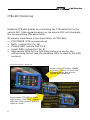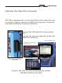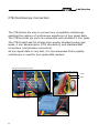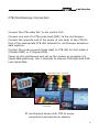
1
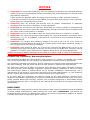
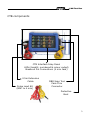
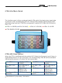
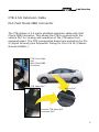
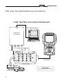
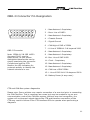
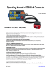
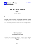
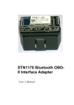
CAN Test Box Quick Start User Guide CAN Test Box NOTICE 1. Important: As active LED signals may have the potential to interfere with CAN data package signals we do not recommend the CTB be connected to late model CAN protocol vehicles under the following conditions: i. With a scan tool attached whilst driving the vehicle during or under road test conditions. ii. CTB left connected to the vehicle DLC OBDII connector while road testing or left connected to the vehicle for extended periods of time. 2. Important: Only use external test devices such as probes, oscilloscopes or diagnostic equipment with more than 1 megaohm of input impedance. 3. Important: Do not connect the CTB when performing any vehicle re-flash or reprogramming procedures with scan tool or pass-thru programming devices connected. Failure to observe this can cause control module failure or damage. 4. Important: Do not use the CTB to power any external test devices in excess of 1.2 amps. 5. Important: Use caution at all times when probing the 16 pin DLC breakout connection panel. Bridging pins, e.g. pin 16 (POWER), to any other pin could result in serious vehicle electrical or computer damage. 6. Important: The working and operating voltage of the CTB is 12 V to 32 V DC. Under no circumstances should the CTB be used on any vehicle which has a higher operating voltage or the CTB unit will be permanently damaged. 7. Important: Care should be taken not to drop the CTB onto the OBD female end or to use excessive force when connecting a scan tool, as the CTB 16 pin female DLC connector may be pushed in or broken. This is deemed to be operator abuse and is not a warrantable item. Failure to observe these warnings may result in vehicle, CTB or scan tool damage or incorrect test results. Product Use Limitations, Warranty Disclaimer Pico Technology supplies the CAN Test Box (CTB) product for a number of intended uses. Please refer to the product label for the intended use statements for specific product applications. Pico Technology warrants upon delivery, and for a period of 12 months unless otherwise stated from the date of delivery, that the Goods will be free from defects in material and workmanship. Pico Technology shall not be liable for a breach of the warranty if the defect has been caused by fair wear and tear, wilful damage, negligence, abnormal working conditions or failure to follow Pico Technology’s spoken or written advice on the storage, installation, commissioning, use or maintenance of the Goods or (if no advice has been given) good trade practice; or if the Customer alters or repairs such Goods without the written consent of Pico Technology. In no event shall Pico Technology be liable for claims for any other damages, whether direct, incidental, foreseeable, consequential, or special (including but not limited to loss of use, revenue or profit), whether based upon warranty, contract, tort (including negligence) or strict liability arising in connection with the sale or the failure of the CAN Test Box to perform in accordance with stated specifications. DISCLAIMER Please note when using the CTB as a scan tool extension lead, protocol interference may be possible on some vehicle manufacturers when entering into some ECU’s. IMPORTANT: CTB should not be attached when reading or clearing fault codes or during any programming, adaption or special functions when used in conjunction with a scan tool. CAN Test Box CTB components CTB Interface Inlay Panel LEDs (backlit, numbered & colour coded) Breakout Pin Connections (4 mm Jack) 2.5m Extension Cable Probe Lead Kit (BNC to 4 mm) OBD Scan Tool Pass-Thru Connector Protective Boot 3 CAN Test Box CTB Interface Panel The interface panel utilises numbered backlit LEDs which illuminate when signal data is present on the corresponding LED line. Pulsing LEDs indicate signals being pulled alternately high and low. CTB LEDs correspond to vehicle DLC (Data Link Connector) Pins 1-16. LEDs 1-4 GREEN, LEDs 5-8 BLUE, LEDs 9-12 YELLOW, LEDs 13-16 RED CTB POWER LED RED CTB LED Description When the CTB is interfaced with the vehicle DLC (Data Link Connector) and if there is signal data present on a pin of the DLC, the corresponding CTB LED will be activated indicating the presence of vehicle DLC pin signal data. 1: 485A * 5: Signal GND (SIGNAL) 2: Bus+ Line 6: CAN High of J1850 SAE J2284 3: future upgrade 7: K Line of ISO9141-2 & keyword 2000 4: Chassis GND 8: future upgrade (GROUND) * Manufacturer’s proprietary information 4 9: 485B * 10: Bus– Line J1850 11: Clock 12: future upgrade 13: future upgrade 14: CAN Low of SAE J2284 15: L Line of ISO9141-2 & keyword 2000 16: Batt+ (Voltage Supply) CAN Test Box CTB 2.5m Extension Cable DLC Fast Check OBD Connector The CTB utilises a 2.5 metre shielded extension cable with Fast Check ODB Connector. This allows the CTB to connect with the vehicle DLC for viewing and operation of the CTB away from enclosed areas. The CTB incorporates diode fuse protection for Pin 5 (Signal Ground) plus Polyswitch Fusing for Pins 4 & 16 (Chassis Ground & Batt+). CTB 2.5m Cable and Fast Check OBD Connector CTB Cable DLC Vehicle DLC Connect CTB cable DLC to vehicle DLC. 5 CAN Test Box CTB LED Monitoring Establish CTB LED display by connecting the CTB cable DLC to the vehicle DLC. Data signals present on the vehicle DLC will illuminate the corresponding CTB panel LEDs. Of primary importance is the illumination of CTB LEDs: • • • • • CTB POWER (CTB is powered up) Batt+ (vehicle DLC Pin 16) Chassis GND (vehicle DLC Pin 4) Signal GND (vehicle DLC Pin 5) Appropriate LEDs for the CAN data protocol in use for the vehicle being tested (use the pulsating LEDs to identify the CAN protocol). Test Vehicle Example - Mazda CX7 5 Image shows CTB LEDs; POWER, 4 (green), 5 (blue) 16 (red) ‘ON’ indicating power and ground circuits are operational Signal GND POWER 4 Chassis GND 16 Batt+ Image shows CTB LED’s 6 (CAN High) and 14 (CAN Low) - system uses SAE J2284 protocol and is in ‘wake up’ mode 6 CAN Test Box CTB Scan Tool Pass-Thru Connector The CTB is equipped with a 16 pin Pass-Thru which allows the user to connect a scanner (generic or OEM) for the purpose of systems scan data monitoring or systems activation. Connect the CTB cable DLC to the vehicle DLC. Connect the scan tool cable DLC to the CTB Pass-Thru Connector. Scan Tool Data Display CTB Pass-Thru to Scan Tool Cable Connection CTB 16 Pin Pass-Thru Connector CTB LED Display Connect CTB, Scan Tool and simultaneously monitor CTB LEDs and Scan Tool Data 7 CAN Test Box CTB Oscilloscope Connection The CTB allows the user to connect any compatible oscilloscope enabling the capture of oscilloscope waveforms of bus signal data. The CTB terminal pin ports are accessible with standard 4 mm jacks. The CTB Probe/Lead Kit utilises high-quality shielded probes and leads, 4 mm banana jacks (CTB connection) and standard BNC connectors (oscilloscope connection). As bus signal data is very fast, it is recommended that a quality oscilloscope is used for bus signal data capture. CTB 4 mm Terminal Pin Ports CTB Probe/Lead Kit 4 mm BNC CTB 4 mm Pin Port PC Oscilloscope (BNC Connectors) 8 CAN Test Box CTB Oscilloscope Connection Connect the CTB cable DLC to the vehicle DLC. Connect one end of a CTB probe lead (BNC) to the oscilloscope. Connect the opposite end of the probe (4 mm jack) to the CTB Pin Port of the appropriate CTB LED selected for oscilloscope waveform data capture. Connect the probe ground (black lead) to CTB LED Pin Port either 4 (Chassis GND) or 5 (Signal GND). Power up the oscilloscope and set up the system as necessary for signal data gathering. Use 2 channels to observe CAN High and CAN Low signal data. CTB Probe (4 mm) Connection CTB Connected to Vehicle DLC CTB Probe Lead (BNC) Scope Connection Oscilloscope Waveform Capture PC oscilloscope shown with CTB-to-scope connections and waveform capture 9 CAN Test Box CTB, Scan Tool and Oscilloscope Connections CAN Test Box Connection Schematic PC USB Connection USB Automotive Oscilloscope B A D C CAN Low Signal Ground CAN High Ground 1 5 9 13 2 6 10 14 3 7 11 15 4 8 12 16 Scan Tool Connection CAN Test Box WARNING! Vehicle DLC 10 Observe workshop safety practices CAN Test Box OBD-II Connector Pin Designation 1 2 3 4 9 10 11 12 5 6 7 8 13 14 15 16 1 - Manufacturer’s Proprietary 2 - Bus+ Line of J1850 3 - Manufacturer’s Proprietary 4 - Chassis Ground 5 - Signal Ground 6 - CAN High of SAE of J2284 OBD II Connector Note: ISO9141-2 & ISO 14230 (keyword 2000) use the same pinout, so you cannot distinguish between the two by simply examining the connector. Connect and use the CTB. Monitor the LED indicators for protocols activity to identify the network structure in use. 7 - K Line of ISO9141-2 & keyword 2000 8 - Manufacturer’s Proprietary 9 - Manufacturer’s Proprietary 10- Bus- Line of SAE J1850 11- Clock - Proprietary 12- Manufacturer’s Proprietary 13- Manufacturer’s Proprietary 14- CAN Low of SAE J2284 15- L Line of ISO 9141-2 & keyword 2000 16- Battery Power (4 amp max.) CTB and CAN-Bus system diagnostics Please note: Some vehicles may require connection of a scan tool prior to connecting the CAN Test Box. This is necessary as a scan tool may be needed to log on as a communication node of the CAN-Bus system. Without scan tool recognition, the system will not transmit signal data to the CTB and therefore connection of the CTB may result in failure of the CTB interface LEDs to operate when performing a diagnosis. 11 May 2013 DO148-3