1
SeamCAD 1.x: User’s Guide
Lam-Son Lê, Alain Wegmann
Laboratory of Systemic Modeling
School of Computer and Communication Sciences
École Polytechnique Fédérale de Lausanne (EPFL)
CH-1015 Lausanne, Switzerland
{LamSon.Le, Alain.Wegmann}@epfl.ch
http://lamswww.epfl.ch/
Technical Report No. IC/2004/98
Abstract: The enterprise architecture’s goal is to integrate business resources and IT resources in order
to improve an enterprise’s competitiveness. Our goal is the development of an object-oriented enterprise
architecture method, called “SEAM”. As part of SEAM, we have developed the CAD tool “SeamCAD”.
SeamCAD enables the modeling of hierarchical systems (spanning from business down to IT) at different
levels of detail (e.g. from large business transaction to detailed interactions). This document is the user’s
guide of SeamCAD 1.x. It first gives an overview of the foundations of our method and then illustrates the
functionalities of the tool.
- Page 1 -
Table of Contents
1
2
Introduction ........................................................................................................................ 3
SEAM Overview ................................................................................................................ 3
2.1
Method Overview....................................................................................................... 3
2.2
Tool Overview............................................................................................................ 6
2.3
Example...................................................................................................................... 7
2.4
Legal Considerations................................................................................................ 11
3
Installing and starting SeamCAD..................................................................................... 12
3.1
Downloading the Client ........................................................................................... 12
3.2
Login ........................................................................................................................ 12
3.3
Using the Main Window .......................................................................................... 13
3.4
Filling User Information........................................................................................... 13
3.5
Submitting a Problem............................................................................................... 14
3.6
Getting Info with the Output Window ..................................................................... 14
3.7
Quick Meta-model.................................................................................................... 15
3.8
User’s Guide and Tips of the Day............................................................................ 15
4
Navigating an Existing Model.......................................................................................... 16
4.1
Opening an Existing Model...................................................................................... 16
4.2
Working with Modeling Windows........................................................................... 16
4.3
Simplifying Model Representation .......................................................................... 18
5
Building a New Model ..................................................................................................... 18
5.1
Creating a New Model ............................................................................................. 19
5.2
Inserting a Holon...................................................................................................... 19
5.3
Inserting a Joint Action ............................................................................................ 20
5.4
Inserting an Information Object ............................................................................... 20
5.5
Inserting a Localized Action .................................................................................... 20
5.6
Relating Model Elements ......................................................................................... 20
5.7
Inserting a Note ........................................................................................................ 22
5.8
Modify an Existing Model Element ......................................................................... 22
5.9
Delete an Existing Model Element........................................................................... 23
5.10 Saving the Model ..................................................................................................... 23
6
Miscellaneous Functionalities .......................................................................................... 24
6.1
Export the Working Model to an XML Document .................................................. 24
6.2
Export the Modeling Diagram to a GIF Picture....................................................... 24
6.3
Picture for Holon...................................................................................................... 25
7
Tool Architecture ............................................................................................................. 25
Appendix A: Web Prototypes .................................................................................................. 26
Prototype 1 ........................................................................................................................... 26
Prototype 2 ........................................................................................................................... 27
Appendix B: References........................................................................................................... 29
- Page 2 -
1 Introduction
For our enterprise architecture methodology, we have developed a CAD1 tool called SeamCAD. Our
enterprise architecture method is called SEAM (for “seamless” integration between business and IT, or for
“Systemic Enterprise Architecture Methodology”) [1]. The main originality of our tool is its capability to
manage hierarchical models. SeamCAD is a web-based application implemented in Java.
Section 2 gives an overview of our method, of the tool interface and an example of a hierarchical model.
This section helps the readers in getting acquainted with our method and with the tool. Section 3 presents how to
install the tool and how to start it. Section 4 presents how to navigate a model. Section 5 explains how to create a
new model. Section 6 presents miscellaneous functions. The tool architecture is briefly described in Section 7.
An appendix presents two prototypes that were developed before the first functional version of SeamCAD.
This appendix is relevant for readers who want to learn about the research and development history of
SeamCAD.
2 SEAM Overview
This section gives an overview of SEAM. Subsection 2.1 gives an overview of the foundation of the
method, especially of its modeling language, and points out some related approaches. Subsection 2.2 briefly
presents the goal of the tool and then defines the tool-related terms that users should be acquainted before
actually using SeamCAD. Subsection 2.3 relates the SEAM concepts given in 2.1 with the tool concepts
presented in Subsection 2.2. This is done by presenting a SEAM model of an on-line bookstore. Section 2.4
presents the legal considerations about the tool usage.
2.1 Method Overview
The enterprise architecture’s goal is to integrate business resources and IT resources in order to improve an
enterprise’s competitiveness. Enterprise architecture (EA) deals with hierarchical systems that typically span
from business entities (market, company, department…) down to IT components (e.g. applications, applets,
servlets, bean, COM…). Our goal is the development of an object-oriented enterprise architecture method, called
Systemic Enterprise Architecture Methodology (SEAM) [1]. This method is based on the Miller concept of level
[2], on the Reference-Model of Open Distributed Processing (RM-ODP) [3] and on a few philosophical
principles. This section presents these bases and some considerations related to the SEAM notation.
Miller’s Living System Theory:
James Greer Miller made a thorough cross-discipline analysis and synthesis of the functions and behavior of
living systems to develop a theory called “General Theory of Living Systems” or “Living Systems Theory”
(LST) [2]. The main goal of LST is to unify all scientific disciplines that study and model livings systems. In
particular, LST integrates structural and behavioral sciences but still keeps some of the specificities of the
individual disciplines. One of the most important concepts is that of level. According to Miller “…the universe
contains a hierarchy of systems, each more advanced or ‘higher’ level made of systems of the lower levels”. He
identifies seven distinct levels for living systems: cells (free-living cells and aggregated cells), organs, organisms
(such as humans…), group (such as families, workgroups…), organization (such as commercial companies…),
society (such as countries) and supra-national systems (such as inter-governmental organizations …). This level
distinction is tightly linked to people’s experience in perceiving and studying the world of livings systems.
Depending on the goal of the modeler, it is possible to have more or less levels.
To be able to fully model enterprises, the model should not be limited to the IT and software-intensive
systems but should also represent the business-related systems. To be able to distinguish between these different
aspects, SEAM has a concept of organization level (which is similar to Miller’s level). These organizational
levels exist within an organizational level hierarchy.
1
We call it a CAD (Computer Aided Design) tool as opposed to CASE (Computer Aided Software Engineering) tool because it deals with
not only software modeling but also business modeling.
- Page 3 -
Reference Model of Open Distributed Processing:
Within the organization levels, we use RM-ODP to represent what is perceived as relevant for the project.
RM-ODP is a standard that defines the concepts necessary to model “distributed information processing services
to be realized in an environment of heterogeneous IT resources” [3]. RM-ODP also proves to be suitable for
general modeling [4].
According to RM-ODP part 2 (i.e. the foundations part of RM-ODP), an entity is any concrete or abstract
thing of interest in the universe of discourse. An entity can be considered as atomic or as non-atomic (i.e.
composed of components of the same kind). An entity is represented in the model as a model element. So, a
model element can be seen as whole or as composite. A system may be referred to as an entity. We define a
system as a set of entities that have relationships between them; that are perceived as relatively, and that create,
for an observer, emergent properties. A component of a system is itself a system, so it is called a sub-system.
The model element that corresponds to a system is an object. An object can be seen as whole (i.e. this
corresponds to the external view of the object, also called model-based specification [5]) or as composite (i.e.
this corresponds to the internal view, or implementation, of the object). Other kinds of entities can be modeled as
action and state. Actions and states can also be seen as whole or as composite. An action or a state seen as
composite can be broken down into component actions or states. These component actions or states can be
further broken down into smaller component actions or states. This hierarchy of actions and states corresponds to
the detail level hierarchy. The detail level hierarchy includes detail levels. This hierarchy is orthogonal to the
organizational level hierarchy defined in the previous section (in which an object is broken down into its
component objects). In each organizational level, multiple detail levels can exist.
According to RM-ODP part 3 (i.e. the architecture part of RM-ODP), a system specification has five
viewpoints: enterprise, information (made of information objects), computational (made of computational
objects), engineering and technology viewpoint. In RM-ODP, these five viewpoints describe one IT system. The
information viewpoint (describing the IT system specification) and the computational viewpoint (describing the
IT system logical components) are somewhat central. The enterprise viewpoint summarizes the business issues.
The engineering and technology viewpoints summarize the IT implementation issues. In SEAM, as our goal is to
model in systematic manner systems that spans from business down to IT, we distinguish between the business,
the IT system and the IT system components by having different organization levels. However, in each level, the
relevant systems can be described by their information and computational viewpoints. So, in SEAM, we model
organization levels made of computational objects (i.e. an object that represents a system). The computational
objects can be specified by either an information viewpoint (of the computational object seen as a whole) or by a
computational viewpoint (of the computational object seen as a composite).
A computational object as a whole is represented by information objects (IO) and localized actions (LA).
The information objects are like attributes and represent the states of the computational objects. The localized
actions represent the computational object’s responsibility. The information objects represents either the fact that
a localized action executes (information objects called transactions) or parameters exchanged with the
environment (information objects called parameters) or elements of “knowledge” (information objects called
concepts). The “knowledge” of the computational object is about itself or about other computational objects
belonging to the same organizational level.
A computational object as composite is represented as component computational objects and actions
happening between them that we call joint actions (JA).
Note that as RM-ODP part 2 just defines the term action, we have to define the localized actions and the joint
actions. The names of these actions are taken from Catalysis [6].
Philosophical Principles:
SEAM is based on a few important philosophical principles that explain how we perceive reality [7]. The
main two are: constructivism and teleology.
Constructivism is the principle stating that “knowledge is the product out of social practices and institutions
or of the interactions and negotiations between relevant social groups” [8]. Concretely this principle explains
why people hierarchical levels and what is perceived to be in each level. This is the result of the practices taught
and used in all disciplines involved in an enterprise architecture project.
Teleology is one way people give meanings to the behavior of the systems they observe. Teleology is defined
as “the philosophical doctrine that all of nature, or at least intentional agents, are goal-directed or functionally
- Page 4 -
organized” [8]. So, according to the teleological principle, the modelers need to be able to assign goals to the
systems they model. In SEAM, we consider that the computational objects represent entities that are goaldirected in the sense that they have some goals when collaborating one with another (or that their designers have
goals to be fulfilled by the entities). We consider two kinds of goals: detail- level related goals and
organizational-level related goals.
For example, the modeler can decide to make the information viewpoint of the computational object. The
information viewpoint shows information objects modified by localized actions, which are initially represented
as whole. The modeler can decide to make a more detailed information viewpoint with a localized action as
composite (made of many smaller ones). These two information viewpoints correspond to two detail levels. The
first one corresponds to the specification of the goal and the second one to the specification of the means. This
corresponds to goals/means relationship along the detail level.
The modeler can also decide to make the computational viewpoint of the computational object. This
viewpoint shows the component computational objects that make the computational object of interest. This is
another of goals/means relationship that we call goals/means relationship along the organizational level. Some
people call this a specification/implementation relationship. We do not use these terms because they contain an
implicit reference to a development process. In fact, the information and the computational viewpoints are
complement to each other. Both viewpoints exist independently of any development process.
Terminology and Notation:
Our core business is the hierarchical modeling of systems. Our definition of system is generic and can be
applied to characterize any systems such as markets, business systems, companies, IT systems, etc… Our
experience showed that people gets easily confused with the term system when used in a generic manner (as it is
difficult to ignore the specific instance of system that they know). For this reason, SEAM uses the term holon
instead of system. We term holon was defined by Kostler in [9] and its use is recommended by Checkland [10].
The term holon is the elementary unit of the fundamental holistic element. It is the combination of “hol” from
holisitic and ends with “on” as electron, proton, and neutron.
As explained above, an entity representing what we consider as a generic system is represented in the model
as a computational object. For sake of simplicity, we use the term holon for the computational objects. To be
rigorous, we should have called the computational objects model of holon. The holon is a system perceived in the
reality and the model of a holon is its representation of in the model. To be practical, we call all of them holon.
Bottom line, in SEAM, we have organizational levels in which holons are represented either as whole or as
composite. A holon represented as whole is synonymous to the information viewpoint of a computational object.
A holon represented as a composite is a synonymous to the computational viewpoint of a computational object.
Our tool allows changing the shape of the representation of the holons. This is useful as it allows using a
graphical element that acts as a reminder of organizational level shown. For example, holons in the businessrelated levels are shown as a Porter’s arrow [11]. In the IT related levels, a system is represents by a UML subsystem. Both graphical elements are considered the same for the CAD tool, only the appearance differs. Our tool
also allows placing pictures or drawings next to the holon. This is useful to make the model more concrete.
The notation we used is inspired by Unified Modeling Language (UML) [12]. However, we use our own
meta-model (which is the formal definition of the RM-ODP concepts to which we added few concepts such as
organization level, detail level, localized action, joint action…). The relation between our meta-model and the
UML meta-model is explained in [13]. The main graphical elements are
- Holon represented either as a UML sub-system, or as a Porter’s arrow or as a stickman;
- Information object: rectangle like UML class (without attributes or methods);
- Joint action: ellipse as a UML collaboration
- Localized action: rounded rectangle as a UML action state (in activity diagrams)
Comparable Approaches:
Our method can be compared to other object-oriented methods that address hierarchical modeling, such as:
Catalysis [6], Kobra [14], SysEng [15] and OPM [16] [17]. For a comparative analysis, please refer to [18].
Catalysis did inspire SEAM. The main difference lies in the foundations of SEAM (explained above) that do not
exist in Catalysis. Thanks to these foundations it was possible to build a CAD tool that deals in a systematic way
with a potentially unlimited number of the organizational levels. It was also possible to understand how to
- Page 5 -
represent Catalysis models in UML. Kobra and SysEng are based on UML. As the meta-model of our notation is
simpler and more systematic than the original UML meta-model, we can provide a simpler and more systematic
way to represent hierarchical systems than Kobra and SysEng. In addition, these methods use traditional UML
tools and these tools have problems to deal with the full generality of hierarchical system modeling (and have
problems such as contextual naming). Last, OPM is quite close to SEAM. It illustrates well the principle of
hierarchical system modeling. Unfortunately, OPM has few shortcomings that SEAM does not have (such as, for
example, the difficulty to deal with the modeling of multiple systems in parallel). However, OPM is the only
method - other than SEAM - that has a CAD tool that can truly represent hierarchical systems. This CAD tool
uses a notation which is quite different from UML.
The main difference between SEAM and the Zachman framework [19], popular in EA, is that SEAM is
object-oriented and Zachman is not object-oriented. Our choice of an object-oriented approach is justified by our
attempt to have a consistent modeling paradigm between IT and business organization levels. In software
engineering, objects are widely used and UML has made a significant impact. All the concepts existing in
Zachman can be found in SEAM. Thanks to its foundations, SEAM can make explicit the relations between
these concepts. This is a very important advantage as it makes SEAM simpler to use in practice than the
Zachman framework. It is conceivable to generate Zachman models from a SEAM model.
2.2 Tool Overview
This section presents our goals for the tool as well as the main elements of the tool user interface.
Our goals:
Our experience in hierarchical modeling of systems shows that existing CAD tools have important
shortcomings. The presentation of these shortcomings is out of the scope of this paper. However, we can still
mention the main and most frequent one. It is the CAD tool difficulty to manage contextual names (i.e. when a
same name can appear in multiple contexts). SeamCAD does address this issue (by keeping trace in which
holons the names are defined).
To be able to illustrate, teach, and practically apply hierarchical modeling, we were forced to develop our
own CAD tool. This manual describes our first functional version (more on the tool history in the Appendix).
We have three applications for SeamCAD:
- SeamCAD as a research tool: the tool allows our group to test the SEAM foundations and to
develop a graphical interface that lets users cope with the complexity of hierarchical models. The
tool can also generate XML code that can be imported in other tools such as model checkers or
simulators. This is useful to validate how the SEAM models can be related to other modeling
techniques (such as formal languages, like AsmL [20], or as system dynamic models [21]).
- SeamCAD as a teaching tool: the tool allows teaching students and professionals about abstractions
(e.g. organization level hierarchy or detail level hierarchy). It allows illustrating the foundations
underlying any modeling languages (such as UML). Even if UML is used in a project, the
knowledge of SEAM is useful to understand the fundamental principles underlying modeling. By
its capability to export models to other tools (such as model checkers and simulators), SeamCAD
can be used to illustrate how the different modeling techniques can be related to each other.
- SeamCAD as a possible “commercial” enterprise architecture tool: the tool can be used in real
enterprise-wide projects. It is used currently for small projects. Its main use is not for modeling the
entire project but rather for modeling some key aspects of the projects.
Main user interface elements:
The tool works as a client-server application. The client can be downloaded and execute as a Java
application, which has the Java Swing (TM) user-interface. The client communicates with the server via a web
protocol. All models are centrally managed by the server.
The modeler should be familiar with the following terminologies before practicing the tool:
- Modeler: the user of the tool. She is called the modeler because she uses the tool to model something in
reality.
- Page 6 -
-
-
-
-
-
-
-
-
Model: a model (sometimes called a project) created by a modeler. A model consists of model
elements. For example, a model about the car may consist of elements such as wheel, engine, color,
brand name, start, brake, accelerate… Refer to Subsection 2.1 for the definition of different kinds of
model elements.
Tool administrator: person in charge of managing the tool and the models. The administrator creates
user accounts, grants user rights, makes backups and can delete/rename models.
The tool has windows:
Main window: this window, which has menu and toolbar, appears after the modeler successfully
logged in. It displays the modeler’s information as well as the hierarchy of the model being
manipulated. This window is unique (only one instance of the window exists in a modeling session).
The menu and the toolbar of the main window allow the modeler to open/export/save her models and of
course to logout/exit to end the current session. Very important: the modeling windows can be opened
from the main window.
Modeling window: a window that display the hierarchy of the model being manipulated on the left and
the visual model on the right. This window also has some menu and toolbar to help the modeler
manipulate her model and her diagram. Many modeling windows can coexist in one session. This
allows showing different views of a same model (and to see how changes percolate from one part of the
model to another part of the model).
Output window: a text-based window displaying the messages issued by the tool for typical actions
such as opening, saving, creating, deleting… These messages are useful for the modeler especially in
case of problem.
The windows have panels:
Navigation panel: a tree view displaying the hierarchy of the model opened. The tree is made of tree
nodes that represent holons and joint actions. The root node represents the name of the model. The
unique child node of that root node represents the “top” holon of the model. The child nodes of this
node represent the component holons of the main holon plus the joint action they participate in. This
representation is carried out until the “deepest” holons and joint actions are reached. The navigation
panel is painted on the left of the main window and in all modeling windows. All navigation panels
represent the same model – the model being opened. In the modeling windows, the modeler can interact
with the navigation panel to view the model in the way she wants on the graphical panel.
Property panel: a panel consisting of text fields that allow the modeler to edit the selected model
element in the diagram in terms of name, description, stereotype… Every modeling window has a
property panel at the bottom-left corner. Note that the main window has also a property panel that
enables modification of the model related information.
Graphical panel: a panel visible only in the modeling window and that shows the model in a graphical
way.
The windows have menus:
- Menu bar: each window has a menu bar in the upper part of the window. Most commands can be
reached by the menu bar and by the contextual pop-up menus.
- Contextual popup menu: in the graphical panel and navigation panel, each model elements has a
popup menu that allows the modeler to interact with the selected model element.
2.3 Example
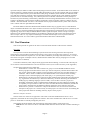
This section illustrates how to work with SeamCAD 1.x through an example about a bookstore company
whose management decides to sell books via Internet. In this example, an enterprise model is developed. An
enterprise model is a hierarchical model that represents a company, its market and its internal organization. The
bookstore’s enterprise model is made of levels. Figure 1 shows an informal representation of what is in the
enterprise model.
- Page 7 -
BookCoMarket
Market level
Business system level
Company level
Department level
Technology level
BookCoBis
ShipCo
PurchasingDep
OpApp
CustomerBis
BookCo
PubCo
WarehouseDep
Clerk
Additional levels
(not shown)
Figure 1. Hierarchical representation of the systems represented in the enterprise model
The market level represents BookCoMarket composed of the business systems BookCoBis and
CustomerBis. The business system level represents companies or individuals working together to achieve a
commercial goal. In our example, the business system of the on-line book company (BookCoBis) is composed
of the book publisher (PubCo), of the company itself (BookCo), of the shipping company (ShipCo) and of the
bank. The business system of the customer is composed of the end customer, the bank and the shipping company
that delivers the books (not represented in Figure 1). The company level represents the departments operating
inside the companies. More specifically, in this example, BookCo has a purchasing department
(PurchasingDep) that collaborates with the warehouse department (WarehouseDep) for processing the
customers’ orders. The department level represents employees and IT systems. In our example, the purchasing
department consists of a clerk and of an order processing application (OpApp). One of the main goals of the
project is to redesign OpApp to add e-commerce capabilities; but the project also needs to redefine the
responsibilities of the employees and of the departments. Note that it would be possible to have additional levels
for describing the IT system implementation (e.g. server level, component level and programming language class
level).
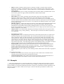
Table 1 lists screenshots of SeamCAD in modeling the online bookstore throughout 5 organizational levels
described above. Note that each row in Table 1 has a diagram corresponding to a specific organizational level. In
each level, the selected holon (BookCoBis, BookCo, PurchasingDep, OrderProcessing and
SearchServlet) becomes the context holon in the subsequent level. The main joint action in each level (except
the market level) is attached a note indicating that it is the implementation of the main localized action of the
selected holon in the previous organizational level. The last row shows the main window that manages all 5
modeling windows opened.
- Page 8 -
Market level
Table 1. Modeling windows and the main window in SeamCAD for the model of the online bookstore
Business system level
In the market level, BookCoBis, CustomerBis and some other business systems (OtherBis)
collaborate through a joint action called serve, which is broken into two smaller actions named procure
and pay. Action procure represents that fact that BookCoBis processes the orders issued by
CustomerBis. BookCoBis collaborates with OtherBis to make payment (action pay). BookCoBis has
two sub-transactions (ProcureTxn and PayTxn) and two component localized actions (Procure and
Pay) corresponding to the 2 joint actions it participates in.
In business system level, joint action mfg_sale represents the collaboration between BookCo, PubCo and
ShipCo.
- Page 9 -
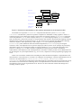
Company level
Department level
In the company level, the main joint action market between the two departments are broken down into
select (identifying the demanded books), pack (preparing the demanded books for shipping) and
order (doing the paper-work for the orders coming from the customers). In the diagram of the company
level, PurchasingDep has sub-transactions and component localized actions for joint action select and
order. WarehouseDep has sub-transactions and component localized actions for joint action pack and
order.
In the department level, the clerk operates the application OpApp, which searches for the demanded books
in the inventory and processes the orders coming from the customer.
- Page 10 -
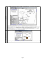
Technology level
Main window
In the technology level, OpApp consists of the servlet SearchServlet responsible for searching books in
the database and the Java Bean OrderPrinterClass responsible for printing the orders.
In the main window, the modeler can open a new modeling window and switch to or close existing
modeling windows. The main window also reminds the modeler of the hierarchy of the model being
opened.
2.4 Legal Considerations
SeamCAD copyright © 2004 Laboratory of Systemic Modeling (LAMS), School of Computer and Communication Sciences,
École Polytechnique Fédérale de Lausanne (EPFL). All Rights Reserved. Permission to use, copy, modify and distribute this
software and its documentation without a written agreement is hereby granted, provided that the above copyright notice and
this paragraph appear in all copies. LAMS does not warrant that the operation of SeamCAD will be uninterrupted or errorfree. The end-user should understand that the program was developed initially for research purpose and is encouraged to
leave a feedback on it (see Subsection 3.5 on how to report a problem).
- Page 11 -
3 Installing and starting SeamCAD
SeamCAD is packaged as a JAR file. The modeler just downloads it and then starts… It is recommended to
use the tool on a large display screen with a resolution of at least 1280 x 1024. It would be great if the computer
on which SeamCAD is executed has two displays (for instance, an external monitor can be connected to a laptop
and recognized as an extended display in Windows 2000/XP).
3.1 Downloading the Client
The client of is a Java application which can be downloaded and executed at any Java2 (TM)–enabled
platform.
If you are not sure about which Java Virtual Machine (JVM) is in your machine, you should:
- Open the command line (in MS Windows (TM), use the “Start” menu, select “Run…” and then
type “cmd” as the program to run, press “OK” to open the command line window).
- Type “java –version” to check its version.
Note: running “java –version” should yield “Java (TM) 2 Runtime Environment”. Otherwise you need
to install the new JVM (http://www.java.com)
To run the application, you should:
- Download your favorite version (probably the newest one) of the client into one of your local
directory from SeamCAD’s homepage http://seamcad.epfl.ch.
- Open the command line (in MS Windows (TM), use the “Start” menu, select “Run…” and then
type “cmd” as the program to run, press “OK” to open the command line window).
- Change to the directory where you have downloaded the client (using the command “cd” with that
directory as the parameter).
- Type “java –jar SeamCAD.jar” to start the client
Note: under MS Windows (TM), if JVM is correctly installed, it is enough to download the client and to
double click on the jar file.
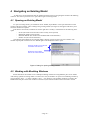
3.2 Login
Figure 2 shows the login dialog that you get when starting SeamCAD. If you are registered user, type your
username and password and then press “Login”. If you are not a registered user, you can log with the “guest”
username and the “guest” password. As guest, you are only allowed to view the model “Example”. Instead of
typing “guest”, you can also press the button having a human icon. If you wish to become a registered user, you
can send an email to the administrator of SeamCAD (listed in SeamCAD’s homepage, see Subsection 3.1) to get
the username and password.
Note: it is possible to choose the favorite Look and Feel before logging in.
Error messages will
be displayed here
Uncheck this box to
prevent the tips being
launched next login
The Look And Feel
of the windows can
be chosen from this
combo box
Figure 2. Login dialog
An error message is issued in the following cases
- Page 12 -
-
There is no account with the specified username
The password is wrongly typed
Somebody has logged in with the username you typed
Your machine is not connected
The server of SeamCAD is down
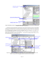
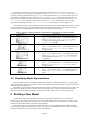
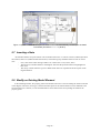
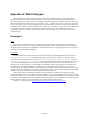
3.3 Using the Main Window
After having successfully logged in, the modeler gets the main window as shown in Figure 3 (In fact, tips of
the day may be launched for the first login, see Subsection 3.8 for more details). The main window has 4 panes
that are divided by one vertical splitter and two horizontal splitters. The splitters can be moved to resize the
panes. The upper-left pane is used for displaying the hierarchy of the model opened (see Subsection 4.1). The
lower-left pane help the modeler manage modeling windows (see Subsection 4.2). The upper-right pane shows
the information of the modeler and the model opened (see Subsection 3.4). The lower-right pane presents the
status of the submitted problems (see Subsection 3.5).
Figure 3. Main window
For normal use, we recommend reducing the width of the right panels to save screen space. The right part of
the main window is only rarely used.
3.4 Filling User Information
Information about SeamCAD’s users is stored on the server. This information helps the administrator
contact the users in case of problems. The user (only when logged in a non anonymous way) should fill in the
text fields in the upper-right pane of the main window and then press button “Save user info” to store their
contact information.
- Page 13 -
3.5 Submitting a Problem
The registered users are encouraged to submit problems they found. SeamCAD has a function to keep
track of all problems submitted as a means for the interaction between the user and the developer. Each problem
has 4 possible statuses: DISCUSSED, IN-PROGRESS, DEBUGGING and DONE. A problem initially has status
DISCUSSED when it is submitted. It is then discussed by the developers of SeamCAD on whether to be solved
or not. It is changed to IN-PROGRESS if the developers decide to solve it. When it is completely finished, it is
marked as DONE. Sometimes it is marked as DEBUGGING if the developers are debugging it. Only the
administrator can update the problem status. All problems are presented in the lower-right pane of the main
window so that the modelers can learn about the development of the tool.
The users should notice that it is important to carefully scan through the existing problems in the lowerright pane of the main window to avoid submitting a new problem that is the same as or similar to an existing
one. A problem is either a bug or an essential functionality that is missing in the current version of the tool.
The following steps should be taken in order to submit a problem
- Identify a bug or an essential functionality that is missing in the current version
- Read through the existing problems in the lower-right pane of the main window to see if there has
already been a problem with similar or the same description.
- In the main window, follow menu “Help | Submit” a problem to open a dialog
- Enter the name of the problem, the description (as much precise as possible) and adjust the priority
of the problem (see Figure 4).
- If necessary, attach an image (like a screenshot made by pressing “PrtSrc” under MS Windows
(TM) and copied into an image processing application. To upload the image, press the button
“Click here to set an image” in the dialog (see Figure 4).
- Press “OK”
Figure 4. Dialog for submitting a problem
At the beginning of each modeling session (see Subsection 3.2), SeamCAD counts the problems that have
been completely solved to be able to inform the modeler if the newer version is available for downloading.
3.6 Getting Info with the Output Window
If the modeler does not fully understand the SEAM modeling language, she sometimes finds that the tool
behaves in a strange manner. It is essential to look at the Output Window to see what happen (see Figure 5). The
Output Window is shown immediately after her login. It reports activities such as creating, deleting model
elements. The modeler can hide it either by manually closing it or by unchecking menu item “Window | Output
window” of the main window. Once hidden, it can be shown by checking that menu item again.
Figure 5. Output Window typically reports logging in, creating and deleting
- Page 14 -
Messages are classified into 3 categories: report (black), warning (pink) and error (red). Note that error
messages always come out with a beep sound!
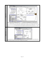
3.7 Quick Meta-model
The modeler can have a quick look at the meta-model of SEAM’s modeling language displayed in a modal
dialog (see Figure 6) by following menu item “Help | Meta-model” of the main window. The terms used in the
meta-model are given in Subsection 2.1.
Figure 6. Dialog displaying the Meta-model
3.8 User’s Guide and Tips of the Day
The modeler can open the electronic copy of this user’s guide in the default browser during her modeling
section by following menu item “Help | User’s Guide” of the main window.
In addition to this user’s guide, “Tips of the day” may give useful answers to most frequently asked
questions about the tool. They may initially be shown when the modeler successfully logs in (see Subsection
3.2). The modeler can launch them anytime again during her modeling session by taking menu item “Help | Tips
of the days” of the main window.
Uncheck this box to
prevent the tips being
launched next login
Click this button to
go to the next tip
Figure 7. Tips of the day can be navigated back and forth
- Page 15 -
4 Navigating an Existing Model
To effectively work with SeamCAD, the modeler should get used to navigating her models with modeling
windows. This section presents how to open and navigate an existing model.
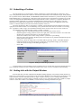
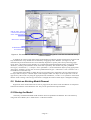
4.1 Opening an Existing Model
To open an existing model, you should use menu “Model | Open Model” or the equivalent button in the
toolbar of the main window. Then a dialog listing existing models (see Figure 8) will appear and allow you to
select the model to be opened.
Note that for each model, a modeler has certain right that is actually a combination of the following basic
rights
- SCAN (the model is listed in the list box but may not be opened)
- READ (the model can be opened)
- READ & WRITE (the model can be modified and saved afterwards)
- EXECUTE (reserved for the future)
The right that the modeler has for selected model is display in blue just above the list of models. The
modeler is prompted if she does not have READ right for the model she wants to open.
Existing models can be filtered
with these radio buttons
Rights that the modeler
has for the selected model
Figure 8. Dialog for opening existing models
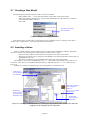
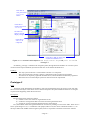
4.2 Working with Modeling Windows
SeamCAD allows the modeler to have multiple modeling windows showing different parts of one model.
After having opened an existing model or created a new one, the modeler can open a new modeling window by
pressing button “New…” or menu “Window | New…” (see Figure 9). All modeling windows are listed in the
middle of the left pane of the main window. From this list, the selected window can be activated or closed.
- Page 16 -
Click here to open a new
modeling window
The selected modeling window in
the list can be activated or closed
Click here to open a new
modeling window (same as menu)
Figure 9.Modeling windows can be opened from the main window. The main window also displays the
hierarchy of the model being opened.
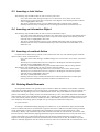
The hierarchy of the opened model is displayed on top-left of the main window (as well as on the modeling
windows). In the modeling window, selecting a node that corresponds to a holon will make it the context holon
in the diagram on the right. This can also be done by right-clicking on the graphical element in the diagram and
then using popup menu “as Context”. For example, selecting tree node BookCo (BIZ as Composite) makes
BookCo as context object consisting of WarehouseDep and PurchasingDep and action market in the
diagram. Right-clicking inside BookCo (but outside WarehouseDep and PurchasingDep) will show a popup
menu. Using popup menu “as Context in New Window…” will open a new modeling window where BookCo is
represented as the context object (see Figure 10).
Click here to make
BookCo as the
context holon
Click here to view
BookCo as whole
Click here to view
BookCo as whole
(an alternative way)
Click here to make
BookCo as the
context holon
(alternate ways)
Figure 10. Holons can be viewed as context object in the current modeling window or in a new
window. They can also be toggled between the whole and the composite.
- Page 17 -
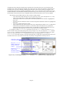
Collapsing or expanding a tree node will make the corresponding holon or joint action as whole or as
composite, respectively. For example, collapsing tree node BookCo (BIZ as Composite) will view BookCo
as whole (containing information object MfgSaleTxn and localized action MfgSale) in the diagram. This can
also be done by using popup menu “as Whole” of BookCo. Once BookCo is viewed as whole, menu item “as
Composite” is available in its popup menu. The corresponding tree node is synchronously renamed to BookCo
(BIZ as Whole) too. Following “as Composite” will view BookCo as composite again. This is actually
equivalent to expanding tree node BookCo (BIZ as Whole) in the hierarchy view (see Figure 10).
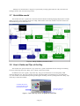
The modeler can open as many modeling widows as she wants. For the model of the online bookstore, from
the main window she can open the 5 modeling windows as demonstrated in Table 2. The modeler can interact
with any of those 5 modeling diagrams. The tool assures the consistency among them.
Table 2. Opening modeling windows in SeamCAD for the model of the online bookstore
Screenshot
Instruction
- From the main window, choose menu item “Window |
New…” or press button “New…” at the bottom-left corner
- Select BookCoMarket (BIZ as Composite) in the
navigation panel and make sure that serve (JA as
Composite) is expanded
Market level
Business system level
-
Company level
Department level
Technology level
From the main window, choose menu item “Window |
New…” or press button “New…” at the bottom-left corner
Select BookCoBis (BIZ as Composite) in the
navigation panel
From the main window, choose menu item “Window |
New…” or press button “New…” at the bottom-left corner
Select BookCo (BIZ as Composite) in the navigation
panel and make sure that market (JA as Composite)
is expanded
From the main window, choose menu item “Window |
New…” or press button “New…” at the bottom-left corner
Select PurchasingDep (IT as Composite) in the
navigation panel
From the main window, choose menu item “Window |
New…” or press button “New…” at the bottom-left corner
Select OpApp (IT as Composite) in the navigation
panel
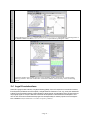
4.3 Simplifying Model Representation
Holons and joint actions can be hidden (and then shown again) to simplify the diagrams. Use popup menu
“Hide” to hide them! The corresponding tree nodes are then grayed. To show them again, right-click on their tree
node and take menu item Show.
The modeler can also hide the main information object and/or localized action of a holon seen as whole. Just
take menu item “Hide info” and/or “Hide action” from it popup menu. To show the main information object
and/or localized action again, take menu item “Show info” and/or “Show action” from the popup menu.
5 Building a New Model
A model can be built up incrementally after it has been opened (see Subsection 4.1) or created (see
Subsection 5.1). The modeler incrementally inserts new model elements into the model she is working on. She
can also modify them. This section presents how to create a new model, how to interactively insert new model
elements into the model and how to modify existing elements.
Note that the toolbar of the modeling window has buttons for creating different kinds of model elements.
Each button has an equivalent menu item in menu “Tool | Insert” of the modeling window. Success or failure in
creating a model element is always reported in the Output Window.
- Page 18 -
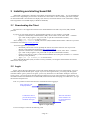
5.1 Creating a New Model
The following steps should be taken in order to create a new model
- Menu “Model | New…” or the equivalent button in the toolbar of the main window
- In the popup dialog (see Figure 11), type the name and description of the model to be created as
well as the name of the root holon.
- Press “OK”
Type the name of the
root holon here
Figure 11.Dialog for creating a new model
Note that the newly created model is not stored in the server database until it is explicitly saved (menu
“Model | Save <model name>” or the equivalent button of the toolbar).
5.2 Inserting a Holon
There are 3 kinds of holon: business (Porter arrow), IT (sub-system) and human (stickman). They differ
only in the notation. The following steps should be taken in order to insert a holon:
- First, click on the button or menu item that corresponds to the object to be created.
- Then drop into a holon seen as composite in the diagram. Note that the potential container object is
highlighted in blue color.
- The newly created holon is given a default name and is ready for being renamed.
For example, to create a new IT department of BookCo, click on the button having a sub-system icon or
menu item “Tool | Insert | IT Computational Object (Holon)” and then drop into BookCo as composite (see
Figure 12).
Note that it is possible to change the type of an existing holon (see Subsection 5.8).
Click here to
start creating a
new IT holon
Drop here to make a
new component
holon of
BookCoBis with the
default name
Rename the
newly created
object here (an
alternative way)
Rename the
newly created
object here
Figure 12. Inserting a holon can be done by clicking the appropriate button or menu item and then
dropping into an existing holon as composite.
- Page 19 -
5.3 Inserting a Joint Action
The following steps should be taken in order to insert a joint action:
- First, click on the button having an eclipse icon or menu item “Tool | Insert | Joint Action”.
- Then drop into a joint action seen as composite in the diagram. Note that the potential container
action is highlighted in blue color.
- The newly created joint action is given a default name and is ready for being renamed.
- Probably relate the newly created joint action to the appropriate holons (see Subsection 5.6)
5.4 Inserting an Information Object
The following steps should be taken in order to insert an information object:
- First, click on the button having a rectangle icon or menu item “Tool | Insert | Information Object”.
- Then drop into an information object seen as composite in the diagram. Note that the potential
container object is highlighted in blue color.
- The newly created information object is given a default name and is ready for being renamed.
- Probably relate the newly created information object to the localized actions that affect it (see
Subsection 5.6)
5.5 Inserting a Localized Action
Localized actions and start/stop symbols can be created in the same way. The following steps should be
taken in order to insert a localized action:
- First, click on the button having a rounded rectangle icon or menu item “Tool | Insert | Localized
Action”.
- Then drop into a localized action seen as composite in the diagram. Note that the potential
container action is highlighted in blue color.
- The newly created localized action is given a default name and is ready for being renamed.
The following steps should be taken in order to insert a start/stop symbol:
- First, click on the button having a filled circle or menu item “Tool | Insert | Start symbol”.
- Then drop into a localized action seen as composite in the diagram. Note that the potential
container action is highlighted in blue color.
- The newly created symbol has no name.
- Probably relate the newly created localized action to other localized actions (to make up the
activity) and some information objects that it affects (see Subsection 5.6)
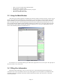
5.6 Relating Model Elements
Existing model elements can typically be put in relation to define the semantics of the model. A relation
connecting two model elements can be an association, a generalization, a dependency, an activity transition or a
collaboration link depending on the source and destination element. They look different in terms of the line
pattern. The modeler just visually connects two model elements by a line. The tool then determines the kind of
relation based on the source and destination element. (For example, when the modeler connects a holon to a joint
action, the resulting relation becomes a collaboration link.) The modeler can create a new relation with one of 3
most frequently used routing options (straight line, top-routing line and bottom-routing line).
IV Synchronization:
According to the SEAM modeling language (see Subsection 2.1), the information objects and localized
actions of a holon characterize its information viewpoint. Since there could be several holons being viewed as
whole, the diagram would be complicated if their information viewpoints are fully displayed. It is thus
essentially to display only information objects and localized actions that are relevant to the joint actions. This
kind of relevancy is determined by aligning information objects and localized actions to some joint action. We
call this functionality the synchronization between the joint actions and the information viewpoints. The
alignment is mainly applied to transactions and interaction localized actions. In fact, the modeler may find it
tedious to manually align them. For this reason, the tool can create one transaction and one localized action for a
- Page 20 -
computational object when the modeler drops a link between it and some joint action. This transaction and
localized action is then automatically aligned to the proper joint action. Once this alignment is maintained, the
localized actions are always named by capitalizing the first letter of the joint action they are aligned to. The
corresponding transactions are named by appending the postfix “Txn” to the name of that localized action. The
modeler is therefore recommended to name the joint actions using verbs in lower case (e.g. move, select, add…).
If the modeler renames the joint action, all aligned transactions and localized actions are correctly updated.
The following steps should be taken in order to relate 2 model elements:
- First, click on the button having a line icon or menu item “Tool | Insert | Straight Line” (or “Tool |
Insert | Top-routing Line” or “Tool | Insert | Bottom-routing Line”)
- Then drop into the source model element. Note that the potential source element is highlighted in
blue color.
- Next, drop into the destination element. Note that the potential destination element is highlighted in
blue color.
- The newly created relation has no name.
- The tool determines the relation based on the source and destination element. If it is a collaboration
link and the IV Automation is turned on, a transaction and a localized action are created with
appropriate names for the participating object. IV Automation is turned on by default and can be
turned off by pressing button “IV Auto” in the toolbar of the modeling window.
For example, to make PurchasingDep participate in joint action select (and so joint action market),
first the modeler click on the button having a line icon (see Figure 13 a). Next, she drops into select and then
PurchasingDep. In effect, the information viewpoint of PurchasingDep is created (see Figure 13 b) up the
detail level where joint action select is (detail level 2). In this case, dropping into select first or
PurchasingDep first does not matter. Note that the modeler has to arrange the created information objects and
localized actions at her convenience because they are partially overlapped when created by the tool.
Click here to start
creating a relation
Drop into select to
make it as the source
element of the new
relation
Drop into BookCo to
make it as the
destination element
of the new relation
Figure 13 a). Connecting joint action select to holon BookCo results in a new collaboration link.
- Page 21 -
Figure 13 b). The information viewpoint of holon BookCo are automatically created up to the detail
level where joint action select is (level 2).
5.7 Inserting a Note
Each model element except the relation can be attached some notes. A note has a name (rendered just below
the notation) and a text (rendered inside the notation). The following steps should be taken in order to insert a
note:
- First, click on the button having a folder icon or menu item “Tool | Insert | Note”.
- Then drop into a model element in the diagram. Note that the potential element is highlighted in
blue color.
- The newly created comment is given a default name and a text copied from the description of the
targeted element.
5.8 Modify an Existing Model Element
In the modeling window, the property panel at the bottom-left corner is used for editing the element selected
in the diagram. The name, stereotype, constraint and description of the selected element can be modified. If the
selected element is a relation, its roles and cardinalities can be edited in the corresponding text fields of the
property panel.
- Page 22 -
Edit the name, stereotype,
constraint and description
of the selected element
Shortcut for renaming
Predefined stereotype
for a transaction
Figure 14. The selected element can be edited in the property panel. It can also be renamed directly
inside its notation.
In addition, the context popup menu of the model element provides the modeler with shortcuts for quick and
easy modifications. Every element can be renamed by using popup menu “Rename” (see Figure 14). The
information object and localized action can be manually aligned to a specific joint action by following popup
menu “Goal”. The relation can be manually set, rerouted and toggled directed/undirected by using popup menu
“Relation”, “Routing” and (checkbox menu) “Directed” respectively. The modeler can pick a predefined
stereotype (<<transaction>>, <<concept>> and <<parameter>>) for an information object by using popup menu
“Stereotype”. Similarly, she can pick one of two predefined stereotypes <<interaction>> and <<internal>> for a
localized action in the same way.
The tool allows the modeler to change the type of an existing holon. Apparently, she can switch between a
biz object and an IT object. A human object can be changed to either a biz object or an IT object but not in the
opposite way. She can do so by using the popup menu item “Humanize”, “to Biz” or “IT systemize” of the holon
that she wants to change. Once the type of a holon is changed, the notation of that object is changed accordingly.
5.9 Delete an Existing Model Element
Right-click on the model element to activate its popup menu, then choose menu item Delete. Its component
elements and relations will be deleted as well. They are all reported in the Output Window.
5.10 Saving the Model
The newly created and modified model elements need to be updated in the database. This can be done by
using menu item “Model | Save <model name>” of the main window.
- Page 23 -
6 Miscellaneous Functionalities
This section presents miscellaneous functionalities such as saving working model, export modeling diagram
as a GIF picture, attaching a small image to a holon…
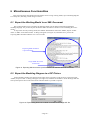
6.1 Export the Working Model to an XML Document
The working model can be exported to an XML document with an XML schema reflecting SEAM
modeling language. It is possible to pass this kind of XML document to another tool for simulating the source
model…
To export the currently working model, the modeler should follow menu item “Model | Export <model
name> to XML” of the main window. A dialog will appear (see Figure 15) and allow her to preview the
exporting XML document and then save it as a local file.
Exporting XML document
is previewed here
Target XML file can be
browsed for
Figure 15. Exporting XML document is previewed and can then be saved as a local file.
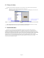
6.2 Export the Modeling Diagram to a GIF Picture
In each modeling window, the diagram on the right can be exported to a GIF picture by using menu item
“Model | Export to GIF”. A dialog will appear (see Figure 16) and allow the modeler to locate the target GIF file.
The exported picture then can be inserted into other documents or printed to a printer.
Figure 16. Export dialog allows the modeler to browse for the target GIF file.
- Page 24 -
6.3 Picture for Holon
Each holon can be attached a small image as an icon as follows. This is useful to make the model more
concrete.
- Right-click on a holon and then select menu item “Image Icon”.
- A dialog will appear to help the modeler select an icon from a predefined gallery or browse for her
favorite images (see Figure 17).
Click here to
browse for
favorite images
Click here to clear the icon
of the selected holon
Figure 17. The picture for the selected holon can be chosen from the built-in gallery or from a local file
system.
Icons can be painted in 64 x 64, 32 x 32 or not painted at all in modeling diagrams. Menu View | Image
icon of the modeling window allows the modeler to switch between these modes.
7 Tool Architecture
The server is a set of Java servlets executed within a web server at our location. These servlets are
responsible for storing and loading model elements into a database. The client is a Java application and is
available for downloading. The client and the server exchange data in XML format. Typically, the server load
elements from the database when the modeler opens a model. The server then produces an XML document form
them and send it to the client through a Web connection. The client parses this XML document to reconstruct the
model elements and then build an appropriate data structure. When working with the model, the modeler
modifies the local copy of the model. When the modeler saves her modified model, the client produces an XML
document for newly created and modified elements. The XML document is sent to the server in a Web
connection that will update the database.
- Page 25 -
Appendix A: Web Prototypes
This appendix presents the first two prototypes of SeamCAD which were built as static web pages to
illustrate the main functionalities of the tool based on a case-study. In this case-study, the modeler needs to
represent the development and the usage of a program called DrawingToolSystem (DTS) that allows the user to
draw and manipulate basic 2D shapes (circle, rectangle, group…). Specifically, the user can create a new shape,
remove the existing one as well as print all the shapes in a picture. DTS is the system of interest and needs to be
modeled as atomic and as composite through several detail levels. In Prototype 1, only DTS is represented within
a community consisting of itself, its developer and its user. In Prototype 2, two organizational levels are
represented. One level is about the DTS, the user and the developer. The other is about the Java classes that
implement DTS.
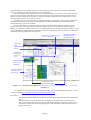
Prototype 1
Goal:
The system of interest needs to be represented with respect to the interaction with its environment. It is
represented either as atomic or as composite. Being represented as atomic, the system of interest should have
transactions and localized actions regarding the collaboration it takes part in. Being represented as composite, it
should have Java classes that implement it.
Description:
The navigation panel on the left allows the modeler to navigate in different diagrams that represent DTS,
UserPeople, DeveloperPeople collaborating through some joint actions. There are 3 detail levels that
correspond to the decomposition of joint action doLifecycle into install, execute, uninstall and into
add Shape, remove Shape, print Picture. Each cell of the navigation panel is coordinated by the way to
view DTS (as unqualified, atomic, or composite on the columns) and by a joint action (on the rows) that DTS
participates in. In principal, each cell corresponds to one diagram. In fact, not all diagrams are available. The
cells whose the corresponding diagram is available are cyan. When the modeler clicks on a cyan cell, it is
selected and becomes blue. The diagram of the selected cell is painted on the right. By default, the environment
of DTS is shown in the diagram. It is possible to hide (and later on show again) it by clicking on the link labeled
“hidden” or “visible” at the bottom of the navigation panel (see Figure 18).
There are also shortcuts inside the pictograms of objects and actions that allow the modeler to toggle
between the whole (shortcut [A]) and the composite (shortcut [C]) or even to hide them (shortcut [H]). Clicking
on the shortcut [H] of DTS - the system of interest will make it as unqualified. In addition, It is possible to isolate
a joint action or a localized action from it siblings with shortcut [Scope]. Once the diagram is changed when the
modeler follows a shortcut, the corresponding cell is selected in the navigation panel.
Prototype 1 can be reached at http://lamspeople.epfl.ch/lsle/SEAMtool/proto1/toc.htm.
- Page 26 -
Click here to
view joint action
execute as
atomic
Click here to
isolate joint action
add Shape
Click here to
select a cell and
display a diagram
Click here to
view DTS as
composite
Click here to hide (to show later
on) the environment of DTS
Figure 18. DTS as atomic with respect to add Shape, remove Shape and print Picture in
Prototype 1.
In summary, prototype 1 introduces the navigation panel, through which the modeler can view the system
of interest with respect to different joint actions that more or less denote the detail level.
Findings:
-
The only system of interest is viewed either as atomic or as composite
The system of interest as atomic is always synchronized to the joint actions represented.
Joint actions are implicitly organized into detail levels, which should be hierarchically organized.
More than one level with multiple systems of interest need to be represented.
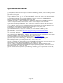
Prototype 2
Goal:
Navigation panel should allow the modeler to select the organizational level she wants to work with. She
then can view each object in the chosen level as atomic/composite. The panel should also allow her to navigate
in joint actions happening within the chosen level.
Description:
The navigation panel of the left contains
a) a slider to select one of the two organizational levels
b) a table for viewing holons that exist in the selected organizational level
c) a hierarchy of joint actions that happen between viewed objects
First, the modeler selects the organizational level of interest by clicking on a box in the slider. There are two
boxes representing level 1 (DTS collaborates with people) and level 2 (Java classes collaborate within DTS). In
the object table at the middle of the navigation panel, each row represents a holon that exists in the selected
- Page 27 -
organizational level. The columns of this table correspond to how these objects are viewed (as unqualified,
atomic or composite). Initially, all of them are seen as unqualified.
Then, the modeler chooses the detail level by clicking on the shortcut [+] of a row in the action hierarchy
(drawn as a tree structure). The table next to the action hierarchy lists all relevant joint actions at the chosen
detail level. Each of them can be isolated (or scoped) by clicking a radio button next to them. There is also a
radio button that stands for the parent joint action.
In principal, she can view each object as unqualified, atomic or composite by clicking on the appropriate
radio button in the object table. In fact, as the drawings are limited, the modeler gets a warning text if the
diagram she wants to see is not available.
There are also shortcuts inside the pictograms of objects and actions that allow the modeler to toggle
between the whole (shortcut [A]) and the composite (shortcut [C]) or even to hide them (shortcut [H]). In
addition, It is possible to isolate a joint action or a localized action from it siblings with shortcut [Scope]. As the
on the right diagram is changed when the modeler follows a shortcut, the appropriate radio button is selected or
deselected in the navigation panel (see Figure 19).
Click here to view joint action
execute as atomic
Click here to hide (to
show later on) the
environment of DTS
Click here to
select
organizational
level 2
Click here to
isolate joint
action add
Shape
Click here to
view DTS as
composite
Click here to jump
to the second
detail level
Click here to view
DTS as unqualified
Figure 19. DTS as atomic with respect to add Shape, remove Shape and print Picture in
Prototype 2.
As a comparison, Prototype 2 provides the modeler more navigation mechanisms than Prototype 1 does. It
can be reached at http://lamspeople.epfl.ch/lsle/SEAMtool/proto2/toc.htm.
Our findings:
- The navigational panel allows the modeler navigate in both the organizational level and the detail
level.
- The demonstration is good enough to start developing the first functional version of the tool.
- The synchronization between the joint actions and the participating holons seen as whole can be
realized in the functional version by aligning each of their transactions and localized actions to a
specific joint action.
- Page 28 -
Appendix B: References
[1] A. Wegmann, "On the Systemic Enterprise Architecture Methodology (SEAM)", in the proceeding of ICEIS
2003, Angers, France, 2003.
[2] J. G. Miller, Living Systems: University of Colorado Press, 1995.
[3] OMG, "ISO/IEC 10746-1, 2, 3, 4 | ITU-T Recommendation, X.901, X.902, X.903, X.904, Reference Model
of Open Distributed Processing", 1995-1996.
[4] A. Wegmann, Naumenko, A., "Conceptual Modeling of Complex Systems using an RM-ODP based
Ontology", in the proceeding of EDOC 2001, Seattle, USA, 2001.
[5] B. Schätz, Pretschner, A., Huber, F., Philipps, J., "Model-based development of embedded systems", in In
Advances in Object-Oriented Information Systems, Lecture Notes in Computer Science 2426, 2002.
[6] D. Francis D'souza, Cameron Wills, A., Object, Components and Frameworks with UML, The Catalysis
Approach: Addison-Wesley, 1999.
[7] J. L. L. Moigne, "Que sais-je? Les épistemologies constructivistes": Presses Universitaires de France, 1995.
[8] R. Audi, The Cambridge Dictionary of Philosophy: Cambridge University Press, 1999.
[9] A. Koestler, The Art of Creation: Penguin Group, 1964.
[10] P. Checkland, Scholes, J., Soft System Methodology in action: Chichester UK: Wiley, 1990.
[11] M. E. Porter, Competitive Advantage: Free Press, 1985.
[12] OMG, UML 1.5 Specification, http://www.omg.org/technology/documents/formal/uml.htm
[13] A. Naumenko, Wegmann, A., "A Metamodel for the Unified Modeling Language", in the proceeding of
<<UML>> 2002, Dresden, Germany, 2002.
[14] C. Atkinson, Paech, B., Reinhold, J., Sander, T., "Developing and applying component-based model-driven
architectures in KobrA", in the proceeding of EDOC 2001, Seattle, USA, 2001.
[15] System Engineering Conceptual Model (Work in Process), http://syseng.omg.org
[16] D. Dori, Object-Process Methodology, A Holistic Systems Paradigm: Springer Verlag, 2002.
[17] D. Dori, Reinhartz-Beger, I., Sturm, A., "OPCAT - A Bimodal CASE Tool for Object-Process Based
System Development", in the proceeding of ICEIS 2003, Angers, France, 2003.
[18] L. S. Lê, Wegmann, A., "Meta-model for Object-Oriented Hierarchical Systems", School of Computer and
Communication Sciences, EPFL, Lausanne, Report No. IC/2004/47, May 2004
[19] J. A. Zachman, "A Framework for Information System Architecture", IBM System Journal, 1988.
[20] Y. Gurevich, "Sequential Abstract State Machines Capture Sequential Algorithms", ACM Transactions on
Computational Logic, vol. 1, pp. 77-111, 2000.
[21] J. D. Sterman, Business Dynamics - Systems Thinking and Modeling for a Complex World: McGraw-Hill,
2000.
- Page 29 -