1
2416 Monocolor LED 3mm/5mm
Dot Matrix Display
Information Board
User’s Guide
© 2004-2009 Sure Electronics Inc.
DE-DP11111&DE-DP11112&DE-DP11211&DE-DP11212 _Ver2.0
2416 MONOCOLOR LED 3MM/5MM
DOT MATRIX DISPLAY
INFOMATION BOARD
USER’S GUIDE
Table of Contents
Chapter 1. Overview ..........................................................................................................1
1.1 Overview .............................................................................................................. 1
1.2 Quick Start ........................................................................................................... 3
1.2.1 Connection of One Info Board and The Driver Board .................................... 3
1.2.2 Connection of Many Info Boards (Max 4 Boards)............................................ 5
Chapter 2. Hardware Detail ...............................................................................................7
2.1
2.2
2.3
2.4
2.5
Hardware.............................................................................................................. 7
Port Definition ..................................................................................................... 7
Display Memory................................................................................................... 8
Command Format ............................................................................................... 9
Command Summary ......................................................................................... 10
Chapter 3. Electrical Characteristics .............................................................................12
Chapter 4. Mechanical Drawing......................................................................................13
Chapter 5. Appendix ........................................................................................................14
5.1 Schematic .......................................................................................................... 14
5.2 Sample Code ..................................................................................................... 14
5.3 Heat Dissipation ................................................................................................ 20
Chapter 6. Contact Us .....................................................................................................23
© 2004-2009 Sure Electronics Inc.
DE-DP11111&DE-DP11112&DE-DP11211&DE-DP11212_Ver2.0_Page i
2416 Monocolor LED 3mm/5mm Dot Matrix Display Information Board
NOTES:
Product Version
:
Ver 1.0
Document Version
:
Ver 2.0
DE-DP11111&DE-DP11112&DE-DP11211&DE-DP11212_Ver2.0_Page ii
© 2004-2009 Sure Electronics Inc
2416 MONOCOLOR LED 3MM/5MM
DOT MATRIX DISPLAY
INFORMATION BOARD
USER’S GUIDE
Chapter 1. Overview
1.1 Overview
Thanks for using 2416 monocolor LED dot matrix info board series by Sure Electronics.
Each integrating HT1632C as the driver chip, these info boards support 16-level PWM
brightness control and all LED dot matrixes displayed are mapped to the RAM of
HT1632C. Peripheral circuits are required to light up LEDs via the ports on the boards.
These info boards can be used to display digits, letters and even graphs. It is allowed to
connect up to 4 boards of the same kind in series for wider applications such as info
display in banks, stores, households and so on. You may refer to the following table for
members of this series.
TABLE 1-1 2416 MONOCOLOR LED DOT MATRIX DISPLAY INFO BOARD SERIES
Product Number
Product Name
DE-DP11111
2416 Green LED 3mm Dot Matrix Display Information Board
DE-DP11112
2416 Red LED 3mm Dot Matrix Display Information Board
DE-DP11211
2416 Green LED 5mm Dot Matrix Display Information Board
DE-DP11212
2416 Red LED 5mm Dot Matrix Display Information Board
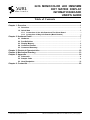
FIGURE 1-1 FRONT VIEW OF 2416 3MM DOT MATRIX DISPLAY INFO BOARD
© 2004-2009 Sure Electronics Inc.
DE-DP11111&DE-DP11112&DE-DP11211&DE-DP11212_Ver2.0_Page 1
2416 Monocolor LED 3mm/5mm Dot Matrix Display Information Board
FIGURE 1-2 FRONT VIEW OF 2416 5MM DOT MATRIX DISPLAY INFO BOARD
FIGURE 1-3 BACK VIEW OF 2416 3MM DOT MATRIX DISPLAY INFO BOARD
DE-DP11111&DE-DP11112&DE-DP11211&DE-DP11212_Ver2.0_Page 2
© 2004-2009 Sure Electronics Inc
Overview
FIGURE 1-4 BACK VIEW OF 2416 5MM DOT MATRIX DISPLAY INFO BOARD
Note: All diagrams in this manual are for reference only.
1.2 Quick Start
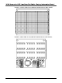
A 16-pin IDC cable and two power cords are provided for free. DE-DD210 by Sure
Electronics is used in this manual as a driver board. Program this driver board to control
the display on the info board.
FIGURE 1-5 ACCESSORIES
Note:
1. Other driver board can be used. You may refer to 2.2 Port Definition to do relative
adjustments.
2. Sample codes are provided in this manual for reference.
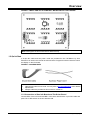
1.2.1 Connection of One Info Board and The Driver Board
Connect BR1 of the info board and BR1 of the driver board with a 16-pin IDC cable and
push CS1 of DIP switch on the info board to ON.
© 2004-2009 Sure Electronics Inc.
DE-DP11111&DE-DP11112&DE-DP11211&DE-DP11212_Ver2.0_Page 3
2416 Monocolor LED 3mm/5mm Dot Matrix Display Information Board
FIGURE 1-6 CONNECTION OF THE DRIVER BOARD AND ONE 2416 3MM DOT
MATRIX DISPLAY INFO BOARD
DE-DP11111&DE-DP11112&DE-DP11211&DE-DP11212_Ver2.0_Page 4
© 2004-2009 Sure Electronics Inc
Overview
FIGURE 1-7 CONNECTION OF THE DRIVER BOARD AND ONE 2416 5MM DOT
MATRIX DISPLAY INFO BOARD
Program codes to the chip of the driver board and repower the board.
Note: If you’re not familiar with programming, try using the sample codes first.
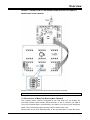
1.2.2 Connection of Many Info Boards (Max 4 Boards)
First, auxiliary power cords are suggested to be used when four info boards are
connected in series via the auxiliary power terminals: J1 and J2. Connect +5V, GND of
J2 on one info board and the corresponding +5V, GND of J1 on the next info board with
power cords. The auxiliary supply should be able to output DC5V 1.5A.
Connect BR1 of the driver board and BR1 of the info board with a 16-pin IDC cable.
© 2004-2009 Sure Electronics Inc.
DE-DP11111&DE-DP11112&DE-DP11211&DE-DP11212_Ver2.0_Page 5
2416 Monocolor LED 3mm/5mm Dot Matrix Display Information Board
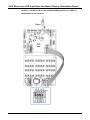
Then, as shown in figure 1-8, connect four 2416 info boards and the driver board with
16-pin IDC cables and power cords. Set the CS1 of SW1 of the first info board, CS2 of
the second info board, CS3 of the third info board and CS4 of the fourth info board ON.
FIGURE 1-8 CONNECTION OF FOUR 2416 3MM DOT MATRIX DISPLAY INFO
BOARDS CONNECTED IN SERIES
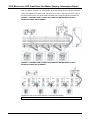
FIGURE 1-9 CONNECTION OF FOUR 2416 5MM DOT MATRIX DISPLAY INFO
BOARDS CONNECTED IN SERIES
Program the chip on the driver board to control the LED display.
Note: If you use the sample codes, all the boards will display the same content.
DE-DP11111&DE-DP11112&DE-DP11211&DE-DP11212_Ver2.0_Page 6
© 2004-2009 Sure Electronics Inc
2416 MONOCOLOR LED 3MM/5MM
DOT MATRIX DISPLAY
INFORMATION BOARD
USER’S GUIDE
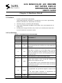
Chapter 2. Hardware Detail
2.1 Hardware
1.
6 pieces of 8*8 LED dot matrix display
Light-emitting diameter of DE-DP11111 and DE-DP11112 is 3mm. Light-emitting
diameter of DE-DP11211 and DE-DP11212 is 5mm
2.
LED drive chip (U1): HT1632C, QFP packaging.
3.
16-pin male sockets (BR1 and BR2): used for data, clock, control signal and +5V
supply input.
4.
Auxiliary power supply terminals (+5V) (J1and J2): for external power input when
more info boards are connected in series.
2.2 Port Definition
TABLE 2-1 PIN DEFINITION OF BR1 AND BR2
Pin Number
Pin Name
Function Description
1
CS1
Chip Selection 1
2
CS2
Chip Selection 2
3
CS3
Chip Selection 3
4
CS4
Chip Selection 4
WRITE clock input with pull-high resistor Data on the DATA
5
WR
lines are latched into the HT1632C on the rising edge of the
WR signal.
READ clock input with pull-high resistor. The HT1632C
RAM data is clocked out on the falling edge of the RD
6
RD
signal. The clocked out data will appear on the DATA line.
The host controller can use the next rising edge to latch the
clocked out data.
7
DATA
Serial data input or output with pull-high resistor
If the RC Master Mode command is programmed, the
system clock source is from on-chip RC oscillator and
9
OSC
system clock is output to OSC pin.
If the Slave Mode or EXT CLK Master Mode command is
programmed, the system clock source is input from external
clock via the OSC pin
If the RC Master Mode or EXT CLK Master Mode command
is programmed, the synchronous signal is output to SYN
10
SYNC
pin.
If
the
Slave
Mode
command
is
programmed, the
synchronous signal is input from SYN pin.
8, 11, 13, 15
GND
GND
12, 14, 16
VCC
Power Supply
© 2004-2009 Sure Electronics Inc.
DE-DP11111&DE-DP11112&DE-DP11211&DE-DP11212_Ver2.0_Page 7
2416 Monocolor LED 3mm/5mm Dot Matrix Display Information Board
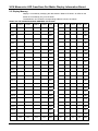
2.3 Display Memory
Display is controlled by modifying the data stored in RAM of HT1632C. All LEDs on the
board are controlled by only one HT1632C.
The distribution of HT1632C’s corresponding address is shown as follows:
TABLE 2-2 THE CORRESPONDING ADDRESS OF HT1632C
COM15
COM14
COM13
COM12
Addr
…
COM3
COM2
COM1
COM0
Addr
OUT0
03H
00H
OUT1
07H
04H
OUT2
0BH
08H
OUT3
0FH
0CH
OUT4
13H
10H
OUT5
17H
14H
OUT6
1BH
18H
OUT7
1FH
1CH
OUT8
23H
20H
OUT9
27H
24H
OUT10
2BH
OUT11
2FH
2CH
OUT12
33H
30H
OUT13
37H
34H
OUT14
3BH
38H
OUT15
3FH
3CH
OUT16
43H
40H
OUT17
47H
OUT18
4BH
48H
OUT19
5FH
4CH
OUT20
53H
50H
OUT21
57H
54H
OUT22
5BH
58H
OUT23
5FH
D15
D14
D13
D12
Data
DE-DP11111&DE-DP11112&DE-DP11211&DE-DP11212_Ver2.0_Page 8
28H
…
…
44H
…
5CH
D3
D2
D1
D0
Data
© 2004-2009 Sure Electronics Inc
Hardware Detail
FIGURE 2-1 THE CORRESPONDING ADDRESS OF HT1632C ON 2416 3MM DOT
MATRIX DISPLAY INFO BOARD
FIGURE 2-2 THE CORRESPONDING ADDRESS OF HT1632C ON 2416 5MM DOT
MATRIX DISPLAY INFO BOARD
2.4 Command Format
CS (CS1、CS2、CS3、CS4) of HT1632C must be set to low before data or command is
sent to this HT1632C. When the transmission is complete, CS must be reset to high.
The timing diagram is as follows:
© 2004-2009 Sure Electronics Inc.
DE-DP11111&DE-DP11112&DE-DP11211&DE-DP11212_Ver2.0_Page 9
2416 Monocolor LED 3mm/5mm Dot Matrix Display Information Board
FIGURE 2-3 SEND DATA
FIGURE 2-4 SEND COMMAND
Note: You may refer to HT1632C data sheet for details.
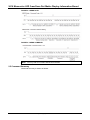
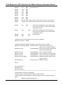
2.5 Command Summary
Command summary is shown as follows.
DE-DP11111&DE-DP11112&DE-DP11211&DE-DP11212_Ver2.0_Page 10
© 2004-2009 Sure Electronics Inc
Hardware Detail
FIGURE 2-5 COMMAND SUMMARY
© 2004-2009 Sure Electronics Inc.
DE-DP11111&DE-DP11112&DE-DP11211&DE-DP11212_Ver2.0_Page 11
2416 MONOCOLOR LED 3MM/5MM
DOT MATRIX DISPLAY
INFORMATION BOARD
USER’S GUIDE
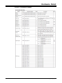
Chapter 3. Electrical Characteristics
TABLE 3-1 ELECTRICAL CHARACTERISTICS
Parameter
Symbol
Value
Unit
Operating Voltage
Vin
5
V
Storage Temperature
Tstg
-20 to 80
℃
Average Operating Current
Iavrg
0.20
A
Operating
DE-DP11111
Current (All LEDs on,
DE-DP11112
100%
DE-DP11211
Maximum
cycle)
PWM
duty
DE-DP11212
DE-DP11111&DE-DP11112&DE-DP11211&DE-DP11212_Ver2.0_Page 12
0.35
Imax
0.27
0.33
A
0.27
© 2004-2009 Sure Electronics Inc.
2416 MONOCOLOR LED 3MM/5MM
DOT MATRIX DISPLAY
INFORMATION BOARD
USER’S GUIDE
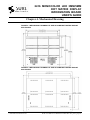
Chapter 4. Mechanical Drawing
FIGURE 4-1 MECHANICAL DRAWING OF ONE 2416 3MM DOT MATRIX DISPLAY
INFO BOARD
FIGURE 4-2 MECHANICAL DRAWING OF ONE 2416 5MM DOT MATRIX DISPLAY
INFO BOARD
© 2004-2009 Sure Electronics Inc.
DE-DP11111&DE-DP11112&DE-DP11211&DE-DP11212_Ver2.0_Page 13
Cathode0
Cathode1
Cathode2
Cathode3
Cathode4
Cathode5
Cathode6
Cathode7
Cathode8
Cathode9
Cathode10
Cathode11
Cathode12
Cathode13
Cathode14
Cathode15
Cathode16
Cathode17
Cathode18
Cathode19
Cathode20
Cathode21
Cathode22
Cathode23
Anode15
Anode14
Anode13
Anode12
Anode11
Anode10
Anode9
Anode8
13
12
11
10
9
8
6
5
4
3
2
1
52
51
50
49
48
47
46
45
44
43
42
41
40
39
37
35
34
33
32
31
22
19
16
13
3
6
9
12
Anode8
Anode9
Anode10
Anode11
Anode12
Anode13
Anode14
Anode15
Cathode[0..23]
23
20
17
14
2
5
8
11
23
20
17
14
2
5
8
11
HT1632C/QFP-52
52-pin QFP
ROW0
ROW1
ROW2
ROW3
ROW4
ROW5
ROW6
ROW7
ROW8
ROW9
ROW10
ROW11
ROW12
ROW13
ROW14
ROW15
ROW16
ROW17
ROW18
ROW19
ROW20
ROW21
ROW22
ROW23
ROW24/COM15
ROW25/COM14
ROW26/COM13
ROW27/COM12
ROW28/COM11
ROW29/COM10
ROW30/COM9
ROW31/COM8
U1
LED
D4
24
21
18
15
1
4
7
10
24
21
18
15
1
4
7
10
LED
VDD
OSC
SY NC
CS
RD
WR
DATA
COM0
COM1
COM2
COM3
COM4
COM5
COM6
COM7
VSS
LED_VSS_1
LED_VSS_2
25
36
14
7
38
21
15
20
19
18
17
16
22
23
24
26
27
28
29
30
220R
220R
220R
220R
220R
220R
220R
220R
LED_VDD_1
LED_VDD_2
R73
R76
R79
R82
R85
R88
R91
R94
220R
220R
220R
220R
220R
220R
220R
220R
220R
220R
220R
220R
220R
220R
220R
220R
R25
R28
R31
R34
R37
R40
R43
R46
R49
R52
R55
R58
R61
R64
R67
R70
220R
220R
220R
220R
220R
220R
220R
220R
R1
R4
R7
R10
R13
R16
R19
R22
R97
R98
33R
33R
Anode0
Anode1
Anode2
Anode3
Anode4
Anode5
Anode6
Anode7
Cathode7
Cathode6
Cathode5
Cathode4
Cathode3
Cathode2
Cathode1
Cathode0
Cathode0
Cathode1
Cathode2
Cathode3
Cathode4
Cathode5
Cathode6
Cathode7
Cathode7
Cathode6
Cathode5
Cathode4
Cathode3
Cathode2
Cathode1
Cathode0
Cathode0
Cathode1
Cathode2
Cathode3
Cathode4
Cathode5
Cathode6
Cathode7
+5V
OSC
SY NC
ChipCS
RD
WR
DATA
LED
D5
LED
D2
BR1
CS1
CS2
CS3
2
4
6
8
10
12
14
16
ChipCS
MSV8X2
1
3
5
7
9
11
13
15
R100 R101 R102
CS1
CS3
WR
DATA
OSC
22
19
16
13
3
6
9
12
22
19
16
13
3
6
9
12
CS4
220R 220R 220R 220R
R99
Anode8
Anode9
Anode10
Anode11
Anode12
Anode13
Anode14
Anode15
Anode0
Anode1
Anode2
Anode3
Anode4
Anode5
Anode6
Anode7
CS2
CS4
RD
SW DIP-4
SW1
SY NC
23
20
17
14
2
5
8
11
23
20
17
14
2
5
8
11
+5V
R74
R77
R80
R83
R86
R89
R92
R95
R50
R53
R56
R59
R62
R65
R68
R71
R26
R29
R32
R35
R38
R41
R44
R47
R2
R5
R8
R11
R14
R17
R20
R23
+
+5V
+5V
Cathode15
Cathode14
Cathode13
Cathode12
Cathode11
Cathode10
Cathode9
Cathode8
220R
220R
220R
220R
220R
220R
220R
220R
16V 100uF
C8
C3
104
+5V
Cathode8
Cathode9
Cathode10
Cathode11
Cathode12
Cathode13
Cathode14
Cathode15
220R
220R
220R
220R
220R
220R
220R
220R
C4
104
2
4
6
8
10
12
14
16
+
+5V
+5V
+5V
16V 100uF
C9
C5
104
MSV8X2
1
3
5
7
9
11
13
15
BR2
Cathode15
Cathode14
Cathode13
Cathode12
Cathode11
Cathode10
Cathode9
Cathode8
220R
220R
220R
220R
220R
220R
220R
220R
CS1
CS3
WR
DATA
OSC
Cathode8
Cathode9
Cathode10
Cathode11
Cathode12
Cathode13
Cathode14
Cathode15
220R
220R
220R
220R
220R
220R
220R
220R
C6
104
SY NC
+5V
C7
104
+5V
22
19
16
13
3
6
9
12
Anode8
Anode9
Anode10
Anode11
Anode12
Anode13
Anode14
Anode15
CS2
CS4
RD
22
19
16
13
3
6
9
12
Anode0
Anode1
Anode2
Anode3
Anode4
Anode5
Anode6
Anode7
+
+5V
LED
D6
LED
D3
24
21
18
15
1
4
7
10
16V 22uFtan
C1
+
+5V
24
21
18
15
1
4
7
10
D1
24
21
18
15
1
4
7
10
24
21
18
15
1
4
7
10
8
7
6
5
1
2
3
4
22
19
16
13
3
6
9
12
1
2
Anode0
Anode1
Anode2
Anode3
Anode4
Anode5
Anode6
Anode7
1
2
1
2
DE-DP11111&DE-DP11112&DE-DP11211&DE-DP11212_Ver2.0_Page 14
1
#ifndef
2
Anode[0..15]
16V 22uFtan
C2
23
20
17
14
2
5
8
11
23
20
17
14
2
5
8
11
+5V
220R
220R
220R
220R
220R
220R
220R
220R
R75
R78
R81
R84
R87
R90
R93
R96
+5V
Cathode16
Cathode17
Cathode18
Cathode19
Cathode20
Cathode21
Cathode22
Cathode23
220R
220R
220R
220R
220R
220R
220R
220R
R39
R42
R45
R60
R63
R66
R69
R72
MSV2
1
2
J2
MSV2
1
2
J1
Cathode23
Cathode22
Cathode21
Cathode20
Cathode19
Cathode18
Cathode17
Cathode16
Cathode23
Cathode22
Cathode21
Cathode20
Cathode19
Cathode18
Cathode17
Cathode16
220R
220R
220R
220R
220R
220R
220R
220R
R27
R48
R51
R54
R57
R30
R33
R36
Cathode16
Cathode17
Cathode18
Cathode19
Cathode20
Cathode21
Cathode22
Cathode23
220R
220R
220R
220R
220R
220R
220R
220R
R3
R6
R9
R12
R15
R18
R21
R24
2416 MONOCOLOR LED 3MM/5MM
DOT MATRIX DISPLAY
INFORMATION BOARD
USER’S GUIDE
Chapter 5. Appendix
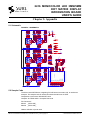
5.1 Schematic
FIGURE 5-1 SCHEMATIC
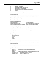
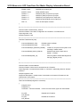
5.2 Sample Code
The driver board DE-DD210, integrating PIC16F723 as its master chip, is used as an
example. This sample code is used to illuminate the odd rows of LEDs.
Compilation environment: MPLAB IDE v8.40
Compiler: HI-TECH ANSI C Compiler PRO 9.65
File “Declare.h”
_DECLARE_
#define _DECLARE_
//Macro definition of ports used
© 2004-2009 Sure Electronics Inc.
2416 Monocolor LED 3mm/5mm Dot Matrix Display Information Board
#define
CS1
RB0
#define
CS2
RB1
#define
CS3
RB2
#define
CS4
RB3
#define
CS5
RB4
#define
CS6
RB5
#define
CS7
RB6
#define
CS8
RB7
//8 control ports
#define
CS_OFF CS1=1;CS2=1;CS3=1;CS4=1;CS5=1;CS6=1;CS7=1;CS8=1;
#define
CS_ON CS1=0;CS2=0;CS3=0;CS4=0;CS5=0;CS6=0;CS7=0;CS8=0;
#define
CLK
RC3
//Clock line simulating SPI communication (this
//port is also the clock line of SPI communication
//integrated by MCU)
#define
DAT
RC5
//Data line simulating SPI communication (this
//port is also the data line of SPI communication
//integrated by MCU)
#define
SW1
RC0
#define
SW2
RC1
//Two switches
//Following is the functions defined in a way of macro definition.
#define CLK_DELAY;
NOP()
//Following definition facilitates compilation of HT1632C control commands.
#define RC_MASTER_MODE
0b100000110000 //Set master mode and clock
//source from on-chip RC oscillator
#define SYS_DIS
0b100000000000 //Turn off both system oscillator and
//LED duty cycle generator
#define SYS_EN
0b100000000010 //Turn on system oscillator
#define LED_OFF
0b100000000100 //Turn off LED duty cycle generator
#define LED_ON
0b100000000110 //Turn on LED duty cycle generator
#define N_MOS_COM16
0b100001001000 //N-MOS open drain output and 16
//common option
#define PWM_16
0b100101011110 //PWM 16/16 duty
#endif
File “SampleCode.c”
#include <pic.h>
#include "Declare.h"
//**************************************************************************************************
//Function Name: device file configuration
//Function Feature: configure MCU’s working modes and status
//Input Argument: INTIO: INTOSCIO- internal oscillator, OSC1 and OSC2 used as I/O
//ports
//
© 2004-2009 Sure Electronics Inc.
WDTDIS: Disable watchdog timer
DE-DP11111&DE-DP11112&DE-DP11211&DE-DP11212_Ver2.0_Page 15
Appendix
//
PWRTDIS: Disable power-delay timer
//
MCLREN: Enable MCLR
//
UNPROTECT: Do NOT protect the code
//
BORDIS: Brown out reset disable
//
BORV25: Brown-out reset voltage set to 2.5V nominal
//
PLLEN:
//
DEBUGEN: In-circuit debugger enabled
//
//
VCAPDIS: Voltage regulator capacitor disable
//Output Argument: void
//**************************************************************************************************
__CONFIG(INTIO & WDTDIS & PWRTEN & MCLREN & UNPROTECT & BORDIS &
BORV25 & PLLEN & DEBUGEN);
__CONFIG(VCAPDIS);
//Function Prototype Declaration
void SystemInit(void);
//System Initialization
void SetHT1632As2416(void);
//Set HT1632C to work in 24*16 mode
void CommandWrite(unsigned int command);
//Write commands to all HT1632Cs
void AddressWrite(unsigned char address);
//Write address
void SPI_ModelConfigure(void);
//Configure data transfer mode as SPI
//mode
void SPI_DataSend(const unsigned char data); //Send data in SPI mode
void Print(void);
//Function displayed on the board
void main()
{
SystemInit();
SetHT1632As2416();
CS_ON;
Print();
while(1);
}
//**************************************************************************************************
//Function Name: system initialization
//Function Feature: set corresponding data reading and writing of PORTB and PORTC
//Input Argument: void
//Output Argument: void
//**************************************************************************************************
void SystemInit(void)
{
IRCF1 = 1;
//Set the frequency of the internal oscillator as 8MHz
IRCF0 = 0;
BRGH=0;
//Select low baud rate mode, default status after power-on reset
OSCTUNE = 0x1f;
//Oscillator at the maximum frequency
ANSELB = 0x00;
//PORTB as a digital I/O port
DE-DP11111&DE-DP11112&DE-DP11211&DE-DP11212_Ver2.0_Page 16
© 2004-2009 Sure Electronics Inc
2416 Monocolor LED 3mm/5mm Dot Matrix Display Information Board
TRISB = 0x00;
//PORTB as an output port
PORTB = 0x00;
//Clear PORTB output
TRISC0 = 1;
//PORTC0 (SW1 port) as an input port
TRISC1 = 1;
//PORTC1 (SW2 port) as an input port
TRISC3 = 0;
//PORTC3 (CLK signal) as an output port
TRISC5 = 0;
//PORTC5 (DATA signal) as an output port
T0IE = 0;
//Turn off interruption of timer0
}
//**************************************************************************************************
//Function Name: SetHT1632C_As2416
//Function Feature: write basic configuration to HT1632C in command words
//Input Argument: void
//Output Argument: void
//**************************************************************************************************
void SetHT1632As2416(void)
{
CommandWrite(SYS_EN);
//Enable system oscillator
CommandWrite(LED_ON);
//Turn on LED
CommandWrite(RC_MASTER_MODE);
// Select on-chip RC as the system clock
//working in master mode
CommandWrite(N_MOS_COM16);
//N-MOS open-drain output and 24
//ROW * 16 COM
CommandWrite(PWM_16);
//Set the grade of initial PWM brightness
//as light_degree (16/16)
}
//**************************************************************************************************
//Function Name: CommandWrite
//Function Feature: Write control commands to all HT1632Cs
//Input Argument: command words written to “command”, specifically stated in “declare”
//function
//Output Argument: void
//Argument Description: compile control commands to all external HT1632Cs for the
//requirement of the project
//**************************************************************************************************
void CommandWrite(unsigned int command)
{
unsigned char i;
unsigned int j;
command = command & 0x0fff; //12-bit command word, upper four bits masked
CS_OFF;
//Disable all HT1632Cs
CLK_DELAY;
CS_ON
//Enable all HT1632Cs
CLK_DELAY;
© 2004-2009 Sure Electronics Inc.
DE-DP11111&DE-DP11112&DE-DP11211&DE-DP11212_Ver2.0_Page 17
Appendix
for(i=0; i<12; i++)
//Write command words in HI1632C register
{
CLK = 0;
CLK_DELAY;
j = command & 0x0800;
//Return the MSB
command = command << 1; //Shift left once
j = j >> 11;
//Position the value at the LSB
DAT = j;
//Send the value to the data port
CLK_DELAY;
CLK = 1;
//Data transmission (data valid on rising edge)
CLK_DELAY;
}
CS_OFF;
//Disable all HT1632Cs
}
//**************************************************************************************************
//Function Name: AddressWrite
//Function Feature: write start address of data to HT1632C
//Input Argument: address: address to be written
//Output Argument: void
//**************************************************************************************************
void AddressWrite(unsigned char address)
{
unsigned char i,temp;
SSPCON = 0x11;
address = address & 0x7f;
//7-bit address, mask the MSB
CLK = 0;
//Clock line is 0
CLK_DELAY;
DAT = 1;
//Send “1” to data port
CLK_DELAY;
CLK = 1;
//Data transmission
CLK_DELAY;
CLK = 0;
CLK_DELAY;
DAT = 0;
//Send “0” to data port
CLK_DELAY;
CLK = 1;
//Data transmission
CLK_DELAY;
CLK = 0;
CLK_DELAY;
DAT = 1;
//Send “1” to data port
CLK_DELAY;
CLK = 1;
//Data transmission
CLK_DELAY;
for(i=0; i<7; i++)
//Write “address” to HT1632C register
{
DE-DP11111&DE-DP11112&DE-DP11211&DE-DP11212_Ver2.0_Page 18
© 2004-2009 Sure Electronics Inc
2416 Monocolor LED 3mm/5mm Dot Matrix Display Information Board
CLK = 0;
//Clock line is 0
CLK_DELAY;
temp = address & 0x40;
//Return the MSB
address = address << 1;
//Shift left once
temp = temp >> 6;
//Position the value at the LSB
DAT = temp;
//Send the value to the data port
CLK_DELAY;
CLK = 1;
//Data transmission
CLK_DELAY;
}
}
//**************************************************************************************************
//Function Name: SPI_ModelConfigure
//Function Feature: configure the corresponding data transfer port of PIC microcontroller
//for SPI communication
//Input Argument: void
//Output Argument: void
//**************************************************************************************************
void SPI_ModelConfigure(void)
{
SSPIF = 0;
//Initial state: waiting to send data
SSPCON = 0x31; //Write in this register: SSPEN=1 (enable serial port); CKP=1
//(CLK high in an idle state); CLK is FOSC/16
SSPSTAT = 0x80; // Write in this register: SMP=1(Input data sampled at end of
//data output time); CKE=0(data stable on rising edge of SCK)
}
//**************************************************************************************************
//Function Name: SPI_DataSend
//Function Feature: transmit data in SPI mode of PIC microcontroller
//Input Argument: data: bytes of data to be transmitted
//Output Argument: void
//**************************************************************************************************
void SPI_DataSend(const unsigned char data)
{
SSPBUF = data;
//Start sending
while(!SSPIF);
//Wait for data being sent
SSPIF = 0;
//Clear flag
}
//**************************************************************************************************
//Function Name: PrintString
//Function Feature: up to 4 ASCII chars to be sent
//Input Argument: string: strings to be sent
//Output Argument: void
© 2004-2009 Sure Electronics Inc.
DE-DP11111&DE-DP11112&DE-DP11211&DE-DP11212_Ver2.0_Page 19
Appendix
//**************************************************************************************************
void Print()
{
unsigned char i = 0;
unsigned char buff = 0x00;
AddressWrite(0x00);
SPI_ModelConfigure();
for(i=0; i<48; i++)
{
buff = 0xaa;
SPI_DataSend(buff);
}
SSPCON = 0x11;
}
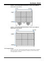
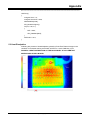
5.3 Heat Dissipation
Following are pictures of heat dissipation gained by Fluke Ti20 Thermal Imager in the
condition of info board working at full load, all LEDs on, 100% PWM duty cycle.
FIGURE 5-2 HEAT DISTRIBUTION OF THE BACK PANEL OF 2416 3MM DOT
MATRIX DISPLAY INFO BOARD
DE-DP11111&DE-DP11112&DE-DP11211&DE-DP11212_Ver2.0_Page 20
© 2004-2009 Sure Electronics Inc
2416 Monocolor LED 3mm/5mm Dot Matrix Display Information Board
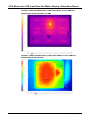
FIGURE 5-3 HEAT DISTRIBUTION OF THE BACK PANEL OF 2416 5MM DOT
MATRIX DISPLAY INFO BOARD (TA=19℃)
FIGURE 5-4 HEAT DISTRIBUTION OF THE FRONT PANEL OF 2416 3MM DOT
MATRIX DISPLAY INFO BOARD
© 2004-2009 Sure Electronics Inc.
DE-DP11111&DE-DP11112&DE-DP11211&DE-DP11212_Ver2.0_Page 21
Appendix
FIGURE 5-5 HEAT DISTRIBUTION OF THE FRONT PANEL OF 2416 5MM DOT
MATRIX DISPLAY INFO BOARD(TA=19℃)
DE-DP11111&DE-DP11112&DE-DP11211&DE-DP11212_Ver2.0_Page 22
© 2004-2009 Sure Electronics Inc
2416 MONOCOLOR LED 3MM/5MM
DOT MATRIX DISPLAY
INFORMATION BOARD
USER’S GUIDE
Chapter 6. Contact Us
Sure Electronics Co., Ltd.
5F, Zone A,
Qinhuai Technology Innovation Center
105-2 DaMing Rd (ZIP:210022)
Nanjing
P.R.China
Tel:
+86-13601408832 (For technical questions only)
+86-25-66606340 (English service, from GMT1-10AM)
Fax:
+86-25- 66606341-866
Website:
www.sure-electronics.com
www.sure-electronics.net
© 2004-2009 Sure Electronics Inc.
DE-DP11111&DE-DP11112&DE-DP11211&DE-DP11212_Ver1.0_Page 23