1
Personal Electronic Math Tutor
Final Design Report
Jeremy Ashinghurst
Scott Eshleman
Phil Gilde
May 9, 2008
Table of Contents
ACKNOWLEDGMENTS ................................................................................................. 3
ABSTRACT....................................................................................................................... 4
1.
2.
3.
4.
INTRODUCTION ...................................................................................................... 5
1.1
Description....................................................................................................... 5
1.2
Objectives ........................................................................................................ 5
1.3
Literature Review ........................................................................................... 6
1.4
Solution........................................................................................................... 11
DESIGN PROCESS............................................................................................... 13
2.1
Overall Design............................................................................................... 13
2.2
Hardware Design .......................................................................................... 14
2.3
Software Design ........................................................................................... 18
IMPLEMENTATION............................................................................................... 21
3.1
Construction .................................................................................................. 21
3.2
Operation........................................................................................................ 23
PROJECT MANAGEMENT ................................................................................. 26
4.1
Project Organization ................................................................................... 26
4.2
Scheduling ..................................................................................................... 27
5.
BUDGET .................................................................................................................. 29
6.
CONCLUSIONS ..................................................................................................... 30
7.
FUTURE WORK..................................................................................................... 31
APPENDIX A .................................................................................................................. 32
APPENDIX B .................................................................................................................. 33
APPENDIX C .................................................................................................................. 33
APPENDIX D .................................................................................................................. 34
APPENDIX E .................................................................................................................. 37
2
ACKNOWLEDGMENTS
The Personal Electronic Math Tutor team would personally like to thank both the
Engineering Department of Messiah College and the Education Group of the
Collaboratory for its financial contributions to this project. Through the donations
from the Engineering Department, our group was able to purchase all parts and
work necessary for the completion of our first prototype. The Education Group
has also kindly offered to oversee the production and implementation of this
product as the work continues.
We would also like to thanks our advisor, Dr. David Gray, for all the time and
insight he has given us over this past year. His suggestions have many times
been quite helpful and his constant encouragement has helped us to stay on
schedule. We also thank him for reviewing our written documents as well.
We would also like to thank Dr. Donald Pratt for both his leading of the Senior
Project class as well as the help and input he gave us several times on this
project. His knowledge of battery charging characteristics also became quite
useful when trying to select an appropriate battery type to power our device.
Lastly, we would like to also thank Steven Frank for the hardware help he gave to
this team in the development stages of the circuitry. His suggestions helped to
alleviate much frustration and minimized the possible mistakes we could have
made.
Sincerely,
Jeremy Ashinghurst
Scott Eshleman
Phil Gilde
3
ABSTRACT
The Burkina Math Tutor Team designed and built a personal electronic
math tutor. The finished product was a hand-held unit that is intended to help
young students living in Mahadaga, Burkina Faso gain a conceptual
understanding of numbers and basic arithmetic.
4
1.
INTRODUCTION
1.1
Description
The ability to understand and comprehend basic mathematical concepts is
an important skill. In their visits to Burkina Faso and discussions with teachers in
local towns, the Education Group of the Collaboratory, under the direction of Dr.
Angela Hare, discovered that many students have difficulty conceptualizing
mathematical concepts. While they can recite factual arithmetic problems, they
struggle when trying to apply these problems to real situations. In an effort to
provide a solution to this problem, our team designed the Personal Electronic
Math Tutor to teach conception arithmetic through word problems and pictures.
1.2
Objectives
1. To create and test all necessary circuitry and a PCB layout of a personal
electronic math tutor geared toward children of ages 6 to 12 who live in
Mahadaga, Burkina Faso. The math tutor will stress conceptual, rather
than factual, understanding.
2. To program a microprocessor with a simple program designed by the
Collaboratory’s Education Group. The math problems contained in the
program will be easily reprogrammable by teachers in Burkina Faso and
will be limited to addition, subtraction, division, and multiplication of
numbers no greater than 20.
3. To find and order a 128x128 monochrome graphic indicator for the math
tutor that will be large enough to display the desired program and be
easily readable in direct sunlight.
4. To create a capability for the use of an external power source for battery
charging purposes.
5. To design a math tutor that has a material cost of less than $80 per unit
for thirty units. This target cost includes batteries for one year and does
not include tooling and assembly labor cost.
5
6. To design a product housing that is impact resistant and dust
impenetrable. If there is enough time and financial resources, create the
housing and assemble a final working prototype.
1.3
Literature Review
Due to the educational nature of this project, it became necessary to do
some background research into educational tools currently on the market. There
are many companies that provide elementary math education software, but of
particular interest to this group was firstly, whether or not that software taught
basic math operations in conjunction with skills such as visual quantity
recognition, and secondly, if such software was available on hand-held
electronics.
In the research conducted, very few companies actually produced the kind
of educational programs that we were seeking to put onto our electronic math
tutor. AAA Math provides CD’s that contain addition and subtraction problems
where the student must look at two groups of blocks, for example, identify the
number of blocks in each group, and perform the requested mathematical
operation.1 However, they do not have similar problems that allow for practice
with multiplication and division. Candybyte.com is another source that provides
similar programs to AAA Math (addition and subtraction)2. Sheila Stevens also
offers visual mathematical problems, which are available for free download on
their site3, but unfortunately these problems are all the same format, resulting in
lack of variety and reduction of the operation to a drill rather than a game. In
general, however, the kind of software we plan to implement on the electronic
math tutor is not currently available on the market.
Not only was there a lack of this type of educational material available, but
all of the software that resembled ours was only available for the computer.
1
AAAMath. “AAAMath Main page.” 29 November 2007. http://aaamath.com
Candybyte Software. “Candybyte Main Page” 05 Feb. 2004, 29 Nov. 2007. http://candybyte.com/
3
Basic Skills Resources. “Simple Arithmetic.” 29 Nov. 2007. basicskills.sheilastevens.info/arith10.htm
2
6
Because we are trying to implement this kind of software on a hand-held
electronic device, this was rather encouraging, seeing as we could be potentially
breaking some ground here. In our research, however, we did discover a few
companies producing hand-held educational videogaming. Both Leapfrog4 and
Vtech5 produce such a platform and use it to operate elementary educational
software, such as spelling, basic math, and reading. Leapfrog produces the
Leapster Learning Game System6, which is an interactive videogaming system
with programs that are quite similar to our proposed programs. It is equipped with
a full color LCD screen and a variety of educational programs teaching skills
ranging from phonics and spelling to mathematics. Vtech also offers a similar
learning device called the VSmile.7 Its programs are games that require the user
to learn mathematic and English skills in order to progress. Like the Leapster, it
also has a full color LCD screen and a comfortable button layout. Both of these
systems are quite impressive and in many ways could be considered superior to
our proposed system. However, one thing these devices do not have is built-in
solar cells for recharging purposes. These devices do operate off batteries, but
the companies both recommend the use of alkaline batteries. These systems are
also in English, whereas our system will display French text.
Even though these particular educational tools did not operate off of solar
power, it was very important to this project to determine what kind of hand-held
electronic devices with graphical displays were powered with solar energy. The
types of devices most similar to the math tutor are calculators and personal
digital assistants (PDAs). After researching companies such as Canon8, Casio9,
TI10, and Sharp11 it appears fairly consistent across the board that calculators
4
Leapfrog. “Leapfrog Main Page.” 4 Dec. 2007. http://leapfrog.com/en/shop.html
VTech. “VTech Main Page.” 4 Dec. 2007. http://vtech.com/
6
Leapfrog. “Leapster Learning Game System – Pink Edition.” 4 Dec. 2007.
http://leapfrog.com/en/families/leapster/leapster_learning0/leapsterpink.html
7
VTech. “VTech Press Release.” 4 Dec. 2007.
http://www.vtech.com/press/files/vsmile_pocket_eng_final.pdf
8
Canon. “Calculators.” 29 Nov. 2007.
http://www.usa.canon.com/consumer/controller?act=ProductCatIndexAct&fcategoryid=110
9
Casio. “Calculators and Dictionaries.” 29 Nov. 2007. http://www.casio.com/products/
10
TI, education technology. “Products.” 29 Nov. 2007.
http://education.ti.com/educationportal/sites/US/productHome/us_product.html
5
7
with graphical screens do not operate on solar power or have solar charging built
into them. Some companies do carry scientific calculators with the option of solar
operation, but these screens are alpha-numeric instead of graphical. We were
also unable to find any PDAs that operated off of solar power. Silicon Solar Inc.
does make solar battery chargers for PDAs but solar power does not come
standard on PDAs.12
According to Solar Energy International, photovoltaic systems have the
advantage of reliability in harsh conditions, durability, low maintenance cost, no
fuel cost, and safety.13 All these factors are extremely important in our
implementation.
Disadvantages include higher initial cost, variability of solar
radiation, and the necessity of an energy storage method.14 Although these
disadvantages are significant, we should be able to achieve adequate solutions.
Solar Energy International notes two possible implementation systems. The first
is a day use system, in which stand-alone appliances are wired directly to a DC
appliance, a technique commonly used in calculators and small toys,15 while the
second is a direct current system with storage batteries.16 We will probably be
using the latter type of system, since the children will be using the tutors inside
dimly lit classrooms.
This type of system requires a controller to prevent
batteries from discharging too deeply or overcharging.16
In Solar Electricity, Simon Roberts gives two types of rechargeable
batteries used in solar systems: lead-acid and nickel-cadmium.17 We will most
likely be using nickel-cadmium batteries for their low voltage applicability and
safety. A rechargeable battery undergoes two charging cycles. It goes through a
shallow cycle each day, and a deep cycle over days or weeks of cloudy weather
in which the total power use for the day does not equal the total charging
11
Sharp USA. “Products and Support.” 29 Nov. 2007. http://www.sharpusa.com/global/SiteMap/
Silicon Solar. “Main Page.” 4 Dec. 2007. http://www.siliconsolar.com/
13
Solar Energy International. Photovoltaics: Design and Installation Manual. (Gabriola Island: New
Society Publishers, 2004.) 3.
14
Solar Energy International 3.
15
Solar Energy International 4.
16
Solar Energy International 5.
17
Roberts, Simon. Solar Electricity: A Practical Guide to Designing and Installing Small Photovoltaic
Systems. (Cambridge: Prentice Hall, 1991.) 37.
12
8
power.18 All batteries undergo self-discharging over time, which is amplified by
heat.19 Characteristics of good solar system batteries include high cycle life for
deep cycles, low maintenance, high charging efficiency, the ability to survive
complete discharge, low rate of self-discharge, reliability, and minimum change in
performance over operating temperature range.20 We must be careful to take all
of these characteristics into account when choosing our battery.
Even after we know how to go about producing a photovoltaic system, the
amount of sunlight we can gather is critical to know, as it will regulate how fast
the batteries charge. According to the website of Apricus, a solar water heater
manufacturer, the average levels of insolation in Africa are approximately 6.02
kWh/m2/day, or approximately 500 W/m2 over a 12-hour daylght period.21
An example of a solar product powered by a solar cell is a simple solar
yard light. In “How Solar Yard Lights Work,” Marshall Brain describes how these
types of lights work.22 The light uses a battery, LED, and controller board. The
battery is a common NiCd AA battery that produces approximately 1.23 volts,
while the solar array uses four cells which collectively produce about 1.8V. A
diode is wired in series with the solar array and battery to prevent reverse current
from flowing into the solar cell. The LED draws 45mA and can produce light for
about 15 hours with a fully charged battery. Hopefully, our entire circuit will use
less than 45mA, so our charging time verses operating time objective will be
easy to realize.
Since low power consumption is critical in our application, we have to
choose our two power-consuming components, the LCD and the microcontroller,
very carefully. Therefore, it becomes necessary to find the state of the art for
both microcontrollers and LCDs in terms of power requirements and to weigh
these options with the requirements of our project.
18
Simon 45.
Simon 44.
20
Simon 45.
21
Whitlock, C. E., et al., Release 3: NASA Surface Meteorology and Solar Energy Data Set for Renewable
Energy Industry Use. Rise & Shine 2000, the 26th Annual Conference of the Solar Energy Society of
Canada Inc. and Solar, Oct. 21-24, 2000, Halifax, Nova Scotia, Canada.
22
Brain, Marshall. “How Solar Yard Lights Work” HowStuffWorks.com. 30 Sept. 2007.
http://home.howstuffworks.com/solar-light.htm
19
9
For our microcontroller, the TI MSP430 series of microcontrollers were
chosen primarily due to their incredibly low power requirements – even the most
advanced chip, the MSP430FG4619, consumes only 400uA in full operating
mode, and can consume as little as .35uA in its most power-conserving standby
mode.23
The MSP430 also supports very large amounts of memory (up to
120KB), which may be required for the project.
The amount of power we draw may be largely dependent upon the LCD
display, especially given the fact that the LCD may not be put into a ‘low power
standby’ mode briefly like the microcontroller can. When the microcontroller is
waiting for user input and not executing any code, it can be put into a standby
mode to conserve power. The LCD cannot be put into a standby mode, since the
time the microcontroller is waiting for user input is the time when the user will be
looking at the problem on the LCD screen and thinking about the answer. Thus
whenever the device must wait for user input, it is imperative that the LCD be on.
Not only is the LCD the component most likely to consume excessive power, but
it is the one component that has been specified the most, that is, there are many
more constraints on what the LCD needs to do than on any other component.
The LCD must be able to display crude images as well as text, and it must do so
legibly. Not only must it be able to display text and images, but the screen must
be large enough to display the entirety of the given word problem, including
graphical representations. This limits our choices of LCD’s greatly. Generally the
smaller an LCD, the cheaper it is and the less power it consumes. Also, the
lower the resolution, the fewer controller chips must be employed, which lowers
cost. So a small LCD with a low resolution will consume less power and money
than a large, higher-resolution LCD. After careful consideration of the project
requirements, we determined that a 128x128 graphical LCD with at least a 3-inch
diagonal would be desirable.
Pacific Display device’s 128x128 LCD has a typical current consumption
maximum of 10mA, without the backlight, which then goes up to 230mA when an
23
Texas Instruments. “MSP430xG461x Mixed Signal Microcontroller.” 30 November, 2007.
http://focus.ti.com/lit/ds/symlink/msp430fg4619.pdf
10
LED backlight is turned on.24
A similar but not exactly the same (192x128)
display by Topway Display draws a maximum on 43mA by itself, and 153mA with
backlight.25 Thus the display we choose may be dependent upon our expected
lighting conditions: a device for use in low light should run better with a backlight,
while a device for use in sun would be better off with a lower unlit current
consumption. The LCD we eventually decided on has a current draw of only
14.1mA in character mode, with the backlight drawing 180mA.26 Since we do not
plan on using the backlight at all, the LCD will always consume less than our
solar panels can put out (100mA).
1.4
Solution
Given the problem this group was asked to solve, many different plans
could have been implemented. One possible solution could have been writing
programs for use on the computer systems already present in Burkina Faso. This
would have been a much simpler course of action because it would have used
technology that was already available, thus making the cost lower as well. The
problem with this solution would have centered on use of a shared resource, as
not every student could use a computer during class time. While this could have
been done, it seemed to detract from the overall goal of allowing the teachers to
work with the students using an interactive tool. The condition and availability of
the computers was also unknown.
Teaching packets could also have been created and given to the teachers
to aid them in their instruction of the students. This, however, did not seem very
helpful as the teachers already knew the problems their students were having
and what to do to help solve them.
Another possible solution would have been to purchase an appropriate
product currently on the market and deliver these to the teachers in Burkina
24
Pacfic Display. “LCD Component Data Sheet.” 26 September, 2007.
http://www.pacificdisplay.com/gdm/GDM-128128-00.pdf
25
Shenzen Topway Display. “LCD Module User Manual.” 26 September, 2007.
http://www.topwaydisplay.com/Pub/Manual/LM1095E-Manual-Rev0.1.pdf
26
Varitronix International, Limited. “Specification of LCD module.” 03 August, 2004, 29 October, 2007.
http://www.varitronix.us.com/?pid=25
11
Faso. The advantages here would have been a high quality product, a
technologically advanced device (color LCD, etc), and a rapid delivery time.
However, this solution seemed more like a quick-fix approach rather than one
that took in all the various factors involved in this situation. This solution also had
several problem, cost being the main issue, but also that these devices may not
have been designed with the West-African climate in mind.
In the end our solution seemed like the best one for a number of reasons.
First of all, it provides every student with the ability to work on the problems
simultaneously. It is also relatively small and easy to store. It eases the teachers’
work load, as it allows the students to work on real problems while the teachers
can attend to tasks such as grading or lesson planning. It also reduces the
amount of paper that would be necessary for students to do this type of work. It is
also more cost-effective and more appropriate for the situation than other similar
products on the market. Though this device most likely costs more than many of
the other alternatives, it is more appropriate given the objectives of the endeavor.
12
2.
DESIGN PROCESS
2.1
Overall Design
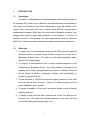
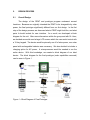
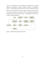
The design of the PEMT and prototype program underwent several
iterations. Because we originally intended the PEMT to be chargeable by solar
power, the final prototype significantly differed from our first design. In the first
step of the design process, we discussed what a PEMT might look like, and what
parts it should include for user interface. As a result, we developed a block
diagram for the unit. After some discussions within the group and with Dr. Hare,
we decided we would need a large LCD screen which the user would control with
a 12-key keypad. The device would be primarily run off of solar power, so a solar
panel with rechargeable batteries was necessary. We also decided to include a
charging option for AC power. A microprocessor would be needed to run the
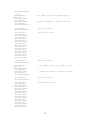
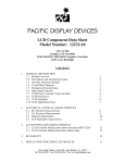
entire device. With this knowledge, we created a block diagram of our ideal
device. The block diagram for the final prototype (solar capabilities removed)
can be seen in Figure 1.
Figure 1 – Block Diagram of Final Prototype
13
2.2
Hardware Design
The next step was selection of the major parts, with a large focus on
reducing cost while maintaining proper functionality. The 128x128 graphic LCD
screen we chose was the Varitronix VL-FS-MGLS128128-31C. This screen was
chosen mainly for its large 2.75 in2 viewing area, which makes it easily readable
for small children.
We chose the All Electronics KP-28, as it was the least
expensive 12-key keypad that we could find.
Instruments
We decided to use a Texas
MSP430 microprocessor because of
its
very
low current
requirement.
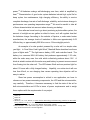
We next designed the power configuration for the device. Our selected
LCD screen required a power supply line of 5V, and a logic drive voltage line of 15V. The MSP430 required a power supply line of 3.3V. To generate these
voltages, we first had to choose the type of rechargeable batteries we would use.
Since we were able to find a microprocessor that consumes less than 1mA of
current, and an LCD module that consumes less than 14mA of current, the team
determined that two series-wired AA batteries would be adequate. This would
produce a nominal voltage of 2.4V, which would be capable of generating the
necessary power lines with boost circuitry while having adequate current capacity
to run the device for a long time.
After researching rechargeable battery
chemistries, NiCd batteries were chosen because they were found to be the most
rugged battery available. This is important for a harsh environment and sporadic
charging and discharging. After researching the possibilities, the NCD1000AA
NiCd batteries, which feature a 1000mAh capacity, were found and ordered form
Zbattery.com.
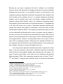
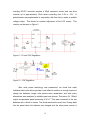
The next step was choosing appropriate boost regulators to produce 5V
and -15V lines. Several switching power supplies were considered, but the final
choice was Maxim’s MAX8569A for the 5V line. This chip only takes 7µA of
supply current and produces a 5V output capable of providing up to 50mA. The
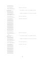
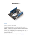
3.3V line was created through linear regulation off of the 5V line.
This was
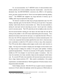
achieved with Microchip’s MCP1700-3302, as can be seen in Figure 2. For the 15V line to bias the LCD, Linear Technology’s LT1617 was chosen. This
14
inverting DC-DC converter requires a 20µA quiescent current and can drive
currents up to approximately 10mA when converting from 2.4V to -15V.
A
potentiometer was implemented in conjunction with this chip to create a variable
voltage output. This allows for contrast adjustment of the LCD screen. This
circuitry can be seen in Figure 3.
Figure 2 – 5V and 3.3V Regulation
Figure 3 – -15V Regulation
After solar power technology was researched, we found that small
individual solar cells did not provide a cost-effective solution or enough current to
charge the batteries. Larger solar panels were researched, and after many
alternatives were analyzed, a suitable panel was chosen. This was a 4V, 100mA
output encapsulated panel measuring 2.36 in2. This was connected to the two
batteries with a diode in series. The diode prevented current from flowing back
into the panel when the batteries are charged and the solar power source is
15
removed.
The largest change to our design occured in February after the
Collaboratory’s Education Group returned from a trip to Mahadaga. Matt Walsh,
a full-time engineer and missionary in Mahadaga, reported that Mahadaga has
gained greater access to electricity in the past year through the implementation
of additional solar arrays. The Mahadaga Handicap Center now has a charging
station with 220V outlets in separate shelves. Since a solar panel adds cost to
the devices, Matt Walsh and the trip team decided that the solar panel is no
longer necessary. As a result, our final design allows for battery charging solely
through an AC-DC power supply.
The alternating current (AC) to direct current (DC) power supply was also
designed with a transformer that stepped the input down from 220Vrms to
12Vrms. The AC waveform was changed to DC through full-wave rectification. A
3.9V Zener diode and a large capacitor were placed across the output in order to
provide a 3.9V output with an acceptable amount of ripple. The output was
designed to provide 100mA of current. This design was not implemented in the
final device.
After taking the high cost of a 220Vrms transformer into
consideration, along with the complexity of creating a durable housing and
connector, it was found that simply purchasing a standard AC-DC power supply
would be more cost effective. We found the T41-9-500D-3 power supply that
outputs 500mA at 9V. It was later determined that we may need to find a power
supply with more current capability.
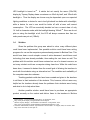
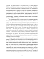
A simple charge controller needed to be implemented in order to prevent
damage to the batteries from overcharging. Due to the charging characteristics of
the NiCd batteries, the battery voltage begins to decrease after full charge has
been reached. Because of this, peak detection circuitry can be used to sense
when this occurs and turn off the solar charging. This was originally designed
with analog components, but after a discussion with Black & Decker engineer
Danny Brotto, this analog circuitry was abandoned for a digital solution. Since our
chosen microprocessor has an unused A to D pin, by connecting the battery
output directly to this pin and recording the voltage level every 30 seconds, we
can sense when the peak voltage level occurs. A resistor divider network was
16
used to ensure the input battery voltage was in a suitable voltage range for the
MSP430.
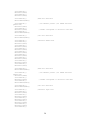
Another microprocessor output pin was utilized to connect and
disconnect the solar panels from the batteries when necessary. An MC7805 was
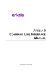
used to regulate the output of the AC to DC power supply to 5V. The two 1Ω
resistors limit the charging current to 500mA. The charging circuitry can be seen
in Figure 4.
Figure 4 – Charging Circuitry
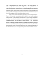
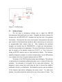
The design of the turn-on and turn-off sequence also became challenging.
The 3.3V must always remain on to allow the microprocessor to control the
battery charging circuitry. The 5V line to the LCD must always be turned on
before the -15V line, and it was found after discussions with Ralph Sabroff, a
Varitronix applications engineer, the 5V line must be turned off after or at the
exact same time as the -15V line. In order to accomplish this, we connected a
double pole, single throw (DPST) switch to both the 5V line leading to the LCD
and the -15V line leading to the LCD. We also allowed one MSP430 input pin to
sense when this 5V line was active, and connected an output pin to a chip enable
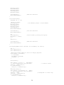
on the -15V regulator. When the switch is thrown on, both the 5V lines and the 15V lines to the LCD are active, but only the 5V line is supplying power. The
MSP430 senses this high voltage, and turns on the -15V chip enable after a short
delay. When the switch is thrown off, both the 5V line and the -15V line are
turned off immediately. The MSP430 the senses the low voltage on the 5V line
and turns off the -15V chip enable to prepare for the next power on sequence.
This design can be seen in Figure 5.
17
Figure 5 – On/Off circuitry
2.3
Software Design
The first step in developing software was to select the MSP430
microprocessor that would meet our needs. Originally, we chose to design the
program with the MSP430FG1617, because this chip had one of the greatest
functionality. We knew that this was a much greater microprocessor than what
was needed, but we decided that we did not want to risk running out of port pins
or programmable flash memory early on.
After completing the prototype
program, we decided that the MSP430F2274, a lower cost microprocessor,
would be more suitable for the application. One event that influence this decision
was the donation of an emulator device, an eZ430-RF, by Texas Instruments
during a MSP430 seminar that our team attended in March.
This emulator,
specially designed to program our chosen microprocessor, has a USB interface
to a computer and a 9-pin connector interface with the PEMT.
The design of the PEMT sample program was challenging. The goal was
to help students conceptualize mathematics rather than to simply drill them with
problems.
We attempted to accomplish this by using word problems.
We
designed a menu screen that would allow the user to choose from addition,
subtraction, division, or multiplication. We decided to give the user ten problems
of the selected type before redisplaying the menu screen.
For each word
problem, the problem would be written at the top of the screen in French. The
18
middle of the screen would then display the problem graphically in a way that
visually reinforces the arithmetic concept. For addition, we designed people to
display on the LCD. We asked how many total people would be at the market, if
there were a certain number of people already at the market, and another
quantity of people joined them. For subtraction, we asked how many ladybugs
would remain if a certain number flew away. We displayed the ladybugs on the
screen and represented the ones that had flown away with large X’s.
For
division, we asked the user how many fish would be in each basket if we divided
them equally between a certain number of baskets. On the screen, fish were
displayed directly above the baskets to show how many fish would be in each.
For multiplication, we asked the total number of ladybugs if there were a set
number of sticks and a certain number of ladybugs on each stick. Once again,
ladybugs were displayed directly above the sticks on the LCD screen so the user
could easily see the total number of ladybugs for each situation. The user would
receive feedback from the LCD after inputting an answer, telling if the problem
was answered correctly. We decided to allow the user to input three incorrect
answers before providing the correct answer and moving to the next problem. A
statistics screen would be displayed that showed the number of problems
answered correctly and the number of tries.
The program was written in C-code using IAR’s Embedded Workbench.
The overall program flow chart can be seen in Figure 6. This program was
designed with four C files. The ProblemSelectorMainAlt.c file is the main file that
runs the high level program operation. This file initializes the LCD, as well as
contains the interrupt for the on/off power switching method described above.
The ProblemSelectorAlt.c file handles the detailed program operation.
responsible for randomly generating the numbers for each problem.
It is
This is
currently performed by performing an algorithm on the input to the A to D
converter. This file calls the LCDControl.c file in order to display the problem
screens. It also calls the Input.c file to get user input, and it handles this user
input, checking the accuracy of the user’s answers. It is also responsible for
displaying the menu screen, calculating statistics, and displaying the statistics
19
screen. The LCDControl.c file is responsible for initializing the LCD, creating
graphics, and displaying the addition, subtraction, division, and multiplication
screens. It also handles any commands written to the LCD, and performs status
checks to ensure that the LCD screen is ready to handle data and commands.
The Input.c file captures any input from the user through the keypad, and
transforms this input into the correct integer. The complete contents of each Cfile can be viewed in Appendix E.
Figure 6 – PEMT Prototype Program Flow Chart
20
3.
IMPLEMENTATION
3.1
Construction
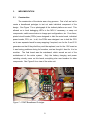
The construction of the device was a long process. First of all, we had to
create a breadboard prototype to test out each individual component of the
design. See Figure 7 for a photograph of the testbed platform we used. This
allowed us to hook debugging LED’s to the MCU if necessary, or swap out
components, switch around wires to change port configurations, etc. From there,
printed circuit boards (PCB’s) were designed to hold the main board, individual
power boards, CPU, etc. In all, four PCB’s were designed: one to hold the CPU
on its own separate board for easy swapping if required, one for the 5 and 3.3V
generators so that if they died they could be replaced, one for the -15V board as
it was having problems during its formation, and we thought it best for it to be
modular.
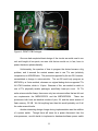
The final board was the mainboard, which served as sort of the
motherboard of the entire system.
Only the battery charging and power
switching circuitry were on this board; everything else was headers for other
components. See Figure 8 for a view of the entire unit.
Figure 7 – PEMT Breadboard Prototype
21
Figure 8– PEMT PCB Prototype
Once we had completed basic design of the circuits we would need in our
unit and bought all our parts, we were told that we would not, in fact, have to
power the device photovoltaically.
Unfortunately, the question of how to program the device became a big
problem, and it seemed the easiest answer was to use TI’s own (relatively
inexpensive) ez-430USB stick. The protocols supported by the ez-430, however,
necessitated a change in microcontroller. The ez-430 could only program an
MSP430 by a 2-wire method, whereas our original debug device supported TI’s
full JTAG interface, which is 14 pins. Because of this, we needed to switch to
one of TI’s physically smaller packages, specifically lower pin count. Of TI’s
entire microcontroller lineup, there were only two microcontrollers that we felt met
our requirements: the MSP430F2274 and the MSP430F2254.
These two
processors both have an identical number of pins, 38, and the same amount of
flash memory, 32 KB. We felt anything less than this would probably not fit all
the code we would write.
Another interesting design change during implementation was the addition
of a power switch. Though there will never be a power disconnect from the
microprocessor, we did decide to implement a hardware/software power switch
22
that would interrupt power to the LCD’s power lines, and would then turn on or off
the enable line form the -15V supply. This is required because the LCD cannot
have the -15V line on while the 5V line is not on or established. So turning on
the 5V and -15V on at the same time would not be good, since the 5V line would
not necessarily be stable before the -15V. Thus the microcontroller turns on the
enable pin once it detects that the 5V is stable, ensuring safe powerup of the
LCD.
Due to the change in processor, new PCB’s had to be designed and code
had to be changed to fit the new microcontroller. Fortunately, since the ‘final
design’ was on a PCB, not on a breadboard, there
were few wires going
everywhere and enclosing the project became a simple matter of cutting
appropriate-sized holes in a sampled enclosure to fit the parts in the right spots.
This enclosure would not stand up to the environment it would see under actual
operation.
3.2
Operation
The device operated within expected parameters.
We were not able to get the chance to do extensive testing on our finished
product, considering the fact that we were not able to even get the final design
working without the assistance of the debugger.
On powerup, the device will briefly display a welcome screen. It will then
display a selection menu from which the user can select addition, subtraction,
division, and multiplication problems. In each problem set, the user is presented
with a series of 10 problems, which the user must enter the answer for. If the
user gets the problem wrong, it ill let them know and tell them to try again. The
exception to this rule is if the same problem has been repeated three times.
Then it will move on to a separate problem.
Once 10 problems have been
displayed and answered (or not answered, as the case may be, the device will
display a statistics screen that informs the user of their performance, giving the
number of times a problem was presented to them and the number of times they
answer correctly. They may then touch any button to continue back to the main
23
menu, where they may select another problem set. The output LCD screens can
be viewed in Appendix D.
The operation of the power on/power off switch was tested on the original
microprocessor and does in fact work. The microcontroller is able to detect the
power switch and turn on or off the -15V line appropriately. The battery charging
system was implemented in hardware on both the breadboard and PCB
prototypes. However, we never got the chance to test out how it functioned on
the microcontroller. The only system we were able to verify was that the battery
charging circuit did in fact supply the batteries with enough power to charge and
that, once the microcontroller detected the peak, would effectively shut off power
to the batteries, preventing them from being over-charged.
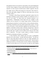
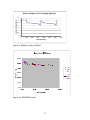
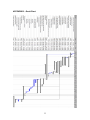
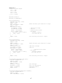
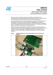
We were able to run some tests on our charge controller and 5V boost
converter, both helping us conclude that we would indeed be able to meet our
run-time specification. As you can see in figures 9 and 10, the battery would be
able to run for 4 hours on a 1-hour charge. This was figured out because we
calculated that the total current draw for the device would be 25 mA. But since
all main power must run through the 5V and 3.3V generator and the converter
has approximately 50% calculated efficiency at 2.4V and 16mA, our total current
consumption would be approximately 50mA. We then set our charging circuit up
to charge for an hour, then discharge at 50mA. When we ran this test, we
discovered that it would run for four hours before the battery charge was at the
level it had been at prior to charging.
24
Battery Voltage Curve for Charging Algorithm
Battery Voltage (Volts)
3.5
3
2.5
2
1.5
1
0.5
0
0
100
200
300
400
Time (minutes)
Figure 9– Battery run time at 50mA
Figure 10– MAX8569 testing
25
500
600
700
4.
PROJECT MANAGEMENT
4.1
Project Organization
Project work was delegated on a weekly basis to the three project team
members, Jeremy Ashinghurst, Scott Eshleman, and Phil Gilde. The work was
divided in equal proportions to all team members and was directed toward team
member’s knowledge and abilities. All team members assisted with design
reports and presentations.
Jeremy Ashinghurst was our team manager and was responsible for
keeping our project binder up to date and managing project deadlines.
He
played a crucial role in selecting an LCD screen. He created the final PCB
layout, built the board, and assembled the final prototype unit. He worked in all
aspects of hardware development.
Scott Eshleman researched solar panels and battery options for the
PEMT. He was responsible for developing and testing the power supply circuitry.
He designed the final LCD screens and wrote all the code that controls the LCD
output.
Phil Gilde was responsible for finding a suitable microprocessor and
selecting a keypad for the device. He wrote all code that handles user input
through the keypad and wrote code for the overall operation of the device. He
was also primarily responsible for developing the charging circuitry.
The project was divided into two semesters. In the fall semester, the team
focused on defining the capabilities of the device, finding suitable components
and creating the necessary circuitry. In the spring semester, the team focused
on developing the software for the prototype program.
building and testing the final PEMT prototype.
26
We also focused on
4.2
Scheduling
For the most part, the original Gantt chart was followed well during the fall
semester. We were able to find and order an LCD screen, solar panel, and
keypad slightly earlier than we anticipated. Unfortunately, there were unforeseen
difficulties in our keypad order, but we were able to obtain the keypads before
December. Our plans for the microprocessor changed slightly. A working
microprocessor was secured, but the final decision on the actual microprocessor
was made in the spring after writing the prototype program. By the milestone
listed, we had a good idea of the type of MSP430 we needed, and samples were
ordered.
In the spring semester, we fell significantly behind our deadlines. This
was due to the largest snag we encountered while working on this project: an
inability to display characters and graphics on the LCD screen followed by an
inability to control the LCD display.
It took nearly two months longer than
expected to be able to fully control the LCD. The main problem was the need to
perform a status check after the command to turn on the display. As a result, our
program was not completed until much later and some testing was condensed.
The following are actual completion times of important milestones. A condensed
version of the original Gantt chart can be viewed in Appendix B.
Milestones
•
Project proposal completed
10/01/07
•
LCD screen ordered
10/10/07
•
Solar panels ordered
10/10/07
•
Input keyboard ordered
10/17/07
•
Microprocessor sampled
10/29/07
•
Microprocessor circuit designed
11/07/07
•
First Power supply designed
11/07/07
•
Complete circuitry bread boarded and tested
11/26/07
•
Final desired program specified
12/01/07
•
EDR presented
12/07/07
27
•
Complete program flow chart created
01/09/08
•
Discuss information learned from January trip
02/07/08
•
Working LCD output
03/24/08
•
Final program finished
04/19/08
•
Components soldered onto milled PCB
04/25/08
•
Entire assembly with program tested
04/30/08
•
Charging circuitry testing performed
05/01/08
•
Final design presentation presented
05/02/08
28
5.
BUDGET
There is a slight difference between our prototype costs and our
production costs. Noting that our production costs were based on 30 units, it is
not surprising that the difference is not greater. This is also due to the fact that
most of the very expensive items did not have a price break at the higher order
numbers. Therefore, our final prototype cost was $101.93 and our final
production cost was $96.20. Not included in the budget breakdown were the gifts
in kind. This included an emulator from Texas Instruments with a part number of
EZ430-RF2500. See Appendix C for Budget.
29
6.
CONCLUSIONS
We did not meet all of our objectives, though we did accomplish the most
important ones. We had six main objectives; we accomplished numbers 1, 2,
and 3 which dealt primarily with the basic functionality of the device as a learning
tool. To this end we have met our objectives. Some of the finer objectives,
however, such as weather resistance and unit cost, however, were unable to be
reached this time. Another of our initial objectives, to have photovoltaic charging,
was deemed unnecessary mid-project.
In light of our objectives, the project was a functional success, with some
work left to be done by subsequent teams.
We have learned a great deal about integrating hardware together while
writing software for it simultaneously.
Since we ended with a different
microcontroller than we started out with, we have had to rewrite some of our
program code for different ports, while the program code itself was already under
development. Another lesson we’ve learned is to always know everything about
all of your components. Most of our spring semester time was spent trying to
figure out how to get the LCD to display data; if we would had a thorough
datasheet, our problems would have been fewer.
30
7.
FUTURE WORK
This project leaves a substantial amount to be done in terms of future
work. The software we created is a good sample of what the device can do, but
in actuality we would like it to have greater functionality.
We have not
incorporated the ability to field-program the device from the device itself.
Currently, writing a program to the device requires a computer to be hooked up
to it, with the TI programming software running.
The future team must also perfect the battery charging circuitry. While we
completed working circuitry and tested this circuitry, the test code was separate
from the final PEMT code. The next team will have to incorporate the charging
code into the main program, placing the microprocessor in its low-power
shutdown mode when it is not taking samples. We also have a software issue in
which lines of code occasionally randomly fail to write in their correct spots. We
believe that sometimes the address pointer resets itself to the home address, but
we were unable to determine when and why this happens. Usually refreshing the
screen corrects the problem.
While the project was, in fact, a success in the sense that we made a
working product, the product that we made will by no means stand up to the
harsh Burkinabe environment.
The casing does not incorporate any sort of
weather-proof seals, for one, and is not custom-formed to the holes needed for
the enclosure. A custom enclosure would be ideal, since it would be able to
make it as small as possible while still fitting everything.
Overall, while there is a good amount of work to be done to bring it to full
functionality, it does work in its current form. Eventually, the Education Group
would like to make a PEMT that could be used by blind children. This would
involve creating brail labels, and incorporating sound and/or vibration into the
PEMT. Since the microprocessor we used does have a few leftover port pins,
this should not be exceedingly difficult to implement. The majority of the future
work will lie in perfecting the prototype to put it into a producible form, followed by
building the thirty desired units.
31
APPENDIX A – REFERENCES
8-Digit LCD Dual-Powered Pocket Calculator. Radio Shack. 30 Sept. 2007.
<http://www.radioshack.com/product/index.jsp?productId=2131033&cp>
BBC. “Snapdragon – How Many?” 25 September 2007.
<http://www.bbc.co.uk/wales/snapdragon/yesflash/how-many-1.htm>
Brain, Marshall. “How Solar Yard Lights Work” HowStuffWorks.com. 30 Sept.
2007. <http://home.howstuffworks.com/solar-light.htm>
Casio USA. “Casio USA Main page.” 25 September 2007.
<http://www.casio.com/home>
Cole-Parmer. “Cole-Parmer Main page.” 25 September 2007.
<http://www.coleparmer.com/index.asp?index=home>
FX-260Solar. Casio. 30 Sept. 2007.
<http://www.casio.com/products/Calculators_%26_Dictionaries/Scientific_
%26_Financial/FX-260Solar/>
Jeff Tyson. “How LCD’s Work.” HowStuffWorks.com. 25 September, 2007.
<http://electronics.howstuffworks.com/lcd2.htm>
Pacfic Display. “LCD Component Data Sheet.” 26 September, 2007.
<http://www.pacificdisplay.com/gdm/GDM-128128-00.pdf>
Roberts, Simon. Solar Electricity: A Practical Guide to Designing and Installing
Small Photovoltaic Systems. Cambridge: Prentice Hall, 1991.
Sharp Corporation. “Sharp Corporation Main page.” 25 September 2007.
<http://www.sharpusa.com/>
Shenzen Topway Display. “LCD Module User Manual.” 26 September, 2007.
<http://www.topwaydisplay.com/Pub/Manual/LM1095E-ManualRev0.1.pdf>
Solar Energy International. Photovoltaics: Design and Installation Manual.
Gabriola Island: New Society Publishers, 2004.
Texas Instruments. “MSP430xG461x Mixed Signal Microcontroller.” 30
November, 2007. <http://focus.ti.com/lit/ds/symlink/msp430fg4619.pdf>
Texas Instruments. “TI Education Main page.” 25 September 2007.
<http://education.ti.com/educationportal/sites/US/homePage/index.html>
TI-36X Solar. Texas Instruments. 30 Sept. 2007.
<http://education.ti.com/educationportal/sites/US/productDetail/us_ti36x_s
olar.html>
32
APPENDIX B – Gantt Chart
33
APPENDIX C – Budget
34
APPENDIX D – Screen Operations
Welcome
Menu
Addition
Subtraction
Multiplication
Division
35
Correct Answer
Maximum Tries Exceeded
Incorrect Answer
Statistics
36
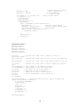
APPENDIX E
ProblemSelectorMainAlt.c
#include "ProblemSelectorAlt.c"
#include "intrinsics.h"
#include "io430xG46x.h"
#pragma vector = PORT1_VECTOR
__raw __interrupt void powerSwitch(){
//Pin 1.0 = 5V sense switch
//Pin 1.2 = -15V enable
unsigned int i =50000;
while(i!=0){
i--;
}
__bic_SR_register(__SR_GIE);
if((P1IN & 0x01) == 0x00){
P1OUT &= 0xfb;
terminate = 1;
P1IES = 0x00;
}
else{
P1OUT |= 0x04;
terminate = 0;
P1IES = 0x01;
}
P1IFG = 0x00;
__bis_SR_register(__SR_GIE);
//short delay for switch debounce
//and -15V supply delay (50ms min)
//Disable Global Interrupt
//If Power turned off
//Disable -15V
//Power turned on
//Enable -15V
//Clear interrupt flag
//Enable Global Interrupt
}
void main(){
int theAnswer;
// Stop watchdog timer to prevent time out reset
WDTCTL = WDTPW + WDTHOLD;
terminate = 1;
//load program with power switch off
P1DIR &= 0xfe;
P1DIR |= 0x04;
P1OUT &= 0xfb;
//Disable -15V
P1IES = 0x00;
//Interrupt to occur on rising edge
P1IE = 0x01;
//Enable interrupt on Pin 1.0
__bis_SR_register(__SR_GIE); //Enable Global Interrupt
while(1){
P10OUT &= 0x00;
// Set this pin to off
P10DIR |= 0x01;
// Enable shut-off pin for
batteries
ADC12CTL0 &= 0xfffd;
// Disable conversions
P6SEL |= 0x01;
// Enable A/D channel A0
P6DIR &= 0xfe;
ADC12CTL0 = REFON + REF2_5V + ADC12ON + SHT0_2 + MSC;
// turn on 2.5V ref, set samp
time
ADC12CTL1 = SHP + CONSEQ_2 + CSTARTADD_0;
// Use sampling
timer and set mode
ADC12MCTL0 = SREF_1;
// Vr+=Vref+
for (int i = 0x3600; i; i--);
start-up.
// Delay for needed ref
37
// See datasheet for details.
// Enable conversions
// Start conversions
// Conversion done?
// Delay for next result
ADC12CTL0 |= ENC;
ADC12CTL0 |= ADC12SC;
for (double x = 0; x <1000; x++);
if (terminate == 0){
InitializeLCD();
initializeVar();
while(terminate == 0){
displayMenu();
while ((problemNum <=10)&&(terminate==0)){
generateNums();
//Generate random numbers
theAnswer = getUserInput();
//Display problem and get answer
checkAnswer(theAnswer);
//Check answer
while ((count > 0)&&(terminate==0)){
checkAnswer(answer);
}
}
displayStats();
clearStats();
}
}
}
}
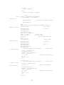
ProblemSelectorAlt.c
#include <math.h>
#include "Input.c"
#include <string.h>
#include "LCDControl.c"
#include "stdio.h"
#include "stdlib.h"
int count;
/* Variable that keeps track of number of tries on a
particular problem */
int totalTries; /* Variable that keeps track of total tries in the problem set
*/
int problemNum; /* Variable that keeps track of the problem number in the set
*/
int correct;
/* Variable that keeps track of correct answers per problem
set */
int firstNumber; /* First number in the addition problem */
int secondNumber;/* Second number in the addition problem */
int answer;
/* The answer for any given problem */
int option;
/* Selection for type of problem */
int result;
/* Answer user input is checked against */
int key;
/* Value corresponding to the pressed key */
int time;
int terminate;
void initializeVar(){ /* Method that initializes all global variables and
ensures random number generation */
int voltage = ADC12MEM0;
srand(voltage);
count = 0;
problemNum = 1;
correct = 0;
totalTries = 0;
firstNumber = 0;
secondNumber = 0;
}
void displayMenu(){
38
ClearScreen();
char line1[] = "Priere de choisir";
line1[3] = 0x8a;
//Corresponds to accent grave
PrintLine(line1,0);
PrintLine("de ce menu une",1);
char line2[] = "categorie de probleme";
line2[3] = 0x82;
//Corresponds to accent aigu
line2[18] = 0x8a;
PrintLine(line2,2);
PrintLine(" 1. Addition",4);
PrintLine(" 2. Soustraction",5);
PrintLine(" 4. Multiplication",7);
PrintLine(" 3. Division",6);
PrintLine("Choix: ",10);
StatusCheck1();
WriteData(0x07);
StatusCheck1();
WriteData(0x0a);
StatusCheck1();
WriteCommand(0x21);
StatusCheck1();
WriteCommand(0x97);
StatusCheck1();
//Set cursor pointer address
//column 7
//row 10
//Turn cursor on
option = getKey();
StatusCheck1();
WriteData(0xd9);
StatusCheck1();
WriteData(0x00);
StatusCheck1();
WriteCommand(0x24);
//Set pointer address
//to cursor position
//10*21+7 = 217
StatusCheck1();
WriteData(option+0x10);
StatusCheck1();
WriteCommand(0xc0);
//display obtained number
unsigned int i = 20000;
do i--;
while (i!=0);
}
//delay for viewing
void generateNums(){
firstNumber = (int)((floor(rand()*21.0))/32767.0); /* Generates random
number between 0-20 */
secondNumber = (int)((floor(rand()*21.0))/32767.0); /* Generates random
number between 0-20 */
/*Write code to display these two numbers on the screen in an addition
problem */
}
int getUserInput(){
int i=0;
int j;
string conversion
int input;
char numberStr1[2];
string conversion
//dummy variable for decimal to
//data input from user
//Number array for decimal to
39
char numberStr2[1];
int number1,number2;
StatusCheck1();
WriteCommand(0x97);
//Turn On Cursor
StatusCheck1();
switch (option){
case 1: result = firstNumber + secondNumber;
*
addition */
if (result > 20) {
/* Account for results
greater than 20. Regenerate numbers */
generateNums();
getUserInput();
}
else {
DisplayAddition(firstNumber,secondNumber,result);
WriteData(0x2f);
//Set pointer address to cursor
location
StatusCheck1();
WriteData(0x01);
StatusCheck1();
WriteCommand(0x24);
char line[] = "Reponse:
";
line[1] = 0x82;
//accent aigu
input = getKey();
//Get user input
j = 20000;
//delay before next input
do j--;
while (j!=0);
StatusCheck1();
//Reset cursor
pointer address
WriteData(0x0a);
//column 10
StatusCheck1();
WriteData(0x0e);
//row 14
StatusCheck1();
WriteCommand(0x21);
if(input!=10){
j = sprintf(numberStr1,"%d",input);
//convert input
to number string
line[9] = numberStr1[0];
PrintLine(line,14);
number1 = atoi(numberStr1);
input = getKey();
j = 20000;
//delay before next input
do j--;
while (j!=0);
i++;
}
if(input!=10){
j = sprintf(numberStr2,"%d",input);
//convert input
to number string
line[10] = numberStr2[0];
line[0]= 'R';
//Reset R (Disappears,
Reason Unknown)
PrintLine(line,14);
number2 = atoi(numberStr2);
input = getKey();
j = 20000;
//delay before next input
do j--;
while (j!=0);
i++;
}
if(i==0){
answer = 0;
}
40
if(i==1){
answer = number1;
}
else{
answer = 10*number1 + number2;
}
}
break;
case 2: result = firstNumber-secondNumber;
if (secondNumber > firstNumber) {
/*
subtraction */
generateNums();
/* Account for negative numbers
*/
getUserInput();
}
else {
DisplaySubtraction(firstNumber,secondNumber,result);
WriteData(0x18);
//Set pointer
address to cursor
StatusCheck1();
//location
WriteData(0x01);
StatusCheck1();
WriteCommand(0x24);
char line[] = "Reponse:
";
line[1] = 0x82;
//accent aigu
input = getKey();
//Get user input
j = 20000;
//delay before next input
do j--;
while (j!=0);
StatusCheck1();
//Reset cursor
pointer address
WriteData(0x0a);
//column 10
StatusCheck1();
WriteData(0x0d);
//row 13
StatusCheck1();
WriteCommand(0x21);
if(input!=10){
j = sprintf(numberStr1,"%d",input);
//convert input
to number string
line[9] = numberStr1[0];
PrintLine(line,13);
number1 = atoi(numberStr1);
input = getKey();
j = 20000;
//delay before next input
do j--;
while (j!=0);
i++;
}
if(input!=10){
j = sprintf(numberStr2,"%d",input);
//convert input
to number string
line[10] = numberStr2[0];
line[0]= 'R';
//Reset R (Disappears,
Reason Unknown)
PrintLine(line,13);
number2 = atoi(numberStr2);
input = getKey();
j = 20000;
//delay before next input
do j--;
while (j!=0);
i++;
}
if(i==0){
41
answer = 0;
}
if(i==1){
answer = number1;
}
else{
answer = 10*number1 + number2;
}
}
break;
case 3: result = firstNumber/secondNumber;
if (secondNumber > firstNumber || secondNumber == 0 ||
firstNumber%secondNumber != 0 || result > 10){ // division
generateNums();
/* Account for
results of 0 or non-integer results */
getUserInput();
}
else {
DisplayDiv(firstNumber,secondNumber,result);
WriteData(0x32);
//Set pointer
address to cursor
StatusCheck1();
//location
WriteData(0x01);
StatusCheck1();
WriteCommand(0x24);
char line[] = "Reponse:
";
line[1] = 0x82;
//accent aigu
input = getKey();
//Get user input
j = 20000;
//delay before next input
do j--;
while (j!=0);
StatusCheck1();
//Reset cursor
pointer address
WriteData(0x0a);
//column 10
StatusCheck1();
WriteData(0x0f);
//row 15
StatusCheck1();
WriteCommand(0x21);
if(input!=10){
j = sprintf(numberStr1,"%d",input);
//convert input
to number string
line[9] = numberStr1[0];
PrintLine(line,15);
number1 = atoi(numberStr1);
input = getKey();
j = 20000;
//delay before next input
do j--;
while (j!=0);
i++;
}
if(input!=10){
j = sprintf(numberStr2,"%d",input);
//convert input
to number string
line[10] = numberStr2[0];
line[0]= 'R';
//Reset R (Disappears,
Reason Unknown)
PrintLine(line,15);
number2 = atoi(numberStr2);
input = getKey();
j = 20000;
//delay before next input
do j--;
while (j!=0);
i++;
42
}
if(i==0){
answer = 0;
}
if(i==1){
answer = number1;
}
else{
answer = 10*number1 + number2;
}
}
break;
case 4: result = firstNumber * secondNumber;
/* multiplication */
if (result > 20 || result == 0) {
/*Account for
results greater than 20 */
generateNums();
getUserInput();
}
else {
DisplayMult(firstNumber,secondNumber,result);
WriteData(0x32);
//Set pointer
address to cursor
StatusCheck1();
//location
WriteData(0x01);
StatusCheck1();
WriteCommand(0x24);
char line[] = "Reponse:
";
line[1] = 0x82;
//accent aigu
input = getKey();
//Get user input
j = 20000;
//delay before next input
do j--;
while (j!=0);
StatusCheck1();
//Reset cursor
pointer address
WriteData(0x0a);
//column 10
StatusCheck1();
WriteData(0x0f);
//row 15
StatusCheck1();
WriteCommand(0x21);
if(input!=10){
j = sprintf(numberStr1,"%d",input);
//convert input
to number string
line[9] = numberStr1[0];
PrintLine(line,15);
number1 = atoi(numberStr1);
input = getKey();
j = 20000;
//delay before next input
do j--;
while (j!=0);
i++;
}
if(input!=10){
j = sprintf(numberStr2,"%d",input);
//convert input
to number string
line[10] = numberStr2[0];
line[0]= 'R';
//Reset R (Disappears,
Reason Unknown)
PrintLine(line,15);
number2 = atoi(numberStr2);
input = getKey();
j = 20000;
//delay before next input
do j--;
43
while (j!=0);
i++;
}
if(i==0){
answer = 0;
}
if(i==1){
answer = number1;
}
else{
answer = 10*number1 + number2;
}
}
break;
}
return answer;
}
int checkAnswer(int answer){
int j;
char numberStr[2];
ClearScreen();
if ((count >= 2) & (answer!=result)){
/* Max tries
condition exceeded condition */
problemNum++;
totalTries++;
count = 0;
PrintLine("Tentatives maximums",1);
char line1[] = " excedees!";
line1[5] = 0x82;
line1[7] = 0x82;
PrintLine(line1,2);
char line2[]= "La reponse correcte";
line2[4] = 0x82;
PrintLine(line2,4);
char line3[] = " est
.";
j = sprintf(numberStr,"%d",result);
//j doesn't matter
line3[6] = numberStr[0];
if (result>=10){
line3[7] = numberStr[1];
}
line3[0] = ' ';
//Disappears (Reason Unknown)
PrintLine(line3,5);
PrintLine("Appuyez sur n'importe", 13);
PrintLine("quelle touche pour", 14);
PrintLine("continuer.", 15);
StatusCheck1();
WriteCommand(0x94);
//Turn Off Cursor
StatusCheck1();
getKey();
return 0;
}
else if (answer == result){
/* Correct answer condition */
totalTries++;
correct++;
count = 0;
problemNum++;
PrintLine("Correct!",5);
char line[] = "Tres bien!";
line[2] = 0x8a;
PrintLine(line,6);
PrintLine("Appuyez sur n'importe", 13);
PrintLine("quelle touche pour", 14);
PrintLine("continuer.", 15);
44
StatusCheck1();
WriteCommand(0x94);
//Turn Off Cursor
StatusCheck1();
getKey();
return 1;
}
else{
/* Incorrect answer condition */
totalTries++;
count++;
PrintLine("Incorrect.",5);
PrintLine("Essayez de nouveau.",7);
PrintLine("Appuyez sur n'importe", 13);
PrintLine("quelle touche pour", 14);
PrintLine("continuer.", 15);
StatusCheck1();
WriteCommand(0x94);
//Turn Off Cursor
StatusCheck1();
getKey();
return getUserInput();
}
}
void displayStats(){
char numberStr1[2];
char numberStr2[2];
int j;
ClearScreen();
StatusCheck1();
WriteCommand(0x94);
//Turn Off Cursor
StatusCheck1();
PrintLine("Statistiques",1);
PrintLine("Nombre de tentatives:",3);
j = sprintf(numberStr1,"%d",totalTries);
//j doesn't matter
PrintLine(numberStr1,4);
PrintLine("Nombre correct:",6);
j = sprintf(numberStr2,"%d",correct);
//j doesn't matter
PrintLine(numberStr2,7);
PrintLine("Appuyez sur n'importe", 13);
PrintLine("quelle touche pour", 14);
PrintLine("continuer.", 15);
getKey();
}
void clearStats(){
count = 0;
problemNum = 1;
correct = 0;
totalTries = 0;
firstNumber = 0;
secondNumber = 0;
}
Input.c
#include "math.h"
#include "io430xG46x.h"
int getNumberPressed(int address){
decimal value to determine the number pressed on the keypad
int x = -1;
//returns cancel if there is some kind of error
switch(address){
case 9: x=1;
break;
45
//uses
case 10: x=2;
break;
case 12: x=3;
break;
case 17: x=4;
break;
case 18: x=5;
break;
case 20: x=6;
break;
case 33: x=7;
break;
case 34: x=8;
break;
case 36: x=9;
break;
case 65: x=-1;
break;
case 66: x=0;
break;
case 68: x=10;
break;
}
return x;
}
int getKey(){
int option;
P2DIR = 0x07;
//set first 3 keypad pins as outputs
do{
option = 0;
unsigned char read = 0x00;
P2OUT = 0x01;
read = P2IN & 0x78;
if(read != 0){
//checks to see if key pressed is in
first column
option = 1;
return getNumberPressed(P2IN);
}
else{
P2OUT = 0x02;
read = P2IN & 0x78;
if (read != 0){
//checks to see if key pressed is in
second column
option = 1;
//if yes passes value of P1IN to NumberSelection
return getNumberPressed(P2IN);
}
else{
P2OUT = 0x04;
read = P2IN & 0x78;
if (read != 0){
//checks to see if key pressed is in
third column
option = 1;
//if yes passes value of P1IN to NumberSelection
return getNumberPressed(P2IN);
}
}
}
//
if((P1IN & 0x01) == 0x00){
//Exit loop for machine turnoff
//
option = 1;
//
}
}//end do
while(option == 0);
}
46
LCDControl.c
/* Port 4 is Data Output
P3.0 = !WR
P3.1 = !RD
P3.2 = !CE
P3.3 = C/!D
P3.4 = !Reset
*/
#include "stdio.h"
#include "io430xG46x.h"
void StatusCheck1(){
unsigned char busy = 0x00;
P3DIR &= 0xe0;
P4DIR = 0x00;
char statusCheck = P3IN;
P3DIR |= 0x1f;
while(busy != 0x03){
statusCheck |=0x09;
statusCheck &= 0xfd;
P3OUT = statusCheck;
busy = (P4IN & 0x03);
//
if((P1IN & 0x01) == 0x00){
//
busy = 0x03;
//
}
}
P4DIR = 0xff;
}
void StatusCheck2(){
unsigned char busy = 0x00;
P3DIR &= 0xe0;
P4DIR = 0x00;
char statusCheck = P3IN;
P3DIR |= 0x1f;
statusCheck |=0x09;
statusCheck &= 0xfd;
while(busy != 0x08){
P3OUT = statusCheck;
busy = (P4IN & 0x08);
//
if((P1IN & 0x01) == 0x00){
//
busy = 0x03;
//
}
}
P4DIR = 0xff;
}
//Reset LCD data port direction to input
//!WR and C/!D high
//!RD low
//Perform status check
//Get busy!
//Timeout function
//for LCD turn off
//Set LCD data port back to output
//Reset LCD data port direction to input
//!WR and C/!D high
//!RD low
//Perform status check
//Get busy!
//Timeout function
//for LCD turn off
//Set LCD data port back to output
void WriteData(unsigned char data){
volatile unsigned int i;
P3DIR &= 0xe0;
char dataWrite = P3IN;
P3DIR |= 0x1f;
dataWrite |= 0x02;
//Set !RD high
dataWrite &= 0xf6;
//Set C/!D and !WR Low
P3OUT = dataWrite;
//Send LCD Control
P4OUT = data;
//Send Data
}
void WriteCommand(unsigned char command){
volatile unsigned int i;
P3DIR &= 0xe0;
char commandWrite = P3IN;
47
P3DIR |= 0x1f;
commandWrite |= 0x0a;
commandWrite &= 0xfe;
P3OUT = commandWrite;
P4OUT = command;
//Set
//Set
//Send
//Send
!Rd and C/!D High
!WR Low
LCD Control
Command
}
void PrintLine(char line[], int row){
//row must be in the visible range (0-15)
//line[] is a string consisting of less than 21 characters
int i,j=0;
char highaddress;
if (row<12){
highaddress = 0x00; //Calculate correct pointer address
}
else {
highaddress = 0x01;
}
StatusCheck1();
WriteData(row*21);
StatusCheck1();
WriteData(highaddress);
StatusCheck1();
WriteCommand(0x24);
//Set pointer address
StatusCheck1();
WriteCommand(0xb0);
//Set Data Autowrite mode
StatusCheck1();
for(i=0;line[i]!='\0';i++){
StatusCheck2();
WriteData(line[i]-0x20);
j++;
}
//Print character array one at a time
//LCD character address = ASCII - 0x20
for(i=j;i<21;i++){
StatusCheck2();
WriteData(' '-0x20);
}
//Fill remaining line with spaces
StatusCheck2();
WriteCommand(0xb2);
//End Data Autowrite
}
void GenerateGraphics(){
StatusCheck1();
generation)
WriteData(0x02);
0x1400
StatusCheck1();
WriteData(0x00);
StatusCheck1();
WriteCommand(0x22);
//Person
StatusCheck1();
generation)
WriteData(0x00);
StatusCheck1();
WriteData(0x14);
StatusCheck1();
//Set offset register (for CGROM character
//corresponds to address 00010 1000000 000 =
//Set address pointer (for CGROM character
//0x1400 corresponds to character code 0x80
48
WriteCommand(0x24);
StatusCheck1();
WriteCommand(0xb0);
//Set Data Autowrite
StatusCheck1();
StatusCheck2();
WriteData(0x00);
StatusCheck2();
WriteData(0x03);
StatusCheck2();
WriteData(0x07);
StatusCheck2();
WriteData(0x07);
StatusCheck2();
WriteData(0x07);
StatusCheck2();
WriteData(0x03);
StatusCheck2();
WriteData(0x01);
StatusCheck2();
WriteData(0x03);
//Generate upper left person
StatusCheck2();
WriteCommand(0xb2);
//End Data Autowrite
StatusCheck1();
generation)
WriteData(0x08);
StatusCheck1();
WriteData(0x14);
StatusCheck1();
WriteCommand(0x24);
//Set address pointer (for CGROM character
//0x1408 corresponds to character code 0x81
StatusCheck1();
WriteCommand(0xb0);
//Set Data Autowrite
StatusCheck1();
StatusCheck2();
WriteData(0x00);
StatusCheck2();
WriteData(0x30);
StatusCheck2();
WriteData(0x38);
StatusCheck2();
WriteData(0x38);
StatusCheck2();
WriteData(0x38);
StatusCheck2();
WriteData(0x30);
StatusCheck2();
WriteData(0x20);
StatusCheck2();
WriteData(0x30);
//Generate upper right person
StatusCheck2();
WriteCommand(0xb2);
//End Data Autowrite
StatusCheck1();
generation)
WriteData(0x10);
StatusCheck1();
WriteData(0x14);
//Set address pointer (for CGROM character
//0x1410 corresponds to character code 0x82
49
StatusCheck1();
WriteCommand(0x24);
StatusCheck1();
WriteCommand(0xb0);
//Set Data Autowrite
StatusCheck1();
StatusCheck2();
WriteData(0x05);
StatusCheck2();
WriteData(0x09);
StatusCheck2();
WriteData(0x01);
StatusCheck2();
WriteData(0x01);
StatusCheck2();
WriteData(0x01);
StatusCheck2();
WriteData(0x02);
StatusCheck2();
WriteData(0x0c);
StatusCheck2();
WriteData(0x00);
//Generate lower left person
StatusCheck2();
WriteCommand(0xb2);
//End Data Autowrite
StatusCheck1();
generation)
WriteData(0x18);
StatusCheck1();
WriteData(0x14);
StatusCheck1();
WriteCommand(0x24);
//Set address pointer (for CGROM character
//0x1418 corresponds to character code 0x83
StatusCheck1();
WriteCommand(0xb0);
//Set Data Autowrite
StatusCheck1();
StatusCheck2();
WriteData(0x28);
StatusCheck2();
WriteData(0x24);
StatusCheck2();
WriteData(0x20);
StatusCheck2();
WriteData(0x20);
StatusCheck2();
WriteData(0x20);
StatusCheck2();
WriteData(0x10);
StatusCheck2();
WriteData(0x0c);
StatusCheck2();
WriteData(0x00);
//Generate lower right person
StatusCheck2();
WriteCommand(0xb2);
//End Data Autowrite
//Ladybug
StatusCheck1();
generation)
WriteData(0x20);
//Set address pointer (for CGROM character
50
StatusCheck1();
WriteData(0x14);
StatusCheck1();
WriteCommand(0x24);
//0x1400 corresponds to character code 0x84
StatusCheck1();
WriteCommand(0xb0);
//Set Data Autowrite
StatusCheck1();
StatusCheck2();
WriteData(0x04);
StatusCheck2();
WriteData(0x02);
StatusCheck2();
WriteData(0x01);
StatusCheck2();
WriteData(0x03);
StatusCheck2();
WriteData(0x03);
StatusCheck2();
WriteData(0x04);
StatusCheck2();
WriteData(0x09);
StatusCheck2();
WriteData(0x09);
//Generate upper left ladybug
StatusCheck2();
WriteCommand(0xb2);
//End Data Autowrite
StatusCheck1();
generation)
WriteData(0x28);
StatusCheck1();
WriteData(0x14);
StatusCheck1();
WriteCommand(0x24);
//Set address pointer (for CGROM character
//0x1428 corresponds to character code 0x85
StatusCheck1();
WriteCommand(0xb0);
//Set Data Autowrite
StatusCheck1();
StatusCheck2();
WriteData(0x08);
StatusCheck2();
WriteData(0x10);
StatusCheck2();
WriteData(0x20);
StatusCheck2();
WriteData(0x30);
StatusCheck2();
WriteData(0x30);
StatusCheck2();
WriteData(0x08);
StatusCheck2();
WriteData(0x24);
StatusCheck2();
WriteData(0x24);
//Generate upper right ladybug
StatusCheck2();
WriteCommand(0xb2);
//End Data Autowrite
StatusCheck1();
generation)
//Set address pointer (for CGROM character
51
WriteData(0x30);
StatusCheck1();
WriteData(0x14);
StatusCheck1();
WriteCommand(0x24);
//0x1430 corresponds to character code 0x86
StatusCheck1();
WriteCommand(0xb0);
//Set Data Autowrite
StatusCheck1();
StatusCheck2();
WriteData(0x10);
StatusCheck2();
WriteData(0x16);
StatusCheck2();
WriteData(0x12);
StatusCheck2();
WriteData(0x08);
StatusCheck2();
WriteData(0x09);
StatusCheck2();
WriteData(0x04);
StatusCheck2();
WriteData(0x03);
StatusCheck2();
WriteData(0x00);
//Generate lower left ladybug
StatusCheck2();
WriteCommand(0xb2);
//End Data Autowrite
StatusCheck1();
generation)
WriteData(0x38);
StatusCheck1();
WriteData(0x14);
StatusCheck1();
WriteCommand(0x24);
//Set address pointer (for CGROM character
//0x1438 corresponds to character code 0x87
StatusCheck1();
WriteCommand(0xb0);
//Set Data Autowrite
StatusCheck1();
StatusCheck2();
WriteData(0x02);
StatusCheck2();
WriteData(0x1a);
StatusCheck2();
WriteData(0x12);
StatusCheck2();
WriteData(0x04);
StatusCheck2();
WriteData(0x24);
StatusCheck2();
WriteData(0x08);
StatusCheck2();
WriteData(0x30);
StatusCheck2();
WriteData(0x00);
//Generate lower right ladybug
StatusCheck2();
WriteCommand(0xb2);
//End Data Autowrite
//Generate X
52
StatusCheck1();
generation)
WriteData(0x40);
StatusCheck1();
WriteData(0x14);
StatusCheck1();
WriteCommand(0x24);
//Set address pointer (for CGROM character
//0x1440 corresponds to character code 0x88
StatusCheck1();
WriteCommand(0xb0);
//Set Data Autowrite
StatusCheck1();
StatusCheck2();
WriteData(0x00);
StatusCheck2();
WriteData(0x10);
StatusCheck2();
WriteData(0x10);
StatusCheck2();
WriteData(0x08);
StatusCheck2();
WriteData(0x04);
StatusCheck2();
WriteData(0x04);
StatusCheck2();
WriteData(0x02);
StatusCheck2();
WriteData(0x01);
//Generate upper left X
StatusCheck2();
WriteCommand(0xb2);
//End Data Autowrite
StatusCheck1();
generation)
WriteData(0x48);
StatusCheck1();
WriteData(0x14);
StatusCheck1();
WriteCommand(0x24);
//Set address pointer (for CGROM character
//0x1448 corresponds to character code 0x89
StatusCheck1();
WriteCommand(0xb0);
//Set Data Autowrite
StatusCheck1();
StatusCheck2();
WriteData(0x00);
StatusCheck2();
WriteData(0x02);
StatusCheck2();
WriteData(0x02);
StatusCheck2();
WriteData(0x04);
StatusCheck2();
WriteData(0x08);
StatusCheck2();
WriteData(0x08);
StatusCheck2();
WriteData(0x10);
StatusCheck2();
WriteData(0x20);
//Generate upper right X
StatusCheck2();
WriteCommand(0xb2);
//End Data Autowrite
53
StatusCheck1();
generation)
WriteData(0x50);
StatusCheck1();
WriteData(0x14);
StatusCheck1();
WriteCommand(0x24);
//Set address pointer (for CGROM character
//0x1450 corresponds to character code 0x8a
StatusCheck1();
WriteCommand(0xb0);
//Set Data Autowrite
StatusCheck1();
StatusCheck2();
WriteData(0x01);
StatusCheck2();
WriteData(0x02);
StatusCheck2();
WriteData(0x04);
StatusCheck2();
WriteData(0x04);
StatusCheck2();
WriteData(0x08);
StatusCheck2();
WriteData(0x10);
StatusCheck2();
WriteData(0x10);
StatusCheck2();
WriteData(0x00);
//Generate lower left X
StatusCheck2();
WriteCommand(0xb2);
//End Data Autowrite
StatusCheck1();
generation)
WriteData(0x58);
StatusCheck1();
WriteData(0x14);
StatusCheck1();
WriteCommand(0x24);
//Set address pointer (for CGROM character
//0x1458 corresponds to character code 0x8b
StatusCheck1();
WriteCommand(0xb0);
//Set Data Autowrite
StatusCheck1();
StatusCheck2();
WriteData(0x20);
StatusCheck2();
WriteData(0x10);
StatusCheck2();
WriteData(0x08);
StatusCheck2();
WriteData(0x08);
StatusCheck2();
WriteData(0x04);
StatusCheck2();
WriteData(0x02);
StatusCheck2();
WriteData(0x02);
StatusCheck2();
WriteData(0x00);
//Generate lower right X
StatusCheck2();
//End Data Autowrite
54
WriteCommand(0xb2);
//Stick
StatusCheck1();
generation)
WriteData(0x60);
StatusCheck1();
WriteData(0x14);
StatusCheck1();
WriteCommand(0x24);
//Set address pointer (for CGROM character
//0x1460 corresponds to character code 0x8c
StatusCheck1();
WriteCommand(0xb0);
//Set Data Autowrite
StatusCheck1();
StatusCheck2();
WriteData(0x00);
StatusCheck2();
WriteData(0x10);
StatusCheck2();
WriteData(0x18);
StatusCheck2();
WriteData(0x1f);
StatusCheck2();
WriteData(0x1f);
StatusCheck2();
WriteData(0x18);
StatusCheck2();
WriteData(0x10);
StatusCheck2();
WriteData(0x00);
//Generate left stick
StatusCheck2();
WriteCommand(0xb2);
//End Data Autowrite
StatusCheck1();
generation)
WriteData(0x68);
StatusCheck1();
WriteData(0x14);
StatusCheck1();
WriteCommand(0x24);
//Set address pointer (for CGROM character
//0x1468 corresponds to character code 0x8d
StatusCheck1();
WriteCommand(0xb0);
//Set Data Autowrite
StatusCheck1();
StatusCheck2();
WriteData(0x00);
StatusCheck2();
WriteData(0x02);
StatusCheck2();
WriteData(0x04);
StatusCheck2();
WriteData(0x3f);
StatusCheck2();
WriteData(0x3f);
StatusCheck2();
WriteData(0x20);
StatusCheck2();
WriteData(0x10);
StatusCheck2();
WriteData(0x00);
//Generate middle stick
55
StatusCheck2();
WriteCommand(0xb2);
StatusCheck1();
generation)
WriteData(0x70);
StatusCheck1();
WriteData(0x14);
StatusCheck1();
WriteCommand(0x24);
//End Data Autowrite
//Set address pointer (for CGROM character
//0x1470 corresponds to character code 0x8e
StatusCheck1();
WriteCommand(0xb0);
//Set Data Autowrite
StatusCheck1();
StatusCheck2();
WriteData(0x00);
StatusCheck2();
WriteData(0x00);
StatusCheck2();
WriteData(0x10);
StatusCheck2();
WriteData(0x20);
StatusCheck2();
WriteData(0x3e);
StatusCheck2();
WriteData(0x10);
StatusCheck2();
WriteData(0x08);
StatusCheck2();
WriteData(0x00);
//Generate right stick
StatusCheck2();
WriteCommand(0xb2);
//End Data Autowrite
//Fish
StatusCheck1();
generation)
WriteData(0x78);
StatusCheck1();
WriteData(0x14);
StatusCheck1();
WriteCommand(0x24);
//Set address pointer (for CGROM character
//0x1478 corresponds to character code 0x8f
StatusCheck1();
WriteCommand(0xb0);
//Set Data Autowrite
StatusCheck1();
StatusCheck2();
WriteData(0x00);
StatusCheck2();
WriteData(0x10);
StatusCheck2();
WriteData(0x18);
StatusCheck2();
WriteData(0x1d);
StatusCheck2();
WriteData(0x1f);
StatusCheck2();
WriteData(0x1d);
StatusCheck2();
WriteData(0x18);
//Generate left fish
56
StatusCheck2();
WriteData(0x10);
StatusCheck2();
WriteCommand(0xb2);
StatusCheck1();
generation)
WriteData(0x80);
StatusCheck1();
WriteData(0x14);
StatusCheck1();
WriteCommand(0x24);
//End Data Autowrite
//Set address pointer (for CGROM character
//0x1480 corresponds to character code 0x90
StatusCheck1();
WriteCommand(0xb0);
//Set Data Autowrite
StatusCheck1();
StatusCheck2();
WriteData(0x00);
StatusCheck2();
WriteData(0x1c);
StatusCheck2();
WriteData(0x3e);
StatusCheck2();
WriteData(0x3f);
StatusCheck2();
WriteData(0x3f);
StatusCheck2();
WriteData(0x3f);
StatusCheck2();
WriteData(0x3e);
StatusCheck2();
WriteData(0x1c);
//Generate right fish
StatusCheck2();
WriteCommand(0xb2);
//End Data Autowrite
//Bowl
StatusCheck1();
generation)
WriteData(0x88);
StatusCheck1();
WriteData(0x14);
StatusCheck1();
WriteCommand(0x24);
//Set address pointer (for CGROM character
//0x1488 corresponds to character code 0x91
StatusCheck1();
WriteCommand(0xb0);
//Set Data Autowrite
StatusCheck1();
StatusCheck2();
WriteData(0x00);
StatusCheck2();
WriteData(0x1f);
StatusCheck2();
WriteData(0x0f);
StatusCheck2();
WriteData(0x07);
StatusCheck2();
WriteData(0x03);
StatusCheck2();
WriteData(0x01);
//Generate left bowl
57
StatusCheck2();
WriteData(0x00);
StatusCheck2();
WriteData(0x00);
StatusCheck2();
WriteCommand(0xb2);
StatusCheck1();
generation)
WriteData(0x90);
StatusCheck1();
WriteData(0x14);
StatusCheck1();
WriteCommand(0x24);
//End Data Autowrite
//Set address pointer (for CGROM character
//0x1490 corresponds to character code 0x92
StatusCheck1();
WriteCommand(0xb0);
//Set Data Autowrite
StatusCheck1();
StatusCheck2();
WriteData(0x00);
StatusCheck2();
WriteData(0x3f);
StatusCheck2();
WriteData(0x3f);
StatusCheck2();
WriteData(0x3f);
StatusCheck2();
WriteData(0x00);
StatusCheck2();
WriteData(0x3f);
StatusCheck2();
WriteData(0x3f);
StatusCheck2();
WriteData(0x00);
//Generate middle bowl
StatusCheck2();
WriteCommand(0xb2);
//End Data Autowrite
StatusCheck1();
generation)
WriteData(0x98);
StatusCheck1();
WriteData(0x14);
StatusCheck1();
WriteCommand(0x24);
//Set address pointer (for CGROM character
//0x1498 corresponds to character code 0x93
StatusCheck1();
WriteCommand(0xb0);
//Set Data Autowrite
StatusCheck1();
StatusCheck2();
WriteData(0x00);
StatusCheck2();
WriteData(0x3e);
StatusCheck2();
WriteData(0x3c);
StatusCheck2();
WriteData(0x38);
StatusCheck2();
WriteData(0x30);
StatusCheck2();
//Generate right bowl
58
WriteData(0x20);
StatusCheck2();
WriteData(0x00);
StatusCheck2();
WriteData(0x00);
StatusCheck2();
WriteCommand(0xb2);
//End Data Autowrite
}
void ClearScreen(){
unsigned int i = 337;
//Write to screen
StatusCheck1();
WriteData(0x00);
StatusCheck1();
WriteData(0x00);
StatusCheck1();
WriteCommand(0x24);
StatusCheck1();
WriteCommand(0xb0);
do{
StatusCheck2();
WriteData(' '-0x20);
i--;
}
while(i>0);
StatusCheck2();
WriteCommand(0xb2);
//Set address pointer to home address
//Set Data Autowrite
//Clear Screen by filling with spaces
//End Data Autowrite
}
void DisplayAddition(int firstnum, int secondnum, int result){
int i;
char numberStr1[2];
char numberStr2[2];
//Make sure larger number is first for display purposes
if(secondnum > firstnum){
i= secondnum;
secondnum = firstnum;
firstnum = i;
}
ClearScreen();
char line1[] = "S'il y a
personnes";
i = sprintf(numberStr1,"%d",firstnum);
line1[9] = numberStr1[0];
if (firstnum>=10){
line1[10] = numberStr1[1];
}
PrintLine(line1,0);
char line2[] = "au marche, et
pers";
i = sprintf(numberStr2,"%d",secondnum);
line2[8] = 0x82;
line2[14] = numberStr2[0];
if (secondnum>=10){
line2[15] = numberStr2[1];
59
//i doesn't matter
//Corresponds to accent aigu
}
PrintLine(line2,1);
PrintLine("onnes les rejoignent,",2);
PrintLine("combien de personnes",3);
char line3[] = "sont au marche?";
line3[13] = 0x82;
PrintLine(line3,4);
char line4[] = "Reponse: ";
line4[1] = 0x82;
PrintLine(line4,14);
StatusCheck1();
WriteData(0x7e);
StatusCheck1();
WriteData(0x00);
StatusCheck1();
WriteCommand(0x24);
StatusCheck1();
//Set pointer address to line 6
//6*21 = 126
for(i=0;i<firstnum;i++){
StatusCheck1();
WriteData(0x80);
StatusCheck1();
WriteCommand(0xc0);
//Generate upper person
StatusCheck1();
WriteData(0x81);
StatusCheck1();
WriteCommand(0xc0);
if (i==9){
StatusCheck1();
WriteData(0xa8);
StatusCheck1();
WriteData(0x00);
StatusCheck1();
WriteCommand(0x24);
}
//Reset pointer address
//to line 8
}
StatusCheck1();
WriteData(0x93);
StatusCheck1();
WriteData(0x00);
StatusCheck1();
WriteCommand(0x24);
//Reset pointer address
//to line 7
for(int i=0;i<firstnum;i++){
StatusCheck1();
WriteData(0x82);
StatusCheck1();
WriteCommand(0xc0);
//Generate lower person
StatusCheck1();
WriteData(0x83);
StatusCheck1();
WriteCommand(0xc0);
if (i==9){
StatusCheck1();
WriteData(0xbd);
StatusCheck1();
//Reset pointer address
//to line 9
60
WriteData(0x00);
StatusCheck1();
WriteCommand(0x24);
}
}
StatusCheck1();
WriteData(0xd3);
StatusCheck1();
WriteData(0x00);
StatusCheck1();
WriteCommand(0x24);
StatusCheck1();
WriteData('+'-0x20);
StatusCheck1();
WriteCommand(0xc0);
StatusCheck1();
WriteData(0xe7);
StatusCheck1();
WriteData(0x00);
StatusCheck1();
WriteCommand(0x24);
StatusCheck1();
//Reset pointer address
//to line 10 + 1 column
//Generate addition sign
//Reset pointer address
//to line 11
for(int i=0;i<secondnum;i++){
StatusCheck1();
WriteData(0x80);
StatusCheck1();
WriteCommand(0xc0);
//Generate upper person
StatusCheck1();
WriteData(0x81);
StatusCheck1();
WriteCommand(0xc0);
}
StatusCheck1();
WriteData(0xfc);
StatusCheck1();
WriteData(0x00);
StatusCheck1();
WriteCommand(0x24);
StatusCheck1();
for(int i=0;i<secondnum;i++){
StatusCheck1();
WriteData(0x82);
StatusCheck1();
WriteCommand(0xc0);
//Reset pointer address
//to line 12
//Generate lower person
StatusCheck1();
WriteData(0x83);
StatusCheck1();
WriteCommand(0xc0);
}
StatusCheck1();
WriteData(0x09);
StatusCheck1();
WriteData(0x0e);
StatusCheck1();
//Set cursor pointer address
//column 8
//row 14
61
WriteCommand(0x21);
StatusCheck1();
WriteCommand(0x97);
StatusCheck1();
//Turn cursor on
}
void DisplaySubtraction(int firstnum, int secondnum, int result){
ClearScreen();
int i;
char numberStr1[2];
char numberStr2[2];
char line1[] = "S'il y a
";
i = sprintf(numberStr1,"%d",firstnum);
line1[9] = numberStr1[0];
if (firstnum>=10){
line1[10] = numberStr1[1];
}
PrintLine(line1,0);
PrintLine("coccinelles sur une",1);
char line2[] = "branche, et
";
i = sprintf(numberStr2,"%d",secondnum);
line2[12] = numberStr2[0];
if (secondnum>=10){
line2[13] = numberStr2[1];
}
PrintLine(line2,2);
PrintLine("s'envolent, combien",3);
PrintLine("reste-t-il?",4);
char line3[] = "Reponse: ";
line3[1] = 0x82;
PrintLine(line3,13);
//Generate Ladybugs
StatusCheck1();
WriteData(0x7e);
StatusCheck1();
WriteData(0x00);
StatusCheck1();
WriteCommand(0x24);
//i doesn't matter
//i doesn't matter
//Set pointer address to line 6
//6*21 = 126
for(i=0;i<firstnum;i++){
StatusCheck1();
WriteData(0x84);
StatusCheck1();
WriteCommand(0xc0);
//Generate upper ladybug
StatusCheck1();
WriteData(0x85);
StatusCheck1();
WriteCommand(0xc0);
if (i==9){
StatusCheck1();
WriteData(0xa8);
StatusCheck1();
WriteData(0x00);
StatusCheck1();
WriteCommand(0x24);
}
//Reset pointer address
//to line 8
62
}
StatusCheck1();
WriteData(0x93);
StatusCheck1();
WriteData(0x00);
StatusCheck1();
WriteCommand(0x24);
for(int i=0;i<firstnum;i++){
StatusCheck1();
WriteData(0x86);
StatusCheck1();
WriteCommand(0xc0);
//Reset pointer address
//to line 7
//Generate lower ladybug
StatusCheck1();
WriteData(0x87);
StatusCheck1();
WriteCommand(0xc0);
if (i==9){
StatusCheck1();
WriteData(0xbd);
StatusCheck1();
WriteData(0x00);
StatusCheck1();
WriteCommand(0x24);
}
}
//Generate Xs
StatusCheck1();
WriteData(0x7e);
StatusCheck1();
WriteData(0x00);
StatusCheck1();
WriteCommand(0x24);
//Reset pointer address
//to line 9
//Set pointer address to line 6
//6*21 = 126
for(i=0;i<secondnum;i++){
StatusCheck1();
WriteData(0x88);
StatusCheck1();
WriteCommand(0xc0);
//Generate upper X
StatusCheck1();
WriteData(0x89);
StatusCheck1();
WriteCommand(0xc0);
if (i==9){
StatusCheck1();
WriteData(0xa8);
StatusCheck1();
WriteData(0x00);
StatusCheck1();
WriteCommand(0x24);
}
//Reset pointer address
//to line 8
}
StatusCheck1();
WriteData(0x93);
StatusCheck1();
WriteData(0x00);
//Reset pointer address
//to line 7
63
StatusCheck1();
WriteCommand(0x24);
for(i=0;i<secondnum;i++){
StatusCheck1();
WriteData(0x8a);
StatusCheck1();
WriteCommand(0xc0);
//Generate lower X
StatusCheck1();
WriteData(0x8b);
StatusCheck1();
WriteCommand(0xc0);
if (i==9){
StatusCheck1();
WriteData(0xbd);
StatusCheck1();
WriteData(0x00);
StatusCheck1();
WriteCommand(0x24);
}
}
//Reset pointer address
//to line 9
StatusCheck1();
WriteData(0x09);
StatusCheck1();
WriteData(0x0d);
StatusCheck1();
WriteCommand(0x21);
StatusCheck1();
WriteCommand(0x97);
StatusCheck1();
//Set cursor pointer address
//column 8
//row 13
//Turn cursor on
}
void DisplayMult(int firstnum, int secondnum, int result){
int i,j,charcount=0;
int overflow=0;
int ladybugcount = 0;
int groupcount = 0;
char numberStr1[2];
char numberStr2[2];
ClearScreen();
//Do not let second number be greater than 10
//to avoid stick overflow
if(secondnum>10){
i = secondnum;
secondnum = firstnum;
firstnum = i;
}
char line1[] = "Si on a
rameux, et";
i = sprintf(numberStr1,"%d",firstnum);
line1[8] = numberStr1[0];
if (firstnum>=10){
line1[9] = numberStr1[1];
}
PrintLine(line1,0);
char line2[] = "il y a
coccinelles";
64
//i doesn't matter
i = sprintf(numberStr2,"%d",secondnum);
line2[7] = numberStr2[0];
if (secondnum>=10){
line2[8] = numberStr2[1];
}
PrintLine(line2,1);
PrintLine("sur chaque rameau,",2);
PrintLine("combien de ",3);
PrintLine("coccinelles a-t-on?",4);
char line3[] = "Reponse: ";
line3[1] = 0x82;
PrintLine(line3,15);
StatusCheck1();
WriteData(0x7e);
StatusCheck1();
WriteData(0x00);
StatusCheck1();
WriteCommand(0x24);
StatusCheck1();
//i doesn't matter
//Set pointer address to line 6
for(i=0;i<result;i++){
StatusCheck1();
WriteData(0x84);
StatusCheck1();
WriteCommand(0xc0);
//Generate upper ladybug
StatusCheck1();
WriteData(0x85);
StatusCheck1();
WriteCommand(0xc0);
ladybugcount++;
groupcount++;
if(groupcount==secondnum){
if((10-ladybugcount)<secondnum){
if(overflow == 0){
StatusCheck1();
WriteData(0xbd);
StatusCheck1();
WriteData(0x00);
StatusCheck1();
WriteCommand(0x24);
StatusCheck1();
overflow++;
ladybugcount=0;
} else{
StatusCheck1();
WriteData(0xfc);
StatusCheck1();
WriteData(0x00);
StatusCheck1();
WriteCommand(0x24);
StatusCheck1();
}
}
groupcount = 0;
}
//Check for fit of next group
//If full group will not fit...
//...Reset pointer address
//to line 9 the first time
//reset ladybug count
//...Reset pointer address
//to line 12 the second time
//reset groupcount
}
StatusCheck1();
WriteData(0x93);
StatusCheck1();
//Reset pointer address
//to line 7
65
WriteData(0x00);
StatusCheck1();
WriteCommand(0x24);
StatusCheck1();
groupcount = 0;
ladybugcount = 0;
overflow = 0;
//reinitialize
for(i=0;i<result;i++){
StatusCheck1();
WriteData(0x86);
StatusCheck1();
WriteCommand(0xc0);
//Generate lower ladybug
StatusCheck1();
WriteData(0x87);
StatusCheck1();
WriteCommand(0xc0);
ladybugcount++;
groupcount++;
if(groupcount==secondnum){
if((10-ladybugcount)<secondnum){
if(overflow == 0){
StatusCheck1();
WriteData(0xd2);
StatusCheck1();
WriteData(0x00);
StatusCheck1();
WriteCommand(0x24);
StatusCheck1();
overflow++;
ladybugcount=0;
} else{
StatusCheck1();
WriteData(0x11);
StatusCheck1();
WriteData(0x01);
StatusCheck1();
WriteCommand(0x24);
StatusCheck1();
}
}
groupcount = 0;
}
//Check for fit of next group
//If full group will not fit...
//...Reset pointer address
//to line 10 the first time
//reset ladybug count
//...Reset pointer address
//to line 13 the second time
//reset groupcount
}
overflow = 0;
StatusCheck1();
WriteData(0xa8);
StatusCheck1();
WriteData(0x00);
StatusCheck1();
WriteCommand(0x24);
StatusCheck1();
//Re-initialize
//Reset pointer address
//to line 8
for(i=0;i<firstnum;i++){
for(j=1;j<=(2*secondnum);j++){
if(j==1){
StatusCheck1();
WriteData(0x8c);
//Generate left stick
66
StatusCheck1();
WriteCommand(0xc0);
} else if(j==(2*secondnum)){
StatusCheck1();
WriteData(0x8e);
StatusCheck1();
WriteCommand(0xc0);
if((20-charcount)<(2*secondnum)){
stick...
if(overflow==0){
StatusCheck1();
WriteData(0xe7);
StatusCheck1();
WriteData(0x00);
StatusCheck1();
WriteCommand(0x24);
StatusCheck1();
overflow++;
charcount=0;
} else{
StatusCheck1();
WriteData(0x26);
StatusCheck1();
WriteData(0x01);
StatusCheck1();
WriteCommand(0x24);
StatusCheck1();
}
}
} else{
StatusCheck1();
WriteData(0x8d);
StatusCheck1();
WriteCommand(0xc0);
}
charcount++;
}
}
StatusCheck1();
WriteData(0x09);
StatusCheck1();
WriteData(0x0f);
StatusCheck1();
WriteCommand(0x21);
StatusCheck1();
WriteCommand(0x97);
StatusCheck1();
//Generate right stick
//If not enough spaces for next
//...Reset pointer address
//to line 11 the first time
//one overflow has ocurred
//reset character count
//...Reset pointer address
//to line 14 the second time
//Generate middle stick
//Set cursor pointer address
//column 8
//row 15
//Turn cursor on
}
void DisplayDiv(int firstnum, int secondnum, int result){
int i,j,charcount=0;
int overflow=0;
int fishcount = 0;
int groupcount = 0;
char numberStr1[2];
char numberStr2[2];
ClearScreen();
//Do not let result be greater than 10!!!!!!!!!!!!!!!!!!!!!!
67
//to avoid bowl overflow
(Handle in main program)!!!!!!!!!
char line1[] = "Si on a
poissons,";
i = sprintf(numberStr1,"%d",firstnum);
line1[8] = numberStr1[0];
if (firstnum>=10){
line1[9] = numberStr1[1];
}
PrintLine(line1,0);
PrintLine("et on les divise",1);
char line2[] = "egalement entre
";
i = sprintf(numberStr2,"%d",secondnum);
line2[16] = numberStr2[0];
if (secondnum>=10){
line2[17] = numberStr2[1];
}
line2[0] = 0x82;
PrintLine(line2,2);
PrintLine("bocaux, combien de",3);
PrintLine("poissons sont dans",4);
PrintLine("chaque bocal?",5);
char line3[] = "Reponse: ";
line3[1] = 0x82;
PrintLine(line3,15);
StatusCheck1();
WriteData(0x7e);
StatusCheck1();
WriteData(0x00);
StatusCheck1();
WriteCommand(0x24);
StatusCheck1();
WriteData(0x7e);
StatusCheck1();
WriteData(0x00);
StatusCheck1();
WriteCommand(0x24);
StatusCheck1();
//i doesn't matter
//i doesn't matter
//correspondes to accent aigu
//Set pointer address to line 6
//Set pointer address to line 6
for(i=0;i<firstnum;i++){
StatusCheck1();
WriteData(0x8f);
StatusCheck1();
WriteCommand(0xc0);
//Generate left fish
StatusCheck1();
WriteData(0x90);
StatusCheck1();
WriteCommand(0xc0);
fishcount++;
groupcount++;
if(groupcount==result){
if((10-fishcount)<result){
if(overflow == 0){
StatusCheck1();
WriteData(0xbd);
StatusCheck1();
WriteData(0x00);
StatusCheck1();
WriteCommand(0x24);
StatusCheck1();
overflow++;
//Generate right fish
//Check for fit of next group
//If full group will not fit...
//...Reset pointer address
//to line 9 the first time
68
fishcount=0;
} else{
StatusCheck1();
WriteData(0xfc);
StatusCheck1();
WriteData(0x00);
StatusCheck1();
WriteCommand(0x24);
StatusCheck1();
}
//reset fish count
//...Reset pointer address
//to line 12 the second time
}
groupcount = 0;
//reset groupcount
}
}
overflow = 0;
//Re-initialize
StatusCheck1();
WriteData(0x93);
StatusCheck1();
WriteData(0x00);
StatusCheck1();
WriteCommand(0x24);
StatusCheck1();
//Reset pointer address
//to line 7
for(i=0;i<secondnum;i++){
for(j=1;j<=(2*result);j++){
if(j==1){
StatusCheck1();
WriteData(0x91);
StatusCheck1();
WriteCommand(0xc0);
} else if(j==(2*result)){
StatusCheck1();
WriteData(0x93);
StatusCheck1();
WriteCommand(0xc0);
if((20-charcount)<(2*result)){
bowl...
if(overflow==0){
StatusCheck1();
WriteData(0xd2);
StatusCheck1();
WriteData(0x00);
StatusCheck1();
WriteCommand(0x24);
StatusCheck1();
overflow++;
charcount=0;
} else{
StatusCheck1();
WriteData(0x11);
StatusCheck1();
WriteData(0x01);
StatusCheck1();
WriteCommand(0x24);
StatusCheck1();
}
}
} else{
StatusCheck1();
WriteData(0x92);
StatusCheck1();
69
//Generate left bowl
//Generate right bowl
//If not enough spaces for next
//...Reset pointer address
//to line 10 the first time
//one overflow has ocurred
//reset character count
//...Reset pointer address
//to line 13 the second time
//Generate middle bowl
WriteCommand(0xc0);
}
charcount++;
}
}
StatusCheck1();
WriteData(0x09);
StatusCheck1();
WriteData(0x0f);
StatusCheck1();
WriteCommand(0x21);
//Set cursor pointer address
//column 8
//row 15
StatusCheck1();
WriteCommand(0x97);
StatusCheck1();
}
void InitializeLCD(void)
{
volatile unsigned int i;
P4DIR = 0xff;
P3DIR |= 0x1f;
//LCD Initialize
P3OUT &= 0xfb;
P3OUT &= 0xef;
clock cycles
i = 50;
do i--;
while (i!=0);
P3OUT |= 0x10;
i = 10;
do i--;
while (i!=0);
//Send Commands
StatusCheck1();
WriteCommand(0x80);
StatusCheck1();
WriteData(0x00);
StatusCheck1();
WriteData(0x00);
StatusCheck1();
WriteCommand(0x40);
StatusCheck1();
WriteData(0x15);
StatusCheck1();
WriteData(0x00);
StatusCheck1();
WriteCommand(0x41);
StatusCheck1();
WriteCommand(0xa1);
ClearScreen();
PrintLine("Bonjour!",1);
StatusCheck1();
WriteCommand(0x94);
StatusCheck1();
// volatile to prevent optimization
// Set Port 4 to output direction
// Set select Port 3 pins to output
//Turn on Chip Enable
//Keep Reset low for at least five
//Put reset high again
//Set OR mode
//Set text home address
//Set text area
//Set 2-line cursor
//Text On, Graphic Off
70
i = 50000;
do i--;
while (i!=0);
GenerateGraphics();
}
71