1
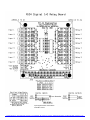
R104-88 User Guide
A) Relay Output Control
The 8 relays are accessed through I/O memory writes. The relays are grouped in sets of four, and the group I/O memory
address is an offset from the base decode address. Relays are grouped as follows:
Group 1: Outputs DO1 to DO4
Group 2: Outputs DO5 to DO8
I/O address = Base Address
I/O address = Base Address + 1
The relays are bit mapped to the lower four data lines in each group as follows:
Relay
SD3
SD2
SD1
SD0
Group 1
Relay4
Relay3
Relay2
Relay1
Group 2
Relay8
Relay7
Relay6
Relay5
B) Digital Input Reading
The 8 digital inputs are accessed through I/O memory reads. The inputs are grouped in sets of four, and the group I/O
memory address is an offset from the base decode address. Inputs are grouped as follows:
Group 1: Inputs DO1 to DO4
Group 2: Inputs DO5 to DO8
I/O address = Base Address + 2
I/O address = Base Address + 3
The inputs are bit mapped to the lower four data lines in each group as follows:
Digital Input
SD3
SD2
SD1
SD0
Group 1
Input4
Input3
Input2
Input1
Group 2
Input8
Input7
Input6
Input5
C) Base Address Setting
There are four decode base addresses, which are jumper selectable from the address select block J18.
Base Address
J18-1
J18-2
240H
Jumper Not Installed
Jumper Not Installed
260H
Jumper Installed
Jumper Not Installed
280H
Jumper Not Installed
Jumper Installed
300H
Jumper Installed
Jumper Installed
Tri-M Engineering • 1407 Kebet Way, Unit 100 • Port Coquitlam, BC V3C 6L3 • Canada • Office 604.945.9565 Fax 604.945.9566 • www.Tri-m.com
Input signal must be connected to
terminals 1 and 3
Tri-M Engineering • 1407 Kebet Way, Unit 100 • Port Coquitlam, BC V3C 6L3 • Canada • Office 604.945.9565 Fax 604.945.9566 • www.Tri-m.com