1
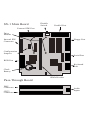
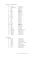
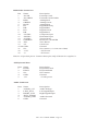
Paravision SX-1™
User’s Guide
Copyright 1994 Paravision, Inc. All Rights Reserved.
2nd Edition - July 1994
1. INTRODUCTION
Thank you for choosing the SX-1 expansion unit for your Amiga® CD32™ and
welcome to the world of personal computing. By adding the SX-1 to your
CD32 you transform an impressive game machine into a high-powered
multimedia computer system.
First, make sure that you received everything you need. In this package you
should have:
• the SX-1 unit
• a diskette of set-up software
• a warranty registration card
• this User’s Guide
If your SX-1 does not have a hard drive installed, you should also have a
small packet containing four screws and four plastic spacers.
If anything is missing, call our shipping department right away.
Take the time now to fill out the registration card. This information will allow
us to notify you of product updates. Your unit’s serial number is on the white
label attached to the back of the SX-1.
2. FEATURES AND SPECIFICATIONS
The SX-1 is a complex machine with many options. This section will take each
in turn and explain their uses and capabilities.
Inside the SX-1
Internal Drive Connector. This is a standard 44 pin connector for 2.5" IDE
Hard Disks. A hard disk lets you save programs and data just like a floppy
disk—except that it can access them much more quickly than floppies can, and
it can store a great deal more. A typical hard disk (60 megabytes) can store
almost 70 floppy disks worth of data.
Configuration Jumpers. These are used to configure some of your SX-1’s
SX-1 User’s Guide 2nd Ed. - Page 1
SX-1 Main Board
Disable
Switch
Parallel Port
External IDE Port
Drive
Mounts
Internal IDE
Connector
Floppy Port
Configuration
Jumpers
Serial Port
RGB Port
Keyboard
Port
Clock
Battery
SIMM Socket
Pass-Through Board
FMV
Connector
CD32
Connector
Audio
Inputs
options. They will be detailed later.
Battery for the Clock/Calendar Chip. This is a long-life CR2032 replaceable
lithium battery that can be found anywhere watch or camera batteries are
sold. Many programs need to know when files were last changed. With a
clock built into the SX-1, you won’t have to enter the date every time you
turn the power on.
72-pin SIMM Memory Connector. This is where you add memory to your
system. Computers use RAM as temporary, extremely fast storage for data
and programs. The more memory your system has, the more efficient it can
become. Increased memory can also let you run more programs at the same
time and work with larger data files.
Left Side Panel
RGB Video Connector. This is a standard DB23 Amiga Video connector.
Adding an RGB monitor will give you a much sharper picture than you can
get from the CD32’s composite video connector. If you have Commodore’s Full
Motion Video card, you can watch CD-I video disks with the clarity of an
RGB screen.
Back Panel
Parallel Connector. This is a standard DB25 Amiga 1200™ parallel port,
allowing you to connect most printers easily. Also, some video and audio
digitizers can plug in here.
Disable Switch. This switch allows you to disable most of the functionality of
the SX-1 board just in case you find any CD-based software that does not
work. Only the RGB port, memory and clock functions are left active when
this switch is set toward the parallel port. Normally you will leave it set
toward the External IDE connector. You will have to reset the machine each
time you change this switch.
DB25 Expansion Cutout. This opening allows you to add a SCSI interface card
and neatly mount the connector on the back panel.
External Hard Disk Connector. This DB37 connector lets you attach an
external IDE hard disk. This would be used when you have two hard disks
that you want to use, or when your hard disk is too large to fit inside the
SX-1.
Right Side Panel
Audio Input. This 6-pin Mini-DIN connector allows a third audio stream to be
mixed with the Amiga’s audio output and the CD player’s audio output. This
is not a digitizer—the Amiga can’t do anything with the signal that gets fed in
except send it out the normal CD32 audio connectors. With the proper cables,
you can attach a microphone and sing along with your music CD’s.
AT-101 Keyboard Connector. This connector allows you to plug in an
inexpensive “AT-101”-style keyboard as used on IBM® AT™ computers.
SX-1 User’s Guide 2nd Ed. - Page 3
9 pin IBM-compatible RS232 Serial Port. This port allows you to connect to
modems (by which your computer can share data with other computers
through the telephone lines), some printers, light pens, and other local
computers (through a special cable called a null-modem).
Amiga Floppy Drive Connector. This connector allows you to attach an Amiga
floppy disk drive to the CD32. Both normal Amiga drives (which store about
880 kilobytes of information) and the new Amiga high-density drives (which
store about 1.76 megabytes of information) are supported.
Pass-Through Board
Full Morion Video Connector. This is where you would attach Commodore’s
Full Motion Video (FMV) card.
CD32 Connector. This is where the SX-1 attaches to the CD32.
3. CONFIGURATION AND INSTALLATION
(1) Read through the entire installation procedure before even picking up a
screwdriver. If you have any questions, contact your dealer or Paravision’s
Technical Support department.
The standard power supply that comes with the CD32 is very weak. It has
enough power to run the CD32 itself and very little else. If you are using any
one of: one floppy drive, one hard disk, or Commodore’s Full Motion Video
module, you should have enough power to run reliably. If you are using
more than one, though, you probably will need a replacement power supply.
Consult your dealer for the availability of higher wattage power supplies.
Opening the SX-1
(2) If you do not need to open the SX-1’s case, skip to step 21: Connecting To
The CD32.
To open the SX-1’s case you will need a #1 Phillips screwdriver.
Locate or create a static-free workspace. Static electricity can seriously damage
any electronic device, and the CD32 and SX-1 are no exceptions. If you have
an electronics store nearby, the salespeople can supply you with and show
you how to use a grounding wrist strap.
(3) Locate the 4 screws (one on each corner) holding the SX-1’s top cover and
remove them. Lift the top cover straight up to remove it.
Hard Disk Installation
(4) If you are not installing an internal IDE hard disk, skip to step 16:
Installing Memory.
SX-1 User’s Guide 2nd Ed. - Page 4
To install an internal hard disk you will need a 5 millimeter nutdriver, a #1
Phillips screwdriver, a 44-conductor IDE cable approximately two inches long,
a 2 1/2" hard disk, and a copy of the AmigaDOS 3.x release disks, including
the Install disk.
The hard disk attaches upside-down, underneath the SX-1’s main board.
Because of this, you must remove the 10 hex-head screws from around the
SX-1’s external connectors in order to get the board out.
(5) Lifting the front (pass-through card) edge first, remove the SX-1’s main
board from the case. At this point, the silver shield around one or both of the
rear connectors may come loose. Don’t worry: just set it/them aside.
(6) Open the screw/spacer packet and insert one of the screws through one of
the hard drive mounting holes in the SX-1 board such that the head of the
screw is on the top side of the board.
(7) Place one of the plastic spacers over the end of the screw and line up one
of the mounting holes on the bottom of the drive with this screw. Make sure
that the drive’s connector is facing the IDE connector on the top of the SX-1
board. Start the screw, but don’t tighten it down yet. This step is rather
awkward—you might need someone to help hold things for you while you
get the screw going.
(8) Repeat steps 6 and 7 for each of the other three screws. Getting the spacers
in between the drive and board can be tricky after the first one, so be patient.
A small needle-nosed plier can sometimes help to get everything lined up.
(9) When all four screws are started into the drive, tighten them all down.
(10) Look between the drive and board very carefully. If any of the pins on
the back of the SX-1 touch any part of the hard disk, stop here. Don’t plug
the board into the CD32 just to see if it will work—serious damage to the disk,
SX-1, or CD32 is possible (maybe all three). Those pins will have to be
removed before it will be safe to use that hard disk on the SX-1.
(11) Connect one end of your drive cable to the SX-1’s IDE connector. If the
cable has a stripe down one edge, connect it so that this edge is toward the
back of the SX-1: over the pin marked “1” on the board.
(12) Connect the other end of the cable to the drive.
(13) Replace the connector shielding if any came loose in step 5. Notice how
the connectors are wider at the top than at the bottom. Make sure to put the
shield(s) back on with the wide portion at the top.
(14) Reinstall the SX-1 board into the case. If the drive hits the bottom of the
case and will not allow the connectors on the sides of the SX-1 to line up
with the holes in the case, call Paravision Technical Support for an alternate
spacer configuration.
(15) Reattach all the hex-head screws around the connectors. Don’t tighten any
of them down before getting all 10 started into their threads.
SX-1 User’s Guide 2nd Ed. - Page 5
Installing Memory
(16) If you are not installing memory, skip to step 19: Configuring Other
Options.
The SX-1 takes one SIMM (Single-row, In-line Memory Module) to provide
Fast Memory for the system. This can be 1, 2, 4, or 8 megabytes in size if you
do not have the Full Motion Video card; or 1,2, or 4 megabytes if you do
have the FMV.
This SIMM must be a 72-pin type, providing a 32-bit wide data path. There
are 36-bit wide SIMMs which will also work but the extra bits are not used in
the Amiga system. Memory chips also have a speed rating and this SIMM
must be rated at 80 ns (nanoseconds) or faster (a lower number is faster).
Look closely at your SIMM. You will notice that one of the lower corners has
a notch taken out of it. This notch keys the board so that it will go into the
socket in only one direction. This notch should be nearer the pass-through
board when you install the SIMM in the SX-1.
(17) Set the SIMM into the socket at an angle. Once the edge of the SIMM is
down in the teeth of the socket, rotate the SIMM so that it is standing
vertically in the socket. Two metal springs (one on each end) will snap into
place to hold the SIMM upright. To remove the memory, simply press the
metal springs away from the SIMM. It will pop out when it is loose.
(18) Set jumpers 1 and 2 according to the particular size of SIMM you have
installed. Set jumper 3, RAM Disable, ON for now. The RAM Test can be
more thorough when AmigaDOS™ isn’t already using the memory.
When a jumper is ON, it is connecting two pins. The best way to set a jumper
OFF is to leave it hanging off only one pin. This keeps them inside the
machine where they won’t get lost.
Configuring Other Options
(19) Jumper number 4 controls how long the system will wait on a cold boot
for the drive to get up to speed. If this jumper is on, the SX-1 will add an
additional 10 seconds to the boot up process. Most drives will not require this
extra delay, so for the first-time installation, leave it off. If, after it’s formatted,
the hard disk will not boot when you turn the CD32 on, but will boot just
fine when you press the reset button, try setting this jumper on.
The right-hand Alt (alternate) key is not present on some AT keyboards but is
required for many Amiga programs. If you want to use a keyboard that does
not have a right Alt key you can remove jumper 5. This will let you use the
right Control key, which the Amiga normally doesn’t have, as a right Alt key.
When your keyboard has a right Alt key, jumper 5 should be on. This makes
the right Control and Alt keys function normally.
(20) If you left the Memory Disable Jumper (#3) ON in step 18, continue with
the next section. Otherwise, re-attach the top cover to the SX-1, and screw it
SX-1 User’s Guide 2nd Ed. - Page 6
down.
Connecting to the CD32
(21) Detach all the cables from the CD32.
(22) Locate the removable panel on the back of the CD32 unit and remove the
screw holding it in place. Remove the panel.
(23) If you have a Full Motion Video board, remove it from its pass-through
board. Plug the FMV card into the top slot of the SX-1’s pass-through board.
(24) Line up the SX-1 with the CD32 so that the bottom slot of the passthrough board connects with the CD-32’s expansion bus. Then press the two
together. Be very careful that the connectors are well-seated before turning on
any power.
(25) Reattach the cables to the CD32 and attach any new devices to the SX-1’s
connectors.
Memory Testing
(26) If you want to run the RAM test, or if you have just changed the
memory and need to run the RAM test, continue reading here. Otherwise,
skip to step 29: Hard Disk Setup.
Boot up the system from a Workbench™ disk, either on hard disk or a floppy.
If the system won’t boot: turn it off, recheck the connections and try again.
(27) When the Workbench screen appears insert the SX-1 Utilities disk, doubleclick the SX-1 diskette icon, and then the MBRTest-2 drawer. Double-click the
MBRTest-2 program icon. Select the area of memory labelled “MBX1200Z”,
select as many test options as you want, and click on the “START” button.
(28) If the RAM test runs without problem: turn off the power, set the
Memory Disable Jumper (#3) OFF, and close up the SX-1’s top cover.
If there was an error, double check the jumper settings and all the connections
and try the test again. If there is still a problem, contact your dealer or
Paravision about getting the SIMM and/or SX-1 tested.
Hard Disk Setup
(29) If you have not just installed a hard disk, then you’re done.
Every hard disk needs some setup before it can be used. You have to define
at least one partition, which is a named area of a hard disk. You can divide
a disk into any number of partitions and each one will show up on the
Workbench screen as if it were a separate drive. Normally, though, you
won’t divide a disk at all, or if you do, not into partitions any smaller than 40
or 50 megabytes.
(30) Boot the system with your copy of the AmigaDOS 3.x Installation disk.
SX-1 User’s Guide 2nd Ed. - Page 7
Double-dick the disk icon, then open the HDSetup drawer. Select the
language you wish to use and follow the prompts to partition the hard disk.
At one point it will ask for a unit number: enter 0.
(31) When the partitioning is done, close the HDSetup drawer, open the Install
drawer, and double-dick the icon for your language. Follow the prompts to
install AmigaDOS onto your hard disk.
Congratulations, you’re done!
4. USING AN AT-101 STYLE KEYBOARD
The keyboard connector on the right side of the SX-1 allows you to use
inexpensive “AT-101 Key” keyboards to run your CD32.
Selecting A Keyboard
Before purchasing a keyboard to use with your SX-1, make sure that it is in
fact an AT-101 style keyboard, not a PC keyboard. Ordinary PC keyboards
will not work. The AT-101 style can be identified by the extra function keys
”F11" and “F12”, and by the cursor keypad separate from the numeric keypad.
Also, we recommend that the keyboard you select has two separate “Alt” keys:
one on the left side and one on the right.
Many keyboards are switchable between AT and PC compatibility. Check the
documentation that comes with your keyboard and configure it for AT
compatibility. On some keyboards this is controlled by a switch on the bottom
that is easily changed by setting the keyboard down on anything other than a
clean desk. If at some time you find your keyboard no longer works, double
check this switch.
Some keyboards automatically detect whether they are attached to an AT or a
PC. These “auto-sensing” keyboards will probably not work.
Using Your Keyboard
Because there are differences between the AT keyboard layout and the normal
Amiga keyboard layout, some keys will not function according to the legends
printed on the keytops.
AT Key Label Amiga Function
F11
Left (solid) Amiga key (appears as a Commodore™
logo on some Amiga keyboards)
F12
Right (open) Amiga key
Print Screen
Sys Req
Home
End
Help key
Help key
Shift-Cursor Left
Shift-Cursor Right
SX-1 User’s Guide 2nd Ed. - Page 8
Page Up
Page Down
Shift-Cursor Up
Shift-Cursor Down
Insert
Pause
Break
not defined
not defined
not defined
Num Lock
this key behaves just as it does on AT computers (see
below)
used to control “Sticky” mode (see below)
Scroll Lock
There are two keys on the standard American Amiga keyboard that are not
present on an AT keyboard. The Open and Close Parentheses on the Amiga’s
numeric keypad cannot be generated.
Using The Num Lock Key
The NumLock (Numeric Pad Lock) key is used to switch the numeric keypad
between producing numbers and producing cursor movement keys. When the
NumLock light is on, the keys will generate numbers. When the NumLock
light is off, the keys will act to move the cursor.
Just like an AT, holding down either Shift key will temporarily reverse the
NumLock state (it won t change the light, though.) Some Amiga programs use
the shift keys to modify the meaning of the cursor keys; and you will have to
be careful if you try to use the numeric pad with these programs. We
recommend leaving Numlock on and using the numeric keypad only for
numbers and using only the cursor keypad for cursor movement.
Using The Scroll Lock Key
Since the Amiga has no provision for a Scroll Lock feature like the one the
AT has, the Scroll Lock key has been used to implement something new to
the Amiga. Persons for whom it is difficult or impossible to hold down
multiple keys at once can activate “Sticky Mode” by pressing the Scroll Lock
key for two seconds. When Sticky Mode is active, the Scroll Lock light will go
on whenever the Scroll Lock key is pressed.
In Sticky Mode, any modifier keys that you press (Shift, Control, Alt, or
Amiga Keys) will “stick”. That is, the Amiga will not be told when the key is
released. Instead, the modifier will be kept active until a nonmodifier key is
pressed (anything other than the Shift, Control, Alt, or Amiga keys). The
Scroll Lock light will be turned on to show you that a key is being held for
you. When you press a non-modifier key, all the held modifiers will be
released and the Scroll Lock light will be turned off.
For example: if you need to type a Right-Amiga-Q you would first press the
Right Amiga (F12) key. The Scroll Lock light would go on to tell you that the
Right-Amiga modifier is being held for you. Then you would press the “Q”
key. At this time the Amiga gets the Right-Amiga-Q. When you release the
”Q” key, the stored Right-Amiga modifier is released, and the Scroll Lock light
is turned off.
SX-1 User’s Guide 2nd Ed. - Page 9
If a modifier key is pressed, but you then decide to do something else,
tapping the Scroll Lock key will release all held modifiers.
To deactivate Sticky Mode, hold down the Scroll Lock key for two seconds.
When the Scroll Lock light goes off, Sticky Mode has been released,
Be particularly careful when using the Control and Amiga keys. Either
Control key plus both Amiga keys (F11 and F12) will reset the CD32 just as
Control-Amiga-Amiga would on a normal keyboard.
Other Differences
Some key combinations are used by Amiga software, but are not supported by
IBM software. These key combinations may or may not be implemented by
your keyboard. In particular, moving the mouse pointer by the equivalent key
presses (either Amiga key plus a cursor key) has been found to be impossible
with many keyboards. This problem is inside the AT keyboard and cannot be
fixed in our translation software.
Most AT keyboards use Shift-Tab to move the cursor back to the nearest tab
position to the left. You will see a left-pointing arrow at the top of your Tab
key. This function is not built into the Amiga’s operating system software, so
some of your programs may not support it.
SX-1 User’s Guide 2nd Ed. - Page 10
5. TECHNICAL SUPPORT
If you have any suggestions for improving this documentation or the product
in general, please drop us a note.
Should you have any problems, please contact your dealer first. If you need
further assistance, contact our Technical Support department.
Paravision, Inc.
500 East Arapaho, Suite 104
Richardson, Texas 75081
United States of America
Phone : +1 (214) 644-0043
Fax : +1 (214) 644-7916
Internet
: [email protected]
Our telephone lines are open Monday through Friday, 09:00 to 17:00 US
Central Time.
6. CREDITS, COPYRIGHTS AND TRADEMARKS
Product Design: Jerry Robinson, Redmond Simonsen, Yan Sun
Software Design: Dan Barrans, Joanne Dow, Mike Pinson
Documentation: Bill Knox, Mike Pinson
Package Design: Robert Maynard
This document, its packaging, and accompanying software are Copyright
©1994 Paravision, Inc., all rights reserved.
‘SX-1" is a trademark of Paravision, Inc. “Amiga” is a registered trademark and
”Amiga CD32", “Amiga 1200”, “AmigaDOS”, and “Workbench” are trademarks
of Commodore-Amiga, Inc. “Commodore” is a registered trademark of
Commodore Electronics, Limited. “IBM” is a registered trademark and “AT” is
a trademark of International Business Machines Corporation.
SX-1 User’s Guide 2nd Ed. - Page 11
APPENDIX A: CONNECTOR PINOUTS
Parallel Connector
Pin Name
1
/STROBE
2
D0
3
D1
4
D2
5
D3
6
D4
7
D5
8
D6
9
D7
10 /ACK
11 BUSY
12 POUT
13 SEL
14 +5V
15 NC
16 /RESET
17-25 GND
Description
Strobe
Data bit 0 (LSB)
Data bit 1
Data bit 2
Data bit 3
Data bit 4
Data bit 5
Data bit 6
Data bit 7
Acknowledge
Busy
Paper Out
Select
5V Power
No Connect
Printer Reset
Signal Ground
Pins 17-25 are signal grounds. Do not connect them directly to a shield
ground. Pin 14 provides +5V power. Connect this pin only if power is
required by the external device.
Floppy Disk Connnector
1
2
3-7
8
9
10
11
12
13
14
15
16
17
18
19
20
21
22
23
/RDY
/DKRD
GND
/MTRXD
/SEL1
/DRES
/CHNG
+5V
/SIDE
/WPRO
/TK0
/DKWE
/DKWD
/STEP
DIRB
/SEL2
/SEL0
/INDEX
+12V
Disk Ready
Disk Read Data
Ground
Disk Motor Control
Select Drive 1
Disk Reset
Disk Changed
+5V Power
Disk Side Select
Write Protected
Track 0 Detected
Disk Write Enable
Disk Write Data
Step Disk Heads
Select Head Direction
Select Drive 2
Select Drive 0
Disk Index Pulse
+12V Power
SX-1 User’s Guide 2nd Ed. - Page 12
External
IDE Connector
Pin Name
1
/IDE-RESET
2
D0
3
D2
4
D4
5
D6
6
GND
7
D8
8
D10
9
D12
10
D14
11-17 GND
18-19 +5V
20
GND
21
D1
22
D3
23
D5
24
D7
25
GND
26
D9
27
D11
28
D13
29
D15
30
/IOW
31
/IOR
32
IDE-IRQ
33
IDE-A2
34
IDE-A1
35
IDE-A0
36
/BICS1
37
/BICS0
Description
Drive Reset
Data bit 0
Data bit 2
Data bit 4
Data bit 6
Ground
Data bit 8
Data bit 10
Data bit 12
Data bit 14
Ground
5V Power
Ground
Data bit 1
Data bit 3
Data bit 5
Data bit 7
Ground
Data bit 9
Data bit 11
Data bit 13
Data bit 15
I/O Write
I/O Read
Interrupt Request
Address bit 2
Address bit 1
Address bit 0
Chip Select 1
Chip Select 0
Serial Port
Pins
1
2
3
4
5
6
7
8
9
Name
DCD
RXD
TXD
DTR
GND
DSR
RTS
CTS
RI
Description
Carrier Detect
Receive Data
Transmit Data
Data Terminal Ready
Ground
Data Set Ready
Request To Send
Clear To Send
Ring Indicate
SX-1 User’s Guide 2nd Ed. - Page 13
RGB Video Connector
Pin Name
1
/XCLK
2
/XCLKEN
3
RED
4
GREEN
5
BLUE
6
DI
7
DB
8
DG
9
DR
10
/CSYNC
11
/HSYNC
12
/VSYNC
13
GNDRTN
14
/ZD
15
/CI
16-20 GND
21
NC
22
+12V
23
+5
Description
Externa] Clock
External Clock Enable
Analog Red
Analog Green
Analog Blue
Digital Intensity
Digital Blue
Digital Green
Digital Red
Composite Sync
Horizontal Sync
Vertical Sync
Return for /XCLKEN
Zero Detect
Clock Out
Ground
No Connect (-12 volts on A1200)
+12V Power
+5V Power
Pins 21-23 provide power. Connect these pins only if the device requires it.
AT Keyboard Port
Pins
1
2
3
4
5
Name
KCLK
KDAT
NC
GND
+5V
Description
Keyboard Clock
Keyboard Data
No Connect
Ground
+5 volts power
Audio Connector
Pins
1
2
3
4
5
6
Name
AUDIO_12V
LEFT_EXT
RIGHT_EXT
/EXT_AUDIO
AUDIO_GND
GND
Description
Audio Voltage
Left Signal Input
Right Signal Input
Audio Ground
Ground
SX-1 User’s Guide 2nd Ed. - Page 14
APPENDIX B: QUICK REFERENCE JUMPER SETTINGS
“ON” indicates that a jumper block is connecting two pins. “OFF” means that
the jumper block is either detached completely, or is hanging off only one pin
of the pair.
Jumper Function
1
Controls the number of memory banks contained on the SIMM
ON = 2 Banks of Memory (a 2 or 8 Megabyte SIMM)
OFF = 1 Bank of Memory (a 1 or 4 Megabyte SIMM)
Default position: OFF
2
Controls the size of the memory banks contained on the SIMM
ON = 4 or 8 Megabyte SIMM
OFF = 1 or 2 Megabyte SIMM
Default position: OFF
3
Disables Memory Configuration
ON = Defeat Autoconfiguration or No Ram Installed
OFF = Normal Autoconfiguration
Default position: ON
4
Power On Delay
ON = Adds additional 10 seconds for hard drive to spin up on
initial cold starts
OFF = Normal boot time
Default position: OFF
5
Right Alt control for AT keyboards
ON = Keyboard has two ALT keys
OFF = Keyboard has no right ALT key so function is mapped to
right CTRL key
Default position: ON
SX-1 User’s Guide 2nd Ed. - Page 15
Amiga Hardware World
Everything about Amiga hardware...
~
http://amiga.resource.cx