1
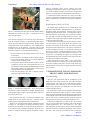
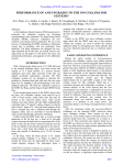
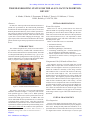
Proceedings of PAC09, Vancouver, BC, Canada
MO6PFP087
TROUBLESHOOTING STATUS FOR THE ALS IN-VACUUM INSERTION
DEVICE∗
A. Madur, S. Marks, S. Prestemon, D. Robin, T. Scarvie, R. Schlueter, C. Steier,
LBNL, Berkeley, CA 94720, USA
Abstract
INITIAL OBSERVATIONS
In 2006, the 30mm period In-Vacuum Insertion Device
(IVID) was operational for the femtosecond phenomena
beamline at the Advanced Light Source (ALS) of Lawrence
Berkeley National Laboratory. Since routine operation began a series of partial or total beam losses as well as coincident sudden pressure increases within the IVID vacuum
system have occurred while changing the IVID gap. This
paper reports these observations and describes the investigations and the repair attempt performed on this insertion
device.
INTRODUCTION
The Advanced Light Source (ALS) at Lawrence Berkeley National Laboratory installed and commissioned its
first In-Vacuum Insertion Device (IVID) in 2006. The IVID
was designed and built by the Neomax Corp. [1] as a collaboration with the Spring8 insertion device group [2]. This
IVID is dedicated to two femtosecond phenomena beamlines [3]. Figure 1 shows a picture of the IVID.
Events Description
Beam losses as well as pressure bursts were observed
while the IVID was operating at small gaps. This occurred
particularly for currents above 200 mA and up to the maximum ALS current of 500 mA. Because of the rapid nature
of the observed beam losses, it was impossible to distinguish between the cause and effect relationship of beam
loss and pressure spike.
Below are listed the causes we considered:
•
•
•
•
mechanical obstacles,
damaged conductive foils,
misbehaving RF fingers, bad contacts,
overheating conducting foil: vibrations during motion, misalignment, bad thermal conduction,
• release of particles due to friction between two moving surfaces in contact: bellows, cooling parts of the
transition pieces
Components Likely Related to Beam Loss
Figure 1: ALS In-Vacuum Insertion Device
The IVID is 2.05 m long, 30 mm period hybrid planar
undulator (Permanent magnet + iron poles) with a minimum operation gap of 5.5 mm (1.52 T). While operating
at smaller gaps, beam losses (total or partial) have been associated with IVID gap movement. To address this issue
and to understand this unexpected behavior, we started investigating all the possible causes. This paper reports the
observations we performed, a review of the conductive foil
replacement, and the experiments performed during accelerator physics shifts after the conductive foil replacement.
∗ This work was supported by the Director, Office of Science, U. S.
Department of Energy under Contract No. DE-AC02-05CH11231.
The magnetic structure is located within the vacuum
chamber and a 110µm thick Cu-Ni conductive foil is installed over both magnetic structures (top and bottom) to
ensure the conductive continuity of the image currents.
This conductive foil is 110 mm wide and covers the magnets over the whole length (1.5 m). The Cu-Ni foil was
obtained from a 60 µm thick sheet of copper, plated with
nickel (50µm). The magnetic properties of the nickel are
used to ensure adhesion of the foil to the magnets; this provides the heat conduction path for foil cooling. At both
ends, the foils are clamped to the water-cooled transition taper plates made of OFHC copper (Oxygen-Free High Conductivity). These taper plates along with the sliding contacts ensure the transition between the fixed gap vacuum
chamber and the undulator varying gap for the continuity
of the image currents. Figure 2 shows the transition we just
described.
INITIAL DIAGNOSTICS
First Inspection
In spite of the initial observations (beam losses + pressure bursts) we lacked instrumentation to properly diagnose
these issues. During the May 2008 ALS shutdown, we inspected the interior of the IVID with a borescope connected
to a digital video camera. The borescope we used is rigid
Magnets
T15 - Undulators and Wigglers
333
MO6PFP087
Proceedings of PAC09, Vancouver, BC, Canada
chlorine, chromium, cobalt, copper, iridium, iron, lead,
magnesium, molybdenum, nickel, oxygen, potassium, silicon, sulfur, titanium and zinc. The presence of copper and
nickel is consistent with our interpretation from the Fig. 3
i.e. deterioration of the conductive foil. After several discussions with Spring8 [2] and colleagues from the insertion
devices community, we decided to replace the conductive
foils.
Cu Taper plates
Sliding contacts
e− beam
Replacement of the Cu-Ni Foils
IVID Entrance
Figure 2: Transition parts between vacuum chamber flange
and IVID gap (from left to right) - Cooling lines are not
shown on this picture
and is 80 mm long. Since we could only access the interior
from the viewport windows, we inspected the ends region.
These regions include the transition plates, the RF fingers
and the extremities of the undulator i.e. the conducting foil
installed on top of the magnets. From the ends we had
a global view of the inside of the IVID vacuum chamber.
From the inspection we determined the following:
• no discoloration on the sliding contacts: they are not
overheating,
• no discoloration on each part of the transition regions,
• some small scratches (order of 1 mm wide) and some
wrinkles on the conductive foil,
• an important discoloration around one hole on the
conductive foil; the foil is designed with pairs of 2
mm diameter holes distributed longitudinally near the
outer edges in order to get a flat surface on the foil (no
trapped volume) after its installation,
• some dust deposition; this dust is aligned with the
transverse edges of the magnets.
We replaced the conductive foil in collaboration with
the device manufacturer, Hitachi-Neomax [1] during the
September 2008 ALS shutdown. With the help of three
qualified technicians from Japan, we managed to remove
the IVID from the ALS storage ring, replace the conductive foils and re-install the IVID within four weeks. The
conductive foils replacement also provided an opportunity
to directly inspect the IVID.
The main observation from this work is that the conductive foil seemed to be in good shape; the scratches were
relatively small and to be acceptable; they likely occurred
during the initial IVID assembly. The picture of the discoloration around the hole (Fig. 3) was actually showing an
extra layer of nickel. During the plating process, it sometimes happens that some nickel material overflows to the
copper side. Consequently no copper was missing at that
location and the presence of nickel on the copper side does
not affect the conductive foil quality.
While inspecting the “old” foils, we also noticed tiny
brown spots that were randomly spaced all along the foil.
It was not possible to tell if they were the result of the original fabrication or if they have been generated by vaporized
pieces of dust.
COMMISSIONING AND ACCELERATOR
PHYSICS SHIFT OBSERVATIONS
Commissioning
Figure 3: Pictures from inspection. Left: discoloration
and missing copper around a hole. Middle: dust deposited
along magnet edges. Right: Line of dust and a scratch on
the surface (shiny spot)
The left picture from Fig. 3 captured our attention. Our
interpretation of this picture was that it showed copper
peeling off and cracking due to heat induced stress.
Moreover we collected some samples of the dust in order
to analyze it. The analysis has been performed by Evans
Analytical Group (EAG) [4] using the Energy Dispersive
X-ray Spectroscopy method to determine the dust composition. The dust materials include: aluminum, carbon,
After the foil replacement and the installation of the
IVID back in the ALS storage ring, the IVID was again
commissioned. The result of the commissioning demonstrated that the beam dynamics in term of tune, lifetime,
dipole errors and beam size instability were not affected
with the attempted repair.
We checked the IVID vertical alignment with the electron beam and found an offset of 200 µm which is similar
to the one measured before the conductive foil replacement.
An alignment of the IVID will be scheduled in the near future in order to have a balanced beam clearance and heat
deposition between the top and bottom conductive foils.
Following re-installation of IVID in the ALS storage
ring, it took more than three months to achieve the desired
vacuum performance, 10 −11 Torr range (10 −9 Pa). Thermal outgassing was the result of image current heating and
upstream synchrotron radiation dissipating in the conductive foils. This issue has prevented us from operating at
Magnets
334
T15 - Undulators and Wigglers
Proceedings of PAC09, Vancouver, BC, Canada
MO6PFP087
small gaps and we had to limit the operational gap to 10
mm for initial operation. Beam losses and pressure bursts
were again observed at smaller gaps .
Although the conductive foil replacement improved our
knowledge concerning the state of the IVID, it did not resolve the issue of the spurious beam losses and pressure
bursts. We are dedicating some time during the accelerator
physics shifts to continue investigating the probable causes
of our problems.
We are continuing our efforts to track the instability
source(s). One of them could be the dust deposited on the
IVID conductive foils. We are investigating the possibility
to isolate the IVID vacuum during maintenance operations
by adding a vacuum valve. If the dust particle source is located beyond the IVID, such a valve may reduce deposition
of these particles within the IVID.
Accelerator Physics Shifts
The list of possible causes for beam instability associated with IVID operation is getting shorter but this is still
a work in progress. Future investigations include a plan to
tune the feedback system to make the beam less stable and
consequently more sensitive to any instability. The purpose
is to be able to reproduce the beam losses we experience
so that we can increase event statistics and hopefully identify their cause(s). We also plan to use a fast oscilloscope
triggered right after a beam loss to determine the speed of
propagation of the instability.
Troubleshooting the IVID to allow it to operate at small
gaps has become an unexpectedly long project. While
we are continuing our investigations, we are still learning
about its behavior. The random nature of the instabilities
makes it difficult to methodically study the problem. Improved diagnostics will aid in determining and eliminating
the source of losses.
As the statistics for beam losses events was small and the
reproducibility of such events was not evident, the goal of
the dedicated accelerator physics shifts is to find the conditions that consistently trigger these events.
Gap motion We focused our initial attention to the gap
motion. Most of the events were indeed observed while the
IVID gap was changing and only in the closing direction.
Since we were not able to close the IVID to small gaps directly (≤ 9mm) consistently without beam loss, we tried
to find a process that would allow us to reach any desired
gap without beam losses. We closed the IVID gap by small
steps (100µm) from 9.5mm to 5.5mm gaps at a speed of
1 mm/s, waiting for the vacuum to recover between each
step. We repeated this experiment twice and both experiments were conducted at high beam current (500 mA and
440 mA).
Beam losses from the mA range to the 100 mA range
were observed and they occurred at similar gaps for both
experiments except for the 5.5 mm gap. At this gap, the
speed was different for each experiment and and a beam
loss was observed at the highest speed (1 mm/s vs 0.1
mm/s). When the beam losses occurred, some vacuum activity was observed (ΔP max = 11.10−10 Torr) but it seems
to be too small to likely cause the beam losses.
One important observation we made during this shift is
that when the beam losses occurred, we could see through
the synchrotron radiation monitor that the beam was blowing up in the vertical direction before recovering its normal
shape in the cases of partial beam losses.
CONCLUSION
ACKOWLEDGMENT
We would like to thank Spring8 and Hitachi-Neomax
colleagues for the fruitful collaboration.
REFERENCES
[1] Hitachi-Metals company,
metals.co.jp/e/index.html
Neomax,
http://www.hitachi-
[2] Spring 8, http://www.spring8.or.jp/en/
[3] C. Steier, P. Heimann, S. Marks, R. Schoenlein, W. Wan, W.
Wittmer, Successful completion of the femtosecond slicing
upgrade at the ALS, PAC 07
[4] Evans Analytical Group (EAG), http://www.eaglabs.com/
Closing to minimum gap When the IVID vacuum became good enough (10 −11 Torr range (10 −9 Pa)) we could
manage to close it to the minimum gap gradually. This important step allowed us to dedicate some time to scrubbing
and thus improving the IVID vacuum. However, one of the
first times we left the IVID at the minimum gap, we saw
sudden pressure spikes happening without beam loss.
Then we were able to close the IVID to the minimum gap
directly without experiencing any beam losses except for
one particular case. The first successful attempts to close
the gap were performed while the orbit feedback was on
and all the insertion devices where wide open. When we
performed the same experiment with all the insertion devices closed, we experienced a partial beam loss between
the 6 mm and 5.5 mm gaps.
Magnets
T15 - Undulators and Wigglers
335