1
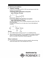
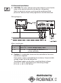
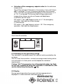
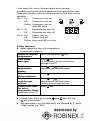
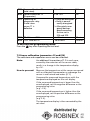
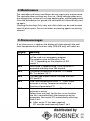
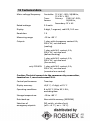
PCR-310
PCR-410
with TR-310
Installation and
Operating Instructions
EB-PCR-05
EN1H-1923GE23 R0106
Electronic refrigeration control
with mains transformer
TABLE OF CONTENTS
11 Unpacking the unit and conditions of use
3
12 General instructions
3
13 Use and function
3
3
4
3.1 Use for the purpose intended
3.2 Function
14 Safety
5
5
5
4.1 Sources of danger
4.2 Safety precautions
15 Installation and commissioning
5.1 Mechanical installation
5.2 Electrical installation
5.3 Setting the dip switch for the emergency setpoint
16 Operation of the controller
6.1
6.2
6.3
6.4
6.5
Switching on the operating voltage
Display
Key functions
Adjusting the cold store temperature
Changing the cold store temperature difference, defrost cycle,
and alarm temperature
6.6 Manual defrosting
17 Programming
7.1 Input parameters and ranges
7.2 Sensor calibration (parameters E 15 and E 16)
6
6
7
8
9
9
9
10
11
11
12
12
12
14
18 Maintenance
15
19 Alarm messages
15
10 Problem solving
16
11 Conditions of warranty
16
12 Technical data
17
2
1 Unpacking the unit and conditions of use
Before and when unpacking the unit, make a visual inspection to
identify any possible damage which may have occurred during
transportation. Please look for loose parts, dents, scratches, etc.
Report any damage immediately to the freight company. (Please see
“Conditions if damage has occurred”.) In other cases, the latest edition
of the “General conditions for the supply of goods and services” issued
by the ZVEI (German Central Association for the Electrotechnical
Industry) shall apply.
Before disposing of the packaging, please check it for loose functional
parts and information leaflets.
So that we can process warranty claims, please give an exact
description of the defect (with a photograph, if appropriate) and state
the model designation of the unit.
Please keep these operating instructions at the place where the
equipment is used.
2 General instructions
Work on the electrical devices and switching equipment may only be
carried out by appropriately qualified personnel. The relevant safety
and environmental regulations must be followed.
FLICA equipment is free from PCBs, PCTs, asbestos, formaldehyde,
cadmium and water-repelling substances.
The design of the equipment has taken into account the Standards
EN 50081-1,2 (emitted interference), EN 50082-1 (immunity to
interference), EN 60335-1 (electrical safety),
IEC 695-2-1 to -2-3 (fire resistance, glow-wire test).
Safety tests in accordance with EN 60335-1 (DIN VDE 0700 T500) have
been performed in the factory on all equipment.
3 Use and function
3.1 Use for the purpose intended
I This controller is designed to control ambient and media
temperatures in cold stores and refrigeration systems and to
control existing defrost equipment for one refrigeration circuit in
each case.
3
I
The controller must not be used as a safety cut-out device or excess
temperature limiter.
I The controller should preferably be connected to the mains
transformer supplied with the unit. Where the power supply is
provided by the customer, the permissible voltage ranges must be
adhered to.
I The mains transformer supplied with the equipment is only to be
used with the PCR-310 and PCR-410 controller.
If the controller and/or transformer are used for purposes
other than those stated here, it shall not be considered to be
use for the purpose intended.
I Only connect sensors supplied with the unit. If a replacement
sensor is required, only use sensors of the same type (part no.
H61007).
I The controller is not intended for use in vehicles because the
possible operating voltage ranges, interference level and
environmental operating conditions exceed the limits for which
the controller can be used.
I Please take the application limits into account
(see Technical Data, Chapter 12).
3.2 Function
The PCR-310/-410 are microprocessor-controlled cold store controls for
refrigeration and deepfreeze systems with a “snap-in” installation
housing to fit in an aperture 28.5 x 70.5 mm and featuring:
I Compressor control (dependent upon cold store
temperature) with delayed start-up.
I Evaporator fan control
u Fan either in combination with compressor or
u operating continuously or
u switched via the evaporator thermostat.
I Defrost control limited thermostatically, either for
electrical heating or hot-gas defrosting.
Defrosting is initiated via programmable intervals of time,
max. 24/day.
I Only PCR-410 with alarm output with relay, closer contact.
A mains transformer supplied with the unit is provided as a power
supply.
4
4 Safety
4.1 Sources of danger
I Caution - Mains voltage!
I Never expose the unit or transformer to water or moisture. Risk of
malfunction and short circuit. Only use the unit when it is adjusted
to normal ambient temperature (+15 to +30 °C). Extreme changes
in temperature in combination with high atmospheric humidity
may lead to the formation of condensed water.
I Even if the control-circuit voltage is switched off, high voltage may
still be applied to the unit. For this reason, isolate all electric
circuits before starting any service work.
I Never expose the unit or transformer to excessive heat, dust and
vibrations. Avoid knocks and pressure loads. If the housing is
damaged, there is a risk of an electric shock causing death or injury.
I If the unit cannot be operated without the risk of danger, it must
be taken out of service and precautions taken so that it cannot be
switched on again unintentionally.
This applies, in particular, if:
u The housing has damage which is visible,
u the unit is no longer operational or
u it has been stored for a long time in unfavourable conditions.
I The unit and transformer must not be opened. If the unit or
transformer is assumed defective, send it back to the dealer or
manufacturer with a precise description of the defect.
4.2 Safety precautions
I All electromagnetic loads (solenoid valves, contactors, alarm horns,
motors) should be interference suppressed directly at the coil with
RC elements. Please note the maximum contact rating of the relays
and terminals.
If this is not observed, there is a risk that the contacts may pit or
stick, with the result that the refrigeration system will not operate
correctly and the refrigerated items may be damaged.
I Sensor leads are to be routed separately from mains voltage wires:
the clearance should be at least 5 cm.
I Sensor leads must not be routed in multiple cables with other leads
carrying mains voltage, otherwise the system may malfunction.
I Tighten the terminals carefully; excessive strain will result in
damage to the controller or transformer.
5
5 Installation and commissioning
5.1 Mechanical installation
I “Snap-in” housing:
Fit the unit in an aperture 28.5 x 70.5 mm and secure it with the
relevant mounting frame
a) housings with terminal box cover plate
(max. thickness 22 mm):
b) housings without terminal box cover plate
(max. wall thickness 18 mm):
For walls thicker than 10 mm: remove side plastic spacers from the
mounting frame.
For the final fixing at the unit side screws have to be tightened
carefully.
Sensor:
I Use a cable clamp to secure sensor T1 in a suitable position.
I Secure evaporator sensor T2 in the evaporator fin core at the point
where it is suspected icing is the greatest. It is advisable to use a
point in the lower third of the finned evaporator.
Mains transformer:
I Fit onto back panel of electrics cabinet using the side mounting
holes and screws with a max. diameter of 3.5 mm.
6
5.2 Electrical installation
☛ CAUTION: The mains voltage and system frequency must be the
same as the nominal values on the device’s rating plate.
Work on electrical systems must be performed by qualified
personnel. Relevant local safety regulations must be observed.
Wiring diagram;
Mains transformer:
Terminal:
1–2
3–4
Description:
230 V AC = Mains voltage supply, input
12 V AC = Low voltage, on terminal 8 – 9
of the controller.
☛ Caution: It is preferable to connect the controller to the mains
transformer supplied.
If the power supply is provided by the customer, the permissible
voltage ranges are to be adhered to.
The voltage supply may be either smoothed direct voltage
(12 V DC +/- 10 %) (any polarity) or alternating voltage
(12 V AC +/- 10 % / 50 - 60 Hz).
7
Controller
Connection:
Description:
1–2
V
= Compressor contactor (cooling)
1 – 4 (PCR-410) Alarm
= Remote alarm, indicator lamp
or contactor
1–5
Ev
= Evaporator fan (contactor)
8–9
12V AC/DC = Power supply
10 – 11
T1
= Cold store sensor
10 – 12
T2
= Evaporator sensor
☛ Instructions:
I The total current via terminal 1 of the common relay connection
must not exceed 10 A.
I Pay attention to the contact loading of the relay
(8 A resistive load, 2A inductive load). As a general rule, contactors
are recommended.
I The maximum tested sensor cable length is 50 m, with a minimum
cross section of 2 x 0.75 mm2. Solder the extension cable to the
sensor cable to prevent contact resistances.
I It is advisable to use shielded sensor extension cables.
All shields must be routed at the side of the controller to one
earth/protective potential. The extension cable shield must not be
connected on the sensor side, otherwise bonding currents may
occur via the shielding.
I The controllers are designed respecting the highest degree of
immunity to interference. If the local interference level exceeds the
immunity data might get lost (AL1 in display) and the controllers
switches to the preprogrammed setting values. This is not a
mulfunction of the controller. In such cases the means to suppress
interference have to be improved (RC-elements, shielded lines).
5.3 Setting the DIP switch for the emergency setpoint
The DIP switch is at the side of the controller.
8
I
Selection of the emergency setpoint value for the cold store
temperature:
This will be activated if the data in the memory is lost and if alarm
AL1 is activated. This sets all program parameters to the preset
value. The cold store temperature setpoint can be preset to +4 °C
or –18 °C, as desired. This ensures that chilling systems with
temperatures above zero do not freeze and deepfreeze
installations do not thaw.
DIP switch 1, Pos.: off: Setpoint value at +4 °C for emergency
operation. Advisable for chilled storage
(= Preset value).
DIP switch 1, Pos.: on: Setpoint value at –18 °C for emergency
operation. Advisable for deepfreezers.
6 Operation of the controller
Front view of controller:
6.1 Switching on the operating voltage
The controller is started by means of a control switch provided by the
customer.
The first time the controller is started, pre-programmed setting values
are used which at a later point can be adapted for individual
requirements.
If alarm “AL 2” (temperature in refrigerated chamber too high
or too low) is displayed when the controller is switched on, this
can be cleared by pressing the
key.
6.2 Display
During normal operation the current cold store temperature is
displayed. It is measured with cold store sensor T1.
9
In the event of an alarm, the most recent alarm message
(e.g. AL1) and the cold store temperature are displayed alternately.
Three spot indicators show the switching status of the relays during
operation:
Pos. 1: On :
Compressor relay on.
Off:
Compressor relay off.
Flashes: Compressor start-up
delay E05 active.
Pos. 2: On :
Evaporator fan relay on.
Off:
Evaporator fan relay off.
Pos. 3: On:
Defrost relay on.
Off:
Defrost realy off.
Flashes: Drain time E09 is running.
6.3 Key functions
☛ Never operate the keys with sharp objects
(screwdriver or similar).
Display of setpoint
temperature:
Clear alarm
messages:
Evaporator
temperature
display:
Manual
defrost initiation:
Display of time
until the next
defrost:
Display limit value
for excess
temperature alarm:
(cold store sensor T1)
I
I
Press and hold down
key.
Press
key.
(If the sonsor is faulty, switch mains
voltage ON/OFF).
Press
and
keys in
sequence and hold both down.
Press
key for 5 seconds.
Press
and
keys in
sequence and hold both down.
(Display in hours and minutes).
Press
key.
Change input values by using the
and
keys with the
key pressed down.
Input parameters, e.g. the differential, are indicated by “E” and a
2-digit number, e.g. “E01”.
10
I
I
I
The input parameters are grouped together in two programming
levels:
u Access the first programming level by pressing
the
and
keys at the same time for 5 seconds.
u Then use the
and
keys to access the parameters
to be changed.
u Access the second programming level by pressing
the
and
and the
key simultaneously
for 5 seconds.
To exit from the programming levels and save the data, press the
key after the last input parameter.
If no key is pressed in either of the programming levels for
10 minutes, this mode will be exited without the data being saved.
Do not display altered parameter values before saving the data as it
will be reset to its former value.
6.4 Setting the cold store temperature
Press and hold down the
key. Adjust the setpoint for the value
in question using the
or
key.
Adjustment is possible within the limits of the input parameters E12
and E13.
The factory setting is +4 °C.
6.5 Changing the cold store temperature difference,
defrost cycle and alarm temperature
Access to the first programming level:
I Press and hold down the
and
keys at the same time for
approx. 5 seconds
(E01 appears in display).
I Setting: Press and hold down the
key.
Adjust the setpoint value to the desired figure
using the
or
key.
Input parameters and input ranges:
Parameter in display
(
or
)
Setting range
(
and
or
E01 Cold store temp. difference
E02 Time between 2 defrost cycles
E03 Alarm temperature difference
11
)
1 to 20 K
1 to 24 hours
–50 K to +50 K
Preset
2K
8 hours
20 K
If the set temperature difference E03 is negative,
an alarm is given if it is too cold in the refrigerated area,
e.g. E03 = –10 K, cold store setpoint = –18 °C
➝ alarm at –28 °C in refrigerated area.
If the set temperature difference E03 is positive,
the alarm is given if it is too warm in the refrigerated area,
e.g. E03 = +10 K, cold store setpoint value = –18 °C
➝ alarm at –8 °C in the refrigerated area.
Attention: any change of the cold store set point value changes
also the alarm temperature.
If E03 is set to 0, no alarm will be given.
I
Exiting programming mode: Press the
has been entered.
6.6 Manual defrost
Press and hold down the
process will be initiated.
key after the last level
key for 5 seconds. The manual defrosting
7 Programming
Access to the second programming level:
I Press and hold down the
,
and
keys at the same time for
approx. 5 seconds
(E01 appears in display).
I Use
or
key to select parameters.
I Setting: Press and hold down the
key.
Adjust the setpoint value to the desired figure using
the
or
key.
7.1 Input parameters and input ranges:
Parameter in display
(
or
)
Setting range
(
and
or
E01 Cold store temp. difference
E02 Time between 2 defrost cycles
)
1 to 20 K
1 to 24 hours
Preset
2K
8 hours
☛ Once the controller has been switched on, defrosting occurs
for the first time at the end of the first time interval.
12
☛ After defrosting has been initiated manually, the next time
defrosting takes place is after a complete time interval has
elapsed.
☛ If the time interval between two defrost cycles is changed
when the system is in operation, the new time interval will
not be applied until after the next time defrosting has
occurred.
E03
E04
E05
E06
E07
E08
E09
E10
E11
Alarm temperature difference
–50 K to +50 K
20 K
Delay time – Alarm
0 to 99 mins. 10 mins.
Compressor start-up delay
0 to 15 mins. 5 mins.
Defrost type
1 or 2
1
1 = Electrical (compressor off)
2 = Hot gas (compressor on)
Defrost limit temperature
0 to 50 °C
8 °C
Defrost time limit
1 to 99 mins. 25 mins.
Drainage time, evaporator
0 to 99 mins. 3 mins.
Time delay, fan
0 to 500 secs. 30 secs.
Evaporator fan control
1, 2 or 3
1
1 = Fan with compressor.
2 = Continuous fan operation, except during defrosting.
3 = Fan run-on. If there is an undershoot in the cold
store temperature, the fan is switched on by
evaporator sensor T2. The fan is switched off
again once the desired cold store temperature is
attained or exceeded.
E12 Minimum permissible
–55 °C to E13
–55 °C
cold store temp.
E13 Maximum permissible
E12 to +50 °C
+50 °C
cold store temp.
E14 Display during defrosting
1, 2 or 3
1
1 = ”dEF“ in display.
2 = Current cold store temperature in display.
3 = Retaining temperature in display when defrosting
is initiated until the current cold store temperature
reaches the retained value again. This is for a maximum of 15 minutes after the end of defrosting.
13
E15 Sensor calibration T1
(cold store)
E16 Sensor calibration T2
(Evaporator)
E17 Operating of
compressor relay
if cold store
sensor T1 is
defective
–5 to +5 K
0K
–5 to +5 K
0K
0 = Relay de-energizes 2
1 = Relay is permanently energized
2 = Alternately energized/de-energized according
to time set in
E18 and E19.
1 to 99 mins.
15 mins.
1 to 99 mins.
15 mins.
E18 “On” time at E17
E19 “Off” time at E17
To exit from the programming mode:
Press the
key after inputting the last level.
7.2 Sensor calibration (parameters 15 and E16)
The cold store and evaporator sensor can be calibrated.
Note:
An additional line resistor of 7 q in each case,
caused by the extension of the sensor cable,
results in a change in the temperature display
by +1K.
How to proceed: Measure the temperature at the sensor concerned
with a calibrated thermometer or submerge the
sensor in well mixed iced water (0 °C)
Compare the measured temperature with the
temperature displayed on the unit display.
If the measured temperature is lower than the
one displayed, set the negative difference as the
programming value
(e.g. –2 K).
If the measured temperature is higher than the
one displayed, set the positive difference as the
programming value
(e.g. 2 K).
The temperature display is then corrected by the
set value.
14
8 Maintenance
The controller and mains transformer do not require any maintenance.
The controller does not have any fuses so, if brief voltage spikes occur,
the refrigeration system will not stop operating for a prolonged period.
Once the disturbance has passed, the controller will automatically start
up again.
Cleaning the housing: Only a dry anti-static cloth may be used to wipe
clean all plastic parts. Do not use water or cleaning agents containing
solvents!
9 Alarm messages
If an alarm occurs, a code on the display will alternate with the cold
store temperature and the alarm relay (PCR-410 only) will switch on.
Display
AL1
AL2
AL3
AL4
AL5
AL6
Meaning
Program memory data loss. The preset values
will be used as an emergency program.
The setpoint value will be set to +4 or
–18 °C, depending on the selection of DIP
switch 1.
Limit value (= setpoint value + E03) at sensor T1
exceeded and delay time E04 elapsed.
The sensor temperature at sensor T1 is above
50 °C or below –55 °C.
The specified setpoint value is outside the limits
E12 and E13
Cold store temperature sensor T1 – short circuit
or break in wiring. Compressor switches as a
function of parameter E17
Evaporator temperature sensor T2 – short circuit
or break in wiring.
Safety times are used, for the fan run-on function
the fan is controlled with the compressor by the
evaporator fan control E11 automatically switching
from 3 to 1.
☛ After sensor T2 has been repaired,
E11 must be reset manually from 1 to 3.
15
Clearing alarm:
Press the
key.
All alarm messages, with the exception of AL2, are also reset
by switching off the operating voltage. AL2 can only be reset using
the
key.
10 Problem solving
Fault
Evaporator fan does
not switch on during
cooling when the
programmed setting of
parameter E11 is set
to position 3
(fan run-on).
Cause
Evaporator sensor T2
has fallen out
of the fins.
Remedy
Refit
sensor.
11 Warranty conditions
I
I
I
I
Warranty is provided for a period of 12 months, starting
at the date the item was delivered. Proof of this should be
furnished in the form of a delivery note or invoice.
All functional faults caused by poor workmanship or faulty
materials will be repaired free of charge during the warranty
period.
More extensive claims, in particular for consequential damage, are
excluded.
Damage or malfunctioning caused by the equipment being
handled incorrectly or by non-compliance with the operating
instructions shall not be covered by the warranty.
The warranty shall be invalidated if any work is carried out
on the appliance.
16
12 Technical data
Mains voltage/frequency:
Rated wattage:
Controller: 12 V AC ±10%, 50/60 Hz,
12 V DC ± 10%
TransPrimary:
230 V AC ±10%,
former:
50/60 Hz,
Secondary: 12 V AC.
2.5 watts
Display:
3-digit, 7-segment, red LED, 14.2 mm
Resolution:
1K
Measuring range:
–55 to +50 °C
Outputs:
1 relay with changeover contact 8 A,
230 V AC, resistive load
(cooling)
1 relay with N.O. contact, 8 A,
230 V AC, resistive load
(defrost heating)
1 relay with N.O. contact, 8 A,
230 V AC, resistive load
(fan control)
only PCR-410:
1 relay with N.O. contact, 8 A,
230 V AC, resistive load
(remote alarm control)
Caution: The total current via the common relay connection,
terminal no. 1, must not exceed 10 A.
Control performance:
Two-step
Display accuracy:
±0,5 °C, ±1 digit, at 25 °C
Operating conditions:
0 to 50 °C, 30 to 85 % R.H.,
excluding dew
Storage temperature:
–20 to +80 °C
Data back-up:
Non-volatile memory (EEPROM)
Selection of
emergency setpoint:
DIP switch, at side of unit
(off = +4 °C / on = –18 °C)
17
Sensor:
2 sensors, PTC sensors
T1 = Control signal to compressor relay
T2 = Control signal to defrost limitation and
fan control
– Sensor cable length:
2.5 m
– Range where cable:
can be used:
–30 °C to +80 °C not fixed
– Sensor accuracy:
±2 %
Housing:
Transformer:
L x W x H = 47 x 52 x 34 mm, EL type,
encapsulated
–40 °C to +80 °C fixed
Controller: L x W x H = 70 x 74 x 32 mm,
ABS plastic, self-extinguishing (UL 94 V0)
Protective rating:
Housing: IP 20, front panel: IP 52
Class of protection 2
Terminals:
10 A screw-type terminal strips, with wire protection,
tightening torque 0.6 Nm
Max. core cross section 1.5 mm2
Weight:
Controller: Approx: 320 g (inc. 2 sensors)
Transformer: Approx. 195 g
Only operate the unit in dry places.
Errors in the technical data are excepted. We reserve the right to make changes
without prior notice.
18