1
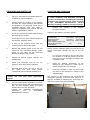
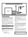
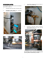
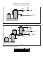
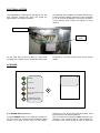
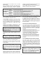
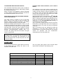
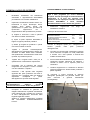
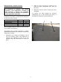
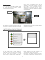
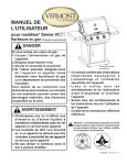
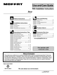
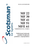
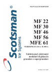
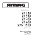
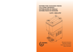
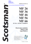
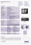
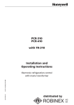
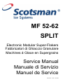
MF 52-62
SPLIT
Electronic Modular Super-Flakers
Fabbricatori di Ghiaccio Granulare
Machines á Glace en Supergrains
Service Manual
Manuale di Servizio
Manuel de Service
090144.03 - REV. 02-2004
TABLE OF CONTENTS – INDICE – TABLE DES MATIERES
ENGLISH
♦
♦
♦
♦
♦
♦
♦
♦
♦
♦
♦
♦
♦
♦
♦
Table of Contents.......................................................................................................................... Page 1
Specifications......................................................................................................................................... 2
Technical Specifications.......................................................................................................................... 2
Unpacking and Inspection....................................................................................................................... 3
Location and Levelling............................................................................................................................ 3
Typical Installation on Refrigerant Plant ................................................................................................... 4
Electrical Connections ............................................................................................................................ 4
Water Supply and Drain Connections ...................................................................................................... 4
Refrigerant System................................................................................................................................. 5
Refrigerant System Scheme.................................................................................................................... 6
Electrical System ................................................................................................................................... 7
PC Board and sensors............................................................................................................................ 7
Spare Parts............................................................................................................................................ 9
Wiring Diagram MF 52 .......................................................................................................................... 24
Wiring Diagram MF 62 .......................................................................................................................... 25
ITALIANO
♦
♦
♦
♦
♦
♦
♦
♦
♦
♦
♦
♦
♦
♦
♦
Indice .........................................................................................................................................Pagina 1
Specifiche.............................................................................................................................................. 2
Specifiche tecniche................................................................................................................................. 2
Disimballaggio ed Ispezione.................................................................................................................. 10
Posizionamento e Livellamento............................................................................................................. 10
Istallazione Tipica su un Impianto Frigorifero.......................................................................................... 11
Collegamenti Elettrici............................................................................................................................ 11
Alimentazione Idrica e Scarico Acqua .................................................................................................... 11
Circuito Frigorifero................................................................................................................................ 12
Schema del Circuito Frigorifero ............................................................................................................. 13
Circuito Elettrico................................................................................................................................... 14
Scheda Elettronica e Sensori ................................................................................................................ 14
Parti di Ricambio.................................................................................................................................. 16
Schema Elettrico MF 52........................................................................................................................ 24
Schema Elettrico MF 62........................................................................................................................ 25
FRANCAIS
♦
♦
♦
♦
♦
♦
♦
♦
♦
♦
♦
♦
♦
♦
Table des matieres ................................................................................................................................. 1
Specifications......................................................................................................................................... 2
Specificatrions techniques....................................................................................................................... 2
Emplacement et mise à niveau.............................................................................................................. 17
Installation Frigorifique Traditionnelle..................................................................................................... 18
Raccordement électrique ...................................................................................................................... 18
Arrivée d’eau et vidange ....................................................................................................................... 18
Equipement frigorifique ......................................................................................................................... 19
Schema de Systeme Frigorifique........................................................................................................... 20
Circuit électrique................................................................................................................................... 21
Carte de Regulation Electronique.......................................................................................................... 21
Pièces de rechange.............................................................................................................................. 23
Schema Electrique MF 52 ..................................................................................................................... 24
Schema Electrique MF 62 ..................................................................................................................... 25
SPECIFICATIONS – SPECIFICHE - SPECIFICATIONS
405
120
830
FRONT VIEW
VISTA LATERALE
VUE DE FACE
VUE DE COTE
535
POWER CORD
CAVO ELETTR.
ALIMENTATION
660
REAR VIEW
FRONT SIDE
TOP VIEW - VISTA DALL’ALTO
VUE DE DESSUS
VISTA POSTERIORE
WATER INLET ¾”
INGR. ACQUA ¾”
ENTREE EAU ¾”
MF 62
ONLY
SOLO
SEULEMENT
SIDE VIEW
VISTA FRONTALE
PANNELLO
FRONTALE
VUE ARRIERE
½” MF 52
5/8” MF 62
REFR. OUTLET
USCITA REFR.
SORTIE REFR.
3/8”
REFR. INLET
INGR. REFR.
ENTREE REFR.
FACADE
ICE DISCHARGE OPENINGS
APERTURE SCARICO GHIACCIO
DESCENTES DE GLACE
98
MF 62
ONLY
SOLO
SEULEMENT
245
180
WATER DRAIN
SCARICO ACQUA
VIDANGE
465
70
TECHNICAL SPECIFICATIONS – SPECIFICHE TECNICHE
SPECIFICATIONS TECHNIQUES
MODEL
MODELLO
MODELE
VOLTAGE
TENSIONE
VOLTAGE
AMPS
AMPERE
AMPS
MF 52 S
230/50-60/1
0.7
MF 62 S
230/50-60/1
1.4
POWER
POTENZA
PUISSANCE
FUSE
FUSIBILE
FUSIBLE
REFRIGERATION REQUIREMENT
POTENZA FRIGORIFERA RICHIESTA
PUISSANCE FRIGORIFIQUE
WATER CONSUMPTION
CONSUMO ACQUA
CONSOMMATION D’EAU
Watts
A
at/a –16ºC – Watts (Kcal/hr)
l/24 hrs
200
10
2325 (2000)
600
400
10
4650 (4000)
1200
2
UNPACKING AND INSPECTION
LOCATION AND LEVELLING
1.
Call your authorised SCOTSMAN Distributor
or Dealer for proper installation.
2.
Visually inspect the exterior of the packing
and skid. Any severe damage noted should
be reported to the delivering carrier and a
concealed damage claim form filled in
subject to inspection of the contents with the
carrier's representative present.
WARNING. This Modular Superflaker is designed
for indoor installation only. Extended periods of
operation at temperature exceeding the following
limitations will constitute misuse under the terms
of the SCOTSMAN Manufacturer's Limited
Warranty resulting in LOSS of warranty coverage.
3.
1.
in
the
selected
Criteria for the selection of location include:
a) Cut and remove the plastic strip securing
the carton box to the skid.
MIN
MAX
Air temperature
10°C (50°F)
40°C (100°F)
Water temperature
5°C (40°F)
35°C (90°F)
Water pressure
1 bar (14 psi) 5 bars (70 psi)
Electr. voltage variations from
voltage rating specified
-10%
+10%
on nameplate
b) Cut open the top of the carton and remove
the polystyre protection sheet.
c) Pull out the polystyre posts from the
corners and then remove the carton.
4.
Position the machine
permanent location.
Service access: adequate space must be left for all
service connections through the rear of the ice
maker.
Remove the front/top panel of the unit and
inspect for any concealed damage. Notify
carrier of your claim for the concealed
damage as stated in step 2 above.
1.
Lay out on the storage bin top the plan of the
ice machine as it will be located on the bin
and cut one or two openings according to the
Ice Maker model.
5.
Remove all internal support packing and
masking tape.
6.
Check that refrigerant lines do not rub
against or touch other lines or surfaces.
2.
Install the Modular Superflaker on the
storage bin pay attention to match the ice
chute/s with the Bin Top opening/s.
7.
See data plate on the rear side of the unit
and check that local main voltage
corresponds with the voltage specified on it.
3.
Level the Ice Maker in both the left to right
and front to rear directions by means of the
adjustable legs.
CAUTION. Incorrect voltage supplied to the
icemaker will void your parts replacement
program.
8.
The machine is also equipped with pre-pounched
rectangular openings on the left side panel so to
have the possibility to discharge the ice through the
side of the machine (not recommended).
Cut the manufacturer's registration card from
the back cover page of the User Manual and
fill-in all parts including: Model and Serial
Number taken from the data plate.
Forward the completed self-addressed
registration
card
to
SCOTSMAN
EUROPE/Frimont factory.
3
TYPICAL INSTALLATION ON A REFRIGERANT PLANT
HAND DISCONNECT
SWITCH
WATER
VALVE
WATER
FILTER
MF 52-62
POWER
WATER INLET
ICE MAKER
REFR. INLET
REFR. OUTLET
WATER DRAIN
ELECTRICAL CONNECTIONS
HAND SERVICE
VALVE
Since water is the most important single ingredient in
producting ice you cannot emphasize too much the
three items listed above.
Low water pressure, below 1 bar may cause
malfunction of the ice maker unit.
Water containing excessive minerals will tend to
produce scale build-up on the interior parts of the
water system while too soft water (with too lo
contents of mineral salts), will produce a very hard
flaker ice.
See data plate for current requirements to determine
wire size to be used for electrical connections. All
SCOTSMAN icemakers require a solid earth wire.
All SCOTSMAN ice machines are supplied from the
factory completely pre-wired and require only
electrical power connections to the wire cord
provided at the rear of the unit.
Make sure that the ice machine is connected to its
own circuit and individually fused (see data plate for
fuse size).
The maximum allowable voltage variation should not
exceed -10% and + 10% of the data plate rating. Low
voltage can cause faulty functioning and may be
responsible for serious damage to the overload
switch and motor windings.
WATER SUPPLY
Connect the 3/4" GAS male of the water inlet fitting,
using the food grade flexible tubing supply with the to
unit the cold water supply line with regular plumbing
fitting and a shut-off valve installed in an accessible
position between the water supply line and the unit.
If water contains a high level of impurities, it is
advisable to consider the installation of an
appropriate water filter or conditioner.
NOTE. All external wiring should conform to national,
state and local standards and regulations.
Check voltage on the line and the ice maker's data
plate before connecting the unit.
WATER DRAIN
The recommended drain tube is a plastic or flexible
tube with 18 mm (3/4") I.D. which runs to an open
trapped and vented drain. When the drain is a long
run, allow 3 cm pitch per meter (1/4" pitch per foot).
The ideal drain receptacle is a trapped and vented
floor drain.
WATER SUPPLY AND DRAIN CONNECTIONS
GENERAL
When choosing the water supply for the ice flaker
consideration should be given to:
NOTE. The water supply and the water drain must be
installed to conform with the local code. In some case
a licensed plumber and/or a plumbing permit is
required.
a) Length of run
b) Water clarity and purity
c) Adequate water supply pressure
4
REFRIGERANT SYSTEM
4
Thermostatic expansion valve (Flica TMVX ø
2.0 mm - 2 pcs on MF 62)
5
Refrigerant evaporating pressure regulating
valve (Danfoss KVP 12 on MF 52 and
Danfoss KVP 22 on MF 62)
The refrigerant system of the new MF 52-62 Flakers
Split versions consists off:
1
Refrigerant inlet flared male connection (3/8“)
2
Refrigerant outlet flared male connection
(1/2“ MF 52 and 5/8” MF 62)
3
Liquid solenoid valve
The refrigerant system is supplied completely sealed
with two copper caps located on the flared nuts and
pre-charged with a limited quantity of R404a.
5
REFRIGERANT SYSTEM SCHEME
LIQUID
SOLENOID
VALVE
THERMOSTATIC
EXPANSION
VALVE
REFRIGERANT
INLET - LIQUID
KVP
REFRIGERANT
OUTLET - GAS
MF 52
THERMOSTATIC
EXPANSION
VALVE
LIQUID
SOLENOID
VALVE
REFRIGERANT
INLET - LIQUID
KVP
REFRIGERANT
OUTLET - GAS
THERMOSTATIC
EXPANSION
VALVE
MF 62
Recommended refrigerant copper tubes size are:
MF 52
MF 62
LIQUID LINE
GAS LINE
10 mm-3/8”
10 mm-3/8”
12 mm-1/2”
16 mm-5/8”
6
ELECTRICAL SYSTEM
The Superflakers models MF 52 and MF 62 use, like
their compact versions MF 51/61, the typical PC
Board used in our Flaker machines.
On model MF 62, in addition to the Main PC Board, it
is also used the interface PC Board of the model MF
61 so to have the possibility to control the operation
of two different drive motors and optical ice level
controls.
INTERFACE PC BOARD
TERMINAL
BOARD
On the back side of the unit there is a open hole
(plugged with a rubber cup) to electrically connect the
PC Board to a remote control (Timer and/or remote
switch)
PC BOARD
POWER
BIN FULL
NO WATER
TOO LOW AMBIENT TEMP
STAND BY
WRONG ROTATION
TOO HI EVAP TEMP
P.C. BOARD (Data processor)
protected by two fuses, integrated with three small
jumpers and an I/R adjusting trimmer.
Also it consists of five aligned LEDS monitoring the
operation of the machine and of input terminals for
the leads of the sensor probes as well as input and
The P.C. BOARD, fitted in its plastic box located in
the front of the unit, consists of two separated printed
circuits one at high and the other at low voltage,
7
output terminals for the leads of the ice maker
electrical wires.
The P.C. BOARD is the brain of the system and it
elaborates, through its micro processor, the signals
received from the sensors in order to control the
GREEN LIGHT
YELLOW LIGHT (steady)
(bleanking)
YELLOW LIGHT
RED LIGHT
(steady)
(bleanking)
YELLOW LIGHT (steady)
(bleanking)
operation of the different electrical components of the
ice maker (gear motor, solenoid valve, etc.).
The five LEDS, placed in a row in the front of the P.C.
BOARD, monitor the following situations:
Unit under electrical power
Unit shut-off at full storage bin
Unit in shut-off procedure at full storage bin (I/R beam cutted)
Unit shut-off due to a too low-water level into float tank
Unit shut-off due to a too low-ambient temperature <+1°C
3 minutes delay time at start up
Unit shut-off due to the wrong rotation direction of gear motor
Unit shut-off due to the too low speed of gear motor
Unit shut-off due to a too hi-evaporating temp. >-1°C after 10 min of operation
The P.C. Board has also three small jumpers which
work as described in details here below.
two ice bin level light controls transmitting it to the
P.C. Board for the control of the unit operation.
In practical terms the Interface P.C. Board is
equipped by four INLET sockets (two for the drive
motor rotation/direction sensors and two for the ice
level controls) and two OUTLET plugs connected to
the unit P.C. Board.
The JP1 (TEST) is used ONLY on the factory allows
to make a rapid auto-diagnosis (when plug in) of the
P.C. Board outputs to liquid solenoid valve and gear
motor, by energising them in rapid sequence (2
seconds) one at the time, to make sure of their
operation.
EVAPORATOR TEMPERATURE SENSOR
DURING THE AUTOMATIC OPERATION OF THE
ICE MAKER THE JUMPER MUST BE REMOVED.
The evaporator sensor probe is inserted into its tube
well, which is welded on the evaporator outlet line, it
detects the temperature of the refrigerant on the way
out from the evaporator and signals it by supplying a
low voltage current flow to the P.C. Board MicroProcessor.
According to the current received, the microprocessor let the ice maker to continue its operations.
In case the evaporating temperature, after 10
minutes from the unit start-up, does not go below 1°C (30°F) due to shortage of refrigerant in the
system or due to the excessive condensing
temperature, the evaporator sensor signal reaching
the microprocessor is such to stop immediately the
unit operation, with the 5th Warning YELLOW LED
that blinks.
WARNING.
This
auto-diagnosis
must
be
performed in the shortest possible time in order
to avoid frequent starts and stops of the electrical
components which may cause damages to their
windings and controls.
The JP2, when closed, allows the skipping of the 3
minutes delay period at every start-up of the Ice
Maker.
NOTE. To prevent that the unit be subject to starts
and stops in rapid sequence it is strongly
recommended to keep these contacts always open..
FLOAT RESERVOIR WATER SENSOR SYSTEM.
The JP3 on model MF 52-62 is not used and can be
open or closed without any operating problem.
This sensor system consist of two small stainless
steel rods vertically fitted on the inner face of the
reservoir cover and electrically connected to the low
voltage circuit of the P.C. Board. When the cover of
the reservoir is positioned in its place the tips of both
the rods dip into the reservoir water and detects and
signals its presence by making use of its electrical
resistance.
The I/R trimmer is used to modify a little the current
transmitted by the Infrared Optical Ice Level Control
to the PC Board.
NOTE. When change the setting, it is IMPERATIVE
to check up the correct operation of the Ice Level
Control filling up the vertical ice chute/s with flaker ice
till it break the Infrared beam between transmitter and
nd
receiver (2 YELLOW LED blinking). DO NOT USE
HANDS.
NOTE. In the event of shortage of water in the
reservoir or, in case the water used is too soft (demineralized) to cause greater resistance to the
current flow (conductivity lower than 30 µS) this
sensor system causes the shutoff of the machine.
In this situation the YELLOW LED will glow to warn
of the machine shutoff and the reason why.
INTERFACE P.C. BOARD (Only on MF 62 Model)
Used only on MF 62 model, it allows to elaborate the
signal received from one of the two gear motor
rotation/direction sensors as well as from one of the
8
CONDENSER TEMPERATURE SENSOR
ICE BIN LEVEL LIGHT CONTROL (Two on MF 62
Model)
The condenser temperature sensor probe, located on
the frame of the unit, is used (on MF 52/62) to detect
the ambient temperature.
When it is below +1°C (33°F) the signal transmitted
to the PC Board is equivalent to keep the unit OFF till
the ambient temperature rise up to +5°C.
The electronic ice bin level control, located into the
ice chute (one in each of the two ice chutes on MF 62
model), has the function to stop the operation of the
ice machine when the light beam between the light
source and the sensor gets interrupted by the flake
ice which accumulates in the chute.
ND
When the light beam is interrupted the 2 YELLOW
LED located in the front of the P.C. BOARD starts to
blink. In case the light beam gets interrupted for as
longer as 10 seconds, the ice machine stops with the
glowing-up of the 2nd YELLOW LED (steady) to
monitor the full ice bin situation.
The 10 seconds of delay prevents that any minimum
interruption of the light beam due to the regular ice
chuting through the ice chute may stop the operation
of the unit.
After 10 seconds of the ice scooped out (with the
resumption of the light beam between the two
infrared sensor of ice level control) the ice machine
resume its operation with the simultaneous
extinguishing the 2nd YELLOW LED.
GEAR MOTOR ROTATION AND SPEED SENSOR
(Two on MF 62 Model)
This safety device is housed on top of the Drive
Motor (one per each motor on MF 62 model) and
detects - based on Hall Effect principle - the rotating
speed and rotating direction of the drive Motor.
Should the rotating speed drop below 1300 r.p.m. the
magnitude measured by this device is such to signal
to the microprocessor to stop the unit and light-up the
YELLOW LED. About the same reaction occures
when the drive motor will tend to rotate in the wrong
direction (counterclockwise) situation that, if it
occures, will greatly affect all the freezer and gear
reducer components.
NOTE. To restart the unit after the shutoff caused by
this safety device, it is necessary first to eliminate the
cause that has generated the intervention of the
device and switch OFF and ON the power line main
disconnect switch.
SPARE PARTS
The only spare parts typical of the new MF 52/62
Split versions are listed in the following chart.
All the service parts used on gear reducer as well as
in the freezer assy are exactly the same of the
standard model MF 51/61.
MF 52
Liquid solenoid valve body
Liquid solenoid valve coil
Thermostatic expansion valve body
Thermostatic expansion valve nozzle
Refrigerant evaporating pressure regulating valve
Contactor
9
620306
620306
620427
620427
620454
630119
07
48
00
08
01
02
MF 62
620306
620306
620427
620427
620454
630119
07
48
00
08
00
02
DISIMBALLAGGIO ED ISPEZIONE
1.
Richiedere l’assistenza del Distributore
autorizzato o rappresentante SCOTSMAN
per effettuare una corretta installazione.
2.
Ispezionare visivamente l’imballo esterno e il
basamento in legno. Qualunque danno
evidente
deve
essere
riferito
allo
spedizioniere; in questo caso, procedere ad
ispezionare
l’apparecchio
con
il
rappresentante dello spedizioniere presente
3.
POSIZIONAMENTO E LIVELLAMENTO
ATTENZIONE. Questo fabbricatore di ghiaccio
NON è stato progettato per essere installato
all’aperto. Periodi prolungati di funzionamento a
temperature al di fuori dei seguenti limiti
costituiscono uso improprio secondo i termini di
garanzia
SCOTSMAN
e
fanno
decadere
automaticamente il Vostro diritto alla garanzia.
1.
nel
luogo
di
I criteri per la sua scelta sono:
a) Tagliare e rimuovere i nastri in plastica
che fissano l’imballo al basamento.
Temperatura ambiente
Temperatura acqua di alimentazione
Pressione dell’acqua
Variazioni della tensione di rete dal valore
indicato sulla targhetta
b) Aprire la parte superiore dell’imballo e
togliere il foglio di polistirolo protettivo.
c) Sfilare gli angolari di polistirolo e quindi
rimuovere l’imballo di cartone.
4.
Posizionare
l’apparecchio
installazione definitivo.
MIN
10°C
5°C
1 bar
MAX
40°C
35°C
5 bar
-10%
+10%
Lasciare un adeguato spazio per i collegamenti di
servizio
previsti
nella
parte
posteriore
dell’apparecchio.
Togliere
il
pannello
frontale/superiore
dell’apparecchio ed ispezionare lo stesso per
accertare se abbia subito danni. Notificare
allo spedizioniere eventuali danni subiti come
riportato al precedente punto 2.
2.
Tracciare sul coperchio del contenitore la (pianta)
che la macchina occuperà una volta posizionata
e ricavare una o due aperture a seconda del
modello di fabbricatore.
3.
Porre il fabbricatore Modulare Supergranulare sul
contenitore facendo attenzione ad allineare i
condotti di scarico con le aperture poste sul
contenitore.
Livellare l’apparecchio in entrambe le direzioni
(anteriore-posteriore e destra-sinistra) mediante i
piedini regolabili.
5.
Togliere tutti i supporti interni usati per la
spedizione ed i nastri adesivi di protezione.
6.
Controllare che le tubazioni del circuito
refrigerante non sfreghino o siano a contatto
con altre tubazioni o superfici.
4.
Osservare i dati riportati sulla targhetta
applicata alla parte posteriore del telaio e
verificare che il voltaggio della rete elettrica
disponibile
corrisponda
a
quello
dell’apparecchio riportato sulla targhetta.
La macchina è inoltre provvista di aperture
rettangolari prestampate sul pannello sinistro per
poter
scaricare
il
ghiaccio
lateralmente
(sconsigliabile).
7.
ATTENZIONE.
Un
errato
voltaggio
dell’alimentazione
elettrica
annullerà
automaticamente il Vostro diritto alla garanzia.
8.
Compilare la cartolina di garanzia da
ritagliare dall'ultima di copettina del Manuale
d’Uso indicando sia il modello che il numero
di serie dell’apparecchio rilevandoli dalla
targhetta applicata al telaio.
Spedire la cartolina debitamente compilata
alla
SCOTSMAN
EUROPE/Stabilimento
Frimont.
10
IMPIANTO FRIGORIFERO – INSTALLAZIONE TIPICA
INTERRUTTORE A
DISINSERIMENTO MANUALE
VALVOLA
ACQUA
FILTRO
ACQUA
FABBRICATORE DI GHIACCIO
TENSIONE
INGRESSO ACQUA
MF 52-62
INGRESSO RAFFREDDAMENTO
SCARICO RAFFREDDAMENTO
SCARICO ACQUA
COLLEGAMENTI ELETTRICI
VALVOLA MANUALE
DI SERVIZIO
a) Lunghezza della tubazione
b) Limpidezza e purezza dell’acqua
c) Adeguata pressione dell’acqua di
alimentazione
Osservare la targhetta dell’apparecchio per stabilire,
in funzione dell’amperaggio indicato, il tipo e la
sezione del cavo da impiegare nei collegamenti
elettrici.
Tutti gli apparecchi SCOTSMAN vengono forniti
provvisti di cavi elettrici di collegamento e occorre
solo collegare la rete di alimentazione elettrica al
cavo posto sul retro dell’apparecchio.
Assicurarsi che il fabbricatore sia collegato al circuito
corretto e con fusibili adeguati, come indicato nella
targhetta di ogni singolo apparecchio.
La variazione massima di tensione non deve
superare del 10% (in eccesso o in difetto) il valore di
targa. Un basso voltaggio può causare un
funzionamento anomalo e può essere causa di seri
danni alle protezioni ed agli avvolgimenti elettrici.
Poiché l’acqua è il più importante ed unico
ingrediente per la fabbricazione del ghiaccio, non
bisogna in nessun caso trascurare i tre punti suddetti.
Una pressione dell’acqua di alimentazione inferiore
ad 1 bar può causare dei disturbi di funzionamento
nell’apparecchio.
L’impiego di acque troppo ricche di minerali tenderà
a produrre un accumulo di scaglie di ghiaccio
all’interno del circuito idraulico, mentre acque troppo
dolci (con un contenuto di sali minerali ridotto)
produrrà un ghiaccio in granuli molto duri.
ALIMENTAZIONE IDRAULICA
Collegare il raccordo da 3/4 di pollice maschio del
raccordo di ingresso acqua alla linea di
alimentazione idraulica (utilizzando il tubo in plastica
rinforzato del tipo alimentare atossico fornito con
l’apparecchio)
prevedendo
un
rubinetto
d’intercettazione nei pressi dell’apparecchio. Se
l’acqua di alimentazione è particolarmente ricca di
impurità, è consigliabile installare filtri o depuratori
appropriati.
NOTA. Tutti i collegamenti esterni devono essere
effettuati a regola d’arte in conformità con quanto
stabilito dalle leggi locali.
Prima di collegare il fabbricatore accertarsi ancora
una volta che il voltaggio dell’apparecchio,
specificato sulla targhetta, corrisponda al voltaggio
misurato.
ALIMENTAZIONE IDRAULICA E SCARICO
ACQUA
SCARICO ACQUA
Si consiglia di usare un tubo di scarico in plastica
rigida o flessibile con un diametro interno di 18 mm
(3/4”) che vada in un sifone aperto e ventilato.
Qualora il tubo di scarico abbia una lunghezza
PREMESSA
Nella
scelta
dell’alimentazione
idraulica
al
fabbricatore di ghiaccio granulare si deve tenere in
considerazione:
11
elevata, prevedere una pendenza di 3cm per ogni
metro di lunghezza.
Lo scarico ideale è un sifone a pavimento separato e
ventilato.
4
Valvola di espansione termostatica (Flica
TMVX ø 2.0 mm - 2 pezzi nel MF 62)
5
Valvola di regolazione della pressione di
evaporazione costante (Danfoss KVP 12 nel
MF 52 e Danfoss KVP 22 nel MF 62)
NOTA. I collegamenti di alimentazione e scarico
dell’acqua devono essere eseguiti in conformità alle
leggi locali. In alcuni casi è richiesto l’intervento di un
idraulico patentato e/o un’autorizzazione ad
effettuare il lavoro.
IMPIANTO REFRIGERANTE
L’impianto refrigerante dei nuovi Granulari MF 52-62
versione Split è costituito da:
1
Raccordo
maschio
refrigerante (3/8“)
2
Raccordo maschio filettato uscita refrigerante
(1/2“ MF 52 e 5/8” MF 62)
3
filettato
ingresso
Valvola solenoide liquido
L’impianto refrigerante viene fornito completamente
sigillato mediante due tappi di rame chiusi da
bocchettoni, e precaricato con una quantità limitata di
R404a.
12
SCHEMA IMPIANTO REFRIGERANTE
VALVOLA SOLENOIDE
VALVOLA
DI INGRESSO
TERMOSTATICA
LIQUIDO
DI ESPANSIONE
INGRESSO REFRIGERANTE
-LIQUIDO-
KVP
USCITA REFRIGERANTE
- GAS -
MF 52
VALVOLA DI
ESPANSIONE
TERMOSTATICA
VALVOLA SOLENOIDE
DI INGRESSO
LIQUIDO
INGRESSO REFRIGERANTE
-LIQUIDO-
KVP
USCITA REFRIGERANTE
- GAS VALVOLA DI
ESPANSIONE
TERMOSTATICA
MF 62
Per il passaggio di refrigerante, si consigliano tubi in rame con i diametri seguenti:
MF 52
MF 62
LINEA
LIQUIDO
10 mm - 3/8"
10 mm - 3/8"
LINEA
GAS
12 mm - 1/2"
16 mm - 5/8"
CIRCUITO ELETTRICO
I modelli Supergranulari MF 52 ed MF 62 utilizzano,
come le corrispondenti versioni compatte MF 51/61,
la scheda elettronica tipica delle nostre macchine
granulari.
Nel modello MF 62 oltre alla scheda elettronica
principale si utilizza anche la scheda elettronica
d’interfaccia già presente sul modello MF 61 così da
avere la possibilità di controllare il funzionamento di
due diversi motori e lettori ottici del livello ghiaccio
SCHEDA ELETTRONICA
DI INTERFACCIA
MORSETTIERA
Sul retro della macchina vi è un’apertura chiusa da
un tappo di gomma che può essere usata per
collegare l’alimentazione elettrica della scheda
elettronica ad un
interruttore remoto)
controllo
remoto
(timer
e/o
SCHEDA ELETTRONICA
APPARECCHIO IN TENSIONE
CONTENITORE PIENO
MANCANZA ACQUA
TEMP. AMB. < 1°C
3' ATTESA
SENSO ROTAZ. ERR/NO ROTAZ.
SOVRATEMP. EVAP.
SCHEDA ELETTRONICA (Microprocessore)
La SCHEDA ELETTRONICA, collocata in una
scatola in plastica posta nella parte frontale
dell’apparecchio, è composta da due circuiti stampati
separati, ad alta ed a bassa tensione, protetti da due
fusibili e integrati da tre piccoli spinotti e un
potenziometro di regolazione dell'Infrarosso. Inoltre in
essa si trovano cinque LEDS allineati che controllano
le operazioni della macchina ed i terminali di ingresso
per il collegamento dei sensori, così come i terminali
di ingresso e uscita per il collegamento dei
componenti elettrici della macchina.
La scheda elettronica è il cervello del sistema ed
elabora, attraverso il suo microprocessore, i segnali
ricevuti dai sensori al fine di controllare le operazioni
dei diversi componenti elettrici dell’apparecchio
(motoriduttore, valvola solenoide, ecc.).
LED VERDE
LED GIALLO
LED GIALLO
LED ROSSO
LED GIALLO
(fisso)
(lampeggiante)
(fisso)
(lampeggiante)
(fisso)
(lampeggiante)
I cinque LEDS, allineati sulla parte frontale della
scheda elettronica, controllano le seguenti condizioni:
Apparecchio sotto tensione
Arresto per contenitore ghiaccio pieno
Interruzione fascio luminoso Infrarosso lettore ottico ghiaccio
Arresto per livello acqua basso nella vaschetta
Arresto per temperatura ambiente bassa (<+1°C)
3 minuti di attesa all’avviamento
Arresto per senso di rotazione errato del motoriduttore
Arresto per velocità di rotazione troppo bassa del motoriduttore
Arresto per temperatura di evaporazione elevata (>-1°C) dopo 10 minuti
di funzionamento
La scheda elettronica ha inoltre 3 spinette che hanno
le seguenti funzioni.
rotazione dei motori che di uno dei due sensori livello
ghiaccio,
inviandoli
alla
scheda
elettronica
dell’apparecchio per la gestione del funzionamento.
In pratica, la scheda elettronica di interfaccia è dotata
di QUATTRO INGRESSI (due per i sensori di
rotazione e due per i sensori livello ghiaccio) e di
DUE USCITE collegate alla scheda principale.
Presa JP1 (TEST), usata solamente durante il
collaudo, consente di effettuare una rapida autodiagnosi sulle uscite della scheda elettronica alla
valvola solenoide ed al motoriduttore, alimentandoli
in rapida successione (2 secondi ciascuno) per
accertarsi del loro funzionamento.
SENSORE TEMPERATURA EVAPORATORE
DURANTE IL FUNZIONAMENTO IN AUTOMATICO
DELLA MACCHINA, QUESTA PRESA DEVE
AVERE I CONTATTI APERTI.
Il sensore temperatura evaporatore, posto all’interno
di un tubo porta bulbo saldato all’uscita del cilindro
evaporatore, rileva la temperatura del refrigerante
aspirato e la trasmette, mediante un segnale a bassa
tensione,
al
microprocessore
della
scheda
elettronica.
In funzione del segnale ricevuto, il microprocessore
dà o meno alla macchina il consenso a proseguire
nel funzionamento. Infatti, se dopo 10 min.
dall’avviamento la temperatura dell’evaporatore non
è inferiore a –1°C a causa della mancanza di
refrigerante
o
dell’eccessiva
temperatura
di
condensazione, il segnale che dal sensore
temperatura
evaporatore
raggiunge
il
microprocessore è tale da arrestare immediatamente
il
funzionamento
dell’apparecchio,
facendo
lampeggiare il 5° LED (GIALLO) di allarme.
WARNING. Questa auto-diagnosi deve essere
effettuata nel più breve tempo possibile, per
evitare frequenti arresti e ripartenze dei
componenti
elettrici
che
ne
potrebbero
compromettere il funzionamento.
La seconda presa JP2 serve per by-passare i 3
minuti di attesa ad ogni partenza.
Nota. Per evitare che la macchina sia soggetta a
frequenti partenze/arresti è raccomandato di tenere i
contatti sempre aperti.
La presa JP3, nel modello MF 52-62 non è usata e
può essere lasciata chiusa o aperta senza problemi
di malfunzionamento.
SENSORE LIVELLO ACQUA VASCHETTA
GALLEGGIANTE.
Questo sensore è composto da due barrette in
acciaio inossidabile fissate verticalmente alla parte
interna del coperchio e collegate elettricamente al
circuito a bassa tensione della scheda elettronica.
Quando il coperchio viene posizionato sulla
vaschetta, le estremità delle barrette risultano
immerse nell’acqua e segnalano la presenza di
quest’ultima alla scheda elettronica mediante un
flusso di corrente trasmesso dai sali minerali disciolti.
Il potenziometro I/R ha la funzione di variare la
resistenza elettrica del Lettore Ottico. Agendo su di
esso si può variare la corrente trasmessa alla scheda
elettronica.
Nota. Qualora sia variata la regolazione originale, è
IMPERATIVO testare il buon funzionamento del
Lettore Ottico con il ghiaccio prodotto. Questi, come
interrompe il fascio luminoso all'infrarosso, fa
lampeggiare il 2° LED GIALLO. NON USARE LE
MANI PER QUESTO TEST.
NOTA. In caso di mancanza d’acqua nella
vaschetta, o in caso di acqua troppo dolce
(demineralizzata) per poter fungere da conduttore di
elettricità (conducibilità inferiore a 30 µS) il sensore
provocherà l’arresto del produttore di ghiaccio,
segnalato dall’accensione del LED GIALLO
corrispondente.
SCHEDA ELETTRONICA DI INTERFACCIA (Solo
nel modello MF 62)
Usata solo nel modello MF 62, essa consente di
elaborare i segnali sia di uno dei due sensori di
15
SENSORE TEMPERATURA CONDENSATORE
SISTEMA OTTICO DI CONTROLLO
GHIACCIO (Due nel Modello MF 62)
Il bulbo del sensore temperatura condensatore, posto
sul telaio della macchina, è usato (negli MF 52/62)
per rilevare la temperatura ambiente.
Quando quest’ultima scende sotto +1°C il segnale
trasmesso alla scheda elettronica causa l’arresto
dell’apparecchio fino a quando la temperatura non
sia risalita oltre i +5°C.
LIVELLO
Il sistema ottico per il controllo del livello del ghiaccio,
posto nel condotto di scarico del ghiaccio (uno per
ogni condotto nel modello MF 62), ha la funzione di
arrestare il funzionamento del produttore quando il
fascio luminoso tra la sorgente ed il sensore viene
interrotto dal ghiaccio granulare che si accumula nel
condotto.
Quando il fascio luminoso viene interrotto, il 2° LED
GIALLO lampeggia; nel caso in cui l’interruzione sia
superiore ai 10 secondi, il funzionamento della
macchina si arresta ed il SECONDO LED GIALLO si
accende in continuo, ad indicare lo stato di
contenitore pieno.
I 10 secondi di ritardo evitano che ogni minima
interruzione del fascio luminoso, dovuta alla normale
caduta del ghiaccio attraverso il condotto, possa
arrestare il funzionamento del fabbricatore di
ghiaccio.
Trascorsi 10 secondi dalla rimozione del ghiaccio
(ripristino del raggio luminoso tra i due lettori ottici del
sensore) il LED GIALLO si spegne facendo
lampeggiare simultaneamente il LED ROSSO dei 3
minuti di attesa.
SENSORE VELOCITA’ E ROTAZIONE MOTORE
RIDUTTORE (Due nel Modello MF 62)
Questo dispositivo di sicurezza è alloggiato nella
parte superiore del motore e rileva – sfruttando il
principio dell’Effetto Hall) – la velocità ed il verso di
rotazione del motore.
Quando la velocità di rotazione scende al di sotto dei
1300 giri/min. il segnale che il sensore rileva e
trasmette al microprocessore è tale da causare
l’arresto immediato dell’apparecchio e l’accensione
del LED GIALLO corrispondente. Lo stesso accade
quando il motore tende a girare nel verso opposto
(antiorario), cosa che potrebbe provocare danni ai
componenti dell’evaporatore e del motoriduttore.
NOTA. Per riavviare il fabbricatore dopo l’arresto
dovuto a questo dispositivo di sicurezza, è prima di
tutto necessario eliminare la causa che ne ha
provocato l’intervento, quindi togliere e ripristinare
l’alimentazione elettrica.
PARTI DI RICAMBIO
Tutte le parti utilizzate sia nel motoriduttore che
nell’assieme freezer sono esattamente le stesse dei
modelli standard MF 51/61.
Le uniche parti caratteristiche delle nuove versioni
MF 52/62 Split sono riportate nella tabella seguente.
MF 52
Valvola solenoide di liquido (corpo)
Valvola solenoide di liquido (bobina)
Valvola di espans. termostatica (corpo)
Valvola di espans. termostatica (ugello)
Refrigerant evaporating pressure valve
Contattore
16
620306
620306
620427
620427
620454
630119
07
48
00
08
01
02
MF 62
620306
620306
620427
620427
620454
630119
07
48
00
08
00
02
Emplacement et mise à niveau
Attention: Cette machine modulaire est prévue
pour fonctionner à l’intérieur. Une période
d’utilisation à des températures excédant les
limites prescrites ci dessous sera considérée
comme une mauvaise utilisation et entraînera la
perte de la garantie constructeur.
MINIMUM
10°
5°
1 Bar
-10%
MAXIMUM
40°
35°
5 Bar
+10%
Pour le voltage prendre en compte la valeur spécifiée
sur la plaque du constructeur
Accessibilité pour le service technique: un espace
adéquat doit être laissé pour toutes les connections à
l’arrière de la machine.
1.
Mettre en place la machine en s’assurant que la
chute de glace corresponde bien avec les
découpes.
3.
Effectuer la mise à niveau au moyen des vérins
de réglage
La machine est aussi équipée de panneaux
prédécoupés sur le côté gauche afin d’avoir la
possibilité de décharger la glace latéralement.
Positionner la machine à l’emplacement sélectionné
à partir des critères suivants:
Temperature d’air
Temperature d’eau
Pression d’eau
Variation du voltage
2.
Positionner sur la cabine de stockage ou sur le
toit de la chambre froide le plan gabarit de la
machine afin d’effectuer la (MF 52) ou les
découpes (MF 62) nécessaires aux chutes de
glace.
17
INSTALLATION FRIGORIFIQUE TRADITIONNELLE
HAND DISCONNECT
SWITCH
WATER
VALVE
WATER
FILTER
MF 52-62
POWER
WATER INLET
ICE MAKER
REFR. INLET
REFR. OUTLET
WATER DRAIN
Raccordement électrique
HAND SERVICE
VALVE
Compte tenu de l’importance de l’eau dans la
fabrication de la glace, nous mettons l’accent sur les
trois points ci dessus.
Une faible pression d’eau inférieure à 1 bar entraîne
un mauvais fonctionnement
De l’eau très minéralisée va créer des dépôts à
l’intérieur du circuit d’eau, tandis que de l’eau trop
douce produira une glace très dure.
Contrôler la plaque du constructeur pour déterminer
la section des câbles électriques pour la connection.
Toutes les machines Scotsman nécessitent un
raccordement à la terre.
Les machines Scotsman sont complètement
précablées d’origine et nécessitent uniquement le
raccordement à la puissance sur le bornier à l’arrière
de l’unité.
S’assurer que la machine soit connectée à son
propre circuit avec protection individuelle (calibrage
des fusibles sur la plaque du constructeur). La
variation maximale de la tension ne doit pas excéder
+ ou – 10% de la valeur indiquée.
Un faible voltage peut entraîner un mauvais
fonctionnement et être responsable de dommages
liés à une surintensité sur les composants
électriques.
Contrôler que le voltage de la ligne corresponde bien
à celui de la plaque constructeur avant toute mise en
route.
Arrivée d’eau
Connecter le raccord ¾ mâle de l’entrée d’eau , en
utilisant le flexible
alimentaire fourni avec la
machine, sur le robinet d’arrêt de la ligne d’arrivée
d’eau froide qui doit être accessible facilement.
Si l’eau contient des impuretés il est nécessaire de
prévoir l’installation d’un systême de filtration
adéquat.
Vidange
Nous recommandons l’utilisation d’un flexible de
diamètre intérieur 18 mm à raccorder sur une
vidange ouverte. Lorsque la vidange est éloignée
vous devez prévoir une pente de 3 cm par mètre.
Arrivée d’eau et vidange
Généralités
Pour choisir l’alimentation d’eau de la machine vous
devez prendre en compte les points suivants :
a) Longueur de la tuyauterie
b) Qualité et pureté de l’eau
c) Pression d’eau adéquate
18
Equipement frigorifique
4.
Détendeur thermostatique Flica TMVX ∅ 2.0
mm, 2 sur MF 62
5.
Vanne à pression évaporation constante Danfoss
KVP 12 sur MF 52 et Danfoss KVP 22 sur MF 62
L’équipement frigorifique des nouvelles MF 52-62 est
composé de:
1.
Raccord flare 3/8” mâle entrée du liquide
2.
Raccord flare (1/2” MF 52 - 5/8” MF 62)
3.
Electrovanne liquide
Le circuit frigorifique est hermétiquement fermé par
deux capsules de cuivre vissées par les écrous des
raccords flare et pré-chargé avec du gaz réfrigerant
R 404 A.
19
SCHEMA DE SYSTEME FRIGORIFIQUE
DETENDEUR
THERMOSTATIQUE
VANNE
SOLENOID
LIQUIDE
REFRIGERANT
ENTREE - LIQUIDE
KVP
REFRIGERANT
SORTIE - GAS
MF 52
DETENDEUR
THERMOSTATIQUE
VANNE
SOLENOID
LIQUIDE
REFRIGERANT
ENTREE - LIQUIDE
KVP
REFRIGERANT
SORTIE - GAS
DETENDEUR
THERMOSTATIQUE
MF 62
Dimensions des tuyaux en cuivre frigorifiques:
MF 52
MF 62
Liquide
10 mm - 3/8"
10 mm - 3/8"
20
Gas
12 mm - ½"
16 mm - 5/8"
Circuit électrique
Sur la MF 62 en complément de la carte de
régulation est aussi utilisée l’interface du modèle
Compact MF 61, qui offre la possibilité de contrôler
différemment le fonctionnement des deux moteurs
d’entraînement et des deux cellules photo optiques
de niveau de glace.
Les modèles Split MF 52 et MF 62 utilisent, comme
les modèles Compacts MF 51 et MF 61, la même
carte de régulation électronique.
INTERFACE
BORNIER
Sur l’arrière de la machine se trouve une trou avec
un capouchin en caoutchouc permettant de raccorder
l’alimentation de la carte à une commande à distance
(minuterie ou interrupteur)
CARTE DE REGULATION ELECTRONIQUE
MACHINE SOUS TENSION
CABINE PLAIN
MANQUE EAU
TEMP. AMB. < 1°C
3' ATTENTE
ROTATION INVERSE/NO ROTAT.
TEMP. EVAP. ELEVEE
La carte, insérée dans sa coque plastique et
positionnée en façade de la machine, est constituée
de deux circuits imprimés séparés, un en haute
tension, l’autre en basse tension, protégés par 2
fusibles, intégrée par trois petit "jumpers" et un
potentiometre de regulation de l'Infrarouge.
Elle possède 5 Leds alignées contrôlant les fonctions
de la machine et les ports de connections pour les
21
sondes de régulation ainsi que la barette de
connections pour la puissance.
La carte est le cerveau du système et élabore à
travers son micro processeur, les signaux reçus de la
part des sondes afin de contrôler les différents
composants électriques de la machine à glace
Led Verte:
Led jaune :
Led jaune :
Led rouge:
Led jaune :
allumage fixe:
allumage clignotant:
allumage fixe:
allumage clignotant:
allumage fixe:
allumage clignotant:
(moteur
etc…).
d’entraînement,
Les 5 Leds
suivantes:
alignées
vanne
solenoid
contrôlent
les
liquide,
situations
Sous tension
Cabine de stockage pleine
Coupure faiscea infrarouge sonde optique niveau glace
Sécurité manque d’eau
Température ambiante <+1°C
Temporisation de 3 minutes au démarrage
Rotation en sens inverse du moteur ou vitesse trop basse
Température d’évaporation >-1°C après 10 minutes
Interface (Seulement dans l'MF 62)
Micro interrupteurs
Utilisée seulement sur le modèle MF 62, elle permet
la réception des signaux électriques en provenance
des capteurs de contrôle de vitesse/sens de rotation
des moteurs d’entraînement ainsi que ceux en
provenance des cellules de contrôle de niveau de
glace.
En effet l’interface est équipée de quatre bornes
d’arrivée (deux pour la vitesse/sens de rotation des
moteurs et deux pour le contrôle du niveau de glace)
et de deux bornes de sortie reliées à la carte de
régulation.
La carte à trois petit "jumpers" avec les fonctions
suiventes:
Le JP1 (TEST) est utilisé seulement pendante l'essai
de la machine pour faire un rapide auto diagnostic
des sorties de la barette de connection de la carte
vers la vanne solénoïde et le moteur du réducteur, en
les alimentant 2 secondes chacun pour le contrôle de
leur bon fonctionnement.
PENDANT
LE
FONCTIONNEMENT
AUTOMATIQUE DE LA MACHINE, CETTE
"JUMPER" DOIT ETRE TOUJOURS OUVERTE
Sonde de température d’évaporation
La sonde est insérée dans un tube soudé sur la
sortie de l’évaporateur, elle détecte la température du
réfrigérant à la sortie de l’évaporateur et en informe
la carte de régulation par un retour de courant à
basse tension
En fonction du courant reçu le micro processeur
autorise la fabrication de la glace.
Dans l’hypothèse ou la température d’évaporation
n’atteint pas –1° au bout de 10 minutes, le micro
processeur arrête le fonctionnement de la machine et
allume la cinquième Led jaune en clignotant.
ATTENTION: Cette opération doit être effectuée
dans un délai bref afin d’éviter les courts cycles.
La deuxième prise (jumper) JP2 est utilisé pour bypasser les trois minutes d'attente a chaque
demarrage.
Note. Pour eviter a la machine fréquant
marche/arrete, il est imperatif avoir les contacts
toujours ouvertes.
Sonde de niveau d’eau dans le réservoir
La troisieme prise (JP3) n'est pas utilisée dans les
modeles MF 52-62 et peut etre fermé ou ouverte
sans problemes de malfunctionnement de la
machine.
Cette sonde fonctionne avec deux tiges en inox
verticales fixées sur le couvercle du réservoir et
reliées électriquement au circuit basse tension du
micro processeur.
Quand le couvercle du réservoir est en place les
deux tiges plongent dans l’eau et détectent sa
présence en utilisant sa résistivité.
Le potentiometre I/R est utilisé pour changer la
courant electrique transmis par la sonde optique a la
carte.
Note. Dans le cas le reglage d'origine a ete modifié, il
est IMPERATIF de verifier le bonne fonctionnement
de la sonde optique avec la glace produì par la
machine.
Comme le faisceau est coupé par la glace, le 2eme
temoin joune doit clignoté. NE PAS UTILISE' LES
MAINS.
NOTA: En cas de manque d’eau dans le réservoir
ou, en cas d’utilisation d’eau trop déminéralisée ou
trop douce pour assurer la conduction du courant
entre les tiges (conductivité inférieure à 30 micro
siemens), le micro processeur arrête la machine et
allume la troisième Led jaune.
22
Sonde de température condenseur/ambiante
NOTA : pour redémarrer l’unité après l’arrêt causé
par ces sécurités, il est nécessaire d’éliminer la
cause qui a généré l’intervention du dispositif avant
de debrancher et rebrancher de nouveau la machine
a la prise electrique.
Quand la température ambiante est inférieure à +1°
le microprocesseur arrête la machine et allume la
quatrième Led rouge, il n’autorisera le redémarrage
qu’à partir de +5°.
Détecteur optique de niveau de glace
Dispositif de contrôle de vitesse et de sens de
rotation du motoréducteur
La cellule photo électrique (2 pour la MF 62) située à
l’extérieur de la chute de glace détecte la présence
de glace accumulée devant le faisceau optique et
arrête la machine en allumant la deuxième Led
jaune.
Quand le faisceau est interrompu la Led Jaune
Cabin Plain clignote; dans le cas ou il reste
interrompu pendant plus de 10 secondes la machine
s’arrête avec le même Led Jaune allumé fixe.
Le délai de 10 secondes évite que le faisceau soit
coupé par la chute permanente des grains de glace.
Lors du prélèvement de la glace, le niveau de glace
s’abaisse afin de rétablir le faisceau optique de la
cellule photo électrique. Après 10 secondes en
éteignant la deuxième Led jaune s'éteign et
commence a clignoté le Led Rouge de 3' d'attente.
Ce dispositif de sécurité est monté sur la partie
supérieure du moteur (2 pour la MF 62) et détecte
grâce au principe de l’effet Hall la vitesse et le sens
de rotation.
Lorsque la vitesse est inférieure à 1300 tours minute,
le microprocesseur arrête la machine et allume la
cinquième Led jaune.
Il en est de même quand le moteur tente de démarrer
dans le mauvais sens (sens inverse des aiguilles
d’une montre) suite à une prise en glace totale de la
vis sans fin, qui pourrait endommager la boite à
vitesses et le Freezer.
Pièces de rechange
Toutes les pièces de rechange utilisées aussi bien
pour le moto réducteur que pour le freezer sont les
mêmes que celles des versions compactes MF 51 &
61.
Les seules pièces spécifiques des nouvelles MF 52 &
62 sont listées dans le tableau ci dessous :
MF 52
Corps de vanne solénoïde
Bobine de vanne solénoïde
Corps de détendeur sans buse
Buse de détendeur
Vanne à pression aspiratin constante
Contacteur
620306
620306
620427
620427
620454
630119
23
07
48
00
08
01
02
MF 62
620306
620306
620427
620427
620454
630119
07
48
00
08
00
02