1
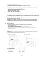
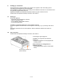
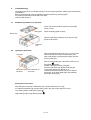
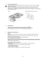
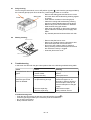
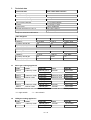
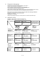
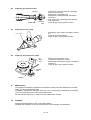
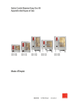
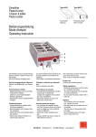
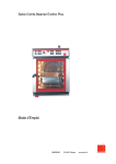
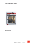
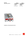
Smartline
Gas cooking appliance
Table-top unit AKG2
Built-in unit BKG2
Installation and Operating Instructions
SALVIS AG Nordstrasse 15 CH-4665 Oftringen
www.salvis.ch
2 / 13
Dear customer,
Before you operate the gas cooking appliance, please read the Installation and Operating Instructions
carefully.
These instructions contain important information about proper installation and operation.
Any documents supplied with the appliance should always be kept readily available and should be
handed on with the appliance.
Application
For all cooking applications with cooking or frying utensils.
Notes
The appliance is manufactured according to the requirements of the
relevant European standard (EN 203-1).
The appliance is factory-set to high-calorific natural gas (type H).
Entering the name
plate information
Before setting up the appliance please enter the name plate
information below. Please provide this information when requesting a
service or spare parts for the appliance. It will help us to respond to
your query more quickly.
Type:
Year of manufacture:
Appliance no.:
3 / 13
CONTENTS
1.
Hints on operational safety.................................................................................................. 5
1.1
Daily operation ......................................................................................................... 5
1.2
Risk of injury ............................................................................................................ 5
1.3
Fire hazard............................................................................................................... 5
1.4
Risk of damage ........................................................................................................ 5
1.5
Connection, changeover, maintenance ................................................................... 5
1.6
Swiss regulations..................................................................................................... 6
2.
Setting up, connection......................................................................................................... 7
2.1
Setting up................................................................................................................. 7
2.2
Gas connection ........................................................................................................ 7
3.
Commissioning.................................................................................................................... 8
3.1
Establishing readiness for operation ....................................................................... 8
3.2
Igniting the pilot flame.............................................................................................. 8
3.3
Notes regarding operation ....................................................................................... 9
4.
Switching off ........................................................................................................................ 9
5.
Cleaning and maintenance ................................................................................................. 9
5.1
Daily cleaning......................................................................................................... 10
5.2
Weekly cleaning..................................................................................................... 10
6.
Troubleshooting................................................................................................................. 10
7.
Technical data ................................................................................................................... 11
7.1
Salvis gas cooking appliances............................................................................... 11
7.2
OEM gas cooking appliances ................................................................................ 11
8.
Changeover to other gas type........................................................................................... 12
8.1
Nozzle table / overview.......................................................................................... 12
8.2
Replacing the external nozzle................................................................................ 13
8.3
Replacing the low nozzle ....................................................................................... 13
8.4
Replacing the pilot burner nozzle .......................................................................... 13
9.
Maintenance...................................................................................................................... 13
10.
Disposal............................................................................................................................. 13
Aarburg, 20 April 2007
Article no. BI 371'932 E
4 / 13
1.
Hints on operational safety
1.1
Daily operation
The appliance must only be operated
- by trained staff,
- under supervision,
- for the purpose specified in the operating instructions.
- Outdoors the appliance may only be operated under a cover and with adequate wind
protection! Keep the appliance dry!
- Do not use the appliance for storage purposes!
- Do not use cookware that covers the whole surface!
- Only use cookware suitable for gas cookers.
- The appliance must not be used for deep-frying!
- If a malfunction cannot be rectified by following the instructions in the troubleshooting section
(section 5), close the gas control knob (position ), close the gas tap, and notify customer
service.
1.2
Risk of injury
Risk of burns!
The upper part of housing and the sliding grate become hot during operation!
Existing combustion air supply and exhaust gas installations must not be modified, e.g.:
- Reducing the installation space;
- Subsequent sealing of windows and doors;
- Closing or removing the combustion air supply openings.
1.3
Fire hazard
Do no place inflammable objects on the appliance!
Fire extinguishers approved for cooking oil and fat fires must be made available.
1.4
Risk of damage
Do no allow liquids to enter the burner or pilot burner!
Risk of blocking the nozzles!
Do not place any empty saucepans or frying pans on the hob when the appliance is switched on
in order to prevent damaging your cookware or the glass ceramic hob.
Do not place hot cookware on stainless steel tabletops or work surfaces in order to prevent
permanent deformation.
Do not hose down or clean the appliance with a water hose, high-pressure cleaner, steam highpressure cleaner or steam cleaner!
After prolonged periods of non-use the functionality of the appliance should be checked as part of
a service!
1.5
Connection, changeover, maintenance
The appliance must be connected by an approved gas installer!
In commercial kitchens work on gas equipment such as:
- Changeover to other gas type
- Inspection, maintenance
- Repairs
- Commissioning
may only be carried out by:
- the gas supply company;
- a competent representative of the manufacturer;
- an installation contractor; or
a distribution agency authorised by a liquid gas supplier.
5 / 13
Before connecting the appliance:
- notify the relevant gas supply company;
- check that the gas type set at the appliance matches the gas on site;
During inspection, connection, changeover or maintenance of the gas appliance check the:
- exhaust gas route from the installation space;
- fresh air supply to the combustion units;
- leakproofness of the gas-carrying parts (leak spray);
- fire safety and combustion quality;
- ignition, safety and control equipment.
The technical regulations for gas installation DVGW-TRGI Gas must be followed: G 600
(DVGW-TRGI 1986, G 628, G 634, G 660, and technical regulations for liquid gas TRF).
The installations must be carried out according to the installation instructions of manufacturer and
the generally accepted state of the art.
Protect the gas supply line from overheating!
Only original and suitable burner components must be used. Installation of other components and
so-called gas economisers is prohibited.
If the appliance is installed in conjunction with electrical appliances, the equipment must be
included in an equipotential bonding system. The effectiveness must be verified according to
VDE 0 190.
1.6
Swiss regulations
The following regulations must be followed during setting up and installation:
- SVGW gas regulations G1
- FCOS guideline no. 1942: liquid gas, part 2
(FCOS: Federal Coordination Commission for Occupational Safety)
- regulations of the "Vereinigung Kantonaler Feuerversicherungen - VKF" (association of
cantonal fire insurers)
Safety clearances specified by t manufacturer between inflammable material (fire protection
distance):
The built-in unit may only be installed in a CNS cover.
Table-top unit AKG2
Key for safety distance:
- to rear panel
- to side panel
- to top surface
- to cooker hood
Built-in unit BKG2
SA/R
SA/S
SA/O
SA/A
100 mm
200 mm
650 mm
650 mm
6 / 13
2.
Setting up, connection
During transport by hand: Be aware of the weight of the appliance and wear safety gloves!
The relevant local regulations must be followed.
The installations must be carried out according to the installation instructions of manufacturer and
the generally accepted state of the art.
Appliance installation and induction should be carried out by the customer service.
Please follow the operational safety instructions, see section 1.
2.1
Setting up
Set up the appliance:
- horizontally and protected from vibration,
- under an extraction hood,
- not on heated or inflammable surfaces;
- not at inflammable walls.
Installation of individual appliances on narrow tables or frames:
Secure the appliance and the table or frame against overturning, e.g. by screwing to the wall or
floor.
Remove the protective film from the appliance. Remove adhesive residues with solvent or
benzine.
2.2
Gas connection
Please follow the operational safety instructions, see section 1.
Connecting the gas supply line:
Installation in conjunction with electrical
appliances:
- Connect the appliance to the equipotential
bonding system.
After connection or changeover to a
different gas type:
- Check all gas-carrying parts for leaks (leak
spray).
Gas connection thread T1/2“
(external thread)
7 / 13
3.
Commissioning
The appliance must be connected properly to ensure proper operation. Setting up and connection
see section 2.
Before commissioning clean the appliance with a fat-dissolving cleaning agent.
Dry cleaned parts and surfaces with a soft cloth.
Cleaning see section 5.
3.1
Establishing readiness for operation
Check the correct position of the burner and pilot
burner covers.
Sliding grate
Place the sliding grate correctly.
Burner cover
Open the gas tap provided by the customer (main
gas shut-off device).
Pilot burner
cover
3.2
Igniting the pilot flame
Gas lighter
After prolonged periods of non-use, e.g. if the (main
shut-off device was closed, the pilot flame may
take a little longer to ignite (the gas supply line first
has to fill with gas).
Push in and hold the gas control knob, and turn it to
Gas control knob for Gas control knob for
front burner
rear burner
the ignition
symbol.
Ignite the pilot flame with a gas lighter.
Once the pilot flame has ignited, keep the gas
control knob pressed for approx. 5-10,
to allow the thermocouple to heat up, so that the
gas supply is not interrupted again automatically
(automatic safety pilot).
Setting the burner flame
After the ignition procedure release the gas control knob and set it to high.
For switching between high and low flame push in the gas control and turn it to low.
Low heating output, small flame symbol
High heating output, large flame symbol
8 / 13
3.3
Notes regarding operation
Any spillage or boiled over food residue should be removed from the gas cooker immediately!
Caution - hot surfaces!
The gas cooker is equipped with a thermoelectric safety pilot. If the pilot flame goes out the
safety pilot automatically interrupts the gas supply, thereby preventing gas from escaping.
The gas cooker is equipped with different burner output levels. This is apparent from the different
sizes of the burner covers.
Hobs
4.
Operating panel for built-in module
Switching off
Push the gas control knob and turn to the Off position (symbol ).
Close the gas tap provided by the customer gas tap (main shut-off device).
Clean the appliance, see section 5 below, "Cleaning and maintenance".
5.
Cleaning and maintenance
Notes
Avoid corrosive cleaning agents coming into contact with the operating panel and the rotary
switches!
Do not hose down or clean the unit with a water hose, high-pressure cleaner, steam highpressure cleaner or steam cleaner!
Follow the instructions of the cleaning agent manufacturers!
Do not use abrasive cleaning agents!
Stainless steel must not come into prolonged contact with concentrated acids, vinegar essence,
saline solution, mustard, spice mixtures, in order to avoid damage to the protective layer. Rinse
stainless steel surfaces after use.
Cleaning agents and care products
Suitable cleaning agents and care products are available from customer service.
These include:
- Fat-dissolving cleaning agents or special stainless steel cleaners;
- Stainless steel grill cleaner;
- Stainless steel care products.
Further information is available from your customer service agent.
9 / 13
5.1
Daily cleaning
Push in the gas control knob, turn to Off position (symbol ) and close the gas tap provided by
the customer gas tap (main shut-off device). Leave the gas cooker to cool down.
Sliding grate
Burner cover
5.2
- Remove the sliding grate and the burner covers
and clean them with fat-dissolving cleaning agents
in a basin.
- Soak stubborn residues in the rinsing liquid.
- Clean the housing with fat-dissolving cleaning
agents or special stainless steel care products.
- Remove any burnt food residue from stainless
steel surfaces using grill cleaner.
- After using grill cleaner or other strong cleaning
agents, wash the cleaned parts thoroughly with
water.
- Dry cleaned parts and surfaces with a soft cloth.
Weekly cleaning
Pilot burner cover
- Remove the pilot burner cover.
- Remove any residues from the pilot burner and
the thermocouple with a fine wire brush.
- Do not use wet or damp cloths for cleaning!
During cleaning ensure that the pilot burner and
the nozzle are not dirty / clogged!
- Insert the pilot burner cover.
Pilot burner
Thermocouple
6.
Troubleshooting
In the event of a fault with the gas cooker please refer to the following troubleshooting table:
Fault
Cause
Remedy
The pilot flame does not
ignite.
Gas tap/main shut-off
device closed.
Open gas tap/main shut-off
device.
Pilot burner dirty
Clean pilot burner.
The gas control knob was
not pressed long enough.
Keep the gas control knob
pressed for approx. 5-10
seconds, in order to allow the
thermocouple to heat up and
prevent interruption of the gas
supply.
Thermocouple dirty
Clean thermocouple.
Thermocouple faulty.
Notify customer service.
The pilot flame goes out
when the gas control
knob is released.
If troubleshooting fails:
- Push the gas control knob in and turn to the Off position (symbol ),
- Close the gas tap provided by the customer (main shut-off device,
- Do not open the housing;
- Notify customer service.
10 / 13
7.
Technical data
Technical data
Gas cooker with 2 burners
Gas appliance type
A1
Rated heat load (total)
8.5 kW
Connected load, liquid gas
0.66 kg/h
Connected load, natural gas
0.9 m3/h
Gas connection diameter
T 1/2" (external thread)
Cookers
1 x 3.5 kW; 1 x 5 kW
Control range
Large / small flame
External dimensions (W x D x H)
400 x 600 x 295 mm
Weight
approx. 19 kg
Subject to technical modifications!
Gas categories
Country
CH
CH
DE
Category
II 2H 3B/P
II 2H 3+
II 2ELL 30/P
P (mbar) natural gas
20
20
20
P (mbar) liquid gas
50
28-30/37
50
Country
GB
BE
NL
Category
II 2H 3+
II 2E+ 3+
II 2L 3B/P
P (mbar) natural gas
20
20/25
25
P (mbar) liquid gas
28-30/37
28-30/37
30
Gas categories
7.1
Salvis gas cooking appliances
Type
Name
Gas type
mbar
Item No.
AKG 2
Table-top model
Natural gas H*
20 mbar
BI 371'922
BKG 2
Built-in model
Natural gas H
20 mbar
BI 371'923
AKG 2
Table-top model
Liquid gas
28-30/37 mbar
BI 371'924
BKG 2
Built-in model
Liquid gas
28-30/37 mbar
BI 371'925
AKG 2
Table-top model
Liquid gas
50 mbar
BI 371'926
BKG 2
Built-in model
Liquid gas
50 mbar
BI 371'927
AKG 2
Table-top model
Natural gas L**
25 mbar
BI 371'928
BKG 2
Built-in model
Natural gas L
25 mbar
BI 371'929
Product line extension with consideration of SVGW and DVGW test certificates possible.
* H = high-calorific
7.2
** L = low-calorofic
OEM gas cooking appliances
Type
Name
Gas type
mbar
Item No.
AKG 2
Table-top model
Natural gas H
20 mbar
CE 371'922
BKG 2
Built-in model
Natural gas H
20 mbar
CE 371'926
11 / 13
8.
Changeover to other gas type
Please follow the operational safety instructions, see section 1.
The gas cooker factory-set to natural gas H.
Only use original nozzles for changeover to other gas types.
After changeover to another gas type and after maintenance work
check all gas-carrying parts for leaks (leak spray).
Attach a sticker to the gas cooker indicating the gas type and gas admission pressure (mbar).
Please refer to the nozzle table/overview for changeover data, see section 8.1.
Warning! Do not set up and commission the gas cooker if the actual gas admission
pressure is outside the range specified below:
Natural gas 18 - 25 mbar
Liquid gas 42.5 - 57.5 mbar
Notify your gas supply company If the actual pressure is outside the specified range!
8.1
Nozzle table / overview
C burner: rated heat load 3.5 kW, low heat load 1 kW
D burner: rated heat load 5.0 kW, low heat load 1.3 kW
Nozzle type
External nozzle
Low nozzle
Pilot burner nozzle
See section 8.2
Setting up, see section
8.3
Replacing the pilot
burner nozzle, section
8.4
Natural gas H
admission
pressure 20 mbar
Burner
C = dia. 1.35 mm
Burner
C = dia. 0.75 mm
D = dia. 0.85 mm
screw in the low nozzle
fully
Burner
C = dia. 0.32 mm
D = dia. 0.32 mm
Natural gas LL
admission
pressure 20 mbar
Burner
C = dia. 1.50 mm
D = dia. 1.80 mm
Burner
C = dia. 0.75 mm
D = dia. 0.85 mm
screw in the low nozzle
fully
Burner
C = dia. 0.32 mm
D = dia. 0.32 mm
Liquid gas B/P
admission
pressure 50 mbar
Burner
C = dia. 0.80 mm
D = dia. 0.95 mm
Burner
C = dia. 0.40 mm
D = dia. 0.45 mm
screw in the low nozzle
fully
Burner
C = dia. 0.18 mm
D = dia. 0.18 mm
Liquid gas
3+
admission
pressure
28-30/37 mbar
Burner
C = 0.95 mm
D = 1.10 mm
Burner
C = 0.50 mm
D = 0.55 mm
screw in the low nozzle
fully
Burner
C = 0.18 mm
D = 0.18 mm
Natural gas L
admission
pressure
25 mbar
Burner
C = 1.35 mm
D = 1.65 mm
Burner
C = 0.75 mm
D = 0.85 mm
Burner
C = 0.32 mm
D = 0.32 mm
Gas type
D = dia. 1.65 mm
12 / 13
8.2
Replacing the external nozzle
Set screw
External nozzle
8.3
Connecting
piece
Replacing the low nozzle
Replacing the low nozzle, see table in section
8.1.
Screw in the low nozzle fully.
Check all gas-carrying parts for leaks.
Low nozzle
8.4
Unscrew the set screw until the connecting
piece can be removed.
Remove the connecting piece.
Replacing the external nozzle, see table in
section 8.1.
Fully push in the connecting piece and lock
with a set screw.
Check all gas-carrying parts for leaks.
Replacing the pilot burner nozzle
Remove the pilot burner cover.
Unscrew the pilot burner nozzle.
Replacing the pilot burner nozzle, see table in
section 8.1.
Check all gas-carrying parts for leaks
Pilot
burner
cover
Pilot burner
nozzle
Pilot burner
9.
Maintenance
This appliance should be inspected and serviced at regularly intervals. Maintenance includes
safety, functional and leakage tests.
Installation, maintenance and repair work may only be carried out by qualified gas technicians.
Only use original accessories and original spare parts!
We recommend setting up a customer service maintenance contract.
10.
Disposal
Decommissioned appliances are not worthless waste!
Valuable raw materials can be recovered through environmentally sound disposal.
13 / 13
SALVIS AG
Nordstrasse 15
CH-4665 Oftringen
Phone +41 62 788 1818
Fax +41 62 788 1895
www.salvis.ch
[email protected]