1
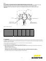
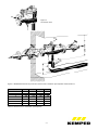
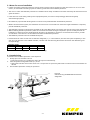
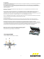
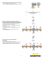
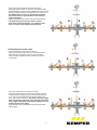
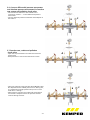
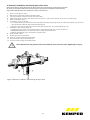
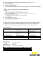
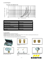
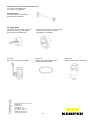
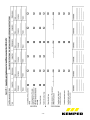
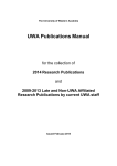
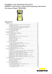
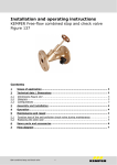
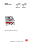
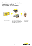
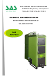
Installation and operating instructions KEMPER Backflow Preventer BA Figure 361 1. Prerequisites for installation Install the backflow preventer in frost-free areas only! Comply with standards: DIN EN 1717, DIN 1988 DIN EN 12056, DIN 1986-100 Provide a drain line! Comply with the direction of flow! Application area According to DIN EN 1717, in order to maintain flawless functioning of the BA backflow preventer, a flanged dirt trap must be installed in the direction of flow before the BA backflow preventer. Type BA backflow preventers that accord with DIN EN 12729 are used to secure drinking water plants against back pressures and siphon back flow. Fluids up to and including Fluid Category 4 as per DIN EN 1717/1988-100 are secured. They can be used for residential buildings, industrial and commercial purposes with consideration of their specifications. Normally (normal functioning with pressure fluctuations), the vent hole of the middle pressure chamber only allows a few drops through. During malfunctions, the vent hole can allow the full volume flow of the service pipe through. For that reason, dimension the wastewater connection to be sufficiently large according to DIN EN 12056 and DIN 1986-100. Assume the volume flow that could arise through the service pipe on the backflow preventer BA (pay attention to the nominal flow rate!). The backflow preventer BA can secure the following hazard potential in accordance with the Fluid Category: Category 4 (applies to backflow preventer BA) Fluids that present a health hazard to humans due to the presence of one or more toxic or highly toxic substances or one or more radioactive, mutagenic or carcinogenic substances. The higher the classification, the greater the risk potential. For each category, DIN EN 1717 stipulates specific protection valves. The Backflow Preventer BA, Figure 361 is approved without restriction for use up to and including Category 4. A continual bacterial risk (Fluid Category 5) in extant piping systems must not exist. 2. Operating principle The KEMPER BA Backflow Preventer is subdivided into 3 zones. In Zone 1, the pressure is higher than in Zone 2 and there again higher than in Zone 3. A drain valve is connected to Zone 2, which opens latest when the pressure difference between Zones 1 and 2 has decreased to less than 0.14 bar. The water from Zone 2 flows outdoors. That precludes the risk of backpressure or siphon back flow in the supply network. The pipeline is interrupted and the drinking water network is protected. Intermittent dripping from the BA Backflow Preventer at the drain valve is not necessarily a malfunction. Under such circumstances, the BA Backflow Preventer separates as intended! -1- Note: Do not connect any fast-closing valves or stopping equipment before or after the valve. Fast closing, e.g. of solenoid valves or ball valves on devices and machines can lead to serious malfunctions in the backflow preventer BA. For that reason, always use slowly closing valves or drives that close slowly. If the inlet-side static system pressure is high, it is recommended to install a pressure reducing valve in the supply line. Zone 2 Zone 1 Zone 3 Supply-side antipollution check-valve Discharge-side antipollution check-valve Drain valve Figure 1: Sectional view Dimension Nominal width DN 65 Installation height (H) mm 245 Installation height (h) mm 270 Installation depth (D) mm 60 Length (L) mm 559 Nominal flow at delta p=1 bar m³/h 45 Weight kg 31.3 Table 1: Dimensions: Backflow Preventer BA Figure 361 80 245 270 60 559 54 32.6 100 245 300 60 559 85 34 150 285 300 60 695 191 52.6 3. Installation The BA Backflow Preventer must be installed level. Provide cut-off valves in front of and behind the backflow preventer. In addition, a dirt trap must be connected upstream which prevents the backflow preventer from damage and functional impairments due to coarse dirt. Install the backflow preventer free of tension and without flexural moment as follows: 1. Thoroughly rinse connecting pipe 2. Check connections on backflow preventer for cleanliness (Figure 2) 3. Install backflow preventer as in Figure 3. While doing so, comply with the following points and those in Chapter 3.1: Flow in direction of arrow Maintain installation clearances Make sure there is good accessibility Make drain lines without any tight bends and keep them short. Connection dimension acc Table 2 Install the drain line so that the drain connection and the drain valve can be removed for inspection. A material-steadying zone of 5 x DN after the BA is recommended -2- Figure 2: Connection area Figure 3: BA Backflow Preventer protection device with installation prerequisites and dimensions. Connection sizes 65 80 100 A 650 650 650 B 600 600 600 C 160 160 160 D 150 150 150 E 345 345 345 F 895 895 895 G 75 75 75 (Dimensions in mm) Table 2: Dimensions for installation prerequisites 150 650 600 200 150 375 935 75 -3- 3.1 Notes for secure installation If there are supply pressure fluctuations, without water removal a short triggering of the drain valve can occur. For that reason, we recommend installing a pressure reducing valve before the backflow preventer. The room in which the backflow preventer is installed must be freely accessible at all times and always be frost free. Ensure good ventilation. If the drain line is also being used by other equipment/plants, it must be correspondingly dimensioned (pump stations/sewage system) No additional, unprotected drinking water connections are permitted after the backflow preventer. Within the downstream system, the individual connections are not secured from each other against backflow. If required, provide individual protection. The backflow preventer must be easily accessible at all times. Manometer connections and controls must not be obstructed. While installing backflow preventers, make sure the water that leaks during the separation process is safely drained off. Installation in shafts and rooms endangered by flooding is prohibited. For inspection and maintenance reasons, provide cut-off valves in the direction of flow before and after the backflow preventer. The backflow preventer must be installed flood proof. Provide the drain valve control with an effective safeguard, i.e., in case of failure, the vent hole opens completely. In this case, for 1 bar pressure in the middle chamber, calculate with the following dimensions. Dimension the dewatering line correspondingly. Hydraulic values DN 65 m³/h 35 80 35 100 35 150 35 Table 3: Drain lines (sewage system connection dimensioning) 4. Commissioning Commission the backflow preventer in this sequence: 1. Slowly open cut-off valves 1 and 2. During this process, it is possible the drain valve opens intermittently. 2. Vent the system through ball valves 3, 4, and 5. Open each ball valve until water comes out. It is important to open every ball valve to make sure that all chambers are vented. 3. The backflow preventer is ready for operation. Figure 4: Commissioning the BA Backflow Preventer safeguards -4- 5. Inspection In compliance with standards on drinking water protection and hygiene regulations, the user/operating organisation is given the following specifications: As per DIN EN 1717, Point 4.6, perform regularly scheduled maintenance on the safeguards. As per DIN EN 806-5 1 x annual maintenance is applicable Europe-wide. Check their proper functioning in regularly scheduled intervals in compliance with the national or regional stipulations. For DE, in accordance with DVGW W 570-1 (April 2007) under 4.7 it is stipulated that the maintenance must be performed 1 x annually. For CH, perform the maintenance/inspection as per SVGW W3 Supplement 1 (2000), W/TPW 126 (April 1994) and W/TPW 135 (April 1994). In W/TPW 135, in Point 3 Maintenance, the maintenance/inspection is stipulated as periodical, but at least every 2 years. W/TPW 126 requires the backflow preventer BA to be checked for the first time after the first year of operation. In addition, Offprint no. 1377 of SVGW 8/96 is pointed out. For NL, in VEWIN Waterwerkblad WB 1.4 G (November 2005 under Point 4 it is stipulated that backflow preventers BA need to be checked for proper operation and maintained 1x annually. The following applies: The functional and maintenance measures cover the function test, visual inspection of the interior parts and the cleaning or replacement of the functioning parts as stated under Points 3 and 4 in the operating instructions. This inspection should also include the related valves. Only authorised specialists are allowed to perform maintenance. Document the inspection on the attached control plate with date and signature. In addition, Appendix 1 on inspection and maintenance is recommended. Put the Backflow preventer BA cartridge through a visual inspection in the installed state during every maintenance to the extent this is possible through the housing opening. The manufacturer recommends replacing the cartridge every 10 years. Comply with local regulations. Measuring instrument for differential pressure measurement: Suitable differential pressure manometer; The KEMPER differential pressure measurement case, Figure 360 99, is recommended. 5.1 Connect test adapter - Screw on adapter G1/2-G1/4 - Screw on adapter G1/4 with plug-on coupling A B C -5- 5.2 Preparing the differential pressure manometer - Connect the test hose with the adapter *+* and *-* of the differential pressure manometer to each side. 5.3 Connect differential pressure manometer for function test inlet anti-pollution check-valve and drain valve - For each test hose, plug on and latch a quick coupler to the adapter (bleeder valves must be closed on the hoses.) - Connect the test hose of Test valve A to the connection marked ``+``` on the differential pressure manometer. - Connect the test hose of Test valve B to the connection marked ``-``` on the differential pressure manometer. - A = Supply pressure zone, B = Middle pressure zone, C = Back pressure zone + ‐ A B C + ‐ 5.4 Function test, inlet anti-pollution check-valve - Connect measuring instrument as per 4.3 - Open Test valves A and B and vent the measurement lines through the bleeder valves on the test hoses. Then close the bleeder valves and leave Test valve A and B open. -6- A B C - Close the stop valve before and after the valve. - Using the bleeder valve on the test hose (Test valve B), slowly bleed the pressure of the middle pressure zone and watch the differential pressure display at the same time. The differential pressure rises until the anti-pollution check-valve starts to open. The drain valve must not trigger during this. - Close the bleeder valve on the test hose (Test hose B). The differential pressure must remain constant. Note: During the measurement, it is mandatory that there is no flow in the backflow preventer BA! + ‐ B A C + ‐ 5.5 Function test, drain valve - Connect measuring instrument as per 4.3 - Open Test valves A and B and vent the measurement lines through the bleeder valves on the test hoses. Then close the bleeder valves and leave Test valve A and B open. A B C + ‐ - Close stop valve before and after the valve - Using the bleeder valve on the test hose (Test valve A), slowly bleed the supply pressure of the supply pressure zone and watch the differential pressure display and drain valve at the same time. The drain valve must trigger before the display reaches the value 140 mbar (when the valve triggers, the differential pressure initially rises only slightly and then falls again)! - Close bleeder valve. The bleeder valve must be closed tightly again. -7- A B C 5.6 Connect differential pressure manometer and absolute pressure manometer for function test output anti-pollution check-valve - Connect the test hose from Test valve B to the connection marked ``-`` on the differential pressure manometer. - Connect absolute pressure manometer with adapter to Test valve C. + ‐ A B C + ‐ 5.7 Function test, outlet anti-pollution check-valve A - Open the stop valve before and after the valve and fill the valve. - Read pressure on scale and write down the value. C B + ‐ - Close stop valves and use Test valve B and Bleeder valve B to depressurise the middle pressure zone. During this, it is possible that a slight pressure drop occurs on the scale due to "setting". - Wait at least 2 minutes. The outlet-side anti-pollution check-valve is leakproof when the pressure remains constant during this time. -8- A B C 6. Removal, installation and cleaning the drain valve Both anti-pollution check-valves and the drain valve can be removed for maintenance purposes. All work can be performed without removing the housing from the pipeline (inline service). Only authorised specialists are allowed to perform maintenance. 1. 2. 3. 4. 5. 6. Close cut-off valves 1 and 2. Reduce the pressure by opening the ball valves. Unscrew pressure control line 14 on the drain valve. After loosening the screws, pull down drain connection 7 and unscrew with the help of an oil filter strap. Take off the drain valve. If necessary, clean or replace. If no dirt particles are visible but a fault was observed while inspecting the drain valve (see Chapter 5.2), the drain valve should be replaced (see accessories/spare parts). Clean the area around the valve seat and the opening slot (e.g., by carefully blowing out) 7. Assemble in the reverse sequence. Grease the O-rings well with Unisilikon 250 or a grease that does not contain mineral oil. ATTENTION! Otherwise it is possible that the O-rings will be destroyed. Replace damaged O-rings, see Chapter 13, Spare parts 8. Close the ball valves. 9. Slowly open the cut-off valves. 10. Vent the system through the ball valves. 11. Check the drain valve, see Chapter 5.2. 12. Connect the dust plugs to the ball valves. Never dismantle the anti-pollution check valve and drain valve from each other. High danger of injury! Figure 7: Removal, installation and cleaning the drain valve -9- 6.1 Removal, installation and inspecting the anti-pollution check valve (refer to Figure 4) 1. 2. 3. 4. Close cut-off valves 1 and 2. Reduce pressure by opening ball valves 3, 4, and 5. Take off cover. Remove the anti-pollution check-valve. For DN 65-150, first unscrew the discharge anti-pollution check valve and then the supply anti-pollution check valve. You can obtain an assembly tool as an accessory. Danger of injury! The anti-pollution check-valve is spring preloaded. 5. Check for leakproofness by filling water from the rear. Leaky anti-pollution check-valves must be replaced. Repair is not possible. 6. Assemble in the reverse sequence. For DN 65-150: - grease O-ring and thread well on the anti-pollution check valve with Unisilikon 250. Do not damage the O-ring when installing. The tightening torque for the anti-pollution check-valve is 100-120 Nm. 7. Close the ball valves. 8. Open the cut-off valves. 9. Vent the system through the ball valves. 10. Check the backflow preventer, see Chapters 5.1 to 5.3. 11. Connect the dust plugs to the ball valves. 7. Important information instructions for your safety Use the device solely in a technically flawless condition and as intended for use, safety and hazard aware while complying with the installation and operating instructions. Have all malfunctions that could impair safety repaired immediately. The BA Backflow Preventer, Figure 361, is intended solely for the application areas named in these installation and operating instructions. Any different use or use beyond and above that is considered non-intended usage. 8. Troubleshooting Errors Other Possible causes Strong pressure fluctuations in the water network. Fluctuating admission pressure Remedy Install a water surge (hammer) damper behind the backflow preventer Install a pressure reducer before the backflow preventer Remove and clean anti-pollution check valve Supply-side anti-pollution check valve or drain valve is soiled Leaky supply anti-pollution check valve Remove the anti-pollution check valve Deposits on the valve seat Remove the drain valve Damaged O-rings Remove drain valve and replace O-ring Leaky drain valve Remove the drain valve Clogged pressure control line Remove and clean the pressure control line Drain valve does not close Drain valve does not open Table 4: Troubleshooting 9. Technical data Total pressure drop: Flow media: Operating pressure: Minimum supply pressure: Ball valve connection: max. 1.0 bar at nominal flow Water at 60 °C max. 10 bar 1.5 bar G ½ with connection size DN 65-150 Connection sizes Weight ca. in kg DN 65 32 DN 80 32.5 DN 100 33 DN 150 57 Table 5: Technical data Total length in mm 559 559 559 695 - 10 - Nominal flow rate in m³/h 45 54 85 191 10. Flow diagram Pressure drop in valve Δp (bar) Connection sizes DN 65 to 150 Flowrate V (m h) 3 11. Materials Housing Anti-pollution check-valve Other interior parts Compression spring Sealing disc Drain valve housing Drain valve, other interior parts Drain valve, compressed spring Drain valve, membrane Drain valve, sealing disc Drain valve Table 6: Materials Stainless steel Stainless steel Stainless steel Stainless steel EPDM Stainless steel POM Stainless steel EPDM EPDM Stainless steel 12. Accessories KEMPER differential pressure measuring case Differential pressure manometer in a representative aluminium case, ideal for inspecting and maintaining all KEMPER BA Backflow Preventers, Figures 360 and 361 Content of the Differential Pressure Measurement Kit, Figure 360 99 Differential pressure manometer with scale range to 1 bar 2 G1/4 adapters with plug coupling 2 G1/2 and G1/4 adapters 2 test hoses, preassembled with plug-and-socket connections and bleed valves 1 absolute pressure manometer with scale range to 10 bar - 11 - Replacement tools for anti-pollution check-valve For flange version DN 65-100 For flange version DN 150 Assembly wrench DN 65-DN 100 Figure 361 99 009 DN 150 Figure 361 99 010 13. Spare parts Anti-pollution check valve, supply side DN 65 – DN 100 Figure 361 98 002, DN 150 Figure 361 98 006 010 K410036100002-00 01/14 Technical subject to change. Ball valve DN 65 - DN 150 Figure 361 99 004 Gebr. Kemper GmbH + Co. KG Metallwerke Harkortstr. 5 D-57462 Olpe Tel. 0 27 61 - 8 91 - 0 Fax 0 27 61 - 8 91 -1 75 [email protected] www.kemper-olpe.de T Anti-pollution check valve, discharge side DN 65 - DN 100 Figure 361 98 003, DN 150 Figure 361 98 007 Gasket set DN 65 – DN 100 Figure 361 99 005 DN 150 Figure 361 99 008 T - 12 - Bleed valve DN 65 – DN 150 Figure 361 98 001 - 13 -