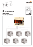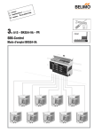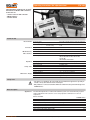
1
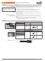
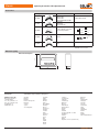
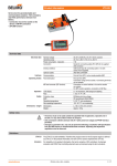
Operating instructions VAV adjustment tool ZTH-VAV VAV adjustment and diagnostic tool with PP interface for Belimo VAV controllers. Connection via • Service socket on VAV controller • MP/PP interface • Control cabinet Technical data Electrical data Nominal voltage Power supply range of VAV controller Power consumption In operation For wire sizing From VAV controller, AC 24 V, 50/60 Hz / DC 24 V AC 19.2 ... 28.8 V / DC 21.6 ... 28.8 V 1W 2 VA Plug socket for Belimo PP interface Connecting cable RJ12 socket See page 6 MP/PP interface Communication PP, no MP operation VAV controllers VAV-Universal VAV-Compact VRD2, VRD3, VRP-M (VAV & STP) NMV-D2, LMV-D2M, NMV-D2M LMV-D2-MP, NMV-D2-MP, SMV-D2-MP, LHV-D2-MP LMV-D2LON, NMV-D2LON LC display Buttons Quick start guide 2 x 16 characters with backlighting ▼ / ▲ / – / + / OK Included, en/de Protection class EMC Operating temperature Storage conditions III Safety extra-low voltage CE according to 89/336/EEC 0 ... 50°C, non-condensing –20 ... 50°C, non-condensing Dimensions Weight See page 8 Approx. 260 g Connection Operation Safety / tests Dimensions / weight Safety notes ! • The device is not allowed to be used outside the specified field of application, especially in aircraft or in any other airborne means of transport. • Only suitable for connection to Belimo VAV devices with 24 V safety extra-low voltage and a PP/MP interface. Brief description Applications The ZTH-VAV adjustment tool enables VAV and CAV systems to be tested efficiently. Systems equipped with Belimo VAV controllers can be easily adjusted to individual room and user requirements. Can be used with: VAV-Universal VRD2, VRD2-L VAV-Universal VRD3 1) VAV-Universal VRP-M [VAV and STP (pressure application)] VAV-Compact NMV-D2 VAV-Compact LMV-D2M, NMV-D2M VAV-Compact LMV-D2-MP, NMV-D2-MP, SMV-D2-MP, LHV-D2-MP VAV-Compact LMV-D2LON, NMV-D2LON 1)Requires www.belimo.com available since: 1992–2007 from 2008 from 2005 1992–2000 2000–2006 2006 2006 ZTH-VAV Firmware V1.02 or higher T4-ZTH-VAV • en • v1.2 • 03.2009 • Subject to changes /8 ZTH-VAV Operating instructions VAV adjustment tool Brief description (Continued) Connection and supply Stand-alone operation: The tool can be connected and supplied using the service socket on the VAV controller or the connecting terminals. Bus operation: If the ZTH-VAV is connected to the local service socket, it can be used to test the following devices without interrupting the bus: VAV-Compact L/N/SMV-D2-MP and L/NMV-D2LON. The MP-Bus must be disconnected in order to test the VRP-M and L/NMV-D2M when the service socket is used. Limitation The tool cannot be directly connected in an MP network or via an MP-Bus master. ZTH-VAV ZTH-VAV ▲ ▼ – + OK ▲ ▼ – + OK MP6 MP6 MP7 MP7 MP1 MP1 MP8 MP4 MP5 MP2 MP-Master MP8 MP4 MP3 MP-Master MP5 MP2 MP3 Operating instructions These operating instructions describe handling of the ZTH-VAV adjustment tool. For a detailed description of VAV controllers, please refer to the separate product documentation, which can be downloaded from www.belimo.eu ¦ Documentation ¦ Room & System Solutions. A quick start guide in English and German is included with the ZTH-VAV as a sticker that can be affixed to the rear of the device. Compatibility The ZTH-VAV adjustment tool supersedes the old ZEV adjustment tool (1992–2007). All standard Belimo VAV controllers with integrated PP communication that are sold in EU countries (from 1992) can be adjusted using the ZTH-VAV. Belimo Automation AG reserves the right to make changes or improvements at any time without prior notice. The latest version of these operating instructions is published on our website: www. belimo.eu. Connection See page 6. Operation Buttons, display RJ12 connection: PP / 24 V See page 6 Device rear, quick start guide /8 LC display, 2 x 16 characters with backlighting ▼▲ Scroll up / down, cancel – + Change value OK Confirm A quick start guide in English and German is included with the ZTH-VAV as a sticker that can be affixed to the rear of the device. Contents: – Connection – Overview of types – Access to Configuration menu – Operating menu with navigation tree T4-ZTH-VAV • en • v1.2 • 03.2009 • Subject to changes www.belimo.com ZTH-VAV Operating instructions VAV adjustment tool Operation (Continued) Configuration menu You can set the language and the volumetric flow units in the Configuration menu. The settings are stored. Start Configuration menu Options Action: Keep the (OK) button pressed while you connect the tool to the VAV controller. Reaction: «Configuration menu» appears on the display Continue with: (▼ ▲) buttons Exit: Menu option «leave config-menu» or disconnect cable Text German * / English Units m3/h *, l/s, cfm Supply AC 24 V AV 24 V voltage indication, refer to page 7 for an explanation MP tester MP-Bus level tester MP-Bus diagnostic tool for system integrators The MP tester is not included in this documentation. Expert Mode 0 */ 1 Activates mode switching, Restores original min / max values Advanced Mode 0 */ 1 Activates the direction-of-rotation setting * Default Menu Actual volumetric flow / pressure Setpoint volumetric flow / pressure Actual differential pressure Damper position Select CAV step 1) Pa Pa Pa Pa L/NMV-D2LON VRD3 VRD2 VAV controller L/N/SMV-D2-MP + L/NMV-D2M Controller type Firmware version OK NMV-D2 Controller type Position Adress Serial no. VRP-M (STP) Device ID The operating menu adapts to the functionality of the connected VAV controller. Options that are not relevant are not shown. VRP-M (VAV) Operating menu – overview 1) Change mode 0 … 10 / 2 … 10 V Restore min / max defaults min setting max setting nom setting on VAV unit ∆p @ nom Explanation Legend % % % % Pa Pa % Pa % Pa Change values, write – + OK Configuration, Expert mode must be active – + OK Displayed value Display in %, Pa % Pa Not possible 1) only with VRP-M V3.x www.belimo.com T4-ZTH-VAV • en • v1.2 • 03.2009 • Subject to changes /8 ZTH-VAV Operating instructions VAV adjustment tool Operation (Continued) Device identification (Read only) Note Only characters in the ISO-8859-1 character table are supported. As soon as the ZTH-VAV is connected to a VAV controller, the display shows the version number and then a device ID containing the following information: • Type Type of the connected VAV controller, e.g. LMV-D2-MP • Position Text string programmed with the PC-Tool, e.g. system designation Press (OK) to display the following additional information: • Adress PP or MP1...8 (no addresses are supported by VRD2 / NMV-D2; display: ?) • Serial no. Unique, 16-character serial number Press (+) to display the firmware version in addition to the type. This function is not supported by the NMV-D2 or VRD2. Functions Actual volumetric flow (read only) (0 … 100 % nom) Reference signal w [V] 0 10 2 4 6 max 8 10 [V] nom Setpoint (reference signal) 8 6 4 Note For a detailed description of these functions, please refer to the separate documentation for the VAV controllers concerned. Visit www.belimo.com or contact your local Belimo representative. Setpoint (Read only) Actual volumetric flow signal U5 2 0 Volumetric flow [% nom] Example Mode 0 ... 10 V 0 20 min 40 60 80 100 The volumetric flow is indicated relative to the nom setting. (CLOSE, min … max, OPEN) Reference signal w [V] 10 OPEN 0 2 4 6 max 8 10 [V] nom Setpoint (reference signal) 8 6 4 CLOSE Actual volumetric flow signal U5 2 0 Volumetric flow [% nom] 0 Example Mode 0 ... 10 V 20 min 40 60 80 100 The setpoint setting range corresponds to min ... max. If a local override function is active, e.g. NMV-D2-MP: CLOSE damper (jumper 1–3), this information is shown with the setpoint. The pressure is shown instead of the volumetric flow for the VRP-M [STP], in other words a room or air duct pressure application. Pnom, Pmin, Pmax appear in place of nom, min, max. Pressure (Read only) /8 The volumetric flow and the differential pressure at the sensor [Pa] are shown for the VRD3 and the VRP-M. T4-ZTH-VAV • en • v1.2 • 03.2009 • Subject to changes www.belimo.com ZTH-VAV Operating instructions VAV adjustment tool Functions (Continued) Damper position [0 … 100 %] (Read only) The position is shown in the following cases: –Synchronisation, adaption: –VAV controller without position feedback 1) 1) 0%. 0% VRD2, VRD3, VRP-M with NM24-V-ST) Select CAV step [AUTO / CLOSE / OPEN / min / max / STOP] (Read / write) max (Damper) OPEN (Motor) Stop CLOSE Volumetric flow [% nom] min The CAV steps shown opposite, also referred to as operating modes, can be used to test VAV / CAV units for L/N/SMV-D2-MP, L/NMV-D2LON, VRD3 and VRP-M. By activating a CAV step, you set the VAV controller to a fixed operating mode. The temporarily selected volumetric flow setpoint is indicated in the setpoint display. If the ZTH-VAV is disconnected from the VAV controller, the controller is reset to automatic mode (control function) within two minutes. The following operating modes are available Change mode [0 … 10 / 2 … 10 V] (Read only) Step AUTO CLOSE OPEN min max STOP Function Setpoint of input 3 (w/y) or MP master active Damper closes Damper opens Controller operates with volumetric flow min Controller operates with volumetric flow max Damper stops in current position Control function VAV or CAV mode No control mode No control mode CAV mode min CAV mode max No control mode Available with VRD3, VRP-M xMV-D2-MP xMV-D2LON The mode function can be used to adapt the setpoint input and the actual value output signal to the application or controller. Note: By changing the mode, you change the operating behaviour of the VAV controller. The mode should therefore only be changed if absolutely necessary and only by suitably trained personnel. Restore min/max defaults [yes / no] (Write) Operating volumetric flow min [0 … 100 % nom] (Read / write) The original min/max values set by the unit manufacturer (OEM) are restored. All values set in the meantime are overwritten by the original values. min input in percent [nom setting 0 m3/h, l/s] for –Old VAV devices 1): as a percentage of max –New VAV devices 2): as a percentage of nom The ZTH-VAV detects the min reference of the connected controller and displays it accordingly. 1) 2) Note In order to change the min/max setting of a VRD3, both potentiometers must be in the Tool position. If this is not the case, it is only possible to display the parameters with the ZTH-VRD3. Refer to the VRD3 product documentation, www. belimo.com. VRD2, VRP-M up to V2.16, NMV-D2, L/NMV-D2M VRD3, VRP-M from V3.x, L/N/SMV-D2-MP, L/NMV-D2LON Minimum setting limit *) Oversizing of the VAV units can make control more difficult in the lowest differential pressure range. A minimum volumetric flow, usually corresponding to a differential pressure of ~2 ... 5 Pa, is therefore specified for these units by the manufacturer. Functional restrictions in this range can be avoided by complying with the unit manufacturer‘s volumetric flow setting. min setting 0 m3/h or 0% If the damper needs to be shut off by means of a 0.0 V setpoint signal in VAV mode, this can be achieved by setting min 0 m3/h or 0 %. Operating volumetric flow max [30 … 100 % nom] (Read / write) www.belimo.com T4-ZTH-VAV • en • v1.2 • 03.2009 • Subject to changes /8 ZTH-VAV Operating instructions VAV adjustment tool Functions (Continued) nom setting on the VAV unit (Read only) Note The VRD2, VRD3 and NMV-D2 do not support the display of nom as absolut value. nom equals to 100%. ∆p @ nom (Read only) VAV-Compact L/N/SMV-D2-MP: «Open Loop» mode When the VAV unit is calibrated, the unit manufacturer stores a displayed value in m3/h or l/s for the differential pressure at nom. This value is used to indicate the actual volumetric flow on a display unit or on the higher-level control system of a bus system. If no displayed value for nom is stored for the VAV controller (ZTH-VAV ¦ nom: 100%), the operating volumetric flow values min and max are shown and entered in percent. This parameter describes the pressure difference (Pa) at nominal volumetric flow nom, measured to the D3 sensor. The ∆p @ nom parameter is set by the VAV unit manufacturer when the unit is calibrated and cannot be altered by the user. If a VAV-Compact is programmed as an open-loop controller, VAV control is deactivated. In this case, the Compact device acts as a remote actuator and sensor unit for an external VAV controller. –The actual volumetric flow and the damper position are indicated correctly. –It only makes sense to display the setpoint in this application, however, if nom is set to 0 m3/h or l/s, i.e. display ZTH-VAV ¦ nom: 100%. Connection Local service socket Connection to L/N/SMV-D2-MP L/NMV-D2LON L/NMV-D2M, CR24 Cable type and order designation VRP-M ZK4-GEN ZK1-GEN Included with ZTH-VAV ZK1-VAV Accessory Accessory ZK4-GEN Connecting terminals ZK6-GEN Connection to L/N/SMV-D2-MP L/NMV-D2LON L/NMV-D2M NMV-D2, VRD2 Cable type and order designation 5 PP White 1 GND Blue 2 ~/+ 3 ZK2-GEN Turqu. 5 PP White 1 GND Blue 2 ~/+ 3 Turqu. 4 PP ZTH-VAV PP (Turqu.) + / ~ (Blue) GND (White) /8 ~/+ Accessory VRD3, VRP-M ZK2-GEN wiring assignment GND 2 3 Blue VRD3 1 6 5 4 3 2 1 ZK2-GEN T4-ZTH-VAV • en • v1.2 • 03.2009 • Subject to changes 6 5 4 3 2 1 PP +/~ GND www.belimo.com ZTH-VAV Operating instructions VAV adjustment tool Supply voltage test for VAV controllers (AC/DC 24 V) Safety notes The ZTH-VAV must only be used to test AC 24 V supply voltages (III safety extra-low voltage) downstream of a safety isolation transformer. The measurement/use for this purpose is only permitted in conjunction with a Belimo VAV controller. All other forms of use are prohibited! ! The ZTH-VAV can be used to test the AC 24 V supply voltage of the VAV controllers in conjunction with the ZK2-GEN connecting cable. Measuring the AC 24 V supply voltage with the ZTH-VAV helps pinpoint the cause of a malfunction, e.g. when the system is started up. Maximum measuring voltage Maximum measuring voltage AC 30 V / DC 42 V. Higher voltage levels are liable to damage the device beyond repair! To test the supply voltage Display format Equipment: Connection: ZTH-VAV, ZK2-GEN –Connect the free wires of the ZK2-GEN to AC 24 V. •White to GND (terminal 1 on the VAV controller) •Blue to ~ (terminal 2 on the VAV controller) •Do not connect the third wire (turquoise) –Do not connect the RJ11 plug to the ZTH-VAV for the time being! Start: –Keep the (OK) button pressed while you connect the ZTH-VAV to the VAV controller –Using the arrow key (▼) select «Supply» Exit: Disconnect the ZTH-VAV from the VAV controller or select «leave config-menu» (Set) Supply AC 24 V VHW: okay 88% Supply voltage quality Half-wave ratio (only indicated for AC 24 V) Measured AC or DC value in volts AC voltage (AC 24 V) Supply AC 25 V VHW: okay 88% Quality: okay: AC supply in the range from 19.2 to 28.8 V AC value: Measured AC voltage (accuracy: ±1.0 V, if VHW >95%) VHW: Ratio of the positive half-wave to the negative half-wave The difference between the positive half-wave value and the negative half-wave value must not be too large. Rule of thumb: Pos. HW / neg. HW x 100 must not be >80%. AC 24 V supply In practice, most field and control devices use half-wave rectifiers for their internal supply voltage. • Advantage: Straightforward wiring and connections. • Disadvantage: Only the positive half-wave is loaded. Standard voltmeters always indicate the effective value for both half-waves. The determining value for each of the two halfwaves can only be indicated on an oscilloscope or the ZTH. DC voltage (DC 24 V) Restriction www.belimo.com Explanation of VHW U pos. half-wave p 21.2 V n .. .. .. VAC neg. half-wave Potential problems The half-wave load is influenced if: • The transformer is too small • The cable between the transformer and the VAV controller is too long A voltmeter should be used to test a DC 24 V installation. The supply voltage cannot be tested if the ZTH-VAV is connected to the service socket of the VAV or CR24 controller (transformed DC voltage). T4-ZTH-VAV • en • v1.2 • 03.2009 • Subject to changes /8 ZTH-VAV Operating instructions VAV adjustment tool Accessories Cable type and order designation ZK1-GEN ZK1-VAV Compatible with • LMV-D2-MP, LHV-D2-MP • NMV-D2-MP • SMV-D2-MP • LMV-D2LON, NMV-D2LON • LMV-D2M • NMV-D2M • CR24-B1/B2/B3 Remarks Included with ZTH-VAV 1) weiss 1) All VAV controllers connected via connecting terminals ZK2-GEN 1) ZK4-GEN GND blau ~/+ türkis PP Stecker 3-polig 24 V ~/+ VRP-M blaue Ader ZK6-GEN 1) VRD3 1)Available as accessories Dimensions [mm] 65 Dimensional diagrams 85 Headquarters Subsidiaries, Representatives and Agencies BELIMO Holding AG Brunnenbachstrasse 1 CH-8340 Hinwil Tel. +41 (0)43 843 61 11 Fax +41 (0)43 843 62 68 [email protected] www.belimo.com Australia Bahrain Belgium Bosnia-Herzegovina Bulgaria Croatia Cyprus Czech Republic /8 Denmark Egypt Estonia Finland France Great Britain Germany Greece Hong Kong Hungary Iceland India Indonesia Ireland Israel Italy Japan Jordan Kuwait Latvia 23 Lebanon Liechtenstein Lithuania Luxembourg Malaysia Morocco Netherlands New Zealand Norway Oman Pakistan People’s Republic of China Philippines Poland Portugal Qatar Republic of Korea (South Korea) T4-ZTH-VAV • en • v1.2 • 03.2009 • Subject to changes Rumania Russia Saudi Arabia Singapore Slovakia Slovenia South Africa Spain Sweden Switzerland Taiwan Turkey Ukraine United Arab Emirates www.belimo.com