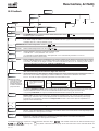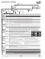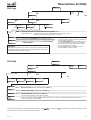
1
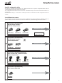
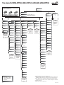
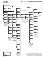
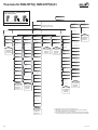
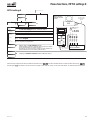
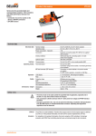
W .... ...... ...... ...... ..... ...... G ❏ NE lement to 990201-EN 3pp ❏ su ces 2.A12 la ✗❏ rep 2.+4.+6. A123 – MFT–H–2/ENG Operating Instructions MFT-H Handy for MFT/MFT2 actuators OEM Notes / Power supply ! Safety notes on using the MFT-H • When connecting-up to the actuator circuit, take great care not to allow the connecting lead to come into contact with mains power. Also ensure correct terminal assignment. • The MFT-H is not isolated electrically from the RS232 interface or the actuator. • Only approved computers that provide electrical isolation from the mains may be connected to the RS232 interface. • Use only leak-proof alkaline batteries of Size AA (Mignon, LR6: dimensions 50x14 mm) or suitable NiCd or NiMH rechargeable batteries. • All four units must be replaced at the same time when changing the batteries. • Ensure correct polarity when fitting the batteries. Always use four identical batteries of the same make and type. • Remove the batteries if the MFT-H is to remain unused for an extended period of time • The device contains no replaceable components apart from the batteries. Fitting the batteries 1. Turn the MFT-H over to expose the back. 2. Open the battery compartment with a screwdriver or coin. 3. Fit the batteries in the compartment as indicated by the markers and close the compartment again. Battery compartment Markers Actuators parameterisable with MFT-H All multifunctional and bus-capable actuators (MFT- / MFT2 actuators as well as the VAV compact NMV-D2M can be parameterised with the MFT-H. The damper actuator AM24-SR (multifunctional, but not bus-capable) can also be parameterised with the MFT-H. What do ‘MFT’ and ‘MFT2’ mean? MFT and MFT2 actuators employ Multi Function Technology and both types can be parameterised using the MFT-H Handy parameter assignment device. MFT(2) actuators can be controlled either conventionally or through the Belimo MP-Bus system. The actuator AM24-SR is not bus-capable. When used in a bus system each MFT / MFT2 actuator can also be linked to a sensor. The value provided by the sensor is acquired by the actuator and transferred to the MP-Bus system. MFT actuators can be linked to active sensors (DC 0-10 V output) and ON/OFF switches. MFT2 actuators can also be linked to passive resistance-type sensors (e.g. Pt 1000 devices). More information on sensor linking will be found in Product Information Document 2. + 6. MFT2-1. Important: Assigning parameters to MFT(2) damper actuators MFT(2) actuators (Multi-Function Technology) undergo basic parameter assignment for standard applications before being despatched from the factory. When necessary for his own purposes, the user can make on-site alterations to MFT(2) actuator parameters using the MFT Handy. However, when such reassignment of parameters is undertaken, the user will be responsible for ensuring that the settings are correct so as to provide proper functioning of the MFT(2) actuators. The final values of any new parameters should be marked on the MFT(2) actuators upon completion. 2 Vers. 2.0 Contents Brief description MFT-H Technical data /Accessoires 4 4 Connection options / Wiring 5 Powering up /down, Fault alarms 6 Using the tree-menus 7 Tree menu: NM24-MFT(2) AM24-MFT(2), AM24-SR GM24-MFT(2) 8 Tree menu: LF24-MFT(2) AF24-MFT(2) 9 Tree menu: NV24-MFT(2) NVF24-MFT(2) NVF24-MFT(2)-E 10 Tree menu: NMV-DM2 11 Description of menu functions Actuator A A1 Default functions 12-13 A2 Modify / A2.1 Control 14 A2 Modify / A2.2 Feedback 15 A2 Modify / A2.3 Motion 16 A2 Modify / A2.4 Copy A2 Modify / A2.5 Reset 17 17 A3 Service 18 MFT-H settings E 19 MP - adressing 20 Example of parameter assignment Example of an SRS function 21 Appendix Instructions for a Handy software upgrade Vers. 2.0 22-23 3 Brief description MFT-H / Technical data Operating controls Operating controls Action ➀ ON/OFF switch and Press to toggle On and Off Press for at least 2 s to illuminate display (MFT-H must be powered up first) display illumination 6 ➁ ESC Escape Key Press briefly once to move back one level in the menu Press for at least 2 s to return to the main menu ➂ SET Memory Key Jump to selected menu Enter selected command For moving the cursor to the next line or the previous line of the menu. When there are up to 3 selected steps per menu, the cursor will jump from line to line. When there are more than 3 selected steps it will scroll one line at a time each time a key is pressed. The longer the keys are held depressed the faster will be the scrolling. An audible signal is given when the last line of the menu is reached with the key pressed. MFT-H 5 ➃ Direction Keys ⑤ Direction Keys SET 4 3 ON 1 ESC OFF RS232 2 M 8 7 PP DC 24 V ➅ LCD Display ➆ RS232 connection 4-line Level converter PP or MP to RS232 Software upgrade MFT-H ➇ M Connection to MFT(2) actuator Parameter assignment by MFT-H MFT(2) actuators (Multi-Function Technology) undergo basic parameter assignment for standard applications before being despatched from the factory. When necessary, on-site alterations can be made to MFT(2) actuator parameters using the MFT-H Parameter Assignment Device. The kind of functions that can be set depends on the type of MFT(2) actuator being used. Technical data Power supply Minimum voltage Connections • Power and PP/MP • RS232 Display Communications Safety class For selecting steps in the menus when there are several side-by-side. Checking service functions with the MFT-H The MFT-H can be used for checking the functions of MFT(2) actuators. Either the values that have been previously assigned can be read out or the actuator itself can be operated with the MFT-H in order to check its functions. MFT-H 4 ordinary Mignon alkaline batteries 1.5 V, AA Size, LR6 or rechargeable NiCd batteries can be used An alarm appears on the display if the battery voltage falls below 4.2 V 3-pole motor plug-connector D-Sub 9 pole / female Operating the MFT-H No special knowledge of programming is needed. The device is used interactively by means of its 4-line display and keypad. The procedure is based on the menu method which guides the operator through the tree menu step-by-step. It almost completely eliminates any chance of making mistakes. In the various menus and sub-menus the operator can define the functions or parameters required. Implausible values will not be accepted by the MFT-H. The language of communication to be used by the device can be preselected. Tree menu (principle) ON OFF LCD 4-line PP/MP III (safety extra-low voltage) ABS plastic (210 x 100 x 50 mm) Weight 350 g Accessories included MFT-H – SET • • • • • Addressing Address Default functions Modify Service 1 Special adapter with compression terminals, type MFT-C 1 Motor connecting lead, 2-pole with motor plug-connector and two 4 mm dia. plugs 1 Power pack 24 V, type ZN230-24 4 Mignon alkaline batteries 2 Sheets of labels with 48 stickers on each (Item No. 31720) incl. Waterproof felt-tip pen Optional (Not included in the MFT-H - SET) Motor plug-connector, 3-pole for customised connecting lead, Item No. 11783 4 MFT-H settings Actuator Ambient temperature range 0 °C...+50 °C Maintenance Maintenance-free Case Menu selection The MFT-H as level converter The MFT-H can be used as a level converter between RS 232 and PP interfaces (ZIP function). Vers. 2.0 Connection options, Wiring ~ T - + AC 24 V DC 24 V Diagram 1 Typical application: For assigning parameters to an MFT(2) actuator when it is already connected into the overall system. In this application the actuator is under analogue control through the Y-signal. Connect through safety transformer ! _______________ _______________ _______________ _______________ Y U5 MFT-H Notes: • The MFT-H receives power from its own batteries. • The MFT(2) actuator receives power from the overall system. • The MFT(2) actuator is operable. • As long as the U/PP terminal of the MFT(2) actuator is connected to the MFT-H, the feedback signal U5 will not correspond to the instantaneous actual value. SET Installer’s connecting terminals Not included with MFT-H ON 1 2 3 ESC OFF 5 M RS232 + Y U MP ...-MFT(2) Z PP T ~ T - _______________ _______________ _______________ _______________ Special adapter MFT-C with compression terminals an jack ~ DC 24 V 1 U for DC 24V for AC 24V not assigned PP SET Jack stereo / 3,5 mm dia. / 3-pole ON 1 2 3 T ~ Y U MP ...-MFT(2) Z + Transformer or 24 V power 5 2 for DC 24V for AC 24V - MFT-H 5 ESC OFF RS232 PP + DC 24 V T UK24LON ~ T LONWORKS AC 24 V DC 24 V MP-Bus MFT-H ~/+ 24 V MP M Diagram 2 Typical application: For assigning parameters to an MFT(2) actuator before it is connected into the overall system. Suitable as well for assigning the same parameters to several MFT(2) actuators. Notes: • The MFT-H receives power from its own batteries. • The MFT(2) actuator receives power from the MFT-H during parameter assignment. • The MFT(2) actuator is only fully operable when it is receiving an external supply of power via the jack. • Providing an external supply of power to the MFT(2) actuator via the special adapter greatly extends the life of the MFT-H batteries. Diagram 3 Typical application: For assigning parameters to an MFT(2) actuator when it is connected together with other actuators (up to a total of 8) via an MP-Bus system to a UK24LON unit. In this application the MFT(2) actuators are controlled digitally over the MP-Bus. Notes: • The MFT-H receives power from its own batteries. • The MFT(2) actuators receive power via the UK24LON unit. • Use the MFT-H to select MP addresses 1...8 in order to gain direct access to the required actuator. T MFT(2)-Actuators 1 Vers. 2.0 2 3 4 5 6 7 8 5 Powering up/down, Fault alarms Powering up/down When an MFT-H Handy is powered up it is first initialised and the version of software with which it is loaded is displayed. BELIMO MFT-H Version 2.0 Initialising The subsequent behaviour of the Handy varies according to whether it is a first commissioning or a restart: First power-up/First commissioning: When a Handy is powered up for the first time it jumps directly to the “Language” menu after initialising. This allows the appropriate language of use to be selected. Restart: – on the same actuator: When the Handy is powered up again it jumps to the same menu item that it was at before it was powered down, provided it is connected to the same actuator as before (i.e. the Serial No. and Address correspond). – on a different actuator: If a different actuator is connected to the Handy before it is powered up again the fault alarm “No actuator” appears on the display and an audible beep signal is given. If the actuator has already been addressed, enter the correct address under “Search” on the menu and the Handy will find the actuator in question. Otherwise it will first be necessary to assign an address to the actuator; see “Addressing”, Page ... . Language > Deutsch English Cancel Menu > Actuator MFT settings Adressing No actuator > Search ...MFT-H settings Adressing Auto power-down: If, when a Handy is in use, none of its keys is pressed for a period of 5 minutes, it will power down automatically. Fault alarms Any faults that occur are always identified by an alarm on the display and also by an audible beep signal. Alarms for exhausted batteries When its batteries become exhausted (<4.2 V) the Handy generates an alarm on its display in the form of a flashing battery symbol. In order to avoid any loss of data the batteries must be replaced without delay. Replace batteries ! If necessary, the alarm signal can be acknowledged with the SET key so that any parameter assignment task that has been started can be completed first. Although the status message will disappear from the display the battery symbol will continue flashing. If the batteries are not replaced the fault alarm will appear again as soon as the Handy is powered up again. Communication and system fault alarms Message Possible causes of faults Fault rectification No actuator No reply from actuator Wiring error • Check wiring • Check address • Repeat command MFT(2) actuator defective Change MFT(2) actuator Defective transmission Programming error No EEPROM access Command not recognised Enter password: .... Access denied 6 MFT-H software version does not match Ascertain software versions of MFT-H and MFT(2) actuator and that of the MFT(2) actuator consult Belimo Input is password-protected Enter password and start Belimo-barred input Contact Belimo Vers. 2.0 Using the tree-menus Specific configuration table According to the particular application each MFT(2) actuator has a specific configuration table and the corresponding preset values stored in its memory. This configuration determines which menu items in the MFT-H Handy can be selected and which values can be modified. As soon as the Handy is connected to an MFT(2) actuator it downloads the data configuration from the actuator. Four different tree-menus For parameter assignment purposes there are four different tree-menus available for different groups of products which the user can turn to for assistance when he is parameterising a particular actuator: Tree-menu for parameterising MFT(2) damper actuators without a safety function 1 Tree-menu see page 8 NM24-MFT(2) 8 Nm AM24-MFT(2) GM24-MFT(2) 18 Nm 36 Nm Tree-menu also valid for AM24-SR Tree-menu for parameterising MFT(2) damper actuators with a safety function 2 Tree-menu see page 9 LF24-MFT(2) AF24-MFT(2) 4 Nm 15 Nm Tree-menu for parameterising MFT(2) valve actuators NV… without and NVF… with a safety function 3 Tree-menu see page 10 NV24-MFT(2) NVF24-MFT(2) NVF24-MFT(2)-E 800 N 800 N 800 N Tree-menu for parameterising VAV-Compact NMV-D2M 4 Tree-menu see page 11 NMV-D2M 8 Nm Vers. 2.0 7 Tree menu for NM24-MFT(2), AM24-MFT(2), AM24-SR, GM24-MFT(2) Tree-menu for parameterising MFT(2) damper actuators without a safety function and for the AM24-SR Menu selection Actuator NM24-MFT(2) AM24-MFT(2) GM24-MFT(2) 8 Nm 18 Nm 36 Nm Modify Default functions MFT-H settings Select MP-address 1–8. PP when only 1 actuator. Select PP for the AM24-SR! Address Service Language Addressing ➄ Address German SR (DC 2…10 V) Control Feedback Motion Copy Reset Identification English PWM (0.59-2,93s) DC control Torque Voltage U Enter original Last entry Serial No. Description of individual functions page 20 further languages in preparation 3-point Open/Close DC 2 – 10 V DC 2 – 10 V (Default) (Default) DC 0 – 10 V DC 0 – 10 V 100 % Description of individual functions pp. 12 & 13 DCV variable Start …… Stop …… PWM control 0.02 – 5s 0.59 – 2.93s 0.1 – 25.5s PWM variable DCV variable Start …… Stop …… Softswitch S ➁ S1 …… S2 …… Alarms (S; W; –) Stop/Go-Ratio Mech. Overload ➁ PW min PW max …… …… 3-point Open/Close Description of individual functions page 14 Travel ➁ Alarms & U Alarms & S 50 % 25 % ➃ Running time Standard variable …s 100% rotation CW or CCW ➂ ➂ Normal Description of individual functions page 17 Description of individual functions page 17 Typ/ SW version Plant site ……… Reference/Actual value Adapte Function info Data log ➀ Alarms further languages in preparation further languages in preparation further languages in preparation further languages in preparation further languages in preparation further languages in preparation further languages in preparation Delete PP-interface Function test Software Sensitivity SW-Version SW version Reverse Normal (Default) Rotation ➁➁ Minimum Description of individual functions page 15 All entries 75 % ➃ VAV (6 ± 4 V) copy Reduced Synchronisation Rotation …% Normal Intermediate Sync. at 0% Rotation …% Sync. at 100% Description of individual functions page 19 Maximum Rotation …% Description of individual functions page 18 Adaption Off (Default) Manual Auto Menu does not appear when “VAV (6 ± 4 V)” is selected under Basic Functions! 8 Description of individual functions page 16 ➀ Operating time, active time, Stop/Go ratio ➁ When the angle of rotation is limited mechanically the angle must be adapted electronically in order to ensure the proper functions ➂ HW + SW direction of rotation changes produce virtual changes for switching points and Z control (= position settings are reversed) ➃ Not for AM24-SR ➄ AM24-SR cannot be addressed Vers. 2.0 Tree menu for LF24-MFT(2), AF24-MFT(2) Tree-menu for parameterising MFT(2) damper actuators with a safety function Menu selection Actuator LF24-MFT(2) AF24-MFT(2) 4 Nm 15 Nm Address MFT-H settings Select MP-address 1–8. PP when only 1 actuator. Modify Default functions Service Language Addressing Address German SR (DC 2…10 V) Control Feedback Motion Copy Reset Identification English PWM (0.59-2,93s) DC control Torque Voltage 0 Enter original Last entry Serial No. Description of individual functions page 20 further languages in preparation 3-point Open/Close VAV (6 ± 4 V) Description of individual functions pp. 12 & 13 DC 2 – 10 V DC 2 – 10 V (Default) (Default) DC 0 – 10 V DC 0 – 10 V DCV variable Start …… Stop …… PWM control 0.02 – 5s 0.59 – 2.93s 0.1 – 25.5s PWM variable DCV variable Start …… …… …… 3-point Open/Close Description of individual functions page 14 ** Cannot be modified. Spare menu item. Stop …… Softswitch S ➁ S1 …… S2 …… Alarms (S; W; –) Stop/Go-Ratio Mech. Overload ➁ PW min PW max ** Cannot be modified Travel ➁ Alarms & U Alarms & S Description of individual functions page 17 All entries Description of individual functions page 17 Typ/ SW version Plant site ……… Reference/Actual value Adapte Running time Standard variable …s 100% rotation CW or CCW ➂ ➂ Normal Function-info Data log ➀ Alarms further languages in preparation further languages in preparation further languages in preparation further languages in preparation further languages in preparation further languages in preparation further languages in preparation Delete PP-interface Function test Software Sensitivity SW-Version SW version Reverse Normal (Default) Rotation ➁➁ Minimum Description of individual functions page 15 copy Reduced Synchronisation Rotation …% Normal Intermediate Sync. at 0% Rotation …% Sync. at 100% Description of individual functions page 19 Maximum Rotation …% Description of individual functions page 18 Adaption Off (Default) Manual Auto Menu does not appear when “VAV (6 ± 4 V)” is selected under Basic Functions! Vers. 2.0 Description of individual functions page 16 ➀ Operating time, active time, Stop/Go ratio ➁ When the angle of rotation is limited mechanically the angle must be adapted electronically in order to ensure the proper functions ➂ HW + SW direction of rotation changes produce virtual changes for switching points and Z control (= position settings are reversed) 9 Tree menu for NV24-MFT(2), NVF24-MFT(2)(-E) Tree-menu for parameterising MFT(2) valve actuators NV… without and NVF… with a safety function Menu selection NV24-MFT(2) 800 N NVF24-MFT(2) NVF24-MFT(2)-E 800 N Actuator 800 N Address MFT-H settings Select MP-address 1–8. PP when only 1 actuator. Modify Default functions Service Language Addressing Address German SR (DC 2…10 V) Control Feedback Motion Voltage U Force Copy Reset Identification English PWM (0.59-2,93s) DC control Enter original Last entry Serial No. ➁ 3-point Description of individual functions pp. 12 & 13 DC 2 – 10 V DC 2 – 10 V (Default) (Default) DC 0 – 10 V DC 0 – 10 V DCV variable Start …… Stop …… PWM control 0.02 – 5s 0.59 – 2.93s 0.1 – 25.5s PWM variable PW min PW max …… …… 3-point DCV variable Start …… Stop …… Softswitch S S1 …… S2 …… Alarms (S; W; –) Mech. Overload Travel Alarms & U Alarms & S 100 % 25 % Running time Standard variable …s 100% Range Direction of lift ➂ ➂ Normal Description of individual functions page 15 copy All entries Description of individual functions page 17 Description of individual functions page 17 Typ/ SW version Plant site ……… Reference/Actual value Adapte Function info Data log ➀ Alarms further languages in preparation further languages in preparation further languages in preparation further languages in preparation further languages in preparation further languages in preparation further languages in preparation Delete PP-interface Function test Software Sensitivity SW-Version SW version Reverse Normal (Default) Valve stroke Description of individual functions page 14 further languages in preparation 75 % 50 % Description of individual functions page 20 Reduced Minimum Valve stroke …% Description of individual functions page 19 Description of individual functions page 18 Intermediate Valve stroke …% Maximum Valve stroke …% Description of individual functions page 16 10 ➀ Operating time, active time, Stop/Go ratio ➁ With NVF... actuators the actuating force cannot be modified (the appropriate menus do not appear). ➂ HW + SW direction of rotation changes produce virtual changes for switching points and Z control (= position settings are reversed) Vers. 2.0 Tree menu for NMV-D2M (MFT) Tree-menu for parameterising VAV-Compact NMV-D2M Menu selection Actuator NMV-D2M 8 Nm Address MFT-H settings Select MP-address 1–8. PP when only 1 actuator. Modify Default functions Service Language Addressing Address German SR (DC 2…10 V) Control Control Feedback Motion Copy Reset Identification English DC control Description of individual functions pp. 12 & 13 Torque Voltage U Enter original Last entry Serial No. Description of individual functions page 20 further languages in preparation DC 2 – 10 V DC 2 – 10 V (Default) (Default) DC 0 – 10 V DC 0 – 10 V DCV variable Start …… Stop …… Description of individual functions page 14 DCV variable Start …… Stop …… Description of individual functions page 15 100 % copy 75 % 50 % 25 % Running time ➆ Standard Variable …s 100% Range CW or CCW ➂ ➂ Normal Description of individual functions page 17 All entries Reset original Description of individual functions page 17 Typ/ SW version Plant site ……… Reference/ Actual value ➅ Adapte Function info Data log ➀ Alarms further languages in preparation further languages in preparation further languages in preparation further languages in preparation further languages in preparation further languages in preparation further languages in preparation Delete PP-interface Function test Software Sensitivity SW-Version SW version Reverse Normal (Default) Volumetric flow ➁ Reduced Minimum Volumetric flow …% Description of individual functions page 19 Description of individual functions page 18 Intermediate Volumetric flow …% Maximum Volumetric flow …% Adaption Off (Default) Manual Auto Description of individual functions page 16 Vers. 2.0 ➀ Operating time, active time, Stop/Go ratio ➁ When the angle of rotation is limited mechanically the angle must be adapted electronically in order to ensure the proper functions ➂ HW + SW direction of rotation changes produce virtual changes for switching points and Z control (= position settings are reversed) ➃ Settings for the electrical working range for volumetric flow. ➄ Settings for the U5 voltage signal output for 0...100% nominal volumetric flow. ➅ Reference value and actual value as % of nominal volumetric flow. Calculation of actual volumetric flow [m3/h]: VACT [m3/h] = VNOM- [m3/h] / 100 x VACT [%] ➆ The set value of running time has no effect on normal control. Settings are only active for override control. 11 Menu functions, A1 Default functions Menu selection Actuator A Address Select MP-address 1–8. PP when only 1 actuator. Addressing MFT-H setting MP E Service Modify A1 SR (DC 2…10 V) A1.1 PWM (0.59-2.93s) A1.2 3-point A1.3 Open/Close A1.4 VAV (6 ± 4 V) A1.5 A2 A1.1 Default function SR (DC 2...10 V) Selecting this function parameterises the MFT(2) actuator for the modulating mode. Default functions >SR(2-10V DC ) PWM(0.59-2.93s) 3-point Display Wiring diagram SR AC 24 V ~ T - 2 + 3 AC 24 V t 0,59-2,93 s U5 Y U PP …-MFT.. Z Data record SR (DC 2...10 V) (Example AM24-MFT(2)) 12 Wiring diagram PWM DC 0...10 V DC 2...10 V 5 Working range Function Feedback U5 Torque Angle of rotation Running time Angle of rotation adaption Overrides (referred to full angle of rotation 95°) Default functions SR(2-10V DC ) >PWM(0.59-2.93s) 3-point 2...10 V DC 2...10 V DC 18 Nm min. 95° 150 s none Min. (min. position) = 0% IP (intermediate position) = 50% Max. (max. position) = 100% DC 2...10 V Display Example 1, 100% angle of rotation When a pulse of 2.93s duration is sent to the actuator it causes it to move to the 100% angle-of-rotation position. (If the pulses sent to the actuator are of longer duration than 2.93 s the actuator will also move to the 100% angle-of-rotation position). Example 2, 50% angle of rotation When a pulse of 0.59s + (2.93s - 0.59s) / 2 = 1.17 s + 0.59 s duration is sent to the actuator it causes it to move to the 50% angle-of-rotation position. Example 3, 0% angle of rotation When a pulse of 0.59 s duration is sent to Y U the actuator it causes it to move to the 0% - + Z PP …-MFT.. angle-of-rotation position. (If the pulses sent to the actuator are of shorter duration Explaining PWM control: than 0.59s but longer duration than 20 ms PWM does not mean ‘pulse width modu- the actuator will also move to the 0% lation’ in its normal sense. The actuator angle-of-rotation position; at less than measures the length of the control pulse 20 ms there is no defined function). and then moves to the corresponding position. So far, PWM-type actuators are Data record PWM (0,59-2,93s) (Example AM24-MFT(2)) only being used in the USA. Depending on Control signal Y PWM 0.59-2.93s the type of actuator, the user can define Working range Function various PWM ranges. 1 2 T T 1 MP1 A1.2 Default function PWM (0.59-2.93s) Examples of PWM control when a PWM Selecting this function parameterises the range of 0.59-2.93s has been selected for the actuator: MFT(2) actuator for the PWM mode. ~ ~ + DC 24 V Y U5 A3 T - Address ~ Default functions In the Default functions branch of the tree menu it is possible to assign so-called ‘default’ or standard functions to MFT(2) actuators. For each default function a data record containing the normal standard parameters for the function is stored. The appropriate function can be selected with the direction keys. Pressing the SET key enters the function into the actuator together with its data record. A warning appears on the display first which must be acknowledged by pressing the SET key again. 3 5 Feedback U5 Torque Angle of rotation Running time Angle-of-rotation adaption 2...10 V DC 18 Nm min. 95º 150 s none Vers. 2.0 Menu functions, A1 Default functions Wiring diagram Open/Close T - T ~ Y - + U PP …-MFT.. 2 3 Y U PP …-MFT.. Z - + w1 DC 0...10 V U5 DC 2...10 V 1 5 1 5 Z AC 24 V + DC 24 V DC 2...10 V T T 3 U5 2 3 4 w1 5 6 7 U PP y z U5 Control signal Y Function Feedback U5 Torque Angle of rotation Running time Angle of rotation adaption Vers. 2.0 3-point DC 2...10 V 18 Nm min. 95° 150 s none DC 2...10 V 5 1 2 3 T Data record Open/Close (Example AM24-MFT(2)) Control signal Y Function Feedback U5 Torque Angle of rotation Running time Angle of rotation adaption VRD2 ~ Data record 3-point (Example AM24-MFT(2)) Display Wiring diagram VAV - ~ ~ 2 + DC 24 V DC 2...10 V U5 1 AC 24 V Default functions 3-point Open/Close >VAV (6±4V) T AC 24 V Display ~ Wiring diagram 3-point Default functions PWM(0.59-2.93s) 3-point >Open/Close ~ Display A1.5 Default function VAV (6 ± 4V) Selecting this function parameterises the MFT(2) actuator for the VAV control mode. T Default functions SR(2-10V DC ) PWM(0.59-2.93s) >3-point A1.4 Default function Open/Close Selecting this function parameterises the MFT(2) actuator for the Open/Close mode ~ A1.3 Default function 3-point Selecting this function parameterises the MFT(2) actuator for the 3-point control mode. Y U PP …-MFT.. Z Open/Close DC 2...10 V 18 Nm min. 95° 150 s none - + Data record VAV (6± 4V) (Example AM24-MFT(2)) Control signal Y Function Feedback U5 Operating range Torque Angle of rotation Running time Angle of rotation adaption From VAV controller DC 2...10 V 6± 4V 18 Nm min. 95° 150 s none 13 Menu functions, A2 Modify The Modify branch of the tree menu allows the values and functions of an MFT(2) actuator to be custom-parameterised when necessary (see p. 21 Example of parameter assignment). When the Modify branch of the menu is first entered it will always show the values and functions that were given to an MFT(2) actuator the last time it was assigned parameters. If a modification of a particular default function (A1.x) only involves changing a few individual values from their default settings, it is advisable to load the MFT(2) actuator with the appropriate default function (see page 12) before making the modification. A2.1 Control Menu selection Actuator A MFT-H settings Address Addressing E Default functions Modify A1 MP Service A2 A3 Feedback Motion A2.2 Control Copy A2.3 Reset A2.4 A2.5 A2.1 Control allows appropriate working ranges to be defined for control modes A2.1.1 Selection of modulating control: The settings correspond to the electrical working range for 0...100% angle of rotation or stroke, in the case of VAV-Compact NMV-D2M = 0...100% nominal volumetric flow (VNOM) effect on working range if MAX and/or MIN positions (see Page 16, A2.3.4) are selected. The working range corresponds to the control range set with the MIN and MAX positions. The set MIN position corresponds to the Start point of the working range. The set MAX position corresponds to the Finish point of the working range. (For the VAV-Compact NMV-D2M the MIN position corresponds to the minimum volumetric flow VMIN and the MAX position to the maximum volumetric flow VMAX) A2.1.1a Selection of a fixed working range DC 2...10 V (as per SR (DC 2-10 V) see page 12, Section A1.1) DC 0 – 10 V A2.1.1b Selection of a fixed working range DC 0.5...10 V DCV variable A2.1.1c Variable definition of a working range : • Start DC 0.5...30.0 V; Finish DC 2.5...32.0 V • For the VAV-Compact NMV-D2M : Start point DC 0...30.0 V and Finish point DC 2.0...32.0 V DC control DC 2 – 10 V (Default) Start …… Stop …… Finish must be at least 2 V above Start! A2.1.2 Selection of PWM control (MFT(2) actuator parameterised for PWM control) (see page 12, A1.2 Explaining PWM control) 0.02 – 5s A2.1.2a Selection of a fixed PWM working range of 0.02...5s 0.59 – 2.93s A2.1.2b Selection of a fixed PWM working range of 0.59...2.93s 0.1 – 25.5s A2.1.2c Selection of a fixed PWM working range of 0.1...25.5 PWM variable A2.1.1d Variable definition of a PWM working range: PWM control PWMmin. 0.02 s...... PWMmax. 50.00 s PWmin PWmax …… …… 3-point A2.1.3 Selection of 3-point control. MFT(2) actuator parameterised with data record for 3-point actuator (see page 13, Section A1.3) Open/Close A2.1.4 Selection of Open/Close control. MFT(2) actuator parameterised with data record for Open/Close actuator (see page 13, Section A1.4) The mode of control required is selected with the direction keys and a variable working range with the direction keys and . Pressing the SET key either causes the menu to jump to the next sub-menu or the selected values are entered into the actuator. 14 Vers. 2.0 Menu functions, A2 Modify Menu selection A2.2 Feedback Actuator A Address MFT-H settings Addressing E Default functions Modify A1 MP Service A2 A3 Control Motion Copy Reset A2.5 A2.4 A2.3 A2.1 A2.2 The Feedback branch of the tree menu allows the function of the 5 feedback signal to be defined. A2.2.1 Selection of feedback signal U5 as a modulating linear DC measured voltage: The defined signals correspond to 0...100% angle of rotation or stroke. For the NMV-D2M the signals correspond to the actual value of volumetric flow in 0...100% referred to VNENN. A2.2.1a Select a fixed range of DC 2...10 V DC 0 – 10 V A2.2.1b Select a fixed range of DC 0.5...10 V DCV variable A2.2.1c Variable definition of the DC measuring voltage signal: • Start DC 0.5… 8.0 V; Finish DC 2.5… 10.0 V • For the VAV-Compact NMV-D2M: Start point DC 0...8.0 V and Finish point DC 2.0...10.0 V Feedback Voltage U DC 2 – 10 V (Default) Start …… Stop …… Softswitch S ➁ U5 U5 5 U5 5 Finish must be at least 2 V above Start! A2.2.2 Select feedback signal U5 as softswitches S1 and S2. Referred to the effective mechanical angle of rotation or stroke of the MFT(2) actuator, it is possible to define 2 soft switching points (S1 and S2). The level of the DC voltage of U5 varies according to the angle of rotation or stroke executed and the S1 or S2 switching points reached. Actuator position below set value of S1 : Level U5 = constant DC 4 V Actuator position above set value of S1 and below set value of S2 : Level U5 = constant DC 7 V Actuator position above set value of S2 : Level U5 = constant DC 10 V S1 …… S2 …… A2.2.2a A2.2.3 Alarms Set softswitches S1 and S2 (adjustable 1...99%) Value of S2 must always be set at least 10% higher than value of S1. Assign maintenance or fault alarms to feedback signal U5. Various criteria that output a maintenance or fault alarm on U5 can be defined. Depending on whether maintenance or fault has been defined for the criteria A2.2.3a - A2.2.3d, U5 outputs a specific signal when one of the criteria occurs. ➁ When the angleof-rotation is limited mechanically (<95º) the angle must be adapted electronically in order to ensure the proper functions. U5 Signal for normal mode (no maintenance or fault alarm, level = constant DC 3 V) U5 Signal for maintenance alarm DC 5.5 V U5 Signal for fault alarm DC 8.5 V DC 3 V t t t Note: Any existing maintenance alarms will be cancelled when the MFT(2) actuator is disconnected from the power supply. However, maintenance alarms can also be cancelled with the MFT-H device (see page 18, Section A3.6). • Any existing fault alarms can only be cancelled with the MFT-H device (see page 18, Section A3.6) Stop/Go-Ratio A2.2.3a Criterion actuator hunting (typical cause: unstable control) selectable as maintenance or fault alarm. Stop/Go-ratio is the ratio [%] of active time to operating time (operating time = No. of hours actuator connected to power supply. Active time = No. of hours MFT(2) actuator in mechanical motion while connected to power supply). A maintenance or fault alarm is generated if the Stop/Go-ratio exceeds a value of 20% (see also explanations on page 18, Section A3.5 Data log) Mech. Overlast A2.2.3b Criterion mechanical overload (actuator stationary) selectable as maintenance or fault alarm. Travel A2.2.3c Criterion mechanical travel changed 10% selectable as maintenance or fault alarm. A2.2.4 Combination of maintenance or fault alarms A2.2.3a – A2.2.3d and modulating DC measuring voltages A2.2.1a – A2.2.2b selectable. If a maintenance or fault alarm criterion is exceeded, the DC measuring voltage signal ➁ ➁ Alarms & U for the maintenance or fault signal are overridden. Alarms & S A2.2.5 Combination of maintenance or fault alarms A2.2.3a – A2.2.3c and softswitches S1 and S2 A2.2.2a – A2.2.2b selectable. If a maintenance or fault alarm criterion is exceeded, the softswitch signals for the maintenance or fault signal are overridden. The feedback function required is selected with the directions keys and variable values are set with the direction keys and . Pressing the SET key either causes the menu to jump to the next sub-menu or the selected values are entered into the actuator. Vers. 2.0 15 Menu functions, A2 Modify Menu selection Actuator A Address MFT-H settings Addressing MP E Default functions Modify A1 Service A2 A3 Control Copy Feedback A2.2 A2.1 Motion Reset A2.4 A2.5 A2.3 The Motion branch of the tree menu allows the motion, running time and angle-of-rotation or stroke functions of the MFT(2) actuator to be defined. A2.3.1 Select the torque or force of the MFT(2) actuator (not possible in the case of MFT(2) actuators with springs) 100 % A2.3.1a Set torque or force to 100% (default value). Example: AM24-MFT(2) = 18 Nm 75 % A2.3.1b Set torque or force to 75% of default value. Example: AM24-MFT(2) = 13.5 Nm 50 % A2.3.1c Set torque or force to 50% of default value. Example: AM24-MFT(2) = 9 Nm 25 % A2.3.1d Set torque or force to 25% of default value. Example: AM24-MFT(2) = 4.5 Nm A2.3.2 Select running time of MFT(2) actuator Standard A2.3.2a Set running time for 100% angle of rotation or stroke as default value. Example: AM24-MFT(2) = 150 s Variable A2.3.2b Set running time for 100% angle of rotation or stroke anywhere within a range determinated. Note: The torque [Nm] and sound power level [dB] of the MFT(2) actuator might vary if the running time is less than the default value. Refer to the appropriate function graphs in the product information on MFT(2) actuators. The adjustable range of running time depends of the connected MFT(2) actuator. A2.3.3 A2.3.3a Select the direction of rotation or lift of the MFT(2) actuator. Set the direction of rotation or lift according to the symbols on the directionof-rotation switch on the housing of the MFT(2) actuator or the settings of DIL switch S3.2 (closing point) on the linear actuator. Torque Running time …s 100 % Rotation Direction of rotation or lift Normal Reverse Rotation A2.3.3b A2.3.4 ➁ Minimum RM with spindle extended ON 1 2 Y = 0 Closing point with spindle retracted 1 2 point Y = 0 Closing with spindle extended OFF ON 1 2 Y=0 Y=0 Y=0 * For damper actuators and valve actuators select override positions and/or angle-of-rotation or stroke limits. ** For the VAV-Compact NMV-D2M select override positions and volumetric flow limits. Enter the MIN position Adjustable: 0…100% referred to MAX position Note: For the VAV-Compact NMV-D2M: Set VMIN Adjustable: 0…100% referred to preset VMAX. angle of rotation. A2.3.4b Enter the intermediate position. Adjustable: 0…100% referred to the control range set with the MIN and MAX positions A2.3.4c Enter the MAX position Adjustable : 0...100% angle of rotation or stroke (in the case of the VAV-Compact NMV-D2M referred to the nominal volumetric flow VNOM). Rotation …% Adaption LM Y = 0 Closing point In the case of the AM24-SR and their configuration variants AM24-0xx the MIN position is referred to 0...100% Rotation …% Maximum 1 2 retracted RM (For detailed functional descriptions see Product Information Documents * 2. + 6. MFT(2)-1 or ** 4. NMV-D2M-1) A2.3.4a Rotation …% Intermediate Set the direction of rotation or lift opposite to the selected direction of rotation of the damper actuator or to the selected closing point of the linear actuator. Damper actuators Linear actuators NV, switch S3.2 Y = 0 Closing point OFF Y = 0 LM with spindle For the VAV-Compact NMV-D2M: Set VZS. Adjustable: 0…100% referred to the control range VMIN and VMAX. Note: In the case of actuators with a mechanically limited angle of rotation (<95°) the angle of rotation must be electronically adapted in order to ensure that the function is active (see also Document 2. + 6. MFT2-1) A2.3.5 Select adaption (during adaption the measuring signal U5 is automatically adapted to the effective value of mechanical angle of rotation. The working range and the running time are adapted to the control range set with MIN and MAX). (Default) A2.3.5a No adaption (default) Manual A2.3.5b To trigger adaption • NM24-MFT(2), AM24-MFT(2),GM24-MFT(2) and NMV-D2M by pressing the manual pushbutton twice. • LF24-MFT(2) and AF24-MFT(2) by moving the L/R switch back and forth twice. Auto A2.3.5c Adaption triggered: Each power-up or when the functions described in A2.3.5b are implemented. Off The functions required are selected with the directions keys and the variable values are set with the direction keys . Pressing the SET key either causes the menu to jump to the next sub-menu or the selected values are entered into the actuator. 16 Vers. 2.0 Menu functions, A2 Modify A2.4 Copy Menu selection Actuator E Address Default functions Modify A1 Addressing MFT-H setting A MP Service A2 A3 Feedback Control Copy ActuatorActuator Enter original copy A2.4 A2.4 A2.3 A2.2 A2.1 Copy Motion Copy data record from one MFT(2) actuator to another. Typical applications: • Replacing a mechanically-defective MFT(2) actuator with a new unit • Assigning parameters to a small series of actuators A2.4.1 Copying procedure: Enter data from Actuator 1 into the MFT-H device A2.4.2 Load data received from Actuator 1 into Actuator 2 or other actuators. Important The duplicating function can only be used if the type and the actuator configuration table are identical in both the original and the copy, otherwise a fault alarm will be given. A2.5 Reset 1. Connect the MFT-H device to the MFT(2) actuator from which the data is to be taken. 2. Use the ”Enter original” function on the MFT-H device to transfer the data from the actuator to the device. 3. Disconnect the MFT-H device from the first actuator and connect it to the next actuator. 4. Use the ”Copy” function on the MFT-H device to enter the data into the next actuator. Menu selection Actuator E Address Default functions Modify A1 Addressing MFT-H setting A MP Service A2 A3 Feedback Control A2.2 A2.1 Reset Reset Motion A2.3 A2.5 A2.5 Reset any entry already verified with the SET key. Last entry A2.5.1 Reset the last entry verified with the SET key. All entries A2.5.2 Reset all entries verified with the SET key since the last power-up of the MFT-H device. Reset Original In the case of VAV-Compact (NMV-D2M) resets VMIN, VZS and VMAX to the settings that were stored in the unit when it was delivered. The functions required are selected with the directions keys next sub-menu or the selected functions are initiated. Vers. 2.0 . Pressing the SET key either causes the menu to jump to the 17 Menu functions, A3 Servie Menu selection Actuator E Address Default functions Service Identification A1 Modify Addressing MFT-H setting A MP A2 A3 In the Service branch of the tree menu it is possible to initiate service functions and to assign parameters to them, as well as accessing specific system data. A3.1 Identification of the MFT(2) actuator. Serial-No. A3.1.1 Read out the Serial No. of the MFT(2) actuator. Typ + SW version A3.1.2 Read out the Type / Software version of the MFT(2) actuator. Plant site ……… A3.1.3 Display the plant site string (if available, otherwise no function). Reference/ Actual value A3.2 The actual position of the actuator as a percentage of the effective value of angle of rotation or stroke (actual volumetric flow Adaption A3.3 Initiate angle-of-rotation adaption. Adaption can be initiated by pressing the SET key. The MFT-H display verifies the initiation with the message ”Adaption in progress”. During adaption, the actuator runs automatically to both end positions. It adapts the U5 feedback signal to the effective mechanical angle of rotation. The running time and the working range are adapted to the control range defined by MIN and MAX. Function info A3.4 Display the actual parameters of the MFT(2) actuator (actual data record) as a percentage of the nominal volumetric flow in the case of the VAV-Compact NMV-D2M) can be compared with the reference value. It is important to take into account that, in the case of electronically limited angles of rotation (or limited volumetric flow with the NMV-D2M), i.e. set with MIN and MAX positions – see Page 16, para. A2.3.4 – the working range of the actuator depends on the set values of MIN and MAX (VMIN and VMAX with the NMV-D2M). The Start point of the working range is at the MIN position and the Finish point at the MAX position (VMIN and VMAX in the case of the NMV-D2M). In addition, it is important to take into account that the MIN position is referred to the MAX position (VMIN referred to VMAX in the case of the NMV-D2M). Function: Use the direction keys to move one display line forward or back. When a line contains several parameters (e.g. various defined maintenance alarms, see page 15), the MFT-H device scrolls automatically after a few seconds. Data log A3.5 Display Operating time [h], Active time [h] and Stop/Go-ratio [ratio of active time to operating time] Operating time = No. of hours actuator powered up. Active time = No. of hours actuator powered up and moving. Stop/Go-ratio = Ratio [%] of active time to operating time (calculate thus: active time [h] / operating time [h] x 100) Example: An operating time of 100,000 h and an active time of 10,000 h gives a Stop/Go-ratio of 10%. If the Stop/Goratio is relatively high it might be due to unstable control triggering the actuator. Page 15 (A2.2.3a) describes how the Stop/Go-ratio can be defined as a criterion for maintenance and fault alarms. Use the direction keys to move between operating time, active time and Stop/Go-ratio in the menu. Alarms A3.6 Display maintenance and fault alarms generated by the actuator. Whenever there are several alarms present, they can be displayed in succession by pressing the direction keys . Individual alarms can be cancelled by pressing the SET key. The message No alarms is displayed if there are no alarms present. Delete Function test A3.7 Note: During the function test the actuator must be receiving a 24 V AC power supply (see page 5, Diagram 1). Sensitivity Normal A3.8 Synchronisation Normal (Default) Sync. at 0% Sync. at 100% A simple GO/NO GO – test for functional testing. 1. When the menu is selected a reference value corresponding to the preset MAX position is issued to the actuator by the Handy (default for MAX is 100%). The actuator continues running until it reaches the preset reference value. 2. When the SET key is pressed the Handy issues the actuator with a reference value which corresponds to the preset MIN position (default for MIN is 0%). The actuator continues running until it reaches the preset reference value. 3. The next time the SET key is pressed the Handy issues the actuator with a reference value which corresponds to 50% of the control range defined by MIN and MAX. (The value is 50% if the MIN and MAX positions are set to default). The actuator continues running until it reaches the preset reference value. Note: The MIN position is referred to the preset MAX position. Response sensitivity and reversal hysteresis are adjustable so that MFT(2) actuators do not respond to every oscillatory movement of the control signal. The service life of the equipment can be enhanced by a correct choice of these values. The values are defined as degrees of angle of rotation in the case of rotary actuators and as mm in the case of linear actuators. The values correspond to the amount by which the control signal must be changed in order to change the position of the actuator. A3.8.1 Response sensitivity set to 1 degree (rotary actuators) or to 0.2 mm (linear actuators). (Default) Reduced S E Q U E N C E Reversal hysteresis set to 2.5 degrees (rotary actuators) or to 0.5 mm (linear actuators). A3.8.2 Settings for Response sensitivity set to 2 degrees (rotary actuators) or to 0.4 mm (linear actuators). sensitive equipment: Reversal hysteresis set to 5.0 degrees (rotary actuators) or to 1.0 mm (linear actuators). A3.9 Definition of Default position (synchronisation) A3.9.1 At initial commissioning, when the pushbutton is pressed, the actuator runs to depending on the direction of rotation selected (see Table). D of R switch L M Y=0 A3.9.2 At each power-up (also after a power failure) the actuator runs to default R M Y=0 position 1 or 2 depending on the direction of rotation selected (see Table). 1 default position or 2 A3.9.3 At each power-up (also after a power failure) the actuator runs to default position 3 or 4 Default positions 1 ccw 2 cw 3 cw 4 ccw Note: If the direction of rotation is software-reversed (A2.3.3b, page 16), the default positions will be opposite. depending on the direction of rotation selected (see Table). The functions required are selected with the directions keys and Pressing the SET key either causes the menu to jump to the next sub-menu or actuator data can be displayed, deleted or entered into the actuator. 18 Vers. 2.0 Menu functions, MFT-H settings E MFT-H settings E Menu selection Addressing Actuator Wiring diagram if MFT-H is used as ZIP A1 MFT-H settings E Various modes of operation can be selected from the MFT-H settings branch of the tree menu. E1 MFT-H language of communication A2 Service A3 PC D-Sub ! PP-Interface ready... >Abort Connect through safety transformer AC 24 V 1 2 3 T Language Modify T Default functions RS 232 - cable (not included in MFT-H) ~ A ~ Address MP - + DC 24 V MFT-H E1.1 Select German English E1.1 Select English further languages E1.3E1.10 currently in preparation SET ON OFF RS232 E2 MFT-H device in PP-Interface mode When the MFT-H device is switched to this mode, the display shows the message "PP-Interface ready....". The MFT-H can now be used as a level converter between an RS232 interface and a PP interface (ZIPfunction). 5 M D-Sub PP-interface ESC T German PP U PP MFT(2) actuator Software E3 Display of Software version loaded in MFT-H device SW-Version SW version The functions required are selected with the direction keys and the variable values set with the directions keys . Pressing the SET key either causes the menu to jump to the next sub-menu or the selected values are entered into the actuator. Vers. 2.0 19 MP-Addressing Menu selection Actuator A MFT-H settings E Addressing Addressing ➄ Address MP The address of the actuator is entered in the Addressing branch of the menu. MP1 Either PP or 1...8 (MP addresses) can be selected in the “Address” menu. • The PP address (PP = Point-to-Point) is selected if there is only one MFT(2) actuator connected to the Handy (see Diagram 1 or Diagram 2 on Page 5). When an actuator is addressed with PP it is automatically parameterised for the classic mode of operation (no MP-Bus). In this case its control in the classic mode can be either modulating, 3-point, Open/Close or PWM. PP addressing is also used to reset an actuator that has previously been set for bus operation to the classic mode. • MP addresses 1...8 (MP = Multi Point) is selected if there are several MFT(2) actuators connected to the Handy via the MP-Bus (see Diagram 3 on Page 5). This is because when there are several MFT(2) actuators communicating over the MP-Bus each one must be clearly identifiable. When an MFT(2) actuator is addressed with an MP address 1...8 it is automatically parameterised for MPBus operation. In this case it is controlled digitally over the MP-Bus. Procedure for addressing an MFT(2) actuator: 1. Preselect the required address with the keys (Example: MP address 4) Addressing >Addressing: 4 ESC = Abort 2. Press the SET key and the following display will appear… Addressing Unlatch actuator ESC = Abort 3. Perform the appropriate reset function on the MFT(2) actuator from the table below and according to what the Handy demands. Actuator family Actuator type Reset function Actuators without spring return NM24-MFT(2), AM24-MFT(2), GM24-MFT(2), NMV-D2M Press manual pushbutton 1x Actuators with spring return LF24-MFT(2), AF24-MFT(2) Move L/R switch back and forth 1x (within 4 s) R L Linear actuators for valves NV24-MFT(2), NVF24-MFT(2), Press key S2 1x NVF24-MFT(2)-E (inside the housing cover) 4. The following display appears briefly to show that the appropriate address has been assigned to the MFT(2) actuator: Actuator programmed… The required address will have been assigned to the actuator when this procedure has been completed. Menu selection ➄ Notes on parameterising AM24-SR’s The AM24-SR and its configuration variants AM24-xx (e.g. AM24-001) do not have a bus capability and so cannot be addressed. In order to set their parameters these types can be accessed directly via the Actuator/Address menu. In this case “PP” must be selected as the address. 20 Actuator MFT-H settings Address Select PP Basic functions Modification Service Vers. 2.0 Examples of parameter assignment Starting point for the examples of parameter assignment • When the MFT-H device is powered up, it always jumps directly to the menu step that was selected when it was powered down. In the following Examples, parameter assignment always begins in the main menu. Press the ESC key for at least 2 seconds in order to access the main menu. • During parameter assignment, the MFT(2) actuator must be connected to the MFT-H device as shown in Diagrams 1 or 2 (see page 5). Select menu >Actuator Data records MFT-H settings 1. Example: Parameterising an SRS function with a AM24-MFT(2) actuator 1.1 Preparation a) Definition of required parameters Press the SET key Working range DC 3.5...6.6 V Display 1: Function Feedback U5 Torque Angle of rotation Running time Angle-of-rotation adaption Overrides (referred to the full angle of rotation of 95°) DC 2...10 V min. 18 Nm 95° 150 s none Min. (Min.Pos.) = 0% IP (Intermediate Pos.) = 50% Max. (Max.Pos.) = 100% b) Ascertain default function nearest to the final parameterising required. To ascertain: The above data record is nearest to the default function SR (2...10 V DC). Therefore, the SR default function and the SR wiring diagram shown on page 12, Section A1.1 can be used as the basis. Actuator being programmed... during programming h) Selected DC variable menu Press the key twice until the cursor is opposite DC variable. Control signal DCV >DC 2-10 V DC 0-10 V >DCV variable Display Display 2: Default functions >SR (DC 2...10 V) PWM(0,59-2,93s) 3-point SR (DC 2...10V) programmed A 2-beep signal gives audible confirmation... Press the SET key DCV variable >Start Finish > 2.0V 10.0V ESC = Abort Display e) Select Modify menu Press the ESC key Actuator >Default functions Modify Service Display i) Program SRS range Hold the key depressed until Start shows 3.5 V. DCV variable >Start Finish > 3.5V 10.0V ESC = Abort Display Press the key 1.2 Parameter assignment a) Select menu Display Press the ESC for 2 seconds. Select menu >Actuator Data records MFT-H settings Display Actuator >Default functions Modify Service Actuator >Default functions Modify MFT-H settings Display Display Modify >Control Feedback Motion f) Select Control menu Press the SET key Control >Control signal DCV Control signal PWM 3-point c) Select Default functions menu Press the key Default functions >SR (DC 2...10 V) PWM(0,59-2,93s) SET 3-point Display d) Load default function SR (DC 2...10 V) into the MFT damper actuator. Press the Display SET key Modify overwrite? SET=Execute ESC=Abort g) Select Control signal DCV menu Press the SET key Display 1: during programming Display 2: Control signal DCV has been loaded.... Actuator being programmed... Control signal DC V >DC 2-10 V DC 0-10 V DCV variable A 2-beep signal gives audible confirmation... key DCV variable >Start Finish 3.5V >10.0V ESC = Abort Hold the key depressed until Finish shows 6.6 V. Display Display SET Display Press the SET key b) Select Actuator menu Press the SET key. Press the DCV variable >Start Finish 3.5V >6.6V ESC = Abort Press the SET key Display 1: during programming Display 2: Working range DC 3,5V-6.6 V programmed. Actuator being programmed... DCV variable >Start Finish 3.5V >6.6V ESC = Abort A 2-beep signal gives audible confirmation... k) Labelling: Upon completion of programming, attach a label to the MFT(2) actuator showing the customised data (not identical to the AM24-SR basic type). A waterproof felt-tip pen Working range = will write on the special DC (3,5 - 6,6V) stickers provided (use 2 stickers if necessary). Data record parameterised Vers. 2.0 21 Instructions for a Handy software upgrade Before a software upgrade can be carried out a binary file containing the whole menu and the languages (Version 2.0 has German and English only, other languages are in preparation) must be loaded into the Handy. Use the “download20.exe” download program for this purpose. The program can be started directly from the floppy disk (1.44 MB) or the hard disk. System requirements and accessories needed: • PC with Windows 95/98/NT/2000 and at least 8 MB of RAM • Available serial interface COM1 or COM2 • Mouse for operating the software • RS232 lead, for monitors, D-Sub 9-pin, male/female (no core crossing) Procedure for upgrading MFT-H Handy’s: Remove the red cap from the interface connector on the Handy and use the 9-pin D-Sub lead to connect to one of the PC’s serial interfaces COM1 or COM2. Start the download program download20.exe from the hard disk or floppy and activate the appropriate interface, e.g. COM2. In the menu, click on [Download] [Load file] or and .... ....open the binary file, e.g. <<mft-h-v20.bin>> The file will have been loaded successfully if the <<ready to program>> message appears. 22 Vers. 2.0 Instructions for a Handy software upgrade Preparing the Handy Switch on the Handy and wait until it has finished its startup cycle (first-time Handy’s jump to [Language] in the menu. No actuator Search Data records >MFT-H settings Select [MFT-H settings] in the menu and change to the [Software] menu. Pressing all 4 arrow keys on the Handy at the same time for at least two seconds will cause the display to change to the hidden menu [SW Upgrade]. Select [Execute] Note: Activating “Execute” deletes the old software immediately. This means that the Handy can no longer be used until the new software has been loaded. Loading a Handy with its new software The message below and a flashing arrow (bottom right) indicate that the Handy is ready for the software download. Downloading is started by using the mouse to click on [Download] and then [Start] or . Download status is indicated at ‘Progress’ by means of a moving bar. While this function is in progress a solid square in the bottom right-hand corner of the Handy display will be flashing. Wait until the following status message appears (this may take a few minutes): MFT-H settings Language PP-Interface >Software Software V1.0 26.03.98 >Cancel SW-Upgrade >Execute Cancel SW-Upgrade Ready... < The Handy has now been successfully upgraded. It will then restart, give a single short beep and change to the Start Menu. Programming other Handy’s If there are other Handy’s to be upgraded with new software simply plug in the next one with the RS232 lead and proceed again as described above. Errors during upgrading Should downloading be impossible for any reason the following status message will appear on the display: Check the following points: • Is there a proper connection between the Handy and the appropriate serial interface COM1 or COM2? • Are you sure there is really no core crossing in the RS232 lead? • Is the Handy switched on and in SW Upgrade mode? (Is the arrow in the bottom righthand corner of the display flashing?) If everything appears to be OK, click on [Start] in the [Download] menu again. If it still does not work, switch the Handy off and on again, close the download software on the PC and restart it. Vers. 2.0 23 Air applications Standard actuators and spring-return actuators for air control dampers in HVAC systems Water applications Safety actuators for motorizing fire and smoke extraction dampers VAV systems for individual room air control Mixing actuators and motorized ball valves for HVAC water circuits Globe valves and intelligent linear actuators – also for leading makes of valve Innovation, Quality and Consultancy: A partnership for motorizing HVAC actuators Belimo Headquarters CH BELIMO Holding AG Brunnenbachstrasse 1 8340 Hinwil, Switzerland Tel. +41 (0)43 843 61 11 Fax +41 (0)43 843 62 68 [email protected] www.belimo.ch Belimo Subsidiaries AT/ BELIMO Automation HR/ Handelsgesellschaft m.b.H. HU/ Geiselbergstrasse 26–32 SI/ 1110 Wien, Austria SK Tel. +43 (0)1 749 03 61-0 Fax +43 (0)1 749 03 61-99 [email protected] AU CA CH DE ES BELIMO Actuators Pty. Ltd. Unit 10, 266 Osborne Avenue Clayton South, VIC 3169 Australia Tel. +61 (0)3 9551 0201 Fax +61 (0)3 9551 0215 [email protected] BELIMO Aircontrols (CAN), Inc. 5716 Coopers Ave., Units 14&15 Mississauga, Ontario L4Z 2E8 Canada Tel. +1 (1)905 712 31 18 Fax +1 (1)905 712 31 24 [email protected] BELIMO Automation AG Sales Switzerland Brunnenbachstrasse 1 8340 Hinwil, Switzerland Tel. +41 (0)43 843 62 12 Fax +41 (0)43 843 62 66 [email protected] www.belimo.ch BELIMO Stellantriebe Vertriebs GmbH Welfenstr. 27, Postfach 72 02 30 70599 Stuttgart, Germany Tel. +49 (0)711 1 67 83-0 Fax +49 (0)711 1 67 83-73 [email protected] www.belimo.de BELIMO Ibérica de Servomotores, S.A. C/San Romualdo, 12–14 28037 Madrid, Spain Tel. +34 91 304 11 11 Fax +34 91 327 25 39 [email protected] FR BELIMO Servomoteurs Z.A. de Courtry 33, Rue de la Régale 77181 Courtry, France Tél. +33 (0)1 64 72 83 70 Fax +33 (0)1 64 72 94 09 [email protected] BG BELIMO Bulgaria Ltd. j.k. Lagera, 3 Smolyanska Str. bl. 56, entr. B, ap. 50 1612 Sofia, Bulgaria Tel. +3592 952 3470/1 Fax +3592 545 995 [email protected] IE Safegard Systems Ltd. Systems House, Unit 34 Southern Cross Business Park Bray, Co Wicklow, Ireland Tel. +353 (0)1 2761600 Fax +353 (0)1 2761611 [email protected] PH BELIMO Actuators Philippines Rm.# 507 Anita Build., 5th Floor 1300 Quezon Ave.,Cor.South Ave. 1103 Quezon City, Philippines Tel. +63 (2)373 5440 Fax +63 (2)373 5424 [email protected] BELIMO Automation UK Limited CN The Lion Centre Hampton Road West Feltham, Middlesex, Great Britain TW 13 6DS Tel. +44 (0)20 8755 4411 Fax +44 (0)20 8755 4042 [email protected] CN HK BELIMO Actuators Ltd. Room 208, 2/F New Commerce Centre 19 On Sum Street, Shatin, N.T. Hong Kong Tel. +852 26 87 17 16 Fax +852 26 87 17 95 [email protected] CY PL BELIMO Silowniki S.A. ul. Zagadkl 21 02-227 Warszawa, Poland Tel. +48 (0)22 886 53 05 Fax +48 (0)22 886 53 08 [email protected] CZ SG BELIMO Actuators Pte Ltd 2, Jurong East Street 21 #04-31F IMM Building Singapore 609601 Tel. +65 6564 9828 Fax +65 6564 9038 DK [email protected] BELIMO Actuators Ltd. Room 1305, Financial Square No. 333 Jiujiang Road 200001 Shanghai, China Tel. +86 21 6360 8980 Fax +86 21 6360 8981 [email protected] IL Shemer Representations P.O. Box 296 56101 Yehud, Israel Tel. +972 3 536 51 67 Fax +972 3 536 05 81 [email protected] RO SC Mano Construct srl Str. Cameliei nr 5, sector 1 Bucuresti, Romania Tel. +40 212 126 993 Fax +40 212 126 995 [email protected] RU BELIMO Servomotors Russia Ltd. Nizhnyaya Pervomaiskaya, 46 Bld.1, Office 303 105203 Moscow, Russia Tel. +7 095 965 74 64 Fax +7 095 965 74 73 [email protected] SE BELIMO AB Hägerstens Allé 88 129 37 Hägersten, Sweden Tel. +46 (0)8 464 07 00 Fax +46 (0)8 97 85 75 [email protected] SY Philippe A. Jebran P.O. Box 7791 Damascus, Syria Tel. +963 11 231 6586 Fax +963 11 231 4052 [email protected] TR BELIMO Otomasyon A.S. Keyap Sitesi No. 20 TR-34775 Y. Dudullu Istanbul, Turkey Tel. +90 (0)216 527 98 70 Fax +90 (0)216 527 98 71 [email protected] TW Chianseng Enterprise Co. Ltd. 2F, No. 21, Tong Fong Street Taipei, Taiwan Tel. +886 2 27 08 77 80 Fax +886 2 27 02 90 90 [email protected] UA BELIMO Ukraine S.A.R. 34-A, Ul. Yurkovskaya, Appt.No 2 254080 Kiev, Ukraine Tel. / Fax +380 44 463 7586 [email protected] ZA BELIMO Actuators Southern Africa cc P. O. Box 2483 Alberton 1450, South Africa Tel. +27 (0)11 868 5681 Fax +27 (0)11 900 2673 [email protected] GB US BELIMO Aircontrols (USA), Inc. 43 Old Ridgebury Road P.O. Box 2928 Danbury, CT 06810 USA Tel. +1 (1)203 791 99 15 Fax +1 (1)203 792 29 67 [email protected] www.belimo.com Belimo Representatives and Agencies AE BELIMO Trading Middle East Office P.O. Box 73885 Dubai, U.A.E. Tel. +971 (0)4 295 9670 Fax +971 (0)4 295 9680 [email protected] IN BELIMO Beijing Rm 605, Beijing Hai Chang Edifice, 44, Liang Ma Qiao Road Chao Yang District 100016 Beijing, China Tel. +86 10 6462 1382 Fax +86 10 6462 1383 [email protected] BELIMO Vitek Air Controls C-114 Lancelot, First Floor S.V. Road, Borivali (West) Mumbai 400 092, India Tel. +91 22 5695 9439 Fax +91 22 2806 2163 [email protected] IS R.E.S. Ltd. P.O. Box 8297 Nicosia, Cyprus Tel. +357 (0)2 51 10 07 Fax +357 (0)2 49 65 47 [email protected] Hitatækni ehf. Langholtsvegi 109 104 Reykjavik, Iceland Tel. +354 5 88 60 70 Fax +354 5 88 60 71 [email protected] IT BELIMO CZ (Ing. Ivar Mentzl) Charkovská 16 10100 Praha 10, Czech Republic Tel. +420 (0)2 717 4 0 311 Fax +420 (0)2 717 43 057 [email protected] KR BELIMO A/S Thomas Helstedsvej 7A 8660 Skanderborg, Denmark Tel. +45 86 52 44 00 Fax +45 86 52 44 88 [email protected] EE BELIMO Balticum AS Türi 10 d 11313 Tallinn, Estonia Tel. +372 6 140 811 Fax +372 6 140 812 [email protected] FI Oy Suomen BELIMO Ab Insinöörinkatu 2 00810 Helsinki, Finland Tel. +358 (0)424 651 1 Fax +358 (0)424 651 250 [email protected] GR BELIMO Air Controls 29, Tagm. Plessa, Kallithea GR 17674 Athens, Greece Tel. +30 2 10 94 00 766 Fax +30 2 10 94 00 767 [email protected] LB BELIMO Servomotori S.r.l. Via Stezzano, 5 24050 Zanica BG, Italy Tel. +39 035 67 26 82 Fax +39 035 67 02 00 [email protected] HANMO Corporation 3rd Floor, Yeosam Bldg. 648-23 Gangnam-Ku, Seoul, Korea Tel. +822 3453 8225 Fax +822 3453 8228 Energy Center (EC) Hamra, Leon Street, Shatilla, Bldg. 4th Floor, P.O. Box 113-6955 Beirut, Lebanon Tel. +961 (0)1 35 38 23 Fax +961 (0)1 35 38 23 [email protected] NL / BELIMO Servomotoren BV BE / BENELUX LU Postbus 300, 8160 AH Epe Radeweg 25, 8171 MD Vaassen Netherlands Tel. +31 5 78 57 68 36 Fax +31 5 78 57 69 15 [email protected] NO BELIMO Spjeldmotorer A/S Konowsgate 5 0192 Oslo 1, Norway Tel. +47 22 70 71 71 Fax +47 22 70 71 70 [email protected] ENG-93001-09103-10.2003-500 • Printed in Switzerland • SIEB • Subject to technical changes Contact the following for further information: