1
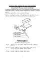
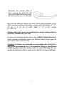
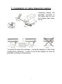
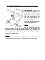
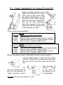
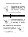
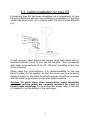
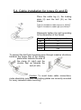
Installation Manual
for KAGO rail contact clamps
and KAGO cable fastening clamps
2
List of contents
1.
Does the clamp fit your rail profile?
4
2.
Installation of rail contact clamps
6
3.
Installation of cable fastening clamps
7
4.
Removal of clamps
8
5.1. Cable installation for types E2 and E3
9
5.2. Cable installation for type E4
10
5.3. Cable installation for type E5
11
5.4. Cable installation for types GI and EI
12
5.5. Cable installation for type EA
13
5.6. Cable laying of railbonds
14
6.1. Why testing of rail contact clamps?
15
6.2. Test instructions before reuse
16
6.3. Groove cleaning and spring checking
17
3
1. Does the clamp fit your rail profile?
Important: Please read carefully!
Hundreds of different rails are in use worldwide! The already developed basic types of KAGO clamps integrate this variety to a large
extent.
The basic types differ in two essential features:
Firstly in length and number of the existing slots, by which it is possible to cover different rail base widths. See example below:
1. slot: 125 mm
2. slot: 140 mm
3. slot: 150 mm
Basic type C
Suitable for the following rails:
- 1st slot:
S49=Form B, S54, SBB I, DSB 45,UIC54E = SBB IV =
Form C.
- 2nd slot: UIC54 = SBB III = 54 kg, 98lb, 109lb, 110A, 113A,
113 lb, U36, U50, EB50T, Ri35G=35GP
- 3rd slot:
UIC60 = SBB VI = UNI60, Ri55, Ri53
4
Secondly the clamps differ in
their opening, by which the different rail base forms are covered. See measure „x“ on the right:
Because the different clamps are often hardly distinguishable at first
sight, we have marked the bottom, namely with the letters „A“, „C“,
„D“, „E“, „I“, „J“, „K”, „N“, „P“, „R81“, „R82“, „T“, „U“, „V” „W“, „Y50N“
or „Y60“ etc.
Always make sure you are mounting the correct clamp which is
perfectly suitable for your rail!
In case of uncertainty please refer to the „KAGO Clamp Directory“
which includes information about the different basic clamp types as
well as the most common rails.
Caution: If clamps are mounted on unsuitable rails, their function is not guaranteed due to incomplete fitting or insufficient
clamping pressure! The worst case is overstretching (for example at switches) which could even result in clamp breakage!
5
2. Installation of rail contact clamps
Caution: Use a hammer with the ideal weight between 1 and 2 kilograms for mounting and removal. It
must not be heavier than 2 kg, otherwise the clamp
or the spring could be damaged.
Place the clamp on the rail base
and give it a few light taps (I) so
that it gets a bit of tension and
starts to grip. Pay attention that
you hit the curve and not the
head of the clamp while hammering!
Afterwards three hard blows will normally do to mount the clamp
sufficiently. After reaching the stop (II), the clamp will automatically
click into place at the rail base‘s lower edge (III). If the clamp jumps
back – which can above all happen with brand-new clamps –, repeat the procedure: At first use light taps, then hit hard. Make sure
the clamp is gripping properly at the front and back!
Don‘t forget: The clamp functions like a spring and therefore has a
tremendous inherent strength. This is necessary, so that the teeth
bite firmly and permanently into the rail, through brake dust, grease,
rust or other residue.
Please wear safety goggles and ensure that nobody is standing in
front of or behind you during the whole mounting procedure!
Duration of installation: KAGO contact clamps are mainly used for
temporary electric connections. However they can also stay built in
permanently for years or even decades without any problem. Even
the most intense clamp vibrations can do no harm, assuming correct installation directions have been followed.
An oxidisation of the contact points is effectively prevented long
term, due to the pressure remaining constant over years.
6
3. Installation of cable fastening clamps
Fastening clamps are
basically mounted in
the same way as contact clamps (see chapter 2)!
To protect the pipe from damage – caused by tamping or other track
maintenance machines –, mount it next to the sleeper as close as
possible, as shown in the pictures.
7
4. Clamp removal of contact and fastening clamps
Contact spring:
For type E4, remove the
spring before detaching the
clamp from the rail! Using
gentle blows on the notches
(fig. I) or the small area at the
top of the contact spring, you
can free it and slide it out.
Please refer chapter 6.2!
For type E2/E3 we recommend the opposite procedure.
Please refer chapter 6.1!
Clamp:
Detach the clamp from the rail
with a well-aimed hammer
blow from above on the tip of the clamp (fig. II). Because the
mounted clamp is under mechanical pressure, it is important that
you ensure nobody is standing behind or in front of you during the
process. Protect yourself by placing the sole of your shoe in the direction of the clamp head.
Caution:
Never strike the side of the clamp (fig. III), because this will impair
its spring pressure and ruin it for further use as a contact clamp!
8
5.1. Cable installation for types E2 and E3
Before mounting the wire or the
cable, first remove the contact
spring. This is done most easily
by gently hammering on the
front end of the contact spring,
before the clamp is mounted to
the rail (ill. left). Otherwise
knock the spring out by wellaimed hits with the pointed end
of the hammer (ill. right).
Some connecting possibilities:
Groove
7 mm
6 mm
10 mm
3 mm
Typ E2
Wire type / Cable cross-section
Wire ø 7 mm
Wire ø 6 mm or flexible
cable 25 mm2 / 35 mm22
2
Flexible cable 50 mm or highly flexible
70 mm
Wire ø 3 mm or flexible cable 4 mm2
Groove
8 mm
5 mm
10 mm
3 mm
Typ E3
Wire type/ Cable cross-section
Wire ø 8 mm or flexible Cable 50 mm22 highly flexible
Wire ø 5 mm or flexible
Cable 16 mm
2
Flexible cable 50 mm or highly flexible
70 mm2
2
Wire ø 3 mm or flexible cable 4 mm
Before use please check if wire/cable fits and in which groove!
Lay the bright cable or wire into the correct
groove (I) and push the contact spring through
the rear slot (II) over the cable into the front
slot.
Now hammer (I)
contact
spring
to the stop (II).
the spring, an exis guaranteed!
the
onto the clamp head up
Due to the pressure of
cellent electrical contact
Caution: Use only one cable at a time!
9
5.2. Cable installation for type E4
Before fixing the cable, the contact spring
must be removed. This is done most easily when the clamp is still mounted on the
rail, namely with gentle taps on the notches (ill. left) or the small area at the top
of the contact spring (in the picture between forefinger and thumb). Simultaneously slide the spring out of the clamp.
Some connecting possibilities:
Groove
5-6 mm
7-10 mm
11-16 mm
17-21 mm
Cable type
Stranded wire
Flexible cable
Flexible cable
Flexible cable
Cross-section
15 mm2
35/50/70 mm2
120 mm2
240 mm2
Afterwards lay the stripped cable into the
correct groove (I) and slide the contact
spring from behind into the clamp head
(II). The cable must be slightly clamped by
the spring pressure, and the contact
spring must hold its position by itself.
Before use please check if cable fits and in which groove!
Now hammer (I) the contact spring
onto the clamp head up to the stop (II).
The notches hold it in position. Due to
the pressure of the spring, an excellent
electrical contact is guaranteed.
Caution: Not appropriate for stiff
cables!
Use only one cable at a time!
10
5.3. Cable installation for type E5
Connecting type E5 has been developed as a complement to type
E4 and is delivered with the loose clamping counterpart (I), the horizontal adjustment part (II), a locking plate (III) and a screw M16x50
(IV).
IV
III
II
I
In both grooves, steel, bronze and copper wires and cables with diameters between 9 and 14 mm can be clamped. This corresponds
with cable cross-sections of ca. 50–120 mm2 according to the conductor structure.
When using big cross-sections, it is recommendable on the one
hand to leave out the washer, so that the screw can be screwed in
deeply enough, on the other hand both grooves should be occupied
with the cable to guarantee an optimal contact pressure.
Caution: To avoid loose cable connections, make absolutely
sure new locking plates are correctly mounted for every renewed cable mounting! For mounting tips please refer to the end
of chapter 5.4. at the bottom of the next page.
11
5.4. Cable installation for types GI and EI
Place the cable lug (I), the locking
plate (II) and the bolt (III) on the
clamp.
Type GI: Suitable for cable lugs up to 150mm22.
Type EI: Suitable for cable lugs up to 240mm .
Afterwards tighten the bolt according
to the dimension of the thread:
Thread
M8
M10
M12
M16
Tightening torque in Nm
15
30
50
120
To prevent the bolt from loosening even through massive vibrations,
hammer the longer flap of the locking
plate down towards the side of
the clamp (ill. right) and the
shorter flap up towards the
bolt (ill. left).
Caution: To avoid loose cable connections,
make absolutely sure that new locking plates are correctly mounted
for every renewed cable mounting!
12
5.5. Cable installation for type EA
Place the cable lug and the re-usable self-locking nut on the clamp.
Then tighten the nut according to the dimension of the stud:
Stud
M8
M10
M12
M16
M20
Tightening torque in Nm
15
30
50
120
240
Type EA: Suitable for cable lugs up to 240 mm2.
Caution: To avoid loose cable connections, please ensure that you
always apply re-usable or new locknuts for every renewed cable
mounting!
13
5.6. Cable laying of railbonds
To protect the cable from damage – caused by tamping or other
track maintenance machines –, lay it as close as possible to rails
and sleepers, as shown in the pictures.
14
6.1. Why testing of rail contact clamps?
KAGO rail contact clamps
were not only developed for
one-way use. On the contrary: If they are always
mounted correctly, KAGO
clamps have a very long lifetime and can be used again
and again! Of course their
clamping pressure could
slightly decrease with every
repeated fastening, so that a
testing of the clamping pressure is recommendable before using KAGO clamps
again! After all they have an
important role to play in railway safety, which means
they must be absolutely dependable!
The testing must be done
with the KAGO testing gauge: If the clamp holds on the
precision pin, the function is
guaranteed (fig. a). If it falls
through, it is no longer usable (fig. b).
When it comes to railbonds,
do not forget to take the opportunity to also check the condition of the cables!
Caution: The existing testing gauge loses its validity for clamps with
the lot marking C26... (see clamp bottom). We look forward to offering you a new testing gauge for C26... clamps!
15
6.2. Testing instructions for KAGO clamps
(1)
Tighten the testing gauge in a vice.
(2)
Place the clamp onto the precision pin of the testing gauge
from above.
(3a) Good: Clamp holds on the pin, i.e. it can be re-used.
(3b) Bad: Clamp falls through, i.e. it is no longer usable.
16
6.3. Groove cleaning and spring checking
(only for connecting types E2, E3 & E4)
Low voltage connections (1,5-12 Volt)
are only guaranteed
as long as each
KAGO clamp is
tested after use with
the gauge and if
dirty grooves have
been cleaned by
means of a steel
brush and a liquid
cleaner (like paraffin) if required!
E2
E3
Contact springs can
break
when
mounted carelessly
(too hard hits, canting, etc.)! They must
be treated – unlike
the clamp itself – as
wearing parts that
have to be replaced
when signs of wear
and tear like deformations, cracks, etc.
appear!
E4
17
18
19
The policy of KAGO AG is one of continuous development. The
company therefore reserves the right to change specifications and
introduce design improvements at any time and without notice.
For more detailled information please refer to our „KAGO Clamp
Directory“!
This installation manual must be strictly obeyed and no KAGO
clamps must be modified mechanically or by welding,
otherwise any product liability will be rejected.
The latest update of this booklet can be found on
http://www.kago.com/pdf/e_62_mi.pdf
Copyright by KAGO AG.
All rights reserved.
Version 19.11.2012
20