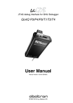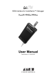
1
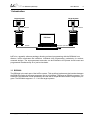
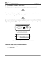
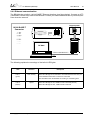
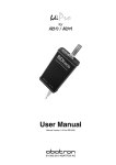
bdi Pro
for
MIPS32
Installation Manual
Manual Version 1.01 for BDI3000
©1993-2011 by Abatron AG
bdiPro
for BDI3000 (MIPS32)
User Manual
2
1 Introduction ................................................................................................................................. 3
1.1 BDI3000................................................................................................................................. 3
1.2 Functions ............................................................................................................................... 4
2 Installation ................................................................................................................................... 5
2.1 Connecting the BDI3000 to Target ........................................................................................ 5
2.2 Connecting the BDI3000 to Power Supply ............................................................................ 7
2.3 Status LED «MODE»............................................................................................................. 8
2.4 Connecting the BDI3000 to Host ........................................................................................... 9
2.4.1 Serial line communication ............................................................................................ 9
2.4.2 Ethernet communication ............................................................................................ 10
2.5 Installation of the bdiPro Software....................................................................................... 11
2.6 Configuration ....................................................................................................................... 11
2.6.1 BDI3000 Setup/Update .............................................................................................. 12
3 Specifications ............................................................................................................................ 14
4 Environmental notice................................................................................................................ 15
5 Declaration of Conformity (CE)................................................................................................ 15
6 Abatron Warranty and Support Terms .................................................................................... 16
6.1 Hardware ............................................................................................................................. 16
6.2 Software .............................................................................................................................. 16
6.3 Warranty and Disclaimer ..................................................................................................... 16
6.4 Limitation of Liability ............................................................................................................ 16
Appendices
A Troubleshooting ....................................................................................................................... 17
B Maintenance .............................................................................................................................. 17
C Trademarks ............................................................................................................................... 17
© Copyright 1993-2011 by ABATRON AG
V
1.01
bdiPro
for BDI3000 (MIPS32)
User Manual
3
1 Introduction
Target System
Target System
MIPS
MIPS
JTAG Interface
JTAG Interface
BDI3000
BDI3000
PC Host
Abatron AGSwiss Made
Abatron AGSwiss Made
RS232
Ethernet (10/100 BASE-T)
bdiPro is a powerful software package, allowing on-board programming with the BDI3000 from
Abatron. bdiPro eliminates the inefficient, individual chip programming, particularly for surfacemounted designs. The unprogrammed memories can be soldered to the printed circuit board and
programmed simultaneously on a just-in-time basis.
1.1 BDI3000
The BDI3000 is the main part of the bdiPro system. This small box implements the interface between
the BDM/JTAG pins of the target processor and a 10/100Base-T Ethernet or RS232 connector. The
firmware of the BDI3000 can be updated by the user with a simple Windows based configuration program. The BDI3000 supports 1.2 – 5.0 Volts target systems.
© Copyright 1993-2011 by ABATRON AG
V
1.01
bdiPro
for BDI3000 (MIPS32)
User Manual
4
1.2 Functions
The bdiPro software provides the following functions:
File
Edit
Target
Setup
Load/Save
• Save and recall user defined program sets
Print
• Print the active program set
Print Preview
• Display the active program set on the screen
Print Setup
• Select the printer and the printer connection
Print Comment
• Edit the headers and comment
Load
• Load the program file (Binary, Motorola S-Record and Intel hex)
Store
• Store the local memory image in S-Record format
Dump
• Load the target system data into local memory
Edit
• Edit the local memory image
Clear
• Clear the local memory image
Fill
• Fill a local memory area with pattern
Checksum
• Calculation of checksum
Erase
• Erase the target memory (all / sectors)
Program
• Program the target memory
Verify
• Compare the target system memory with local memory
Communication
• Communication setup between the PC and the BDI
Firmware
• Load and verify the firmware
Target Memory
• Target memory setup (memory type and memory organisation)
Target Initlists
• User configurable program sequences for target system initialization
(clock, chip select...)
• If required, you can write special routines that runs before or after
the program/erase process (pre-programming, post-programming /
pre-erase, post-erase).
Help
• Information about menus and dialog boxes by pressing the F1
function key
© Copyright 1993-2011 by ABATRON AG
V
1.01
bdiPro
for BDI3000 (MIPS32)
User Manual
5
2 Installation
2.1 Connecting the BDI3000 to Target
The cables to the target system are designed for the IDT RC32300 Development Boards (optional
available: Part# 90070) and for EJTAG 2.5 compatible boards (enclosed). In case where the target
system has the same connector layout, the cable (14 pin or 24 pin) can be directly connected.
!
In order to ensure reliable operation of the BDI (EMC, runtimes, etc.) the target cable length must not
exceed 25 cm (10").
1
23
Target System
MIPS
1
2
13
optional
available
24
(P/N 90070)
2 Key
14 pin EJTAG
Connector
14
TRGT
MODE
BDI
BDI3000
BDI
9
TARGET A
10
TARGET B
1
2
The green LED «TRGT» marked light up when target is powered up
1 - TRST
2 - NC
3 - TDI
4 - NC
5 - TDO
6 - GROUND
7 - TMS
8 - GROUND
9 - TCK
10 - NC
11 - RESET
12 - key
13 - DINT
14 - VIO Target
24 pin RC32300
Connector
1 - TRST
2 - GROUND
3 - TDI
4 - GROUND
5 - TDO
6 - GROUND
7 - TMS
8 - GROUND
9 - TCK
10 - GROUND
11 - RESET
12 - GROUND
13 - NC
14 - GROUND
15 - NC
16 - GROUND
17 - NC
18 - GROUND
19 - NC
20 - GROUND
21 - DBGBOOT
22 - GROUND
23 - VIO Target
24 - GROUND
20 - NC
For BDI TARGET A connector signals see table on next page.
Warning:
Before you can use the BDI3000 with an other target processor type (e.g. MIPS <--> ARM), a new
setup has to be done (see chapter 2.5). During this process the target cable must be disconnected
from the target system.
!
To avoid data line conflicts, the BDI3000 must be disconnected from the target system while
programming a new firmware for an other target CPU.
© Copyright 1993-2011 by ABATRON AG
V
1.01
bdiPro
for BDI3000 (MIPS32)
User Manual
6
BDI MAIN / TARGET A Connector Signals
Pin
Name
Describtion
1
DINT
EJTAG Debug Interrupt
EJTAG 2.5: This output of the BDI3000 connects to the target DINT line.
RC32300: This output of the BDI3000 connects to the target DebugBoot line.
2
TRST
EJTAG Test Reset
This output of the BDI3000 resets the JTAG TAP controller on the target.
3+5
GND
System Ground
4
TCK
EJTAG Test Clock
This output of the BDI3000 connects to the target TCK line.
6
TMS
EJTAG Test Mode Select
This output of the BDI3000 connects to the target TMS line.
7
RESET
This open collector output of the BDI3000 is used to reset the target system.
8
TDI
EJTAG Test Data In
This output of the BDI3000 connects to the target TDI line.
9
VIO Target
1.2 – 5.0V:
This is the target reference voltage. It indicates that the target has power and it is also used
to create the logic-level reference for the input comparators. It also controls the output logic
levels to the target. It is normally fed from Vdd I/O on the target board.
10
TDO
EJTAG Test Data Out
This input to the BDI3000 connects to the target TDO line.
© Copyright 1993-2011 by ABATRON AG
V
1.01
bdiPro
for BDI3000 (MIPS32)
User Manual
7
2.2 Connecting the BDI3000 to Power Supply
The BDI3000 needs to be supplied with the enclosed power supply from Abatron (5VDC).
!
Before use, check if the mains voltage is in accordance with the input voltage printed on power
supply. Make sure that, while operating, the power supply is not covered up and not situated near
a heater or in direct sun light. Dry location use only.
!
For error-free operation, the power supply to the BDI3000 must be between 4.75V and 5.25V DC.
The maximal tolerable supply voltage is 5.25 VDC. Any higher voltage or a wrong polarity
might destroy the electronics.
+5 VDC
RS232
GND
POWER
TRGT
MODE
BDI
casing connected to ground terminal
TARGET A
TARGET B
The green LED «BDI» marked light up when 5V power is connected to the BDI3000
Please switch on the system in the following sequence:
• 1 –> external power supply
• 2 –> target system
© Copyright 1993-2011 by ABATRON AG
V
1.01
bdiPro
for BDI3000 (MIPS32)
User Manual
8
2.3 Status LED «MODE»
MODE
TRGT
BDI
The built in LED indicates the following BDI states:
MODE LED
TARGET A
TARGET B
BDI STATES
OFF
The BDI is ready for use, the firmware is already loaded.
ON
The output voltage from the power supply is too low.
BLINK
The BDI «loader mode» is active (an invalid firmware is loaded or loading firmware is active).
© Copyright 1993-2011 by ABATRON AG
V
1.01
bdiPro
for BDI3000 (MIPS32)
User Manual
9
2.4 Connecting the BDI3000 to Host
2.4.1 Serial line communication
The host is connected to the BDI through the serial interface (COM1...COM4). The communication
cable (included) between BDI and Host is a serial cable. There is the same connector pinout for the
BDI and for the Host side (Refer to Figure below).
Target System
RS232 Connector
(for PC host)
12345
MIPS
1 - NC
2 - RXD data from host
3 - TXD data to host
4 - NC
5 - GROUND
6 - NC
7 - NC
8 - NC
9 - NC
6789
RS232
POWER
BDI3000
PC Host
RS232
© Copyright 1993-2011 by ABATRON AG
V
1.01
bdiPro
for BDI3000 (MIPS32)
User Manual
10
2.4.2 Ethernet communication
The BDI3000 has a built-in 10/100 BASE-T Ethernet interface (see figure below). Connect an UTP
(Unshielded Twisted Pair) cable to the BD3000. Contact your network administrator if you have questions about the network.
Target System
10/100 BASE-T
Connector
1
8
MIPS
1 - TD+
2 - TD3 - RD+
4 - NC
5 - NC
6 - RD7 - NC
8 - NC
RS232
POWER
LED1
LED2
BDI3000
PC Host
Ethernet (10/100 BASE-T)
The following explains the meanings of the built-in LED lights:
LED
Function
Description
LED 1
(green)
Link / Activity
When this LED light is ON, data link is successful between the UTP port
of the BDI3000 and the hub to which it is connected.
The LED blinks when the BDI3000 is receiving or transmitting data.
LED 2
(amber)
Speed
© Copyright 1993-2011 by ABATRON AG
When this LED light is ON, 100Mb/s mode is selected (default).
When this LED light is OFF, 10Mb/s mode is selected
V
1.01
bdiPro
for BDI3000 (MIPS32)
User Manual
11
2.5 Installation of the bdiPro Software
On the enclosed CD you will find the bdiPro software and the firmware required for the BDI. Copy all
the files to a directory on your harddisk.
The following files are on the CD:
b30pgr4k.exe
bdiPro program
b30pgr4k.chm
Helpfile for bdiPro program
b30r4kfw.xxx
Firmware for BDI3000 for MIPS32 targets
bdiifc32.dll
BDI Interface DLL
xxxxxx.pro
Predefined Program sets
Installing BDI Pro:
• Create a new directory on your harddisk, for example C:\BDIPRO.
• Copy the entire contents of the enclosed CD into this directory.
2.6 Configuration
Before you can use the full functionality of the bdiPro software, you must configure the system
correctly. The Setup Menu enables you to perform the following configuration tasks:
• Set the correct communication parameters
between the PC and the BDI.
--> Communication
• Load or update the firmware / logic
--> Firmware
• Configure the target system: memory type
and memory organization
--> Target Memory
• Program the initialization routines for the
target system.
--> Target Initlists
Any time you need information about specific menus and dialog boxes, you can display the integrated
Help screens by pressing the F1 function key.
The Edit and Target menus will only become active when you have specified a memory type (see
Target Memory in the Setup Menu).
© Copyright 1993-2011 by ABATRON AG
V
1.01
bdiPro
for BDI3000 (MIPS32)
User Manual
12
2.6.1 BDI3000 Setup/Update
First make sure that the BDI is properly connected (see Chapter 2.1 to 2.4). The BDI must be connected via RS232 to the Windows host.
!
To avoid data line conflicts, the BDI3000 must be disconnected from the target system while
programming the firmware for an other target CPU family.
The following dialogbox is used to check or update the BDI firmware and to set the network parameters.
dialog box «BDI3000 Update/Setup»
The following options allow you to update the BDI3000 firmware and store the network parameters:
Port
Select the communication port where the BDI3000 is connected during
this setup session.
Speed
Select the baudrate used to communicate with the BDI3000 loader during
this setup session.
Connect
Click on this button to establish a connection with the BDI3000 loader.
Once connected, the BDI3000 remains in loader mode until it is restarted
or this dialog box is closed.
Current
Press this button to read back the current loaded BDI3000 firmware version. The current firmware version will be displayed.
Erase
Press this button to erase the current loaded firmware.
© Copyright 1993-2011 by ABATRON AG
V
1.01
bdiPro
for BDI3000 (MIPS32)
User Manual
13
Update
This button is only active if there is a newer firmware version present in the
execution directory of the setup software. Press this button to write the
new firmware into the BDI3000 flash memory.
BDI IP Address
Enter the IP address for the BDI3000. Use the following format:
xxx.xxx.xxx.xxx e.g.151.120.25.101
Ask your network administrator for assigning an IP address to this
BDI3000. Every BDI3000 in your network needs a different IP address.
Subnet Mask
Enter the subnet mask of the network where the BDI is connected to.
Use the following format: xxx.xxx.xxx.xxxe.g.255.255.255.0
A subnet mask of 255.255.255.255 disables the gateway feature.
Ask your network administrator for the correct subnet mask.
Default Gateway
Enter the IP address of the default gateway. Ask your network administrator for the correct gateway IP address. If the gateway feature is disabled,
you may enter 255.255.255.255 or any other value.
Transmit
Click on this button to store the configuration in the BDI3000 flash
memory.
Default IP: 192.168.53.72
Before the BDI is configured the first time, it has a default IP of 192.168.53.72 that allows an initial
configuration via Ethernet. If your host is not able to connect to this default IP, then the initial configuration has to be done via the serial connection.
Note:
If there is currently a firmware loaded, setup via the Network channel is only possible if the BDI3000
is already in Loader mode (Mode LED blinking). To force Loader mode, enter "boot loader" at the
Telnet. The setup tool tries first to establish a connection to the Loader via the IP address present in
the "BDI IP Address" entry field. If there is no connection established after a time-out, it tries to connect to the default IP (192.168.53.72).
© Copyright 1993-2011 by ABATRON AG
V
1.01
bdiPro
for BDI3000 (MIPS32)
User Manual
14
3 Specifications
Operating Voltage Limiting
5 VDC ± 0.25 V
Power Supply Current
typ. 500 mA
max. 1000 mA
RS232 Interface: Baud Rates
Data Bits
Parity Bits
Stop Bits
9’600,19’200, 38’400, 57’600,115’200
8
none
1
Network Interface
10/100 BASE-T
BDM/JTAG clock
up to 32 MHz
Supported target voltage
1.2 – 5.0 V
Operating Temperature
+ 5 °C ... +60 °C
Storage Temperature
-20 °C ... +65 °C
Relative Humidity (noncondensing)
<90 %rF
Size
160 x 85 x 35 mm
Weight (without cables)
280 g
Host Cable length (RS232)
2.5 m
Electromagnetic Compatibility
CE compliant
Restriction of Hazardous Substances
RoHS 2002/95/EC compliant
Specifications subject to change without notice
© Copyright 1993-2011 by ABATRON AG
V
1.01
bdiPro
for BDI3000 (MIPS32)
User Manual
15
4 Environmental notice
Disposal of the equipment must be carried out at a designated disposal site.
5 Declaration of Conformity (CE)
© Copyright 1993-2011 by ABATRON AG
V
1.01
bdiPro
for BDI3000 (MIPS32)
User Manual
16
6 Abatron Warranty and Support Terms
6.1 Hardware
ABATRON Switzerland warrants that the Hardware shall be free from defects in material and workmanship for a period of 3 years following the date of purchase when used under normal conditions.
Failure in handling which leads to defects or any self-made repair attempts are not covered under
this warranty. In the event of notification within the warranty period of defects in material or workmanship, ABATRON will repair or replace the defective hardware. The customer must contact the distributor or Abatron for a RMA number prior to returning.
6.2 Software
License
Against payment of a license fee the client receives a usage license for this software product, which
is not exclusive and cannot be transferred.
Copies
The client is entitled to make copies according to the number of licenses purchased. Copies
exceeding this number are allowed for storage purposes as a replacement for defective storage
mediums.
Update and Support
The agreement includes free software maintenance (update and support) for one year from date of
purchase. After this period the client may purchase software maintenance for an additional year.
6.3 Warranty and Disclaimer
ABATRON AND ITS SUPPLIERS HEREBY DISCLAIMS AND EXCLUDES, TO THE EXTENT
PERMITTED BY APPLICABLE LAW, ALL WARRANTIES, EXPRESS OR IMPLIED, INCLUDING
WITHOUT LIMITATION, ANY WARRANTIES OF MERCHANTABILITY, FITNESS FOR A
PARTICULAR PURPOSE, TITLE AND NON-INFRINGEMENT.
6.4 Limitation of Liability
IN NO EVENT SHALL ABATRON OR ITS SUPPLIERS BE LIABLE TO YOU FOR ANY DAMAGES,
INCLUDING, WITHOUT LIMITATION, ANY SPECIAL, INDIRECT, INCIDENTAL OR
CONSEQUENTIAL DAMAGES, ARISING OUT OF OR IN CONNECTION WITH THE USE OR
PERFORMANCE OF THE HARDWARE AND/OR SOFTWARE, INCLUDING WITHOUT
LIMITATION, LOSS OF PROFITS, BUSINESS, DATA, GOODWILL, OR ANTICIPATED SAVINGS,
EVEN IF ADVISED OF THE POSSIBILITY OF THOSE DAMAGES.
The hardware and software product with all its parts, copyrights and any other rights remain in possession of ABATRON. Any dispute, which may arise in connection with the present agreement shall
be submitted to Swiss Law in the Court of Zug (Switzerland) to which both parties hereby assign competence.
© Copyright 1993-2011 by ABATRON AG
V
1.01
bdiPro
for BDI3000 (MIPS32)
User Manual
17
Appendices
A Troubleshooting
Problem
The firmware can not be loaded.
Possible reasons
• The BDI is not correctly connected with the Host (see chapter 2).
• A wrong communication port is selected (Com 1...Com 4).
• The BDI is not powered up
Problem
No working with the target system (loading firmware is okay).
Possible reasons
• Wrong pin assignment (BDM/JTAG connector) of the target system (see chapter 2).
• Target system initialization is not correctly –> enter an appropriate target initialization list.
• An incorrect IP address was entered (BDI3000 configuration)
• BDM/JTAG signals from the target system are not correctly (short-circuit, break, ...).
• The target system is damaged.
Problem
Network processes do not function (loading the firmware was successful)
Possible reasons
• The BDI3000 is not connected or not correctly connected to the network (LAN cable or media
converter)
• An incorrect IP address was entered (BDI3000 configuration)
B Maintenance
The BDI needs no special maintenance. Clean the housing with a mild detergent only. Solvents such
as gasoline may damage it.
C Trademarks
All trademarks are property of their respective holders.
© Copyright 1993-2011 by ABATRON AG
V
1.01