1
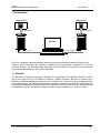
bdi Pro
for
ARM7 / ARM9
User Manual
Manual Version 1.02 for BDI1000
© 1993-2010 ABATRON AG
bdiPro for BDI1000 (ARM7/9/9E)
User Manual
2
1 Introduction ................................................................................................................................. 3
1.1 BDI1000................................................................................................................................. 3
1.2 Functions ............................................................................................................................... 4
2 Installation ................................................................................................................................... 5
2.1 Connecting the BDI1000 to Target ........................................................................................ 5
2.1.1 Changing Target Processor Type ................................................................................ 7
2.2 Connecting the BDI1000 to Power Supply ............................................................................ 8
2.2.1 External Power Supply................................................................................................. 8
2.2.2 Power Supply from Target System .............................................................................. 9
2.3 Status LED «MODE»........................................................................................................... 10
2.4 Connecting the BDI1000 to Host ......................................................................................... 11
2.4.1 Serial line communication .......................................................................................... 11
2.4.2 Ethernet communication ............................................................................................ 12
2.5 Installation of the bdiPro Software....................................................................................... 13
2.6 Configuration ....................................................................................................................... 13
2.6.1 BDI1000 Setup/Update .............................................................................................. 14
2.6.2 Recover procedure..................................................................................................... 15
3 Specifications ............................................................................................................................ 16
4 Environmental notice................................................................................................................ 17
5 Declaration of Conformity (CE)................................................................................................ 17
6 Warranty..................................................................................................................................... 18
Appendices
A Troubleshooting ....................................................................................................................... 19
B Maintenance .............................................................................................................................. 20
C Trademarks ............................................................................................................................... 22
© Copyright 1993-2010 by ABATRON AG
V
1.02
bdiPro for BDI1000 (ARM7/9/9E)
User Manual
3
1 Introduction
Target System
Target System
ARM
ARM
JTAG Interface
JTAG Interface
BDI1000
BDI1000
PC Host
RS232
Ethernet (10 BASE-T)
bdiPro is a powerful software package, allowing on-board programming with the BDI1000 from
Abatron. bdiPro eliminates the inefficient, individual chip programming, particularly for surfacemounted designs. The unprogrammed memories can be soldered to the printed circuit board and
programmed simultaneously on a just-in-time basis.
1.1 BDI1000
The BDI1000 is a processor system in a small box. It implements the interface between the JTAG
pins of the target CPU and a 10Base-T Ethernet / RS232 connector. BDI1000 is powered by a
MC68331, 256Kbyte RAM and a flash memory of 512Kbyte. As a result of consistent implementation
of lasted technology, the BDI1000 is optimally prepared for further enhancements. The firmware and
the programmable logic of the BDI1000 can be updated by the user with a simple Windows based
configuration program. The BDI1000 supports target system voltages from 1.8 up to 5 Volts.
© Copyright 1993-2010 by ABATRON AG
V
1.02
bdiPro for BDI1000 (ARM7/9/9E)
User Manual
4
1.2 Functions
The bdiPro software provides the following functions:
File
Edit
Target
Setup
Load/Save
• Save and recall user defined program sets
Print
• Print the active program set
Print Preview
• Display the active program set on the screen
Print Setup
• Select the printer and the printer connection
Print Comment
• Edit the headers and comment
Load
• Load Motorola S-Record and Intel hex program files
Store
• Store the local memory image in S-Record format
Dump
• Load the target system data into local memory
Edit
• Edit the local memory image
Clear
• Clear the local memory image
Fill
• Fill a local memory area with pattern
Checksum
• Calculation of checksum
Erase
• Erase the target memory (all / sectors)
Program
• Program the target memory
Verify
• Compare the target system memory with local memory
Communication
• Communication setup between the PC and the BDI
Firmware
• Load and verify the firmware
Target Memory
• Target memory setup (memory type and memory organisation)
Target Initlists
• User configurable program sequences for target system initialization
(clock, chip select...)
• If required, you can write special routines that runs before or after
the program/erase process (pre-programming, post-programming /
pre-erase, post-erase).
Help
• Information about menus and dialog boxes by pressing the F1
function key
© Copyright 1993-2010 by ABATRON AG
V
1.02
bdiPro for BDI1000 (ARM7/9/9E)
User Manual
5
2 Installation
2.1 Connecting the BDI1000 to Target
The enclosed cables to the target system are designed for the ARM Development Boards. In case
where the target system has the same connector layout, the cable (14 pin or 20 pin) can be directly
connected.
!
In order to ensure reliable operation of the BDI (EMC, runtimes, etc.) the target cable length must not
exceed 20 cm (8").
1
19
Target System
1
ARM
2
13
20
14 pin Target
Connector
14
2
MODE
TRGT
BDI
BDI1000
BDI
9
TARGET A
10
1
TARGET B
2
The green LED «TRGT» marked light up when target is powered up
1 - Vcc Target
2 - GROUND
3 - TRST
4 - GROUND
5 - TDI
6 - NC
7 - TMS
8 - NC
9 - TCK
10 - NC
11 - TDO
12 - RESET
13 - NC
14 - NC
20 pin Multi-ICE
Connector
1 - Vcc Target
2 - NC
3 - TRST
4 - NC
5 - TDI
6 - NC
7 - TMS
8 - GROUND
9 - TCK
10 - GROUND
11 - NC
12 - NC
13 - TDO
14 - NC
15 - RESET
16 - NC
17 - NC
18 - NC
19 - NC
20 - NC
TARGET A connector signals see table on next page.
© Copyright 1993-2010 by ABATRON AG
V
1.02
bdiPro for BDI1000 (ARM7/9/9E)
User Manual
6
TARGET A Connector Signals
Pin
Name
Describtion
1
reserved
This pin is currently not used.
2
TRST
JTAG Test Reset
This open-drain / push-pull output of the BDI1000 resets the JTAG TAP controller on the
target. Default driver type is open-drain. With a special init list entry it can be changed to
push-pull (see online help).
3+5
GND
System Ground
4
TCK
JTAG Test Clock
This output of the BDI1000 connects to the target TCK line.
6
TMS
JTAG Test Mode Select
This output of the BDI1000 connects to the target TMS line.
7
RESET
This open collector output of the BDI1000 is used to reset the target system.
8
TDI
JTAG Test Data In
This output of the BDI1000 connects to the target TDI line.
9
Vcc Target
This input to the BDI1000 is used to detect if the target is powered up.
10
TDO
JTAG Test Data Out
This input to the BDI1000 connects to the target TDO line.
The BDI1000 works also with targets which have no dedicated TRST pin. For this kind of targets, the
BDI cannot force the target to debug mode immediately after reset. The target always begins execution of application code until the BDI has finished programming the Debug Control Register.
© Copyright 1993-2010 by ABATRON AG
V
1.02
bdiPro for BDI1000 (ARM7/9/9E)
User Manual
7
2.1.1 Changing Target Processor Type
Before you can use the BDI1000 with an other target processor type (e.g. ARM <--> PPC), a new
setup has to be done (see chapter 2.6 «Configuration»). During this process the target cable must
be disconnected from the target system. The BDI1000 needs to be supplied between 2.5V and 5V
via the POWER connector. For more information see chapter 2.2.1 «External Power Supply».
!
To avoid data line conflicts, the BDI1000 must be disconnected from the target system while
programming the logic for an other target CPU.
© Copyright 1993-2010 by ABATRON AG
V
1.02
bdiPro for BDI1000 (ARM7/9/9E)
User Manual
8
2.2 Connecting the BDI1000 to Power Supply
2.2.1 External Power Supply
The BDI1000 needs to be supplied between 2.5V and 5V via the POWER connector. The available
power supply from Abatron (option) or the enclosed power cable can be directly connected. In order
to ensure reliable operation of the BDI1000, keep the power supply cable as short as possible.
!
For error-free operation, the power supply to the BDI1000 must be between 2.5V and 5V DC. The
maximal tolerable supply voltage is 5.25 VDC. Any higher voltage or a wrong polarity might
destroy the electronics.
GND 3
MODE
TRGT
BDI
RS232
LI
TARGET A
4
1 Vcc
POWER
2
POWER Connector
1 - Vcc (+2.5 ... +5V)
2 - VccTGT
3 - GROUND
4 - NOT USED
10 BASE-T
TARGET B
The green LED «BDI» marked light up when power (2.5 – 5V) is connected to the BDI1000
Please switch on the system in the following sequence:
• 1 --> external power supply
• 2 --> target system
© Copyright 1993-2010 by ABATRON AG
V
1.02
bdiPro for BDI1000 (ARM7/9/9E)
User Manual
9
2.2.2 Power Supply from Target System
The BDI1000 needs to be supplied between 2.5V and 5V via TARGET A connector. This mode can
only be used when the target system runs between 2.5V and 5V and the pin «Vcc Target» is able to
deliver a current up to:
• [email protected] Target
• [email protected] Target
• [email protected] Target
For pin description and layout see chapter 2.1 «Connecting the BDI1000 to Target». Insert the enclosed Jumper as shown in figure below. Please ensure that the jumper is inserted correctly.
!
For error-free operation, the power supply to the BDI1000 must be between 2.5V and 5V DC. The
maximal tolerable supply voltage is 5.25 VDC. Any higher voltage or a wrong polarity might
destroy the electronics.
Jumper
POWER Connetcor
3
4
RS232
LI
1 - Vcc BDI1000 (+2.5 ... +5V)
2 - Vcc Target (+2.5 ... +5V)
3 - GROUND
4 - NOT USED
1
2
POWER
10 BASE-T
TRGT
MODE
BDI
Target A Connector
TARGET A
9
TARGET B
5 3
The green LEDs «BDI» and «TRGT» marked light up when target is powered up
and the jumper is inserted correctly
© Copyright 1993-2010 by ABATRON AG
1 - Reserved
2 - TRST
3 - GROUND
4 - TCK
5 - GROUND
6 - TMS
7 - RESET
8 - TDI
9 - Vcc Target
10 - TDO
V
1.02
bdiPro for BDI1000 (ARM7/9/9E)
User Manual
10
2.3 Status LED «MODE»
TRGT
MODE
BDI
The built in LED indicates the following BDI states:
MODE LED
TARGET A
TARGET B
BDI STATES
OFF
The BDI is ready for use, the firmware is already loaded.
ON
The power supply for the BDI1000 is < 2.5VDC.
BLINK
The BDI «loader mode» is active (an invalid firmware is loaded or loading firmware is active).
© Copyright 1993-2010 by ABATRON AG
V
1.02
bdiPro for BDI1000 (ARM7/9/9E)
User Manual
11
2.4 Connecting the BDI1000 to Host
2.4.1 Serial line communication
The host is connected to the BDI through the serial interface (COM1...COM4). The communication
cable between BDI and Host is a serial cable (RXD / TXD are crossed). There is the same connector
pinout for the BDI and for the Host side (Refer to Figure below).
Target System
RS232 Connector
(for PC host)
1 - NC
2 - RXD data from host
3 - TXD data to host
4 - NC
5 - GROUND
6 - NC
7 - NC
8 - NC
9 - NC
12345
ARM
6789
RS232
LI
POWER
10 BASE-T
BDI1000
PC Host
RS232
© Copyright 1993-2010 by ABATRON AG
V
1.02
bdiPro for BDI1000 (ARM7/9/9E)
User Manual
12
2.4.2 Ethernet communication
The BDI1000 has a built-in 10 BASE-T Ethernet interface (see figure below). Connect an UTP (Unshilded Twisted Pair) cable to the BD1000. For thin Ethernet coaxial networks you can connect a
commercially available media converter (BNC --> 10 BASE-T) between your network and the
BDI1000. Contact your network administrator if you have questions about the network.
10 BASE-T
Connector
1 - TD+
2 - TD3 - RD+
4 - NC
5 - NC
6 - RD7 - NC
8 - NC
1
8
Target System
ARM
RS232
LI
POWER
10 BASE-T
When the LI LED light is ON, data link is successful between the
UTP port of the BDI1000 and the hub to which it is connected.
BDI1000
PC Host
Ethernet (10 BASE-T)
© Copyright 1993-2010 by ABATRON AG
V
1.02
bdiPro for BDI1000 (ARM7/9/9E)
User Manual
13
2.5 Installation of the bdiPro Software
On the enclosed CD you will find the bdiPro software and the firmware required for the BDI. Copy all
the files from the CD to a directory on your hard disk.
The following files are on the CD (zipped):
b10pgarm.exe
bdiPro program
b10pgarm.chm
Helpfile for bdiPro program
b10armfw.xxx
Firmware for BDI1000 for ARM7/9TDMI targets
armjed10.xxx
JEDEC file for the BDI logic device programming
bdiifc32.dll
BDI Interface DLL
xxxxxx.pro
Predefined Program sets
Installing BDI Pro:
• Create a new directory on your hard disk, for example C:\BDIPRO.
• Copy the entire contents of the enclosed CD into this directory.
2.6 Configuration
Before you can use the full functionality of the bdiPro software, you must configure the system
correctly. The Setup Menu enables you to perform the following configuration tasks:
• Set the correct communication parameters
between the PC and the BDI.
--> Communication
• Load or update the firmware / logic
--> Firmware
• Configure the target system: memory type
and memory organization
--> Target Memory
• Program the initialization routines for the
target system.
--> Target Initlists
Any time you need information about specific menus and dialog boxes, you can display the integrated
Help screens by pressing the F1 function key.
The Edit and Target menus will only become active when you have specified a memory type (see
Target Memory in the Setup Menu).
© Copyright 1993-2010 by ABATRON AG
V
1.02
bdiPro for BDI1000 (ARM7/9/9E)
User Manual
14
2.6.1 BDI1000 Setup/Update
First make sure that the BDI is properly connected (see Chapter 2.1 to 2.4). The BDI must be connected via RS232 to the Windows host.
!
To avoid data line conflicts, the BDI1000 must be disconnected from the target system while
programming the logic for an other target CPU (see Chapter 2.1.1).
The following dialogbox is used to check or update the BDI firmware and logic and to set the network
parameters.
dialog box «BDI1000 Update/Setup»
The following options allow you to update the BDI1000 firmware and store the network parameters:
Port
Select the communication port where the BDI1000 is connected during
this setup session.
Speed
Select the baudrate used to communicate with the BDI1000 loader during
this setup session.
Connect
Click on this button to establish a connection with the BDI1000 loader.
Once connected, the BDI1000 remains in loader mode until it is restarted
or this dialog box is closed.
Current
Press this button to read back the current loaded BDI1000 firmware version. The current firmware version will be displayed.
Erase
Press this button to erase the current loaded firmware.
Update
This button is only active if there is a newer firmware version present in the
execution directory of the setup software. Press this button to write the
new firmware into the BDI1000 flash memory.
© Copyright 1993-2010 by ABATRON AG
V
1.02
bdiPro for BDI1000 (ARM7/9/9E)
User Manual
15
BDI IP Address
Enter the IP address for the BDI1000. Use the following format:
xxx.xxx.xxx.xxx e.g.151.120.25.101
Ask your network administrator for assigning an IP address to this
BDI1000. Every BDI1000 in your network needs a different IP address.
Subnet Mask
Enter the subnet mask of the network where the BDI is connected to.
Use the following format: xxx.xxx.xxx.xxxe.g.255.255.255.0
A subnet mask of 255.255.255.255 disables the gateway feature.
Ask your network administrator for the correct subnet mask.
Default Gateway
Enter the IP address of the default gateway. Ask your network administrator for the correct gateway IP address. If the gateway feature is disabled,
you may enter 255.255.255.255 or any other value.
Transmit
Click on this button to store the configuration in the BDI1000 flash
memory.
2.6.2 Recover procedure
In rare instances you may not be able to load the firmware in spite of a correctly connected BDI (error
of the previous firmware in the flash memory). Before carrying out the following procedure, check
the possibilities in Appendix «Troubleshooting». In case you do not have any success with the
tips there, do the following:
• Switch OFF the power supply for the BDI and open the unit as
described in Appendix «Maintenance»
• Place the jumper in the «INIT MODE» position
• Connect the power cable or target cable if the BDI is powered
from target system
Jumper
• Switch ON the power supply for the BDI again and wait until the
LED «MODE» blinks fast
INIT MODE
• Turn the power supply OFF again
DEFAULT
• Return the jumper to the «DEFAULT» position
• Reassemble the unit as described in Appendix «Maintenance»
© Copyright 1993-2010 by ABATRON AG
V
1.02
bdiPro for BDI1000 (ARM7/9/9E)
User Manual
16
3 Specifications
Operating Voltage Limiting
2.5 ... 5.25VDC
Power Supply Current (max)
[email protected]
[email protected]
[email protected]
RS232 Interface: Baud Rates
Data Bits
Parity Bits
Stop Bits
9’600,19’200, 38’400, 57’600,115’200
8
none
1
Network Interface
10 BASE-T
Serial Transfer Rate between BDI and Target
5.5 Mbit/s (BDM)
12 Mbit/s (JTAG)
Supported target voltage
1.8 ... 5 VDC
Operating Temperature
+ 5 °C ... +60 °C
Storage Temperature
-20 °C ... +65 °C
Relative Humidity (noncondensing)
<90 %rF
Size
160 x 85 x 35 mm
Weight (without cables)
280 g
Electromagnetic Compatibility (EMC)
EN 50081-2, EN 50082-2
Specifications subject to change without notice
© Copyright 1993-2010 by ABATRON AG
V
1.02
bdiPro for BDI1000 (ARM7/9/9E)
User Manual
17
4 Environmental notice
Disposal of the equipment must be carried out at a designated disposal site.
5 Declaration of Conformity (CE)
© Copyright 1993-2010 by ABATRON AG
V
1.02
bdiPro for BDI1000 (ARM7/9/9E)
User Manual
18
6 Warranty
ABATRON Switzerland warrants the physical CD, cable, BDI1000 and physical documentation to be
free of defects in materials and workmanship for a period of 36 months following the date of purchase
when used under normal conditions.
In the event of notification within the warranty period of defects in material or workmanship,
ABATRON will replace/repair the defective CD, cable, BDI1000 or documentation. The remedy for
breach of this warranty shall be limited to replacement and shall not encompass any other damages,
including but not limited loss of profit, special, incidental, consequential, or other similar claims.
ABATRON Switzerland specifically disclaims all other warranties- expressed or implied, including but
not limited to implied warranties of merchantability and fitness for particular purposes - with respect
to defects in the CD, cable, BDI1000 and documentation, and the program license granted herein,
including without limitation the operation of the program with respect to any particular application,
use, or purposes. In no event shall ABATRON be liable for any loss of profit or any other commercial
damage, including but not limited to special, incidental, consequential, or other damages.
Failure in handling which leads to defects are not covered under this warranty. The warranty is void
under any self-made repair operation except exchanging the fuse.
© Copyright 1993-2010 by ABATRON AG
V
1.02
bdiPro for BDI1000 (ARM7/9/9E)
User Manual
19
Appendices
A Troubleshooting
Problem
The firmware can not be loaded.
Possible reasons
• The BDI is not correctly connected with the target system (see chapter 2).
• The power supply of the target system is switched off or not in operating range
(2.5 VDC ... 5 VDC) --> MODE LED is OFF or RED
• The built in fuse is damaged --> MODE LED is OFF
• The BDI is not correctly connected with the Host (see chapter 2).
• A wrong communication port (Com 1...Com 4) is selected.
Problem
No working with the target system (loading firmware is ok).
Possible reasons
• Wrong pin assignment (BDM/JTAG connector) of the target system (see chapter 2).
• Target system initialization is not correctly --> enter an appropriate target initialization list.
• An incorrect IP address was entered (BDI1000 configuration)
• BDM/JTAG signals from the target system are not correctly (short-circuit, break, ...).
• The target system is damaged.
Problem
Network processes do not function (loading the firmware was successful)
Possible reasons
• The BDI1000 is not connected or not correctly connected to the network (LAN cable or media
converter)
• An incorrect IP address was entered (BDI1000 configuration)
© Copyright 1993-2010 by ABATRON AG
V
1.02
bdiPro for BDI1000 (ARM7/9/9E)
User Manual
20
B Maintenance
The BDI needs no special maintenance. Clean the housing with a mild detergent only. Solvents such
as gasoline may damage it.
If the BDI is connected correctly and it is still not responding, then the built in fuse might be damaged
(in cases where the device was used with wrong supply voltage or wrong polarity). To exchange the
fuse or to perform special initialization, please proceed according to the following steps:
!
Observe precautions for handling (Electrostatic sensitive device)
Unplug the cables before opening the cover.
Use exact fuse replacement (Microfuse MSF 1.6 AF).
1.1 Unplug the cables
BDI1000
1
3
MODE
TRGT
2.1 Remove the two plastic caps that cover the screws on target front side
(e.g. with a small knife)
2.2 Remove the two screws that hold the front panel
BDI
2
TARGET A
TARGET B
3.1 While holding the casing, remove the front panel and the blue elastig sealing
casing
elastic sealing
front panel
© Copyright 1993-2010 by ABATRON AG
V
1.02
bdiPro for BDI1000 (ARM7/9/9E)
4
User Manual
21
4.1 While holding the casing, slide carefully the print in position as shown in
figure below
Jumper settings
DEFAULT
INIT MODE
Fuse Position
Pull-out carefully the fuse and replace it
Type: Microfuse MSF 1.6AF
Manufacturer: Schurter
5
Reinstallation
5.1 Slide back carefully the print. Control that the LEDs align with the holes in the
back panel.
5.2 Push carefully the front panel and the blue elastig sealing on the casing.
Check that the LEDs align with the holes in the front panel and that the
position of the sealing is as shown in the figure below.
casing
elastic sealing
back panel
front panel
5.3 Mount the screws (do not overtighten it)
5.4 Mount the two plastic caps that cover the screws
5.5 Plug the cables
!
Observe precautions for handling (Electrostatic sensitive device)
Unplug the cables before opening the cover.
Use exact fuse replacement (Microfuse MSF 1.6 AF).
© Copyright 1993-2010 by ABATRON AG
V
1.02
bdiPro for BDI1000 (ARM7/9/9E)
User Manual
22
C Trademarks
All trademarks are property of their respective holders.
© Copyright 1993-2010 by ABATRON AG
V
1.02