1
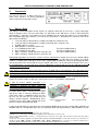
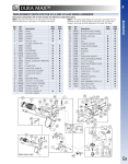
®
INSTALLATION MANUAL
FLARM COLLISION WARNING UNIT
Status
Software Version 3.00 (February 13, 2006)
© 2003-2006 FLARM Technology GmbH
Zurich-Switzerland
www.flarm.com
[email protected]
INSTALLATION MANUAL FLARM COLLISION WARNING UNIT
1.
Welcome to the FLARM user community
Thank you for purchasing FLARM, a modern low-cost collision-warning unit for sailplanes and light aircraft.
The main task for FLARM is to support the pilot, while he scans the airspace ahead with his own eyes.
FLARM is simple to use and does not distract the pilot from the main business in hand.
Sport flying is an activity that is associated with considerable risks for crew, passengers, third parties and
other objects. In order to make full and safe use of FLARM, it is absolutely essential to be fully aware
of the risks, operating conditions, restrictions and limitations associated with the use of FLARM.
This includes familiarity with and observance of the Operating Manual and the Installation Manual.
Additional configuration information can be found in the 'Data Port Specifications' document.
We always welcome suggestions for the improvement of FLARM.
The latest version of this handbook and other related documents can be found at the Website
www.flarm.com. This Website also has answers to Frequently Asked Questions.
This Website also carries announcements when new software versions or functions are available. If you
enter your name on the mailing list, you will automatically receive notification of changes as and when they
happen: www.flarm.com/mailman/listinfo/user-list_flarm.com
Software-Versions 3.x will only remain operational until the end of February 2008. After this date, you must
update the device in order to use it in the air. On publication, the update will have no functional changes and
can be downloaded free of charge. Users will be able to load the software with the aid of a suitable power
supply/data cable (not supplied). This operation requires the user to have the unit Serial Number to hand.
Software validity has to be time-limited to ensure that all FLARM units are mutually compatible and updates
include the latest obstacle data.
2.
How it works
FLARM receives position and movement information from an internal 16 channel GPS receiver with an
1
external antenna. A pressure sensor further enhances the accuracy of position measurements. The
predicted flight path of a first aircraft - in which FLARM is installed - is calculated by FLARM and the
information transmitted by radio, as a low power digital burst signal at one-second intervals. Provided they
are within receiving range these signals are received by further aircraft also equipped with FLARM. The
incoming signal is compared with the flight path calculated and predicted for the second aircraft. At the same
time, FLARM compares the predicted flight path with known obstacle data, including electric power lines,
radio masts and cable cars.
If FLARM determines the risk of dangerous proximity to one or more aircraft or obstacles, the unit gives the
pilot warning of the greatest danger at that moment. The warning is given by a whistle sound (beep) and
bright light emitting diodes (LED). The display also gives indication of the threat level, plus the horizontal and
1
vertical bearing to the threat.
The operating range is very dependent upon the antenna installation in the aircraft. The normal range is
about 2 km, but up to 5 km may be achieved in individual cases.
The GPS and collision coordinates of the other aircraft can also be made available for use in other systems
(e.g. external display, speech synthesizer, PDA) via a serial data output. There are a number of
manufacturers for such equipment.
In addition, FLARM operates as an IGC compatible flight data recorder if this software option has been
configured.
1
Requires Hardware Version 2 or higher. However, the vertical bearing on the serial data output is also available to third-party
equipment on Hardware Version 1.
Version 3.00E
Page 2 of 7
February 13, 2006
INSTALLATION MANUAL FLARM COLLISION WARNING UNIT
3.
General Advice on Installation
Installation and operation must be on the basis of non-interference with and no hazard to the existing suite of
other certified equipment necessary for safe flying operation, or installed to comply with official requirements.
Installation and operation must comply with official regulations and requirements. When FLARM is
permanently installed in an aircraft in Switzerland, the installation must comply with the 'Installation Policy'
published by the Swiss Civil Aviation Authority (FOCA). In Germany, an installation as portable device is
possible in gliders and motor-gliders; if an installation in powered aircraft is considered, European
Commission Regulation (EC) No 1702/2003 must be respected.
FLARM must be secured in such a position that the pilot has the display LEDs in direct view, and can hear
the acoustic warning tone and operate the control buttons. FLARM must not obstruct the piloting operation
and in particular it must not hinder his field of view. These requirements must be maintained at all times
during conditions of strong turbulence and acceleration. FLARM is not suited for use in conjunction with night
vision systems, night flying (no dimmers) or in pressurised cabins.
Ideally, FLARM will be installed under the instrument panel on the central console or on the cockpit sidewall.
The rear face of FLARM must face in the direction of flight. If FLARM is also equipped with an external
display and operating unit, then it may be installed elsewhere and another orientation. Usually, such an
installation requires an external radio antenna.
It is usually best to install FLARM in such a position that the power/data-socket is easily reached from a PC
with an extension cable. This simplifies downloading the latest obstacle data and software, and configuring
the unit. When updating software, the user must know the unique FLARM unit serial number.
If possible, FLARM should be so installed that the pilot does not inadvertently touch the push-button during
cockpit ingress and egress.
Cables must not be folded or under tension. The installation must allow adequate space for cable connectors
and the internal antenna.
FLARM, the radio antenna (if the internal antenna is not used) and the GPS antenna should each be
installed at least 25 cm away from the magnetic compass, more if possible.
After installation, an appropriate entry should be made in the aircraft technical logs and a check made that
the installation is in no way detrimental to the performance of mechanical, electrical or magnetic (e.g.
compass) performance of other aircraft systems (e.g. radio). The unit serial number and software version
should be recorded in the aircraft technical log. In the case of a permanent installation, the 'Means of
Compliance' should be confirmed in the aircraft technical log, and an 'AFM Supplement' carried in the
aircraft.
4.
Housing
The lower face of the housing has two threads, so that FLARM can easily be secured by two M5 screws (no
more than 12 mm long). This thread is in widespread use in gliding. FLARM should be installed on a flat
surface so that the housing is not subject to any mechanical stress. Alternatively, the unit may be secured by
the housing upper face.
®
The housing can be repeatedly fitted and removed using the DualLock supplied with the unit. The unit
comes supplied with two self-adhesive 12.5x25 mm fixtures. Care should be taken to ensure that the
bonding strength is very strong on both halves and difficult to detach.
The housing lower face also has two Phillips screws holding the two halves of the housing together. These
screws must not be over-tightened. By opening the housing, all guarantees relating to the equipment
become null and void.
The housing upper face is not sealed and care should be taken not to allow ingress of solid particles or
liquids. Should the unit become wet, it must be thoroughly dried prior to use. Condensation may occur if the
unit is subjected to sudden massive cooling. The housing should only be cleaned with a slightly moist nonabrasive cloth without any cleaning agents. The housing can be damaged by scratches and abrasion.
The plastic housing is black to minimise glare and has been tested at temperatures from -10 °C to +60 °C
and should be protected from excessive direct or indirect solar heating. Even if not subject to mechanical
stress, the housing may be deformed at temperatures upwards of +84 °C, and can also be deformed at lower
temperatures in the presence of mechanical stress. The unit should not be exposed to strong locally focused
solar radiation. Care should be taken when the cockpit canopy is open (lens effect fire hazard).
Version 3.00E
Page 3 of 7
February 13, 2006
INSTALLATION MANUAL FLARM COLLISION WARNING UNIT
5.
Connectors
The red rear face has an MCX socket for an
active GPS antenna, an RJ45 power/data
socket and an RJ12 extension socket.
6.
Power / Data
The eight-pin RJ45 power/data socket accepts an eight-pin connector (if necessary, a six-pin connector)
which is locked in place. The pin connections are generally² in-line with those set out in IGC GNSS FR
2
Specifications , so that the same cables may be used both in the air and on the ground, as used for modern
IGC compatible flight data recorders. The key to the connections is defined by the sequence from left to
3
right, not the numbering :
1.
2.
3.
4.
5.
6.
7.
8.
+8 to +26 VDC (recommended +12 VDC), liked with Pin 2 inside the unit
+8 to +26 VDC (recommended +12 VDC), linked with Pin 1 inside the unit
4
FLARM supplies +3 VDC
GND, with Pin 7 and 8 linked to the unit
Tx = FLARM transmits data
(PC-side to SUB-D9 Pin 2)
Rx = FLARM receives data
(PC-side to SUB-D9 Pin 3)
GND (' negative'), linked with Pin 8 inside the unit
(PC-side to SUB-D9 Pin 5)
GND (' negative'), linked with Pin 7 inside the unit
During flight operations at least Pins 2 and 7 must be connected. An 8-pole (or if necessary 6-pole) ribbon
cable with an RJ45 push-fit connector, or an 8-pole twisted-pair patch cable with RJ45 adapter, are equally
5
suitable. A suitable patch cable open at one end is supplied with FLARM unit and must be configured to the
aircraft connector in the aircraft. When using an 8-pole cable, Pins 1=2 must be joined. Likewise Pins 7=8. If
the remaining wires are not used, they must be individually insulated and must not be soldered or twisted
together -- not even in pairs.
There must be a direct electrical connection between FLARM and the aircraft battery. This connection must
be via a 500 mA fuse. Essential electrically-operated flight instruments must not draw their power through
FLARM fuse. It must be possible for the pilot to interrupt the power supply to FLARM during flight by means
of a switch or circuit breaker without affecting other essential aircraft systems. This might be necessary if the
pilot suspects that FLARM may be interfering with another on-board system, the suspected presence of
smoke, the smell of smoke, or flying in a country where the use of FLARM is not permitted.
In spite of reverse polarity protection, it is
important to check for correct polarity during
installation; in particular the power supply and
data wires must not be interchanged. The
transparent connector allows for a visual check of
the cable colour codes, ensuring that the open
end of the cable is correctly configured. When
using patch cables, neighbouring wires on Pins
Pin 1/2, 3/4, 5/6 and 7/8 are usually (but not
always) twisted together. Neighbouring wires
usually have the same colour, though one of the
pair has a colour alternating with white.
+12V
GND
Connector with pin numbers,
tab down
Open ended patch cable
In normal configuration Pin 5 transmits the most important NMEA-0183 Version 2.0 compatible GPGGA and
GPRMC codes at a configurable data rate (see document 'Data Port Specifications'); from Hardware version
2
Chapter 2.7.2.2.7.2, www.fai.org/gliding/gnss/tech_spec_gnss.pdf
FLARM uses pin numbering in-line with IGC specifications. The numbering is in reverse order.
4
When using FLARM Hardware Version 1 a Jumper links Pins 12 and 14 on the PCB. Units delivered ex-works have this jumper
already installed.
5
In the case of the cables supplied since March 2005 bearing the legend BLACK BOX on cable and connector, the connections are
usually as follows: GND = orange / orange-white, +12V = brown / white-brown. It is necessary to check the polarity prior to
connection. When supplying two or more units, only one single cable will be supplied, to be cut in half.
3
Version 3.00E
Page 4 of 7
February 13, 2006
INSTALLATION MANUAL FLARM COLLISION WARNING UNIT
2 also Garmin proprietary PGRMZ codes with barometric altitude information. Further codes are provided for
third party applications (e.g. external displays). These are described in a separate document 'Data Port
Specifications'. This document also describes how FLARM software may be configured. A PC application
exists for this.
After switching on and the self-test routine, the unit must first capture satellite signals to establish position.
Even if the antenna has a clear view of the sky, this process can take a few minutes. For this reason a glider
tug pilot should leave FLARM switched on during brief waiting periods between flights. During night flights
FLARM must be switched off.
Only the power/data socket to the unit may be used for updating FLARM software or obstacle data from the
PC. During this process FLARM must be disconnected from other equipment.
7.
Extension
Six or 4-pole connectors may be inserted in the 6-pole RJ12 socket. The connections to the pins are the
same as for Pins 2 and 7 described above. This socket is intended for use by third party applications (e.g. for
an external display via an uncrossed cable) and is regulated by a constant 4.8 kBaud. This socket must
neither be used for power supply nor for PC-communication (update, download, configuration).
This socket is not provided in Hardware Version 1; the power/data socket with and 8- (or if necessary 6-)
pole Y-intermediate connector should be used for external applications. In this case all third party
applications have access to only one single data rate, but which may be configured. Details can be found in
the document 'Data Port Specifications'.
When updating the external display it is necessary to press the update button on FLARM four times in quick
succession. FLARM responds by lighting all the anti-collision LEDs twice. FLARM should then be
disconnected from the power supply and then connected to the display; in the case of FLARM Hardware
Version 2 this must be to the extension-port. The display is updated the next time the unit is connected to the
power supply. For the next approx. 50 seconds the display alternately flashes the left and right LEDs. After
the update has been completed both top external display LEDs illuminate; if not, the entire procedure must
be repeated. FLARM must then be disconnected from the power supply. This procedure must be completed
once for each display.
8.
GPS
The external GPS antenna supplied with the unit must be connected; FLARM will not operate without an
adequate GPS signal. The cable length of the 50Ω RG-174U cable with MCX connector is about 2.5 m;
cables of other length are not available from FLARM Technology. A specialist must undertake any
shortening of the cable, which must not be cut to less than 0.5 m. Antenna splitters must not be used.
The antenna should be horizontal in straight flight and have a generally unobstructed view of the sky,
including during turns. The antenna should not have any electrically conducting surfaces (e.g. metal, carbon
fibre) above or immediately alongside. Ideally, the antenna will be located on top of the instrument panel.
Electrically conducting sheet metal under the antenna may enhance its performance.
The antenna base contains magnets, but nevertheless requires additional attachments. The antenna must
under no circumstances interfere with correct compass operation. If the antenna interferes with the compass,
the magnets in the antenna base must be removed with a screwdriver and the metallic foil put back.
If the aircraft is fitted with two or more GPS antennae, they should be separated if possible by at least 25 cm;
the same holds good for FLARM radio antennae.
Version 3.00E
Page 5 of 7
February 13, 2006
INSTALLATION MANUAL FLARM COLLISION WARNING UNIT
9.
Radio Antenna
The middle of the housing upper face has an aperture onto which is screwed an 86 mm long internal λ/4
radio antenna onto a conventional SMA connector. The antenna must be fitted and removed with care. This
antenna is required for operation of FLARM, and the correct installation has a considerable effect upon
range for transmitter/receiver range, so the installation must be carefully considered. The antenna must be
vertical, allowing generally unobstructed radiation to the front and sides. It is theoretically possible to use an
inverted installation, but only when making exclusive use of an external display. Horizontal or inclined
installation is not acceptable. In particular, there should be no electrically conducting surfaces (metal, carbon
fibre) above or immediately alongside the antenna. The antenna must not be under stress or bent, e.g. by
the cockpit canopy).
FLARM Technology can supply alternative external dipole antennas with 1.0m and 2.5m feed cables, for
external installation and antenna extension cables (50Ω RG-174U on conventional SMA). No antennae or
cables may be used other than those listed above. An external antenna must be adequately earthed to the
airframe. Installation may only be in a Zone 2A or 3 as described in DO-160E Section 23.
10.
Sound Signal
The housing upper face has a number of holes to improve the transmission of sound from the internal emitter
to the cockpit. These holes must remain unobstructed. There is no intercom connector. Third-party
manufacturers have suitable intercom equipment that is compatible with FLARM.
11.
Limitations
FLARM is designed and built as a non-essential 'situation awareness only' unit to support the pilot, and
cannot always provide reliable warnings. In particular, FLARM does not give any guidance on avoiding
action. Under no circumstances should a pilot or crewmember adopt different tactics or deviate from the
normal principles of safe airmanship. The use of FLARM is solely at the discretion of the commander and his
crew. Operation must be preceded by thorough familiarisation by the commander or his delegated
crewmember with the Operating Manual.
FLARM can only warn the pilot of the presence of other aircraft that are also fitted with FLARM or compatible
equipment, or warn of obstacles that are stored in the internal data bank. FLARM does not communicate
with Mode A/C/S transponders, and remains undetected by ACAS/TCAS/TPAS or Air Traffic Control
systems. Likewise, FLARM does not communicate with TIS-B, FIS-B or ADS-B.
At present FLARM is not certified by the Civil Aviation Authorities and has not been tested in accordance
with the normal aviation requirements (e.g. DO-160E), therefore no EASA Form1 can be handed out.
FLARM software development is commensurate with Level E of DO-178B; in other words a failure of the unit
will have no effect upon aircraft operation and does not increase crew workload. The FLARM obstacle data
bank is not certified.
Air band radio frequency allocation and licensing conditions may vary from country to country. The aircraft
commander is solely responsible for ensuring that FLARM is operated in conformity with the respective
licensing conditions. No licence is required to operate FLARM in Switzerland.
Until further notice FLARM may not be used in the USA or Canada without written authority of FLARM
Technology, or in an aircraft that is registered and/or insured in the USA or Canada. Likewise, operation of
FLARM is forbidden in aircraft in which one or more of the occupants resides in or is a citizen of the USA or
Canada. Likewise, use of FLARM is forbidden if the aircraft concerned takes off from, makes an intermediate
or final landing in the USA or Canada.
FLARM Technology its associates, development team, suppliers, manufacturers and data suppliers accept
no responsibility for any damage or claims that may arise from use of FLARM.
Version 3.00E
Page 6 of 7
February 13, 2006
INSTALLATION MANUAL FLARM COLLISION WARNING UNIT
12.
Technical Data
The following data are provided without guarantee and may be altered at any time without notice.
Height:
Width:
Length:
Weight:
Power supply:
Power drain:
Serial Data:
GPS:
Radio:
Temperature:
Intercom:
Vibration:
Country of Origin:
25 mm housing (without internal radio antenna)
100 mm overall height (with internal radio antenna)
75 mm
111 mm housing (without cable connectors)
119 mm overall length (with push-buttons, without cable connectors)
125 g (with internal radio antenna, without cable, without GPS antenna)
external power supply 8.0 to 26.0 (peak voltage up to 28.0) V DC via RJ45,
recommended value 12 V DC, direct galvanic link to aircraft battery via an essential 500
mA circuit breaker; this must be separate from other essential aircraft power systems
FLARM has reverse polarity protection.
typically approx. 55 mA at 12 V DC, approx. 37 mA at 24 V DC (Normal operation
without warnings or external display),
a collision warning may double these values.
bi-directional RS232, compatible with NMEA-0183 Version 2.0, standard message
format GPRMC, GPGGA, data rate 4.8 to 57.6 kBaud, additional NMEA proprietary
sentences PFLA and PGRMZ (described in a separate document)
16-Channel WAAS/EGNOS compatible GPS engine, external 50Ω active antenna with
2.5m RG-174U cable, MCX connector, 3.3V, dimensions depending upon the antenna
used, usually rectangular 45x45 to 50x50 mm, oval or circular of approx. 12 mm
thickness.
SRD-F-Band 868.0 to 868.6 MHz (Europe), other frequencies depending upon
configuration
less than 1 % Duty Cycle, Peak Pulse Power10 mW (ERP),
internal λ/4 antenna (screw-fitted to conventional SMA connector),
Range approx 2 km, possibly up to 5 km, depending upon antenna and installation
Operation: -10 to +60 °C, storage: -20 to +70 °C,
no certification in accordance with DO-160E Sections 4 and 5
not provided, suitable third party units are available
Use in conditions of strong vibration or turbulence should be avoided or subsequently
checked prior to continued operation,
no certification in accordance with DO-160E Section 8
Switzerland, Harmonized System Customs Code 852610
Version 3.00E
Page 7 of 7
DECLARATION OF CONFORMITY
FLARM
Technology
GmbH,
Sonneggstrasse 64, CH-8006 Zürich,
declares that in typical configuration the
'FLARM Anti-Collision Warning Unit'
Hardware Versions 1 to 3 meets the
requirements of the CE Mark.
The radio conforms with the requirements
of EN 300 220-3:2000 (Power Class 9.The
EMC conforms with EN 301 489-3:2002-08
for a Class 3 SRD Device (equipment type
I). FLARM is a Class 1 item of radio
equipment as defined by R&TTE Directive.
The necessary tests and certification were
undertaken by Ascom Systec AG,
Hombrechtikon, Switzerland.
These documents may be inspected at the
premises of FLARM Technology by
arrangement through: [email protected]
Zürich, March 2005
February 13, 2006