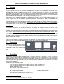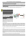
1
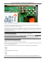
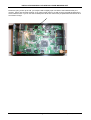
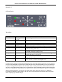
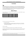
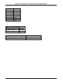
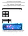
INSTALLATION MANUAL
OzFLARM Situation Awareness UNIT
Status
FLARM Software Version 3.07 (March, 2007)
OzFLARM Software Version 1.005 (Jan,2006)
© 2003-2006 FLARM Technology
© 2005-2006 RF Developments Pty Ltd
Boonah, Queensland,Australia
www.rf-developments.com
INSTALLATION MANUAL OzFLARM COLLISION-WARNING UNIT
Version Control.
1.0
Initial release
1.01
Revised Power up sequence notes. OzFALRM software now 1.004
1.02
Include version 2 hardware references
1.03
Tidy up power connection references
1.04
Correct dataport wiring mistakes
Version 1.03
Page 2 of 17
April 1st, 2006
INSTALLATION MANUAL OzFLARM COLLISION-WARNING UNIT
1.
Welcome to the community of FLARM users
Thank you for purchasing OzFLARM, a modern low-cost situation awareness unit for sailplanes and light
aircraft. The main task for OzFLARM is to support the pilot, while the pilot scans the airspace ahead with his
own eyes. FLARM is simple to use and does not distract the pilot from the main responsibility in hand.
Sport flying is an activity that is associated with considerable risks for crew, passengers, third parties and
other objects. In order to make full and safe use of OzFLARM, it is absolutely essential to be fully
aware of the risks, operating conditions, restrictions and limitations associated with the use of
OzFLARM. This includes familiarity with and observance of the Operating Manual and this
Installation Manual. Additional configuration information can be found in the 'Data Port Specifications'
document.
We always welcome suggestions for the improvement of OzFLARM.
The latest version of this handbook and other related documents can be found at the Website www.rfdevelopments.com. This Website also has answers to Frequently Asked Questions.
This Website also carries announcements when new software versions or functions are available. If you
enter your name on the mailing list, you will automatically receive notification of changes as and when they
happen: [email protected]
Software-Versions FLARM 2.x will only remain operational until the end of February 2006. On publication,
the update will have no functional changes and can be downloaded free of charge ( current update is version
3.xx valid till Feb,2008 )). Users will be able to load the software with the aid of a suitable power supply/data
cable (not supplied). This operation requires the user to have the unit serial number to hand. Software
validity has to be time-limited to ensure that all FLARM units are mutually compatible and updates include
the latest ground obstruction data.
2.
How it works
Basically the OzFlarm unit consists of 2 core modules. The first is the FLARM microprocessor. This controller
is identical to the SwissFlarm system being used in Europe. The technology utilises the tried and proven
“Aircraft risk prediction Algorithims” and obstacle database. Additional to this OzFlarm also uses the standard
Flarm datalogger feature. Software updates are performed via the Flarm port which has identical
connections to the Swiss Flarm unit. The second module is the OzFLARM interface. This micro handles the
OzFlarm compass display and beep alert. Additional to display functions it has a future upgrade path when
coupled to a suitable ADS-B receiver, to start receiving and displaying ADS-B targets. OzFlarms micro also
looks after the housekeeping, power management etc. Updates to OzFlarm are performed via the OzFlarm
dataport. The same download cable can be used as in the Flarm port, both are pin identical. Additional to
providing access to the micro we also have an NMEA port available for connection to a moving map display
or other glide computers or PDA’s.
Note: This system is by default 100 percent compatible with FLARM from Europe. Europe and Australia
operate on a different frequency, contact FLARM if you require changing to the Australian channels if you
already have a Swiss Flarm unit. OzFLARM units going overseas in gliders for competitions, we can re
program your units to suit. Note that due to the different frequency span both systems will be degraded
slightly due to matching, however, they will still achieve a satisfactory result.
OzFLARM receives position and movement information from an internal 16 channel GPS receiver with an
internal antenna ( external can be connected by selecting the appropriate antenna switch configuration, see
appendix A ). A pressure sensor1 further enhances the accuracy of position measurements. The predicted
own flight path is calculated by the FLARM micro and the information transmitted by radio, as a low power
1
Requires Hardware Version 2 or higher. However, the vertical bearing on the serial data output is also available to third-party
equipment on Hardware Version 1.
Version 1.03
Page 3 of 17
April 1st, 2006
INSTALLATION MANUAL OzFLARM COLLISION-WARNING UNIT
digital burst signal at one-second intervals. Provided they are within receiving range these signals are
received by further aircraft also equipped with OzFLARM. The incoming signal is compared with the flight
path calculated and predicted for the other aircraft. At the same time, FLARM micro compares the predicted
flight path with known data on ground obstructions, including electric power lines, radio masts and cable cars
( only if the obstacle database is loaded ).
If FLARM determines the risk of dangerous proximity to one or more aircraft or ground obstructions, the unit
gives the pilot warning of the greatest danger at that moment. The warning is given by a Dee Dah sound
sound (2 tone high - Low), The relative direction LED rose will light depending on which direction a target is
received. Typically and green leds represent 1km or further away targets, and are not deemed dangerous.
Red indicates targets within 1Km and flashing red indicates a potential threat.
The operating range is very dependent upon the antenna installation in the aircraft. The normal range is
about 2 km, but up to 5 km may be achieved in individual cases such as ground stations ( use of external
high gain antennas, see options on RF Developments website ).
The GPS and aircraft situation coordinates of the other aircraft can also be made available for use in other
systems (e.g. external display, speech synthesizer, PDA) via a serial data output. There are a number of
manufacturers for such equipment.
In addition, OzFLARM operates as an IGC-compatible flight data recorder if this software option has been
configured ( logger is not IGC approved but fully functional including pressure height recording).
3.
General Advice on Installation
Installation and operation must be on the basis of non-interference with and no hazard to the existing suite of
other certified equipment necessary for safe flying operation, or installed to comply with official requirements.
Installation and operation must comply with official regulations and requirements. When OzFLARM is
permanently installed in an aircraft, the installation must comply with the 'Installation Policy' published by the
Civil Aviation and Safety Authority (CASA).
OzFLARM must be secured in such a position that the pilot has the display LEDs in direct view, that he can
hear the acoustic warning tone and operate the control buttons. OzFLARM must not obstruct the piloting
operation and in particular it must not hinder his field of view. These requirements must be maintained at all
times during conditions of strong turbulence and acceleration. OzFLARM is not suited for use in conjunction
with night vision systems, night flying (no dimmers) or in pressurised cabins.
Ideally, OzFLARM will be installed under the instrument panel on the central console or on the cockpit
sidewall. The rear face of OzFLARM must face in the direction of flight. If OzFLARM is also equipped with an
external display and operating unit, then it may be installed elsewhere and another orientation. Usually, such
an installation requires an external radio and GPS antenna.
It is usually best to install OzFLARM in such a position that the Power/Data socket are easily reached from a
PC with an extension cable. This simplifies downloading the latest ground obstruction data and software and
configuring the unit. When updating software, the user must know the unique OzFLARM unit serial number.
If possible, OzFLARM should be so installed that the pilot does not inadvertently touch the push button
during cockpit ingress and egress.
Cables must not be folded or be under tension. The installation must allow adequate space for cable
connectors and the external vertical antenna.
OzFLARM, the external radio antenna and the GPS antenna ( optional ) should each be installed at least 10
cm away from the magnetic compass, more if possible.
After installation, an appropriate entry should be made in the aircraft technical logs as to reflect an
installation performed under a “no interference, no hazard basis” as is the case for glide computers and PDA
displays, as well as other GPS devices. You as the installer must observe this rule. Additional tests under a
no interference basis might include the operation of the radio and a check that OzFlarm causes no
interference to its normal operation. Checks that other aircraft systems do not interfere with OzFLARM are
also needed. The best method is to fly with a friend at a distance around 2 kms, make sure all systems are
off ( i.e, other GPS, vario and glide computer), observe his lit target LED and maintain that distance. Turn on
each piece of equipment and note any change. Acceptable operation is one that is not affected by other
devices. Should a problem occur then consult our FAQ page.
Version 1.03
Page 4 of 17
April 1st, 2006
INSTALLATION MANUAL OzFLARM COLLISION-WARNING UNIT
4.
Housing
The lower face of the housing has two threads, so that OzFLARM can easily be secured with two M5 screws
(no more than 10 mm long). This thread is in widespread use in gliding and 2 screws are provided with each
unit. OzFLARM should be installed on a flat surface so that the housing is not subject to any mechanical
stress.Make sure the top area of the housing is not covered by any ferrous material as the internal GPS
antenna is housed here. If it has to be mounted lower in the panel or covered then use of the optional
external antennas will be required. These can be purchased on the web site.
The housing can be repeatedly attached and released using the DualLock® supplied with the unit. The unit
comes supplied with two self-adhesive 12.5x25 mm fixtures. Care should be taken to ensure that the
bonding strength is very strong on both halves and difficult to detach.
The lower face of the housing also has two Phillips screws that hold the two halves of the housing together.
These screws must not be over-tightened. Avoid opening the case unless you need to ( i.e, select external
GPS antenna option ) If you need to select the GPS antenna option, please do not overtoghten the PCB to
housing screws.
Should the unit become wet, it should be thoroughly dried prior to use. Should the unit be massively cooled
condensation may occur. The housing should only be cleaned with a slightly moist non-abrasive cloth
without any cleaning agents. Scratches and abrasion can damage the housing.
The ABS polycarbonate plastic housing is black to minimise glare and has been tested at temperatures from
-10 to +60 °C. Efforts should be made to prevent exposure to excessive direct or indirect solar heating. Even
if not subject to mechanical stress, the housing may be deformed at temperatures upwards of +84 °C, and
can also be deformed at lower temperatures in the presence of mechanical stress. The unit should not be
exposed to strong locally focused sun radiation, therefore care should be taken when the cockpit canopy is
open (lens effect fire hazard).
*Note, we recently had units installed on dashes at a comp, the outside temp was only 30 degrees C but
inside under the plastic the cases were red hot and deformed! You must provide a cover or mount under the
visor on top of the instrument panel otherwise the plastic WILL distort and cause damage.
5.
Connectors
The red rear face has an MCX socket
for an active GPS antenna, an RJ45
Power/Data ( Flarm port ) socket and
an RJ45 Extension socket (OzFlarm
port ).
6.
Power/Data
The eight-pin RJ45 Power/Data socket accepts an eight-pin connector (if necessary, a six-pin connector)
that is locked in place. The pin connections are largely in-line with those set out in IGC GNSS FR
Specifications2, so that the same cables may be used both in the air and on the ground, as used for modern
IGC-compatible flight data recorders. The key to the connections is defined by the sequence from left to
right, not the numbering3:
FLARM Port ( left hand side socket )
1.
2.
3.
4.
5.
6.
7.
8.
2
3
+6 to +26 VDC (recommended +12 VDC), linked with Pin 2 inside the unit
+6 to +26 VDC (recommended +12 VDC), linked with Pin 1 inside the unit
FLARM supplies +3 VDC
GND, with Pin 7 and 8 linked to the unit
Tx = FLARM transmits data
(PC-side to SUB-D9 Pin 2)
Rx = FLARM receives data
(PC-side to SUB-D9 Pin 3)
GND ('negative'), linked with Pin 8 inside the unit
(PC-side to SUB-D9 Pin 5)
GND ('negative'), linked with Pin 7 inside the unit
Chapter 2.7.2.2.7.2, www.fai.org/gliding/gnss/tech_spec_gnss.pdf
FLARM uses Pin-numbering in-line with IGC specifications. The usual numbering is in reverse order.
Version 1.03
Page 5 of 17
April 1st, 2006
INSTALLATION MANUAL OzFLARM COLLISION-WARNING UNIT
During flight operations at least Pins 2 and 7 must be connected. An 8-pole (or if necessary 6-pole) ribbon
cable with an RJ45 push-fit connector, or an 8-pole twisted-pair patch cable with RJ45 adapter, are equally
suitable. A suitable patch cable open at one end is supplied with FLARMi and must be configured to the
aircraft connector in the aircraft. When using an 8-pole cable, Pins 1=2 must be joined. Likewise Pins 7=8. If
the remaining wires are not used, they must be individually insulated and must not be soldered or twisted
together - not even in pairs.
Additional note.On the supplied cables Blue goes to pin 2 , orange/white to pin 3 and blue white to
pin 5. If making a plug to go to a PDA then use a DB15 male and swap pins 2 and 3.
There must be a direct electrical connection
between FLARM and the aircraft battery. This
connection must be secured with a 500 mA fuse.
Essential electrically operated flight instruments
must not draw their power through the FLARM
fuse. It must be possible for the pilot to interrupt
the power supply to FLARM during flight by
means of a switch or circuit breaker without
affecting other essential aircraft systems. This
might be necessary if the pilot suspects that
FLARM may be interfering with another on-board
system, the suspected presence of smoke, the
smell of smoke, or flying in a country where the
use of FLARM is not permitted.In spite of the
reverse polarity protection, it is important to
check for correct polarity during installation; in
particular the power supply and data wires must
not be interchanged. The transparent connector
allows for a visual check of the cable colour
codes, ensuring that the open end of the cable is
correctly configured. When using patch cables
neighbouring wires on Pins Pin 1/2, 3/4, 5/6 and
7/8 are usually (but not always) twisted together.
Neighbouring wires usually have the same
colour, though one of the pair has a colour
alternating with white.
+12V
GND
Connector with Pin numbers,
tab down
Open ended Patch Cable
In normal configuration Pin 5 transmits the most important NMEA-0183 Version 2.0 compatible GPGGA and
GPRMC codes at a fixed data rate of 19.2KB * NOTE : under no circumstances must this speed be
changed otherwise the display section and alarms will cease to work (see document 'Data Port
Specifications'); from Hardware version 2 also Garmin proprietary PGRMZ codes with barometric altitude
information. Further codes are provided for third party applications (e.g. external displays). These are
described in a separate document 'Data Port Specifications'. This document also describes how FLARM may
be configured. A PC application exists for this called “FLARMTOOL”.
A separate P.C downloading program is supplied for updating the OzFLARM display software ( See software
manual )
After switching on (Depress UP the ON switch) and the self-test routine, the unit must first capture satellite
signals to establish position. Even if the antenna has a clear sky-view, this process can take a few minutes.
The GPS LED will be red, extinguishing when it has lock. If it remains red for more than 2 minutes then
check that the top surface is not covered by a metallic object. RED LED will stop the FLARM from working!
Because the unit can take a minute or two to lock onto a GPS signal a glider tug pilot should leave
OzFLARM switched on during brief waiting periods between flights. During night flights OzFLARM must be
switched off.
Only the Power/Data socket to the unit may be used for updating FLARM software or obstruction data from
the PC. During this process OzFLARM must be disconnected from other equipment.
Version 1.03
Page 6 of 17
April 1st, 2006
INSTALLATION MANUAL OzFLARM COLLISION-WARNING UNIT
7.
Extension
An 8-pole connector may be inserted in the 8-pole RJ45 socket on the right side looking from the rear. The
connections to the pins are the same as for Pins 1 and 8 described above. This socket is intended for use by
third party applications (e.g. for glide computers requiring NMEA GPS output or other PDA displays)
Settings for the GPS speed and message type can be done using the FLARMtool software.
FLARM Port ( Right hand side socket )
1.
2.
3.
4.
5.
6.
7.
8.
+6 to +26 VDC (recommended +12 VDC), linked with Pin 2 inside the unit
+6 to +26 VDC (recommended +12 VDC), linked with Pin 1 inside the unit
GPS Data out ( RS 232 levels ) NMEA or Ublox sentences,4800BPS GPRMC and GPGGA
GND, with Pin 7 and 8 linked to the unit
Tx =OzFLARM transmits data
(PC-side to SUB-D9 Pin 2)
Rx = OzFLARM receives data
(PC-side to SUB-D9 Pin 3)
GND ('negative'), linked with Pin 8 inside the unit
(PC-side to SUB-D9 Pin 5)
GND ('negative'), linked with Pin 7 inside the unit
Note. You can plug into either dataport with the power connection as they are identical and there is no risk of
damaging the unit.
8.
GPS
All Ozflarm units come with an internal GPS antenna which radiates through the top of the housing, this
means that by just adding power the unit will run with no requirement for an external GPS antenna. If you
require the use of an external GPS antenna you must do the following:
Hardware version 1 , serial numbers 100 to 199
Remove the 2 housing screws that secure the top lid to the main box, you may have to lightly manoeuvre the
lid out to clear the rear plastic lenses.
Locate the GPS board on the top lid, you will note 5 screws holding to the lid. Remove these, carefully note
their positions as there are 2 types of screws.
Looking at the component side of the PCB you will notice a 3 position dip switch near the antenna connector.
The top and middle switch will be ON, the bottom OFF. Switch the top 1 and 2 to the OFF position ( hard left
) and the bottom switch ON. The external GPS antenna is now selected.
Relocate PCB and insert screws. DO NOT over tighten, a light tension is all that is needed.
Version 1.03
Page 7 of 17
April 1st, 2006
INSTALLATION MANUAL OzFLARM COLLISION-WARNING UNIT
Picture – Both halves open, ready to undo top 5 screws
Picture - Default internal GPS antenna selected
Version 1.03
Page 8 of 17
April 1st, 2006
INSTALLATION MANUAL OzFLARM COLLISION-WARNING UNIT
Picture – external GPS antenna selected.
This completes the external GPS selection. Plug in a suitable antenna into the GPS socket on the rear.
Antennas can be purchased from RF Developments.
The cable length of the 50Ω RG-174U cable with MCX connector is about 2.5 m; cables of other length are
not available from RF Developments. A specialist must undertake any shortening of the cable, which must
not be cut to less than 0.5 m.
The external GPS antenna should be horizontal in straight flight and have an unobstructed sky-view, also
during turns. The antenna should not have any electrically conducting surfaces (e.g. metal, carbon fibre)
above or immediately alongside. Ideally, the antenna will be located on top of the instrument panel.
Electrically conducting sheet metal under the antenna may enhance its performance.
The antenna base contains magnets, but nevertheless requires additional attachments. The antenna must
under no circumstances interfere with correct compass operation. If the antenna interferes with the compass,
the magnets in the antenna base must be removed with a screwdriver and the metallic foil reattached.
If the aircraft is fitted with two or more GPS antennae, they should be separated if possible by at least 25 cm;
the same holds good for FLARM radio antennae.
Hardware version 2 , serial numbers 201 to xxx ( current )
Remove the 2 housing screws that secure the top lid to the main box, you may have to lightly manoeuvre the
lid out to clear the rear plastic lenses.
Locate the 3 position dip switch on the main PCB. This has 3 slide switches with the defaults being :
3 = ON
2 = ON
1 = OFF
To select external GPS then it should be:
3 = OFF
2 = ON
1 = OFF
To re assemble extreme care must be used. The top lid ( GPS section ) has 10 pins sitting beneath it for
insertion into the main PCB. Carefully line these up and at the same time check that the plastic front and rear
Version 1.03
Page 9 of 17
April 1st, 2006
INSTALLATION MANUAL OzFLARM COLLISION-WARNING UNIT
lenses are going to line up as well, you maybe need to slightly open one side to see inside that the pins
connect . Some care and this will work. If you have trouble return to us with a return pre paid sachel and we
will re install for free. If you do not want to attempt this at all then return with pre paid sachel and we will do it
at no labour charge.
Version 1.03
Page 10 of 17
April 1st, 2006
INSTALLATION MANUAL OzFLARM COLLISION-WARNING UNIT
9.
Radio Antenna
The rear of the housing has an SMA connector onto which is screwed an 86 mm long internal λ/4 radio
antenna. The antenna must be fitted and removed with care. This antenna is required for operation of
OzFLARM, and the correct installation has a considerable effect upon range for transmission and reception,
so the installation must be carefully considered. The antenna must be vertical, allowing generally
unobstructed radiation to the front and sides. It is theoretically possible to use an inverted installation, but
only when making exclusive use of an external display. Horizontal or inclined installation is not acceptable. In
particular, there should be no electrically conducting surfaces (metal, carbon fibre) above or immediately
alongside the antenna. The antenna must not be under stress or bent, e.g. by the cockpit canopy).
RF Developments can supply alternative external dipole antennas with 1.0m and 2.5m feed cables, for
external installation and antenna extension cables (50Ω RG-174U on conventional SMA). No antennae or
cables may be used other than those listed above. An external antenna must be adequately earthed to the
airframe. Installation may only be in a Zone 2A or 3 as described in DO-160E Section 23.
10.
Sound Signal
The front face has a hole to improve the transmission of sound from the internal emitter to the cockpit. This
hole must remain unobstructed. There is no intercom connector. The volume control will increase or
decrease the audio. Third-party manufacturers manufacture suitable intercom equipment that is compatible
with OzFLARM that can give audable alerts for powered aircraft.
11.
Limitations
FLARM and OzFLARM are designed and built as a non-essential situation awareness only unit to support
the pilot, and cannot always provide reliable warnings. In particular, OzFLARM does not give any guidance
on avoiding action. Under no circumstances should a pilot or crewmember adopt different tactics or deviate
from the normal principles of safe airmanship. The use of OzFLARM is solely at the discretion of the
commander and his crew. Operation must be preceded by thorough familiarisation by the commander or his
delegated crewmember with the Operating Manual.
OzFLARM can only warn the pilot of the presence of other aircraft that are also fitted with OzFLARM or
compatible equipment, or warn of obstructions that are stored in the internal data bank. OzFLARM does not
communicate with Mode A/C/S transponders, and remains undetected by ACAS/TCAS/TPAS or Air Traffic
Control systems. Likewise, OzFLARM does not communicate with TIS-B, FIS-B or ADS-B.
The use of OzFLARM is at the sole responsibility and discretion of the aircraft commander or his delegated
crewmember. Operation must be preceded by full familiarisation with the equipment and careful study of the
Operating Manual.
At present OzFLARM is not certified by the Civil Aviation Authorities and has not been tested in accordance
with the normal aviation requirements (e.g. DO-160E). The FLARM software development s commensurate
with Level E of DO-178B; in other words a failure of the unit will have no effect upon aircraft operation and
does not increase crew workload. The OzFLARM obstruction data bank is not certified.
Air band radio frequency allocation and licensing conditions may vary from country to country. The aircraft
commander is solely responsible for ensuring that OzFLARM is operated in conformity with the respective
licensing conditions. No licence is required to operate OzFLARM in Australia.
Until further notice OzFLARM may not be used in the USA or Canada without written authority of FLARM
Technology, or in aircraft that is registered and/or insured in the USA or Canada. Likewise, operation of
FLARM is forbidden in aircraft in which one or more of the occupants resides in or is a citizen of the USA or
Canada. Likewise, use of FLARM is forbidden if the aircraft concerned takes off from, makes an intermediate
or final landing in the USA or Canada.
RF Developments, its associates, development team, suppliers, manufacturers and data suppliers accept no
responsibility for any damage or claims that may arise from use of OzFLARM.
Version 1.03
Page 11 of 17
April 1st, 2006
INSTALLATION MANUAL OzFLARM COLLISION-WARNING UNIT
12.
Technical Data
The following data are provided without guarantee and may be altered at any time without notice.
Height:
Width:
Length:
Weight:
Power supply:
Power drain:
Serial data:
GPS:
Radio:
Temperature:
Intercom:
Vibration:
Country of Origin:
25 mm housing (without internal radio antenna)
100 mm overall height (with internal radio antenna)
75 mm
111 mm housing (without cable connectors)
119 mm overall length (with push button, without cable connectors)
155 g (with internal radio antenna, without cable, without GPS antenna)
external power supply 6.0 to 28.0 (peak voltage up to30.0) VDC via RJ45,
recommended value 12 VDC;
direct galvanic link to aircraft battery via an obligatory 500 mA circuit breaker,
separated from essential aircraft systems;
OzFLARM has a reverse polarity protection
typically approx. 55 mA at 12 VDC, approx. 37 mA at 24 VDC
(normal operation without warnings or external display),
a collision warning may double these values
bi-directional RS232, compatible with NMEA-0183 Version 2.0, standard message
format GPRMC, GPGGA, data rate 4.8 to 57.6 kBaud, additional NMEA proprietary
sentences PFLA and PGRMZ (described in a separate document)
16-Channel WAAS/EGNOS compatible GPS engine, external 50Ω active antenna with
2.5m RG-174U cable, MCX connector, 3.3V, dimensions depending upon the antenna
used, usually rectangular 45x45 to 50x50 mm, oval or circular of approx. 12 mm
thickness
SRD- -Band 915.0 to 928 MHz (Australia ), other frequencies depending upon
configuration
less than 1 % Duty Cycle, Peak Pulse Power 10 mW (ERP),
internal λ/4 antenna (screw-fitted to conventional SMA connector),
Range approx 2 km, possibly up to 5 km, depending upon antenna and installation
Operation: -10 to +60 °C, storage: -20 to +70 °C,
no certification in accordance with DO-160E Sections 4 and 5
not provided, suitable third party units are available
Use in conditions of strong vibration or turbulence should be avoided or subsequently
checked prior to continued operation,
no certification in accordance with DO-160E Section 8
Australia
Version 1.03
Page 12 of 17
DECLARATION OF CONFORMITY
Complies with AS/NZS 4268:2003
Low power transmitting and receiving
device.
RF Developments N-15142
ABN 60 789 837 451
This device must be operated in
accordance with the manufacturers
recommended installation and users
guide. Under no circumstances should
this equipment be modified.
Modifications will render the unit un
approved and removes all warranties.
April 1st, 2006
INSTALLATION MANUAL OzFLARM COLLISION-WARNING UNIT
Appendix A:
OzFlarm Basics
The LED’s
ON/OFF
GPS
TX/RX
Flashing GREEN
at 1 Hz
Flashing RED at
1 Hz
Off
Steady RED
OFF
Steady RED
Steady GREEN
Compass Rose
Above/Below
Plus/Level/Minus
Input Voltage is within normal limits
Input Voltage is OUTSIDE normal limits
The unit is turned OFF
GPS does not have LOCK ( Unit will not transmit )
GPS has lock if the unit is powered up
The unit is NOT transmitting its position, usually because
it does not have GPS lock
The unit is NOT receiving any other FLARM or OZFLARM units but is ready for use
The COMPASS ROSE displays the relative heading to any
aircraft that may be of interest.
Indicates that an aircraft is within a cone directly above or
below the aircraft
Indicates that an aircraft of interest is on a flight level
above, below or on the same flight level
FLARM’s range is subject to the antenna installation in the aircraft but usually is around 1 to 3 km, sufficient
even for high speed gliding. Alarms and the three alarm levels are issued depending on the forecasted time
to impact, not a geometrical distance. The first alarm level is usually issued 18 to 20 seconds, the second
one 13 to 15 seconds and the third one 8 to 10 seconds prior to the predicted impact and last as long as the
alarm level is appropriate. Depending on the impact forecast, alarm levels might even go down or disappear.
Alarms are highly selective, i.e. they are only issued when there is imminent danger. In an additional
information mode called “nearest mode”, the user can be informed about other aircraft in the vicinity even
when not posing any elevated danger.
Version 1.03
Page 13 of 17
April 1st, 2006
INSTALLATION MANUAL OzFLARM COLLISION-WARNING UNIT
Controls
Note:
Initial design allowed the user to manually turn ON or OFF the unit by holding the toggle UP for
one second. This feature has now been disabled as it was not practical for remote installations and
also in some circumstances the pilot could accidently remove power and the unit would be disabled
( like when switching from battery one to two ) The unit now power up when power is applied ,
with the green leds all lighting and a 2000 hz tone, and the red leds lighting and a 1800 Hz tone –
this test all the leds and sounds the two tones used.
Alarm Rose
When ALARM messages are displayed on the Compass Rose, they are ALWAYS RED. A number
of Alarm Levels exist
Time to Projected Impact
8-10 Seconds
13-15 Seconds
18-20 Seconds
> 20 Seconds
Alarm Level
3
2
1
0
Audible Alarm
Yes
Yes
No
No
Flash
Yes
No
No
No
The Alarm will sound under the following conditions.
•
•
Alarm Level increases
Relative Heading changes by more than 30 degrees since the last report, even though the
Alarm Level has not changed. [This is an indicator that a 2nd plane is in the area, and it is
more dangerous at the moment]
Alarm Acknowledge
The alarm is acknowledged by pressing the switch to the MODE position momentarily.
If you wish to silence the alarm for about five minutes this can be done by pressing the switch to the
MODE position for about two to 3 seconds. All the LEDS will light up green for half a second to
confirm activation
The COMPASS ROSE will be lit up in 45 degree segments. The segment pointing NORTH is from
-22.5 degrees to 22.5 degrees. Other segments line up accordingly.
Version 1.03
Page 14 of 17
April 1st, 2006
INSTALLATION MANUAL OzFLARM COLLISION-WARNING UNIT
0º-22.5º
22.5º-67.5º
67.5º-112.5º
112.5º-157.5º
157.5º-202.5º
202.5º-247.5º
247.5º-292.5º
292.5º-337.5º
337.5º-360º
North
North-East
East
South-East
South
South-West
West
North-West
North
Relative Vertical Height
At least 65m BELOW
BELOW
Less than +/-65m
MIDDLE
At least 65m ABOVE
ABOVE
Compass Rose Centre LED
Vertical Height > Horizontal Distance RED
Vertical Height < Horizontal Distance OFF
Version 1.03
Page 15 of 17
April 1st, 2006
INSTALLATION MANUAL OzFLARM COLLISION-WARNING UNIT
Other Important Planes Rose
The Compass Rose will also display position reports for other interesting planes. Not all planes in
the vicinity will be displayed.
Horizontal Distance < 1000 Meters and Vertical Clearance <300 Meters RED
Outside the above Cylinder
GREEN
0º-26º
26º-64º
64º-116º
116º-154º
154º-206º
206º-244º
244º-296º
296º-334º
334º-360º
North
North-East
East
South-East
South
South-West
West
North-West
North
Relative Vertical Height
At least 300m BELOW BELOW
Less than 300m
MIDDLE
At least 300m ABOVE ABOVE
OzFLARM indicating 1 target between immediate left and the next 45Deg led, this means in the
area between the 2. This is not necessarily 2 gliders! The bottom Led is indicating a glider behind.
The extreme left centre LED indicates all targets are at the same level +/- 65 metres ( 180ft )
Version 1.03
Page 16 of 17
April 1st, 2006
INSTALLATION MANUAL OzFLARM COLLISION-WARNING UNIT
Remember, OzFLARM is an aid to situation awareness, others must
be equipped with compatable Flarm/OzFLARM units – so spread the
word!
You must continue to use good lookout and fly safely.
Version 1.03
Page 17 of 17
April 1st, 2006