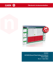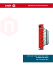
1
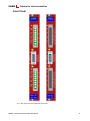
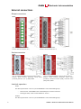
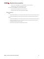
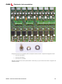
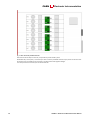
CAEN
Tools for Discovery
Electronic Instrumentation
2851
0
UM
Rev. 0 - 26 May 2014
Es
UM2851
A251x Series 50W LV Boards User Manual
Rev. 1 - 26 June 2014
Purpose of this Manual
This document is the A251x Series 50W LV Boards User Manual; it contains information about the installation, the
configuration and the use of the boards.
Change Document Record
Date
26 May 2014
26 June 2014
Revision
0
1
Changes
PRELIMINARY Release
Updated parameters p.13
Symbols, abbreviated terms and notation
T.B.D.
Reference Documents
Disclaimer
No part of this manual may be reproduced in any form or by any means, electronic, mechanical, recording, or
otherwise, without the prior written permission of CAEN SpA.
CAEN will repair or replace any product within the guarantee period if the Guarantor declares that the product is
defective due to workmanship or materials and has not been caused by mishandling, negligence on behalf of the User,
accident or any abnormal conditions or operations.
CAEN declines all responsibility for damages or injuries caused by an improper use of the Modules due to negligence on
behalf of the User. It is strongly recommended to read thoroughly the CAEN User's Manual before any kind of
operation. CAEN reserves the right to change partially or entirely the contents of this Manual at any time and without
giving any notice.
Disposal of the Product The product must never be dumped in the Municipal Waste. Please check your local regulations
for disposal of electronics products.
Made In Italy : We stress the fact that all the boards are made in Italy because in this globalized world, where getting
the lowest possible price for products sometimes translates into poor pay and working conditions for the people who
make them, at least you know that who made your board was reasonably paid and worked in a safe environment. (this
obviously applies only to the boards marked "Made in Italy", we cannot attest to the manufacturing process of "third
party" boards).
CAEN
Electronic Instrumentation
Index
1.
2.
A251x Series Overview ....................................................................................................... 4
Technical Specifications ...................................................................................................... 5
Channel Characteristic Table .................................................................................................................................... 5
Front Panel................................................................................................................................................................ 6
External connections ................................................................................................................................................ 7
Output connectors .................................................................................................................................................................7
Service connector...................................................................................................................................................................7
Interlock operation ................................................................................................................................................................7
Status operation .....................................................................................................................................................................8
3.
Channels in parallel................................................................................................................................................... 9
Safety and installation requirements ................................................................................ 12
General safety information ..................................................................................................................................... 12
Injury Precautions ................................................................................................................................................................12
4.
Safety Terms and Symbols on the Product ............................................................................................................. 12
Installation .............................................................................................................................................................. 12
Operating modes .............................................................................................................. 13
Output control and monitoring .............................................................................................................................. 13
PID (Proportional Integrative Derivative) Parameters .........................................................................................................14
List of Figures
Fig. 1 – Mod. A251x series front panel (8 pin & db 37 version) ...............................................................................................................6
Fig. 2 – Mod. A251x with paralleled channels .......................................................................................................................................11
List of Tables
Table 1 – Channel characteristics of the A251x LV Boards ......................................................................................................................5
3
UM2851 – A251x Series 50W LV Boards User Manual
CAEN
Electronic Instrumentation
1. A251x Series Overview
The Mod. A251x series are single width (5 TE wide) boards housing 8 LV floating channels, compatible with the
CAEN Universal Multichannel Power Supply System (SY1527, SY2527, SY3527, SY4527, SY5527). The floating return
allows on-load grounding reducing the noise level; the floating channels are insulated from each other and from
Ground up to ±150 V.
Each output channel is provided with individual remote sensing lines to compensate for the voltage drop over the
connection cables
The Maximum channel power is 50 W (connector output). Channels can be connected in parallel with modularity 2
or 4 to obtain higher output power (for 2/4 modularity Iset resolution is 100 mA and Imon resolution is 10 mA).
The available versions are the following:
Version:
A2517
A2518
A2519
Output Voltage:
1÷5 V
3÷8 V
5÷15 V
Max. Output Current:
15 A
10 A
5A
The Output Voltage RAMP-UP and RAMP-DOWN Times may be selected independently for each channel in the 1 ÷
200 ms range (1 ms step).
Safety features include:
OVERVOLTAGE: if a channel monitored voltage goes above the programmed Overvoltage threshold value (OVVThr),
it is signalled to be in "overvoltage" and is switched off.
UNDERVOLTAGE: when the monitored voltage goes below the programmed undervoltage threshold (UNVThr), the
channel is switched off
OVERCURRENT: if a channel tries to draw a current larger than its programmed limit, it is signalled to be in
"overcurrent" and is switched off.
The output channels can be enabled according to the interlock logic (see Interlock operation)
All versions are available either with 8 pin 0.15”pitch high current output connectors; A2518 and A2519 series are
provided also with db 37 output connectors.
A global enable/disable connector allows to disable the channels and it is also possible, via front panel logic signals,
to enable individually each channel (only for db 37 versions).
Channels are organized into groups, and the turning on/off of the channels within one group can be delayed up to
900ms (User programmable) between each other.
Channels feature a PID (proportional integrative-derivative) digital controller, whose parameters are User
programmable; in this way, the control loop can be optimized to any load.
UM2851 – A251x Series 50W LV Boards User Manual
4
Electronic Instrumentation
CAEN
2. Technical Specifications
Channel Characteristic Table
Table 1 – Channel characteristics of the A251x LV Boards
Version
A2517
Packaging
8 (Individual Floating)
Polarity
Floating
1÷5 V (connector output)
Voltage Ripple
Max. Output Current
15 A
< ±0.5%
Voltage Monitor Resolution
1 mV (connector and status)
Current Set Resolution
10 mA; 100 mA (2/4 modularity)
Current Monitor Resolution
1 mA ; 10 mA (2/4 modularity)
0÷6 V settable for each channel
Over/Under voltage thr. resolution
5
5A
1 mV
Vset Accuracy
Ramp Up/Down Time
10 A
0A
Voltage Set Resolution
Short Circuit Protection
5÷15 V (connector output)
50 W (firmware limited)
Minimum Load
Hardware OVV Protection
3÷8 V (connector output)
< 10 mV pp (T.B.C.)
Max. Ch. Output Power
Over/Under voltage thresholds
A2519
1 unit (5 TE) wide, 6U-high mechanics
No. of Channels
Output Voltage
A2518
2÷9 V settable for each channel
4÷16 V settable for each channel
10 mV
7.50V
9.75V
17.50V
Available
1÷200 ms ; 1 ms step
Turn on/off delay
0 ÷ 900ms
Transient response
Adjustable via PID controller
RTN – GND Isolation
±150V
Sense cable input impedance
1 kOhm
Enable inputs
Available
Status outputs
Available
Temperature range
5° ÷ 85° C
UM2851 – A251x Series 50W LV Boards User Manual
CAEN
Electronic Instrumentation
Front Panel
Fig. 1 – Mod. A251x series front panel (8 pin & db 37 version)
UM2851 – A251x Series 50W LV Boards User Manual
6
Electronic Instrumentation
CAEN
External connections
Output connectors
A251x
A251xA
Type: DC8W8SA00LF D-Sub 8W8
Function: Out Channels (0÷3; 4÷7)
Type: FCI DCPV37S300GT DB37
Function: Out Channels (0÷3; 4÷7)
Service connector
A251x
A251xA
Type: FCI ICD26S13E4GV00LF D-Sub SKT 26 POS 2.28mm
Function: Group Interlock (insulated); Group Status
(insulated); Status (0…3; 4…7); VAUX, DGND
Type: FCI ICD26S13E4GV00LF D-Sub SKT 26 POS 2.28mm
Function: Group Interlock (insulated); Group Status
(insulated); Individual Interlock (GND); Individual Status
(GND); VAUX, DGND
Interlock operation
A251x
One Group (channels 0..3 and 4..7) can be ENABLED in one of the following ways:
−
Short circuit IT- with DGND and IT+ with VAUX pins on service connector
−
Send signal 4÷6V, ~5mA current between IT- and IT+
A251xA
One Group (channels 0..3 and 4..7) can be ENABLED in one of the following ways:
7
UM2851 – A251x Series 50W LV Boards User Manual
Electronic Instrumentation
CAEN
−
Short circuit IT- with DGND and IT+ with VAUX pins on service connector
−
Send signal 4÷6V, ~5mA current between IT- and IT+
One channel can be ENABLED in one of the following ways:
−
Short circuit IT# with VAUX pins on service connector
−
Send signal 4÷6V, ~5mA current between IT# and DGND
Status operation
A251x
−
Contact closed between ST+ and ST- when no FAIL is present on one Group channel (0..3 and 4..7)
−
Contact open between ST+ and ST- when FAIL is present on one Group channel (0..3 and 4..7)
A251xA
−
Contact closed between ST+ and ST- when no FAIL is present on one Group channel (0..3 and 4..7)
−
Contact open between ST+ and ST- when FAIL is present on one Group channel (0..3 and 4..7)
−
Level high on ST# when no FAIL is present
−
Square wave (TTL grounded) on ST# when FAIL is present
UM2851 – A251x Series 50W LV Boards User Manual
8
Electronic Instrumentation
CAEN
Channels in parallel
The A251x boards are provided with six Connection Keys (four X keys and two Z keys), that allow to connect the
channels in parallel.
The X key allows to parallel two channels, the Z key allows to parallel four channels.
As two or four channels are paralleled, the system automatically recognizes the actual number of channels: two or
four paralleled channels are seen by the control software as one channel with double or quadruple output current
and power.
In order to connect the channels in parallel, follow these steps:
•
Remove ONLY the screws as indicated (orange circles)
•
Remove carefully the shield
•
Insert the Connection Keys between the channels to be paralleled
o
X key
Z key
o
9
Each connection key is provided with 2x3 pin male strips (two for X keys and four for Z keys)
The 2x3 strips must be plugged into the relevant sockets on A251x (named J20÷J27, see figure)
UM2851 – A251x Series 50W LV Boards User Manual
CAEN
Electronic Instrumentation
•
Secure the Connection Keys with the provided screws, grover washers, flat washers
All adjacent channels can be paralleled, with the exception of Channel 3 and 4. The pictured configuration shows:
•
Channels 0-1 paralleled
•
Channels 2-3 paralleled
•
Channel 4-5-6-7 paralleled
With this configuration the SYx527 system detects 3 channels (0, 2, 4); the lower channel index is assigned to the
paralleled channels.
UM2851 – A251x Series 50W LV Boards User Manual
10
CAEN
Electronic Instrumentation
Fig. 2 – Mod. A251x with paralleled channels
Once the Connection Keys are secured, it is possible to put the shield in place.
Remember that, at this point, it is necessary to short circuit the paralleled channels output; these connections must
be made as close as possible to the connectors, for both positive and negative voltages.
The same procedure is necessary for the Sense terminals.
11
UM2851 – A251x Series 50W LV Boards User Manual
CAEN
Electronic Instrumentation
3. Safety and installation requirements
General safety information
This section contains the fundamental safety rules for the installation and operation of the board. Read
thoroughly this section before starting any procedure of installation or operation of the product.
Injury Precautions
Review the following precautions to avoid injury and prevent damage to this product or any products
connected to it. To avoid potential hazards, use the product only as specified. Only qualified personnel
should perform service procedures.
Avoid Electric Overload.
To avoid electric shock or fire hazard, do not power a load outside of its specified range.
Avoid Electric Shock.
To avoid injury or loss of life, do not connect or disconnect cables while they are connected to a voltage
source.
Do Not Operate Without Covers.
To avoid electric shock or fire hazard, do not operate this product with covers or panels removed.
Do Not Operate in Wet/Damp Conditions.
To avoid electric shock, do not operate this product in wet or damp conditions.
Do Not Operate in an Explosive Atmosphere.
To avoid injury or fire hazard, do not operate this product in an explosive atmosphere.
Do Not Operate With Suspected Failures.
If you suspect this product to be damaged, have it inspected by qualified service personnel.
Safety Terms and Symbols on the Product
These terms may appear on the product:
DANGER indicates an injury hazard immediately accessible as you read the marking.
WARNING indicates an injury hazard not immediately accessible as you read the marking.
CAUTION indicates a hazard to property including the product.
The following symbols may appear on the product:
DANGER
WARNING
High Voltage
Refer to Manual
Installation
The A251x are single-width boards. At power ON the SYSTEM, the processor will scan all the slots in the
crate to find out where the module is plugged and what kind of module it is.
UM2851 – A251x Series 50W LV Boards User Manual
12
Electronic Instrumentation
CAEN
4. Operating modes
The A251x boards can be controlled, either locally or remotely, through the SYSTEM software interface.
For details on SYx527 System operation, please refer to the User's Manual of this product. The following
sections contain a description of commands available for the board control and status monitoring.
WARNING
THE MOD. A251x BOARD REQUIRE
SYSTEM FIRMWARE VERSION 2.00.01 OR LATER
Output control and monitoring
The following board parameters are available:
Parameter
Descritpion
BdStatus (monitor)
bit 0: PowerFail; if 1, failure in the channels local power supply
bit 1: Firwmare Checksum Error; if 1, error in the board firmware checksum
bit 2: HVMax Calibration Error; if 1, the board HVMax parameter (if present) is not calibrated
bit 3: Temperature Calibration Error; if 1, the board temperature sensor (if present) is not calibrated
bit 4: Under Temperature; if 1, the board temperature sensor (if present) signals a board temperature < 5 °C
bit 5: Over Temperature; if 1, the board temperature sensor (if present) signals a board temperature > 65 °C
bits 6..31: Reserved
OnGroup (settable)
Turn ON channel associated to the selected group
OffGroup (settable)
Turn OFF channel associated to the selected group
Intck A (settable)
Enable /disable operation of IT+/IT- signals of section A
Intck B (settable)
Enable /disable operation of IT+/IT- signals of section B
For each output channel, the following parameters are available:
13
Parameter
Descritpion
CHANNEL NAME (settable)
Descriptive name for the relevant channel
V0SET (settable)
Output voltage programmable value
I0SET (settable)
Current limit programmable value
UNVTHR (settable)
Set output under voltage threshold
OVVTHR (settable)
Set output over voltage threshold
RUpTime (settable)
Set voltage ramp-up time
RDWnTime (settable)
Set voltage ramp-down time
VMON (monitor)
Monitored voltage value
VCON (monitor)
Monitored connector voltage value
IMON (monitor)
Monitored current value
STATUS (monitor)
Displays the channel status
PW (ON/OFF)
Power parameter shows the ON/OFF channel status; when set to ON, the channel is switched on (if the
INTERLOCK is not active and if the channel is enabled either locally or remotely)
TripInt (settable)
2N-bit word (Dec. 0÷2^2N-1) max 16 lines, where N is the number of the board’s Internal Trip Bus lines.
Bits [0;N-1] allow the channel to sense the trip status from the corresponding lines when set to one; in
the same way, bits [N;2N-1] allow the channel to propagate the trip status over the Trip Bus: bit N on
line 0 and so on (see SY4527 User’s manual)
TripExt (settable)
Must be set in the 0÷255 range. Bits [0;3] allow the channel to sense the trip status from the
corresponding lines when set to one; in the same way, bits [4;7] allow the channel to propagate the trip
status over the trip bus: bit 4 on line 0 and so on (see SY4527 User’s manual)
ONGRDEL (settable)
Set ON delay between channel in the same group
OFFGRDEL (settable
Set OFF delay between channel in the same group
CHTOGROUP (settable)
Number of group to associate the channel
TEMP (monitor)
Monitored channel temperature
Intck
Enable/Disable operation of channel interlock signals (only A251xA versions)
UM2851 – A251x Series 50W LV Boards User Manual
CAEN
Electronic Instrumentation
All parameters can be changed when the channel is off. When the channel is switched on, only a variation of VSET in
a range of ± 5% is allowed, for adjustment purposes.
To ensure that two or more channels are turned on / off with delays programmed by user, these
channels must be assigned the same value of the ChToGroup parameter and the desired time must be
entered in the OnGrDel and OffGrDel parameters (0 = no delay). The switching on and off are performed
by entering the ChToGroup parameter value in the field OnGroup / OffGroup, (available as parameters
of the board).
The following messages may be returned by the SYSTEM when monitoring the channel status:
OFF
OVC
OVV
UNV
EXTTRIP
INTTRIP
EXT_DIS
PWR_FAIL
OVV_PROT
TEMP_ERR
(channel turned OFF)
(channel in OVERCURRENT condition)
(channel in OVERVOLTAGE condition)
(channel in UNDERVOLTAGE condition)
1
(channel OFF due to external TRIP line signal)
(channel OFF due to internal OVERCURRENT condition)
(channel disabled by board INTERLOCK protection)
(channel OFF due to a Power failure)
(channel with connector over voltage detected)
(channel over >85°C / under <5°C temperature)
PID (Proportional Integrative Derivative) Parameters
The channels implement a digital type controller. The user has the possibility to change the loop parameters (Kp, Ki
and Kd). These operations are not allowed by CAENGECO2020 Control Software, but they can be done only in
transparent mode (see SY4527 manual). By typing P from the main menu, it is possible to open the interface to
modify the PID coefficients of the channels. All changes of the coefficients are saved by typing S.
N.B. The PID coefficients can be modified when the channels are switched off. In case of change of the coefficients
with the channels on, a confirmation message asks authorization to turn off the channel and change the
coefficients.
1
EXTTRIP and INTTRIP parameters are expressed in Hexadecimal format
UM2851 – A251x Series 50W LV Boards User Manual
14
CAEN
Electronic Instrumentation
Tools for Discovery
CAEN SpA is acknowledged as the only company in the world providing a complete range of High/Low Voltage Power
Supply systems and Front-End/Data Acquisition modules which meet IEEE Standards for Nuclear and Particle Physics.
Extensive Research and Development capabilities have allowed CAEN SpA to play an important, long term role in this field.
Our activities have always been at the forefront of technology, thanks to years of intensive collaborations with the most
important Research Centres of the world. Our products appeal to a wide range of customers including engineers, scientists
and technical professionals who all trust them to help achieve their goals faster and more effectively.
CAEN S.p.A.
Via Vetraia, 11
55049 Viareggio
Italy
Tel. +39.0584.388.398
Fax +39.0584.388.959
[email protected]
www.caen.it
CAEN
Tools for Discovery
CAEN GmbH
Klingenstraße 108
CAEN Technologies, Inc.
D-42651 Solingen - Germany
Phone +49 (0)212 254 4077
Fax +49 (0)212 25 44079
Mobile +49 (0)151 16 548 484
[email protected]
Staten Island, NY 10305
USA
Tel. +1.718.981.0401
Fax +1.718.556.9185
[email protected]
www.caentechnologies.com
1140 Bay Street - Suite 2 C
www.caen-de.com
Electronic Instrumentation
UM2851 - A251x Series 50W LV Boards User Manual rev. 1 - 26 June 2014
00102-13-A2518-MUTX
15
UM2851 – A251x Series 50W LV Boards User Manual
Copyright © CAEN SpA. All rights reserved. Information in this publication supersedes all earlier versions. Specifications subject to change without notice.