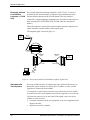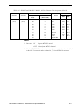
1
MEGAPLEX-2100 I/O Modules
Multi-Channel Low-Speed Data Modules
LS-2
LS-2A
LS-2A/2TS
MTLS-2
MTLS-2/2TS
LS-2/M
Installation and Operation Manual
Notice
This manual contains information that is proprietary to RAD Data Communications. No part of this publication may
be reproduced in any form whatsoever without prior written approval by RAD Data Communications.
No representation or warranties for fitness for any purpose other than what is specifically mentioned in this manual is
made either by RAD Data Communications or its agents.
RAD Data Communications reserves the right to revise this publication and make changes without obligation to
notify any person of such revisions or changes.
For further information contact RAD Data Communications at the address below or contact your local distributor.
RAD data communications
Headquarters
12 Hanechoshet Street
Tel Aviv 69710 Israel
Tel: 972-3-6458181
Fax: 972-3-6498250
E-mail: [email protected]
© 1999 RAD Data Communications
RAD data communications
US East
900 Corporate Drive
Mahwah, NJ 07430 USA
Tel: (201) 529-1100
Fax: (201) 529-5777
E-mail: [email protected]
RAD data communications
US West
3631 South Harbor Boulevard
Suite 250
Santa Ana, CA 92704
Tel: (714) 850-0555
Fax: (714) 850-1555
Publication No. 764-203-01/99
Table of Contents
Chapter 1.
Introduction
1.1 Functional Description ..............................................................................................................................1-1
General....................................................................................................................................................1-1
LS-2 Module Versions ............................................................................................................................1-2
Main Features..........................................................................................................................................1-3
MTLS-2 and LS-2A Modules............................................................................................................1-3
LS-2 Modules ....................................................................................................................................1-5
MTLS-2/2TS and LS-2A/2TS Modules ............................................................................................1-5
LS-2/M Module.................................................................................................................................1-6
Channel Characteristics...........................................................................................................................1-7
Channel Data Rates ...........................................................................................................................1-7
Digital Channel Transmission Modes................................................................................................1-7
Digital Channel Interfaces .................................................................................................................1-7
Digital Channel Connectors...............................................................................................................1-8
Digital Channel Timing Modes...............................................................................................................1-8
Timing in Synchronous Mode ...........................................................................................................1-8
Timing in Asynchronous Mode .........................................................................................................1-8
Characteristics of LS-2/M Channels .......................................................................................................1-9
Time Slot Routing...................................................................................................................................1-9
Management and Diagnostics ...............................................................................................................1-10
1.2 System Planning Considerations..............................................................................................................1-11
Byte Interleaved Multiplexing Formats.................................................................................................1-11
ITU-T Rec. X.50 Multiplexing Format ...........................................................................................1-11
ITU-T Rec. X.58 Multiplexing Format ...........................................................................................1-13
AT&T Pub. 54075 (DS0-B) Multiplexing Format ..........................................................................1-14
Example...........................................................................................................................................1-16
Module Groups .....................................................................................................................................1-17
Time Slot Routing Considerations ........................................................................................................1-17
1.3 Technical Specifications..........................................................................................................................1-18
Chapter 2.
Module Installation and Operation
2.1 General ......................................................................................................................................................2-1
2.2 Preparation for Installation ........................................................................................................................2-2
Modules MTLS-2 and MTLS-2/2TS ......................................................................................................2-2
Channel Interface Selection...............................................................................................................2-2
Channel Transmission Mode Selection, Switch S1 ...........................................................................2-3
Modules LS-2A and LS-2A/2TS.............................................................................................................2-4
2.3 Module Installation....................................................................................................................................2-6
Installation in Enclosure..........................................................................................................................2-6
Cable Connections ..................................................................................................................................2-6
Modules LS-2, LS-2A, LS-2A/2TS...................................................................................................2-6
Modules MTLS-2, MTLS-2/2TS ......................................................................................................2-6
Module LS-2/M.................................................................................................................................2-6
2.4 Module Panels ...........................................................................................................................................2-7
Modules MTLS-2, MTLS-2/2TS............................................................................................................2-7
Modules LS-2, LS-2A, LS-2A/2TS ........................................................................................................2-8
Module LS-2/M ......................................................................................................................................2-8
2.5 Normal Indications ....................................................................................................................................2-9
MP2100M-LS-2 Modules - Installation and Operation Manual
i
Modules LS-2, LS-2A, LS-2A/2TS, MTLS-2.........................................................................................2-9
Module MTLS-2/2TS .............................................................................................................................2-9
Module LS-2/M ......................................................................................................................................2-9
2.6 Configuration Instructions .......................................................................................................................2-10
General..................................................................................................................................................2-10
Internal Port (Module) Parameters ..................................................................................................2-10
External Port (Channel) Parameters ................................................................................................2-10
Time Slot Assignment...........................................................................................................................2-11
Chapter 3.
Alarms & Diagnostics
3.1 General ......................................................................................................................................................3-1
3.2 Alarm Messages ........................................................................................................................................3-1
3.3 Diagnostics ................................................................................................................................................3-3
Loopback Types......................................................................................................................................3-3
Local and Remote Main (Composite Channel) Loopback.................................................................3-3
Local Channel Loopback...................................................................................................................3-4
Remote Channel Loopback ...............................................................................................................3-4
External Modem Loopback (External Modem Remote Loop) - LS-2/M Only .......................................3-5
Externally Initiated Local Modem Loopback - LS-2/M Only .................................................................3-6
Recommended Test Sequence.................................................................................................................3-6
Appendix A. Connection Data
A.1 Interface Modules for MTLS-2/MTLS-2/2TS.........................................................................................A-1
A.2 LS-2/M Module Connectors ....................................................................................................................A-4
A.3 LS-2, LS-2A, and LS-2A/TS Modules Connectors .................................................................................A-5
ii
MP2100M-LS-2 Modules - Installation and Operation Manual
List of Figures
Figure 1-1. Typical Application for MTLS-2/X.50 Modules ...................................................... 1-3
Figure 1-2. Typical Application for MTLS-2/X.58 Modules ...................................................... 1-4
Figure 1-3. Typical Application for MTLS-2/SDM Modules...................................................... 1-4
Figure 1-4. Typical Application for MTLS-2/2TS and LS-2A/2TS Modules ............................. 1-5
Figure 1-5. Typical Application for LS-2/M Modules................................................................. 1-6
Figure 1-6. Typical Byte Interleaved TDM................................................................................ 1-11
Figure 1-7. ITU-T Rec. X.50 Envelope Structure...................................................................... 1-12
Figure 1-8. Repetitive Envelope Structure................................................................................. 1-12
Figure 1-9. Multiplexed Signal Structures................................................................................. 1-13
Figure 1-10. Structure of ITU-T Rec. X.58 Signal .................................................................... 1-14
Figure 2-1. MTLS-2 and MTLS-2/2TS Modules, Internal Settings ............................................ 2-3
Figure 2-2. DIP Switch S1 ........................................................................................................... 2-3
Figure 2-3. LS-2A and LS-2A/2TS Modules, Internal Settings .................................................. 2-5
Figure 2-4. Typical Module Panels.............................................................................................. 2-7
Figure 3-1. Local and Remote Main Loopback ........................................................................... 3-3
Figure 3-2. Local Channel Loop .................................................................................................. 3-4
Figure 3-3. Remote Channel Loop............................................................................................... 3-5
Figure 3-4. External Modem Loopback, Signal Path................................................................... 3-5
Figure 3-5. Externally Initiated Local Modem Loopback, Signal Path ....................................... 3-6
Figure A-1. IM-S68/2 and IMB-S68/2 Panels ............................................................................ A-1
MP2100M-LS-2 Modules - Installation and Operation Manual
iii
List of Tables
Table 1-1. Main Characteristics of LS-2 Module Versions ......................................................... 1-2
Table 1-2. ITU-T Rec. X.50 Equivalent Channels..................................................................... 1-12
Table 1-3. Frame Synchronization Sequence Length ................................................................ 1-15
Table 1-4. /SDM Version, Channel Availability for Highest User Rate of 19.2 kbps............... 1-15
Table 1-5. /SDM Version, Channel Availability for Highest User Rate of 9.6 kbps................ 1-16
Table 1-6. LS-2/SDM Channel Availability for Highest User Rate of 4.8 and 2.4 kbps........... 1-16
Table 2-1. Modules LS-2, LS-2A, LS-2A/2TS, Panel Components............................................ 2-8
Table 2-2. Module LS-2/M Panel Components ........................................................................... 2-8
Table 2-3. Internal Port Parameters ........................................................................................... 2-10
Table 2-4. External Port Parameters .......................................................................................... 2-11
Table 3-1. LS-2 Alarm Messages................................................................................................. 3-1
Table A-1. IM-S68/2 and IMB-S68/2 Modules, 68-Pin Connector Pin Assignment ................. A-2
Table A-2. LS-2/M Connector Pin Assignment.......................................................................... A-4
Table A-3. LS-2, LS-2A and LS-2A/TS Modules, 44-Pin Connector Pin Assignment ............. A-5
iv
MP2100M-LS-2 Modules - Installation and Operation Manual
Chapter 1.
Introduction
1.1 Functional Description
General
This manual describes the technical characteristics, applications, installation,
and operation of the LS-2 family of low-speed data sub-multiplexer modules for
the MEGAPLEX-2100 Modular T1/E1 Multiplexer Systems.
The LS-2 modules use byte-interleaved time division multiplexing to allow the
transmission of large numbers of low-speed synchronous and asynchronous
channels, at rates of 2.4, 4.8, 9.6, and 19.2 kbps, within one or two main link
time slots (64 kbps each). Modules with built-in modems, which enable direct
connection to remote data equipment connected through modems, are also
available.
The LS-2 modules are available in two physical sizes:
•
4U-high modules, designated LS-2, LS-2/M, LS-2A, and LS-2A/2TS, are
used in MEGAPLEX-2100/2104 chassis types. The user interface
connectors of these modules are located on the module panels.
•
6U-high modules, designated MTLS-2 and MTLS-2/2TS, are used in the
MEGAPLEX-2100B and MEGAPLEX-2100F chassis types. These
modules are interoperable with the corresponding 4U I/O modules.
The 6U modules do not include user interface connectors: instead, these
connectors are located on interface modules. The interface modules
intended for use in the MEGAPLEX-2100F chassis are designated
IM-S68/2, and the interface modules intended for use in the
MEGAPLEX-2100B chassis are designated IMB-S68/2.
To enable the user to use optimally the available payload capacity, all the LS-2
modules offer both automatic and manual envelope assignment.
Note
In this manual, the generic term LS-2 is used when the information is
applicable to all of the module versions, and the term MEGAPLEX is used
when the information is applicable to all of the multiplexer versions. The
complete designation is used only for information applicable to a specific
version.
MP2100M-LS-2 Modules - Installation and Operation Manual
1-1
Introduction
LS-2 Module
Versions
Table 1-1 lists the main characteristics of the various LS-2 module versions.
Table 1-1. Main Characteristics of LS-2 Module Versions
Version
Number of Transmission
Channels
Mode
Multiplexing
Standard
Main Link
Time Slots
Chassis Model, Module
Size, and Connectors
LS-2/X.50
10
Synchronous
only
ITU-T Rec. X.50
1
4U module for use in
MEGAPLEX-2100, and
LS-2.X.58
6
Synchronous
only
ITU-T X.58
1
MEGAPLEX-2104.
LS-2/SDM
10
Synchronous
only
AT&T Pub. 54075
1
Connectors: Two 44-pin D-type
female connectors for all
LS-2/M
6
Synchronous
only; built-in
modems
ITU-T Rec. X.50
1
modules, except LS-2/M, which
has six 6-pin RJ-11 connectors.
The connectors are located on
LS-2A/X.50
10
Synchronous &
asynchronous
ITU-T Rec. X.50
1
the rear panel of each module
LS-2A/X.58
6
Synchronous &
asynchronous
ITU-T Rec. X.58
1
LS-2A/SDM
10
Synchronous &
asynchronous
AT&T Pub. 54075
1
LS-2A/2TS
10
Synchronous &
asynchronous
ITU-T Rec. X.50
1 or 2
MTLS-2/X.50
10
Synchronous &
asynchronous
ITU-T Rec. X.50
1
MTLS-2/X.58
6
Synchronous &
asynchronous
ITU-T Rec. X.58
1
Connectors: Two 68-pin SCSI
MTLS-2/SDM
10
Synchronous &
asynchronous
AT&T Pub. 54075
MTLS-2A/2TS
10
Synchronous &
asynchronous
ITU-T Rec. X.50
1-2
6U module for use in the
MEGAPLEX-2100B and
MEGAPLEX-2100F.
1
female connectors, located on
an interface module
1 or 2
MP2100M-LS-2 Modules - Installation and Operation Manual
Introduction
Main Features
This section describes the main features of the modules offered in the LS-2 series.
MTLS-2 and LS-2A Modules
The MTLS-2 and LS-2A modules include three versions of modules, identified
by /X.50, /X.58, and /SDM. The MTLS-2 and LS-2A modules support both
synchronous and asynchronous operation.
MTLS-2/X.50,
LS-2A/X.50
These modules use a sub-multiplexing technique
compatible with ITU-T Rec. X.50, Division 3, and
ITU-T Rec. X.54. An MTLS-2/X.50 and LS-2A/X.50
module has ten channel interfaces; two modules can
be operated as one group to allow the transmission of
twenty channels in one main link time slot.
Since the maximum payload carried by a main link
time slot under the ITU-T Rec. X.50 Division 3
multiplexing format is 48 kbps, one /X.50 module can
provide ten 4.8 kbps channels, and a group of two
/X.50 modules can provide twenty 2.4 kbps channels.
Other combinations of channel numbers and data rates
are allowable within the specified payload, as
explained in Section 1.2.
Figure 1-1 shows a typical application for
MTLS-2/X.50 modules.
MEGAPLEX System
MEGAPLEX System
1
..
..
.. 20
1
..
. 10
1
MTLS-2
MTLS-2
MTLS-2
X.50
Cross Connect
Switch
MTLS-2
MTLS-2
MTLS-2
..
..
20 ..
1
..
10 .
Figure 1-1. Typical Application for MTLS-2/X.50 Modules
MTLS-2/X.58,
LS-2A/X.58
These modules use a sub-multiplexing technique
compatible with ITU-T Rec. X.58. An MTLS-2/X.58
or LS-2A/X.58 module has six channel interfaces. Up
to four modules can be operated as one group to allow
the transmission of up to 24 channels in one main link
time slot.
The maximum payload carried by a time slot under
the ITU-T Rec. X.58 multiplexing format is 57.6 kbps
(equivalent to 90% bandwidth efficiency). Therefore,
one /X.58 module can provide up to six 9.6 kbps
MP2100M-LS-2 Modules - Installation and Operation Manual
1-3
Introduction
channels, a group of two /X.58 modules can provide
up to twelve 4.8 kbps channels, and a group of four
/X.58 modules can provide up to twenty-four 2.4 kbps
channels. The allowable combinations of channel
numbers and data rates are explained in Section 1.2.
Figure 1-2 shows a typical application for
MTLS-2/X.58 modules.
MEGAPLEX System
MEGAPLEX System
1
12 x 4.8 kbps
(1 Time Slot)
6 x 9.6 kbps
(1 Time Slot)
.
.
.
.
. 12
.
1
..
. 6
1
MTLS-2
MTLS-2
MTLS-2
MTLS-2
X.58
Cross Connect
Switch
MTLS-2
MTLS-2
.
.
.
.
12 ..
1
..
6 .
Figure 1-2. Typical Application for MTLS-2/X.58 Modules
MTLS-2/SDM,
LS-2A/SDM
These modules use a sub-multiplexing technique
compatible with AT&T Pub. 54075 (DS0-B format).
This technique supports a maximum payload similar
to that specified by ITU-T Rec. X.50, Division 3, that
is 48 kbps.
Figure 1-3 shows a typical application for
MTLS-2/SDM modules.
20 x 2.4 kbps
(1 Time Slot)
Location 1
2.4 kbps
MEGAPLEX
System
1
..
. 10
..
. 20
.
.
.
.
.
.
MTLS-2
Location 20
2.4 kbps
MTLS-2
T1
1.544 Mbps
..
.
CPU
DDS
Network
City 1
9.6 kbps
1
5
MTLS-2
.
.
.
.
.
.
5 x 9.6 kbps
(1 Time Slot)
City 5
9.6 kbps
Figure 1-3. Typical Application for MTLS-2/SDM Modules
An MTLS-2/SDM or LS-2A/SDM module has ten
channel interfaces, and two modules can be operated as
one group to allow the transmission of twenty channels
in one main link time slot. One /SDM module can
provide up to ten 4.8 kbps channels, and a group of two
1-4
MP2100M-LS-2 Modules - Installation and Operation Manual
Introduction
/SDM modules can provide up to twenty 2.4 kbps
channels. Other combinations of channel numbers and
data rates are allowable (see Section 1.2).
LS-2 Modules
The LS-2 modules include three versions of modules, identified by /X.50,
/X.58, and /SDM. The LS-2 modules are similar in characteristics to the
MTLS-2 and LS-2A modules described above, except that they support only
synchronous operation.
MTLS-2/2TS and LS-2A/2TS Modules
Figure 1-4 shows a typical application for the MTLS-2/2TS and LS-2A/2TS
modules.
MEGAPLEX System
LS-2/2TS
.
.
.
.
.
1
10
Network
MEGAPLEX System
1
10
.
.
.
.
.
MTLS-2/2TS
Figure 1-4. Typical Application for MTLS-2/2TS and LS-2A/2TS Modules
The MTLS-2/2TS and LS-2A/2TS modules use a sub-multiplexing technique
compatible with ITU-T Rec. X.50, Division 3, and ITU-T Rec. X.54 to provide
two fixed functions:
•
Transmission of ten synchronous or asynchronous 9.6 kbps channels.
Channels 1 through 5 are transmitted as one group in one main link time
slot, and channels 6 through 10 are transmitted as one group in another
main link time slot.
MP2100M-LS-2 Modules - Installation and Operation Manual
1-5
Introduction
•
Transmission of five synchronous or asynchronous 9.6 kbps channels, in
one main link time slot.
LS-2/M Module
Figure 1-5 shows a typical application for the LS-2/M module.
MEGAPLEX System
1
12 x 2.4 kbps
(1 Time Slot)
6 x 4.8 kbps
(1 Time Slot)
..
..
.. 12
1
..
. 6
LS-2
LS-2
LS-2
X.50
Cross-Connect
Switch
1
LS-2/M
LS-2/M
12
1
LS-2/M
6
SRM-8
Modems
..
.
.
..
.
..
..
.
SRM-8
Modems
MEGAPLEX System
Figure 1-5. Typical Application for LS-2/M Modules
The LS-2/M module is a six-channel low-speed data sub-multiplexer with
built-in short range modems that uses a sub-multiplexing technique compatible
with ITU-T Rec. X.50, Division 3, and ITU-T Rec. X.54. Up four modules can
be operated as one group to allow the transmission of twenty 2.4 kbps channels
in one main link time slot. Since the maximum payload carried by a main link
time slot under the ITU-T Rec. X.50 Division 3 multiplexing format is 48 kbps,
the highest rate at which all six channels of one LS-2/M module can be utilized
is 4.8 kbps per channel; a group of two LS-2/M modules can be provide ten
4.8 kbps channels, and four modules can be provide twenty 2.4 kbps channels.
Other combinations of channel numbers and data rates are allowable within the
specified payload, as explained in Section 1.2.
The LS-2/M module provides an integrated solution for tail-end applications
that require providing full-duplex access to the MEGAPLEX link for remotely
located data equipment (LS-2/M modules cannot be operated in a link, they can
only operate in a link with /X.50 modules). The built-in modems are fully
compatible with the SRM-8 short-range modems offered by RAD.
1-6
MP2100M-LS-2 Modules - Installation and Operation Manual
Introduction
Channel Characteristics
Channel Data Rates
The channels of all the LS-2 module versions, except the /2TS versions, support
user-selectable data rates of 2.4, 4.8, 9.6 and 19.2 kbps; the /2TS versions
support only 9.6 kbps.
Digital Channel Transmission Modes
For all the module versions, the channels can operate in the synchronous mode.
For the LS-2A, LS-2A/2TS, MTLS-2 and MTLS-2/2TS versions, channels can
also operate in the asynchronous mode.
With respect to mode selection (synchronous/asynchronous), the channels are
divided into three groups:
•
For /X.50 and /SDM versions: channel 1, channels 2 through 5, and
channels 6 through 10.
•
For /X.58 versions: channel 1, channels 2 and 3, and channels 4, 5, and 6.
For each group, the user can select the desired transmission mode, using an
internal DIP switch.
Digital Channel Interfaces
All the channels, except the channels of the LS-2/M module, which are
equipped with built-in modems, have V.24/RS-232 interfaces. The
V.24/RS-232 interface type is user-selectable (DCE or DTE). The method used
to select the interface type varies with the module version:
•
For the MTLS-2 and MTLS-2/2TS versions, the selection is made by means
of jumpers.
•
For the LS-2, LS-2A, and LS-2A/2TS versions, the selection is made by
using the appropriate adapter cables.
Each channel interface locally supports the following control signals: RTS,
CTS, DSR, DTR, and DCD. The functions of these lines depends on the
interface operation mode:
•
For DCE interfaces, the lines are used as follows:
The local CTS line is an output, and either follows the state of the RTS
line (which is an input) after a selectable delay (minimum or 50 msec),
or can be set to be always ON.
The DSR line is an output, and is continuously ON.
The DTR line is an input, but is ignored (assumed to be asserted at all
times).
The DCD line is an output, and its state is selectable: continuously ON,
or ON only when the LS-2 module is synchronized.
The selections are made by software configuration.
MP2100M-LS-2 Modules - Installation and Operation Manual
1-7
Introduction
•
For DTE interfaces, the lines are used as follows:
The RTS line is an output, and the CTS line is an input (this input is
ignored, i.e., assumed to be asserted at all times).
The DSR and DCD lines are inputs.
The DTR line is an output, and is continuously ON.
Digital Channel Connectors
With respect to connectors, the digital channels are divided into two groups of
equal size. For ten-channel modules, the groups include the channels 1 through
5, and 6 through 10, respectively, whereas for six-channel modules, the groups
include the channels 1 through 3, and 4 through 6, respectively. Each group has
a separate connector.
•
For the 4U-high modules, the connectors (44-pin female D-type connectors)
are located on the module panel itself. An adapter cable may be ordered to
separately connect each of the channels available in one connector to
individual user's equipment. Each cable terminates in five 25-pin D-type
connectors.
•
For the 6U-high modules, the connectors (68-pin female SCSI connectors)
are located on interface modules.
Digital Channel Timing Modes
Timing in Synchronous Mode
When using the synchronous mode, each digital channel has three
user-selectable timing modes:
•
DCE: the channel provides the transmit and receive clock signals to the
DTE connected to the channel. This mode can be used only when the DCE
interface is selected.
•
External DCE (also called DTE1): the channel provides the receive clock
signal, and accepts the transmit clock signal from the equipment connected
to the channel (tail-end circuit). This mode can be used only when the DTE
interface is selected.
•
DTE (also called DTE2): the channel uses the clock signals provided by
the DCE equipment connected to the channel for both its receive and
transmit paths, and buffers and retimes the incoming data. In this mode, the
receive and transmit timing is the same. This mode can be used only when
the DTE interface is selected.
Timing in Asynchronous Mode
LS-2A, LS-2A/2TS, MTLS-2 and MTLS-2/2TS channels can be operated in the
asynchronous mode by activating synchronous-to-asynchronous converters,
using an internal DIP switch. The converters can be independently
enabled/disabled for each channel group, as explained above.
1-8
MP2100M-LS-2 Modules - Installation and Operation Manual
Introduction
Because of the use of synchronous-to-asynchronous conversion, when
configuring the individual channels, it is necessary to select the DCE timing
mode for asynchronous channels.
In the asynchronous mode, the user can select the word length (8 through
11 bits) using an internal DIP switch. The required word length is obtained the
adding the number of start bits, data bits, parity bits, and stop bits generated by
the user's asynchronous equipment. The bits are transparently transferred, e.g.,
when parity is used, no parity check is made by the channel.
The word length can be independently selected for each channel group, as
explained above.
Characteristics of
LS-2/M Channels
The LS-2/M channels have built-in modems, which are intended for operation
over unconditioned 4-wire telephone loops (two twisted pairs). Typical ranges
are as follows:
•
At the highest channel data rate, 19.2 kbps, typical ranges are up to 10 km
(6.25 miles) over AWG 19 (0.9 mm) pairs, up to 4.5 km (2.8 miles) over
AWG 24 (0.5 mm) pairs, and up to 3.0 km (1.8 miles) over AWG 26
(0.4 mm) pairs.
•
At 2.4 kbps, typical ranges are up to 15 km (9.3 miles) over AWG 19
(0.9 mm) pairs, up to 6.5 km (4.0 miles) over AWG 24 (0.5 mm) pairs, and
up to 5 km (3.1 miles) over AWG 26 (0.4 mm) pairs.
Each of the LS-2/M channels provides the receive timing signal to the built-in
short-range modem, and accepts a transmit clock from the modem (this timing
mode is similar to the DTE1 mode). Therefore, the LS-2/M channel determines
the timing of the data sent to the external modem.
To ensure that the same timing is used on the transmit direction (from the
external modem to the LS-2/M channel), the external modem must operate with
loopback timing. The transmit clock is recovered by the built-in modem from
the line signal received from the external SRM-8 modem.
Time Slot Routing
The MEGAPLEX system enables the user to select the main link that will carry
the data applied to the LS-2 module or module group (when LS-2 module
groups are used, the selected routing applies to all the modules included in the
group). Moreover, the user can select, for each LS-2 module or module group,
the main link time slots assigned in the corresponding T1 or E1 main link frame.
User-controlled manual assignment allows the routing of the bit stream
generated by each local module or module group to another compatible LS-2
module, respectively module group.
The LS-2/M module can also operate in a link with the MTLS-2/X.50,
LS-2A/X.50, and LS-2/X.50 ten-channel data module, provided compatible
envelope assignment is used.
MP2100M-LS-2 Modules - Installation and Operation Manual
1-9
Introduction
Management and
Diagnostics
Channel data rates, as well as all the operating parameters are controlled by the
system management.
Self-diagnostics upon power-up, as well as powerful testing capabilities
controlled by the system management, reduce downtime to a minimum.
The diagnostics functions available on the LS-2 modules are as follows:
•
Activation of a local or remote test loopback on the desired module
channel. The module also supports local and remote digital loopbacks on
the module composite (internal port 1 of the MEGAPLEX system) data
stream, activated by commands from system management.
•
For the LS-2/M module only: external modem loopback similar to ITU-T
Rec. V.54 loop 2, activated on the external modem by commands from
system management, and local loopback activated on the internal channel
modem upon request of the external modem.
For convenience, the MEGAPLEX system enables the user to specify the time a
loopback remains active: the range is 1 through 30 minutes, in 1-minute steps.
After the specified time, the loopback is automatically deactivated by the
module, thereby reducing the management workload during system
troubleshooting. The default selection is continuous connection, that is, the
loopback remain active until canceled by a user's command.
In addition to the loopbacks listed above, the module panels includes indicators
for the synchronization status of the module, and for the LS-2/M module, CD
(carrier detect) and test indicators for each channel.
1-10
MP2100M-LS-2 Modules - Installation and Operation Manual
Introduction
1.2 System Planning Considerations
This section explains the multiplexing formats used by the different LS-2
models, and provides information regarding the number of channels versus
channel data, and information on LS-2 time slot routing.
Byte Interleaved
Multiplexing
Formats
The LS-2 modules perform byte-interleaved time division multiplexing (TDM).
In byte-interleaved TDM, the information received from each module is inserted
in an eight-bit envelope. The envelopes received from the various channels are
then sequentially transmitted via the main link. The byte interleaving technique
for the particular case of all channels operating at the same rate is illustrated in
figure 1-6.
CH 1
CH 2
.
.
.
.
.
.
Byte
Multiplexer
Byte-Interleaved Multiplexed
Data Stream
CH N
Byte 1 CH 1 Byte 1 CH 2 . . . . . .
. . . .2.CH 2 . . . . . .
Byte 1 CH N Byte 2 CH 1 .Byte
Byte 2 CH N Byte 3 CH 1
.....
8-Bit
Envelope
Figure 1-6. Typical Byte Interleaved TDM
The sub-multiplexing techniques specified by ITU-T Rec. X.50, ITU-T Rec.
X.58 and AT&T Pub. 54075 define the organization of data in the multiplexed
frame, and thus determine the number of channels (and their data rates) that can
be carried in the allocated main link bandwidth, which is always 64 kbps.
ITU-T Rec. X.50 Multiplexing Format
The ITU-T Rec. X.50, Division 3 format is based on the envelope structure
shown in figure 1-7. The envelope consists of one frame synchronization bit,
designated F bit, 6 user data bits, and one S (status) bit. Therefore the
multiplexing overhead is 25%, and the maximum user payload carried by a time
slot multiplexed in accordance with ITU-T Rec. X.50, Division 3, i.e., the sum
of the data rates of all the user's channels connected to a /X.50 module, is
48 kbps.
To understand this limitation, it is necessary to understand the structure of a
ITU-T Rec. X.50 submultiplexed signal. ITU-T Rec. X.50 divides the available
transmission bandwidth, 64 kbps, into equivalent channels, in accordance with
a structure that was originally designed for a maximum user channel data rate
of 9.6 kbps (it can however be extended to 19.2 kbps as explained below).
MP2100M-LS-2 Modules - Installation and Operation Manual
1-11
Introduction
Envelope
1
2
3
4
5
6
6 User Data
Bits
F Bit
(Framing and
Housekeeping)
7
8
S Bit
(Status Bit)
Figure 1-7. ITU-T Rec. X.50 Envelope Structure
The resulting equivalent channels are listed in Table 1-2. Note that the user's
payload is 6/8th of the equivalent channel rate.
Table 1-2. ITU-T Rec. X.50 Equivalent Channels
Channel Rate
Number of Channels in 64 kbps
User's Payload
12.8 kbps
5
9.6 kbps
6.4 kbps
10
4.8 kbps
3.2 kbps
20
2.4 kbps
Referring to the byte-interleaved structure of figure 1-6, it is seen that a user's
channel of 9.6 kbps will repeat in every 5th envelope, a 4.8 kbps channel will
repeat in every 10th envelope, and a 2.4 kbps will repeat in every 20th
envelope. It is therefore convenient to view an ITU-T Rec. X.50
byte-interleaved multiplexer as a multiplexer that uses a repetitive structure
consisting of 20 envelopes, as shown in figure 1-8. The smallest repetitive
substructure is then of 5 envelopes. Note however that the frame
synchronization sequence remains unchanged and it repeats every 20 frames.
Repetitive Envelope Structure
Basic
Substructure
Envelope No. 1
2
3
4
5
6
7
8
9 10 11 12 13 14 15 16 17 18 19 20 1
.....
2 .....
Figure 1-8. Repetitive Envelope Structure
Figure 1-9 shows the structure of a multiplexed signal that uses the 20-envelope
multiplexing model.
1-12
MP2100M-LS-2 Modules - Installation and Operation Manual
Introduction
Envelope No.
1 7 2 8 3 9 4105116127138149151016111712181319142015 16 17 18 19 20 1
2
3
4
5
6
7
8
9 10 11 12 13 14 15 16 17 18 19 20 1
...
2.4 kbps
Channel
(1 Envelope
Out of 20)
1 7 2 8 3 9 4105116127138149151016111712181319142015 16 17 18 19 20 1
2
3
4
5
6
7
8
9 10 11 12 13 14 15 16 17 18 19 20 1
...
4.8 kbps
Channel
(2 Envelopes
Out of 20)
1 7 2 8 3 9 4105116127138149151016111712181319142015 16 17 18 19 20 1
2
3
4
5
6
7
8
9 10 11 12 13 14 15 16 17 18 19 20 1
...
9.6 kbps
Channel
(4 Envelopes
Out of 20)
1 7 2 8 3 9 4105116127138149151016111712181319142015 16 17 18 19 20 1
2
3
4
5
6
7
8
9 10 11 12 13 14 15 16 17 18 19 20 1
...
19.2 kbps
Channel
(8 Envelopes
Out of 20)
1 7 2 8 3 9 4105116127138149151016111712181319142015 16 17 18 19 20 1
2
3
4
5
6
7
8
9 10 11 12 13 14 15 16 17 18 19 20 1
...
Figure 1-9. Multiplexed Signal Structures
In accordance with the byte-interleaved multiplexing principles:
•
A 2.4 kbps user channel uses one envelope out of every 20, and thus
appears once per structure.
•
A 4.8 kbps user channel uses two envelopes out of every 20, and thus
appears twice per structure.
•
A 9.6 kbps user channel uses four envelopes out of every 20, and thus
appears four times per structure.
•
A 19.2 kbps user channel uses eight envelopes out of every 20, and thus
appears eight times per structure. Note that the envelopes are assigned in
pairs.
Note that a /2TS module can handle two independent byte-interleaved
multiplexing structures.
ITU-T Rec. X.58 Multiplexing Format
The multiplexing format specified by ITU-T Rec. X.58 based on a repetitive
structure of 80 envelopes, organized in four substructures of 20 envelopes. In
each substructure, two envelopes are assigned to framing and housekeeping.
The remaining 18 envelopes carry only user data. Therefore this multiplexing
format has a bandwidth efficiency of 90%, for a maximum user payload of
57.6 kbps, i.e., the sum of the data rates of all the user's channels connected to
the LS-2/X.58 must not exceed 57.6 kbps.
Figure 1-10 shows the structure of the ITU-T Rec. X.58 signal. To facilitate the
understanding of the signal structure, the envelopes assigned to user data are
identified by letters A through F, followed by a numeral.
MP2100M-LS-2 Modules - Installation and Operation Manual
1-13
Introduction
Substructure No.1
S1
1
2
3
4
5
6
7
8
9
10
11
12
13
14
15
16
17
A1
B1
C1
D1
E1
F1
B2
A2
D2
C2
F2
E2
A3
B3
C3
D3
E3
F3
20
21
22
23
24
25
26
27
28
29
30
31
32
33
34
35
36
B4
A4
D4
C4
F4
E4
A1
B1
C1
D1
E1
F1
B2
A2
D2
C2
F2
E2
18
Substructure No.2
S2
19
Substructure No.3
S3
37
38
39
40
41
42
43
44
45
46
47
48
49
50
51
52
53
54
A3
B3
C3
D3
E3
F3
B4
A4
D4
C4
F4
E4
A1
B1
C1
D1
E1
F1
Substructure No.4
S4
55
56
57
58
59
60
61
62
63
64
65
66
67
68
69
70
71
72
B2
A2
D2
C2
F2
E2
A3
B3
C3
D3
E3
F3
B4
A4
D4
C4
F4
E4
T1
T2
T3
T4
LEGEND
S - Framing Byte
T - Housekeeping Byte
Figure 1-10. Structure of ITU-T Rec. X.58 Signal
The user envelopes are assigned as follows:
•
A 2.4 kbps user channel uses three envelopes out of every 80, and thus
appears three times per structure (the envelopes identified by the same
letter/numeral combination, e.g., one 2.4 kbps channel in all the A1
envelopes, another in all the B1 envelopes, etc.). Therefore, the maximum
number of 2.4 kbps channels that can be carried by one main link time slot
is twenty-four: this requires a group of four LS-2/X.58 modules.
•
A 4.8 kbps user channel uses six envelopes out of every 80, and thus
appears six times per structure (the envelopes identified by the same letter,
and an odd or even numeral, e.g., one 4.8 kbps channel in all the A1+A3
envelopes, another in all the A2+A4 envelopes, etc.). Therefore, the
maximum number of 4.8 kbps channels that can be carried by one main link
time slot is twelve: this requires a group of two LS-2/X.58 modules.
•
A 9.6 kbps user channel uses twelve envelopes out of every 80, and thus
appears twelve times per structure(the envelopes identified by the same
letter, e.g., one 9.6 kbps channel in all the A envelopes, another in all the B
envelopes, etc.). Therefore, the maximum number of 9.6 kbps channels that
can be carried by one main link time slot is six.
•
A 19.2 kbps user channel uses twenty-four envelopes out of every 80, and
thus appears twenty-four times per structure, i.e., at twice the rate of the
9.6 kbps channels, by using envelopes pairs (A and D, B and E, or C and F).
Therefore, the maximum number of 19.2 kbps channels that can be carried by
one main link time slot is three.
AT&T Pub. 54075 (DS0-B) Multiplexing Format
The multiplexing format specified by AT&T Pub. 54075 is similar to the
multiplexing format of ITU-T Rec. X.50. Therefore, the multiplexing format
presented in figures 1-7 and 1-9 also defines the multiplexing capabilities of an
LS-2/X.50 module.
The main differences are as follows:
•
1-14
Referring to figure 1-7, the eighth bit in each byte serves as a network
MP2100M-LS-2 Modules - Installation and Operation Manual
Introduction
control bit, which indicates the information carried by each byte:
0
1
•
Control data
User data
The first bit is used exclusively as a framing bit. The length of the frame
synchronization sequence depends on the highest required channel data rate
as shown in Table 1-3.
Table 1-3. Frame Synchronization Sequence Length
Highest Channel Data Rate
Frame Synchronization Sequence Length
2.4 kbps
20 bits
4.8 kbps
10 bits
9.6 kbps
5 bits
19.2 kbps
5 bits
Since the number of bytes contained in the repetitive frame structure depends
on the length of the frame synchronization sequence, the multiplexing
capabilities are determined by the highest user data rate that must be carried.
The combinations that achieve maximal utilization of the available bandwidth
are detailed in Tables 1-4, 1-5 and 1-6.
Table 1-4. /SDM Version, Channel Availability for Highest User Rate of
19.2 kbps
Number of User Channels vs. Data Rate
Number of Envelopes
in Structure
19.2 kbps
9.6 kbps
4.8 kbps
2.4 kbps
5
2
1
–
–
2
–
1
–
2
–
–
1
1
3
–
–
1
2
1
–
1
2
–
1
1
1
2
–
1
1
1
1
1
1
–
2
1
–
3
–
1
–
2
1
1
–
1
2
1
–
–
3
MP2100M-LS-2 Modules - Installation and Operation Manual
1-15
Introduction
Table 1-5. /SDM Version, Channel Availability for Highest User Rate of
9.6 kbps
Number of Envelopes
Number of User Channels vs. Data Rate
in Structure
9.6 kbps
4.8 kbps
2.4 kbps
5
5
4
4
3
3
3
2
2
2
2
1
1
1
1
1
–
1
–
2
1
–
3
2
1
–
4
3
2
1
–
–
–
1
–
1
2
–
1
2
3
–
1
2
3
4
Table 1-6. LS-2/SDM Channel Availability for Highest User Rate of 4.8 and
2.4 kbps
Number of User Channels
vs. Data Rate
Highest User
Number of Envelopes
Rate
in Structure
4.8 kbps
2.4 kbps
4.8 kbps
10
1
2
3
4
5
6
7
8
9
10
9
8
7
6
5
4
3
2
1
–
2.4 kbps
20 (requires group of two
LS-2/SDM modules)
–
20
Example
If the highest data rate of any user channel connected to a /SDM module is
9.6 kbps, and you have to transfer two 9.6 kbps channels, then Table 1-5
shows that you can also transfer three 4.8 kbps channels, or two 4.8 kbps
channels and one 2.4 kbps channel, or one 4.8 kbps and two 2.4 kbps
channels, or three 2.4 kbps channels.
Note that you can always use less channels than the maximum specified by
the table.
1-16
MP2100M-LS-2 Modules - Installation and Operation Manual
Introduction
Module Groups
To allow the utilization of the maximal number of channels that can be carried
in one time slot, the LS-2 modules can be operated in groups. A group is formed
by assigning the desired group ID number to all the LS-2 modules that will be
part of the group (the assignment is performed by means of the system
management). The available range of group numbers is 1 through 12.
A group can consist of:
•
One or two /X.50 modules.
•
One or two /SDM modules.
•
One, two, three or four /X.58 modules.
Each LS-2 module in a group must be assigned a group member number. The
range of available group member numbers is 1 through 4 (the assignment is
performed by means of the system management). The member must be unique
in a given group.
Note
Each LS-2 module installed in a MEGAPLEX enclosure must be assigned a
unique combination of group number and group member number. Therefore, if
each LS-2 module operates alone, assign the slot number as a group number.
The use of this numbering scheme allows the MEGAPLEX to multiplex the
information from LS-2 modules installed in the enclosure in accordance with
the group numbers (irrespective of the physical position of each module), and
insert the multiplexed information of each group into one main link time slot.
Time Slot Routing
Considerations
The time slot assigned to LS-2 modules is assigned on the basis of their group
ID number, i.e., each group occupies one time slot, irrespective of the number of
modules in the group. However, fully-utilized /2TS modules (carrying ten
9.6 kbps channels) require two time slots.
The assigned time slot can be routed to another group of LS-2 modules in the
remote MEGAPLEX unit), or to a high-speed module such as the MTHS-Q.
MP2100M-LS-2 Modules - Installation and Operation Manual
1-17
Introduction
1.3 Technical Specifications
Module Characteristics
See Table 1-1
Time Slots Used
One time slot per group (64 kbps main link bandwidth).
Results in the following number of channels:
Data Rate /X.50, /SDM Versions
/2TS Versions
/X.58 Version
2.4 kbps
20
10
24
4.8 kbps
10
10
12
9.6 kbps
5
10
6
19.2 kbps
2 (plus one 9.6 kbps)
4 (plus two 9.6 kbps)
3
Digital Channel Interface Type
V.24/RS-232, DTE or DCE (user-selectable)
Bit rates
2.4, 4.8, 9.6 or 19.2 kbps
Channel transmission mode
Synchronous or asynchronous; independently-selectable in
the following groups:
−
/X.50 and /SDM: channel 1, channels 2 through 5, and 6
through 10
−
/X.58: channel 1, channel 2, 3, and channels 4, 5, 6
Synchronous channel clocking
DCE, external DCE or DTE, user-selectable per channel
Asynchronous word length
8 through 11 bits, independently-selectable in the following
groups:
Channel control signals
−
−
−
/X.50 and /SDM: channels 1 through 5, and 6 through 10
−
−
DSR: constantly ON
/X.58: channels 1, 2, 3 and channels 4, 5, 6
Selectable RTS to CTS delay: constantly ON, minimum
delay (up to 20 msec), or 50 msec
DCD: ON when synchronized, or constantly ON
(programmable)
LS-2/M Channel Modem Characteristics
Line type
4-wire unconditioned telephone loops
Transmit level
-6 dBm
Typical range
Data Rate AWG 19 (0.9 mm) AWG 24 (0.5 mm) AWG 26 (0.4 mm)
1-18
2.4 kbps
15.0 km
6.5 km
5.0 km
4.8 kbps
14.0 km
6.0 km
4.5 km
9.6 kbps
12.0 km
5.5 km
4.0 km
19.2 kbps
10.0 km
4.5 km
3.0 km
MP2100M-LS-2 Modules - Installation and Operation Manual
Introduction
Modem bit rates
2.4, 4.8, 9.6 or 19.2 kbps, synchronous
Modem clocking
DTE1 (transmit clock from built-in modem and receive
clock to built-in modem)
Connectors
Diagnostic Tests
See Table 1-1
−
−
−
−
Local and remote module loopback
−
CD (green, one for each sub-channel): lights when a valid
signal is received from the remote modem
−
TST (red, one for each sub-channel): lights when a
modem loopback is active
Local channel loopback
Remote channel loopback
Local loopback upon command from external modem
Indicators
LS-2/M channels
All other modules
Configuration
Local sync loss indicators, for indication of module
synchronization status
Programmable via system management
MP2100M-LS-2 Modules - Installation and Operation Manual
1-19
Introduction
1-20
MP2100M-LS-2 Modules - Installation and Operation Manual
Chapter 2.
Module Installation and
Operation
2.1 General
This chapter provides installation, configuration and operation instructions for
the various versions of LS-2 modules. The information presented in this chapter
supplements the general MEGAPLEX-2100 installation, configuration and
operation instructions contained in Part I of the Installation and Operation
Manual.
Warning
Before performing any internal settings, adjustment, maintenance, or
repairs, first disconnect all the cables from the module, and then remove
the module from the MEGAPLEX enclosure.
No internal settings, adjustment, maintenance, and repairs may be
performed by either the operator or the user; such activities may be
performed only by a skilled technician who is aware of the hazards
involved.
Always observe standard safety precautions during installation, operation,
and maintenance of this product.
Caution
The LS-2 modules contain components sensitive to electrostatic discharge
(ESD). To prevent ESD damage, always hold modules by their sides, and do not
touch the module components or connectors.
MP2100M-LS-2 Modules - Installation and Operation Manual
2-1
Module Installation and Operation
2.2 Preparation for Installation
The operating mode of the LS-2 and LS-2/M module versions is controlled only
by software, and therefore no jumpers or switches have to be set by the user.
Therefore, for these modules you may skip this section and proceed with the
installation of the module in the equipment enclosure, as explained in
Section 2.3.
For the other module versions, there are hardware settings that control
parameters which are not configurable by software. The hardware settings are
as follows:
•
For the LS-2A, LS-2A/2TS, MTLS-2A, and MTLS-2A/2TS modules, it is
necessary to select the transmission mode (synchronous/asynchronous) of
the channels. For channels operating in the asynchronous mode, it is
necessary to select the word frame format.
•
For the MTLS-2A and MTLS-2A/2TS, it is also necessary to select the
interface type, DCE or DTE, for each channel.
The following sections provides detailed instructions for making the required
settings for each type of module.
Modules MTLS-2
and MTLS-2/2TS
Figure 2-1 identifies the location of the jumpers and switches located on the
MTLS-2 and MTLS-2/2TS modules.
Channel Interface Selection
The module has several groups of DCE-DTE interface selection jumpers (one
group for each channel). The channel served by each group is marked on the
board. The channel interface selection jumpers can be independently set for
each channel, in accordance with the desired interface type:
DCE
Select this setting when connected to a DTE. In this
case, configure the channel for DCE timing.
DTE
Select this setting in the following applications:
• When connected directly to a DCE. In this case,
configure the channel for DTE timing (DTE2).
• When connected to a DCE in a tail-end circuit. In
this case, configure the channel for external DCE
(DTE1) timing.
Always move all the jumpers of one group to the same position.
2-2
MP2100M-LS-2 Modules - Installation and Operation Manual
Module Installation and Operation
DCE
DTE
DCE
CH6-10
CH1-5
DCE
LENGTH
8BI
T
9BI
T
10BI
CH1
CH2-5
CH6-10
LEN0
LEN1
LEN0
LEN1
OFFASYNC
ON-SYNC
DTE
S1
1
2
3
4
5
6
7
8
T
11BI
T
LEN1
OF
F
OF
F
O
N
O
N
DTE
LEN0
OF
F
O
N
OF
F
O
N
DCE
DTE
DCE-DTE
SELECTORS
DCE
DTE
DCE
DC
E
MOD
E
DT
E
MOD
E
DTE
DCE
DTE
DCE
DTE
DCE
DTE
DCE
DTE
DCE
DTE
CH6
CH7
CH8
CH9
CH10
CH1
CH2
CH3
CH4
CH5
Figure 2-1. MTLS-2 and MTLS-2/2TS Modules, Internal Settings
Channel Transmission Mode Selection, Switch S1
CH1
OFF-ASYNC
CH2-5
ON-SYNC
CH6-10
LEN0
CH1-5
LEN1
LEN0
CH6-10
LEN1
Figure 2-2 shows the DIP switch S1, and identifies the functions of its sections.
ON
S1
1
2
3
4
5
6
7
8
LENGTH
LEN1
LEN0
8BIT
9BIT
10BIT
11BIT
OFF
OFF
ON
ON
OFF
ON
OFF
ON
Figure 2-2. DIP Switch S1
MP2100M-LS-2 Modules - Installation and Operation Manual
2-3
Module Installation and Operation
Sections 1, 2, 3
These sections select the channel transmission mode
(synchronous or asynchronous). With respect to the
transmission mode (synchronous or asynchronous),
the channels are divided into three groups.
• Section 1: controls channel 1.
• Section 2: for /X.50 and /SDM versions, controls
channels 2 through 5, and for /X.58 versions controls channels 2 and 3.
• Section 3: for /X.50 and /SDM versions, controls
channels 6 through 10, and for /X.58 versions controls channels 4, 5, and 6.
For each group, select the desired transmission mode
by setting the corresponding section to OFF for
asynchronous operation, or to ON for synchronous
operation.
Modules LS-2A
and LS-2A/2TS
Sections 4, 5
These sections select the word length (8 through 11
bits) used by channels 1 through 5 (for /X.58 versions
- by channels 1, 2, 3) when configured for operation
in the asynchronous mode. The required word length
is obtained by adding the number of start bits, data
bits, parity bits, and stop bits generated by the user's
asynchronous equipment. The settings required for
each word length are identified in figure 2-2.
Sections 6, 7
These sections select the word length (8 through 11
bits) used by channels 6 through 10 (for /X.58
versions - by channels 4, 5, 6) when operating in the
asynchronous mode.
Section 8
Reserved for future use. Set to OFF.
Modules LS-2A and LS-2A/2TS have one switch, designated S1, which is used
to select the transmission mode of the channels. The switch is located on a
daughter board, and is accessible from the top of the board.
Figure 2-3 identifies the location of the switch, and the functions of its sections.
The switch is identical to the switch S1 located on the MTLS-2 and
MTLS-2/2TS modules, explained in the previous section.
2-4
MP2100M-LS-2 Modules - Installation and Operation Manual
Module Installation and Operation
OFF
ON
OFF
ON
OFF
OFF
ON
ON
LEN1 LEN0
LENGTH
8BIT
9BIT
10BIT
11BIT
OFF-ASYNC CH1
ON-SYNC CH2-5
CH6-10
LEN0
CH1-5
LEN1
LEN0
CH6-10
LEN1
S1
ON
1
2
3
4
5
6
7
8
ON
S1
2
3
4
5
6
7
OFF-ASYNC CH1
ON-SYNC CH2-5
CH6-10
LEN0
CH1-5
LEN1
LEN0
CH6-10
LEN1
1
8
LENGTH
8BIT
9BIT
10BIT
11BIT
LEN1 LEN0
OFF
OFF
ON
ON
OFF
ON
OFF
ON
Figure 2-3. LS-2A and LS-2A/2TS Modules, Internal Settings
MP2100M-LS-2 Modules - Installation and Operation Manual
2-5
Module Installation and Operation
2.3 Module Installation
For your safety, do not connect cables to the module before the module is
installed in a properly installed and grounded MEGAPLEX enclosure.
Installation in
Enclosure
Refer to the system installation plan and insert the module in the assigned I/O
slot of the MEGAPLEX enclosure.
For MTLS-2 and MTLS-2/2TS modules, install the required interface module
in the corresponding slot:
Cable Connections
•
IM-S68/2 interface module for the MEGAPLEX-2100F.
•
IMB-S68/2 interface module for the MEGAPLEX-2100B.
Identify the cables intended for connection to the module, and connect the
cables to the appropriate connectors.
Modules LS-2, LS-2A, LS-2A/2TS
•
If the module channels connect to a main distribution frame, connect
appropriate cables to the 44-pin module connector. Refer to Appendix A for
connector pin assignments.
•
If the channels connect directly to equipment, connect an octopus cable to
each 44-pin module connector. Connect each 25-pin connector, in
accordance with the marking near the cable end, to the user's equipment.
If the user equipment connected to a channel has a DTE interface,
connect the user equipment via a standard straight cable to the
corresponding connector of the octopus cable.
If the user equipment connected to a channel has a DCE interface, a
short (30 cm, 1 foot) cross cable must be connected at the
corresponding user-end connector of the octopus cable. Connect the
user equipment via a standard straight cable to the corresponding
connector of the cross cable.
Modules MTLS-2, MTLS-2/2TS
•
If the module channels connect to a main distribution frame, connect
appropriate cables to the 68-pin connectors of the corresponding interface
module. Refer to Appendix A for connector pin assignments.
•
If the channels connect directly to equipment, connect an CBL-LS202
octopus cable to each connector. Connect each 25-pin connector, in
accordance with the marking near the cable end, to the user's equipment.
Module LS-2/M
Connect the line cables to the corresponding RJ-11 connector.
2-6
MP2100M-LS-2 Modules - Installation and Operation Manual
Module Installation and Operation
2.4 Module Panels
The panels of the LS-2 modules are shown in figure 2-4.
MTLS-2
TS-A
TS-B
SYNC LOSS
LS-2/M
LS-2/A
SYNC LOSS
SYNC-LOSS
TST
CH 1-5
CD
CH-1
TST
CD
CH-2
TST
CD
CH-3
TST
CH 6-10
CD
CH-4
TST
CD
CH-5
TST
CD
CH-6
Figure 2-4. Typical Module Panels
Modules MTLS-2,
MTLS-2/2TS
The MTLS-2 and MTLS-2/2TS panels include two SYNC LOSS indicators.
•
For the MTLS-2 module, only the SYNC LOSS TS-A indicator is in use,
and lights when the local MTLS-2 module loses synchronization to the
remote MTLS-2 module. The indicator designated SYNC LOSS TS-B is
always off.
•
For the MTLS-2/2TS module, the SYNC LOSS TS-A indicator lights when
MP2100M-LS-2 Modules - Installation and Operation Manual
2-7
Module Installation and Operation
the first group of channels (1 through 5) of the local module, which uses
one time slot, loses synchronization to the corresponding group of the
remote module. The indicator designated SYNC LOSS TS-B has the same
function with respect to the second group of channels (6 through 10), which
uses the other time slot; the indicator is off when only the first group of
channels is in use.
The MTLS-2 and MTLS-2/2TS modules do not have channel connectors, as
these connectors are located on the interface module, IM-S68/2 or IMB-568/2,
described in Appendix A-1.
Modules LS-2,
LS-2A, LS-2A/2TS
Table 2-1 describes the functions of the LS-2, LS-2A and LS-2A/2TS panel
components.
Table 2-1. Modules LS-2, LS-2A, LS-2A/2TS, Panel Components
Item
Description
SYNC LOSS
Lights when the local module is not synchronized to the remote module. For the LS-2A/2TS,
both channel groups must be synchronized for the indicator to turn off
CH1-5 Connector
44-pin connector for connection to channels 1 through 5 of the module (for /X.58 version channels 1 through 3). Connector pin assignments and functions are given in Appendix A
CH6-10 Connector 44-pin connector for connection to channels 6 through 10 of the module (for /X.58 version channels 4 through 6). Connector pin assignments and functions are given in Appendix A
Module LS-2/M
Table 2-2 describes the functions of the LS-2/M panel components.
Table 2-2. Module LS-2/M Panel Components
Item
Description
SYNC LOSS
Lights when the local LS-2/M module is not synchronized to the remote module
TST Indicator
Lights when the internal modem of the corresponding channel of the LS-2/M module is engaged
in a test
CD Indicator
Lights when the corresponding channel of the LS-2/M module receives a valid carrier signal
from the external modem
CH Connector
RJ-11 six-pin connector for connection to the corresponding channel of the LS-2/M module.
Connector pin assignments and functions are given in Appendix A
2-8
MP2100M-LS-2 Modules - Installation and Operation Manual
Module Installation and Operation
2.5 Normal Indications
The module starts operating as soon as it is plugged into an operating
MEGAPLEX enclosure. The normal indications for each module type are listed
below.
Modules LS-2,
LS-2A, LS-2A/2TS,
MTLS-2
If the link to the remote MEGAPLEX unit is operating, and the data base
contains all the configuration parameters necessary for the module, the SYNC
LOSS indicator of the module will turn off after a few seconds, and the module
will start normal operation.
Module
MTLS-2/2TS
The SYNC LOSS TS-A indicator must turn off when the conditions listed
above are met for channels 1 through 5. The SYNC LOSS TS-B must turn off
when the second group of channels is in use, and the conditions listed above are
also met for channels 6 through 10.
Module LS-2/M
The SYNC LOSS indicator must turn off, to indicate that the link with the
remote module has synchronized.
The CD indicator of each channel must light after the link with the local
modem is established.
The TST indicator may light when a test is active on the corresponding
channel; during testing, user's traffic is disconnected.
MP2100M-LS-2 Modules - Installation and Operation Manual
2-9
Module Installation and Operation
2.6 Configuration Instructions
General
This section provides information on the configuration parameters of the LS-2
modules. The configuration activities required to select the desired values of
these parameters are performed by means of the management system used to
control the MEGAPLEX unit. The instructions appearing in this section assume
you are familiar with the management system being used: a supervision terminal
(covered by Chapter 3 of the MEGAPLEX-2100 Installation and Operation
Manual), or a network management system, e.g., the RADview network
management system (refer to the RADview User's Manual for instructions).
The modules have two types of parameters:
•
Internal port parameters.
•
External port parameters.
Internal Port (Module) Parameters
Table 2-3 explains the internal port parameters, and their range of values.
Table 2-3. Internal Port Parameters
Parameter
Description
Connect
Determines whether the module will be connected to the main link.
YES
Module is connected
NO
Module is disconnected. You can still program the desired parameters, so the
module will be ready to operate when needed
Group
The number of the module group. Enter a number in the range of 1 through 12 that is
unique to this group. Refer to Section 1.2 for details
Member Id
The number of the module as a member of its group. Enter a number in the range of 1
through 4 that is unique in this group. Refer to Section 1.2 for details
Envelope Assignment
Selects the method used to assign envelopes to the individual channels, automatic or
manual
Link to
Selects the main link to which the module will be connected. The main link is specified by
indicating the number of the I/O slot in which the desired main link module is installed.
The same link must be selected for all the modules of a given group
External Port (Channel) Parameters
Table 2-4 explains the programmable external port parameters, and their range
of values.
2-10
MP2100M-LS-2 Modules - Installation and Operation Manual
Module Installation and Operation
Table 2-4. External Port Parameters
Parameter
Description
Connect
Determines whether the port will be connected to the main link
YES Port is connected. This selection is effective only when the module itself is
connected to the main link
NO
Port is disconnected. You can still program the desired parameters, so the channel
will be ready to operate when needed
Rate (kbps)
Specifies the port user's data rate, 2.4, 4.8, 9.6 and 19.2 kbps.
For bandwidth limitations, refer to Section 1.2.
Clock Mode
Specifies the clock mode you want to use for this port:
DCE
DCE timing mode
External DCE External DCE mode, suitable for tail-end circuits.
DTE
DTE timing
CTS
Specifies the delay between the activation of the RTS line of a local port and the
activation of the corresponding local CTS line:
ON
The CTS line is constantly ON.
RTS min Minimum delay (maximum 20 msec)
RTS max Delay of 50 msec (nominal value)
To maximize throughput, whenever possible use the ON selection.
DCD
Specifies the function of the DCD line:
ON
The DCD line is constantly ON.
CARD SYNC
The DCD line is ON only when the module is synchronized
Start Envelope
When the MANUAL envelope assignment mode is used, is used to select the starting
envelope for this channel. For guidelines, refer to Section 1.2.
When the AUTOMATIC envelope assignment mode is used, displays N/A
Time Slot
Assignment
After completing the configuration of the module, and when applicable, the
configuration of the other modules included in the same group, it is necessary to
assign a main link time slot to the module group.
The time slot assignment is made by entering the number of the slot in which
the module is designated as member number 1 in a group of LS-2 modules.
Perform manual time slot assignment, as explained in Chapter 3 of the
MEGAPLEX-2100 Installation and Operation Manual.
MP2100M-LS-2 Modules - Installation and Operation Manual
2-11
Module Installation and Operation
2-12
MP2100M-LS-2 Modules - Installation and Operation Manual
Chapter 3.
Alarms & Diagnostics
3.1 General
This chapter provides information on the alarms generated by the LS-2
modules, and instructions for using the module-specific diagnostic functions.
The diagnostic information presented in this chapter supplements the general
MEGAPLEX-2100 diagnostics operation instructions contained in Part I of the
manual.
3.2 Alarm Messages
Table 3-1 lists the specific alarm messages generated by the LS-2 module,
specifies their type, and explains their interpretation. The modules generate
additional alarm messages, which are not specific to LS-2 modules; these
messages are explained in Appendix B in Part I of the corresponding manual.
Table 3-1. LS-2 Alarm Messages
Code
Message
Type
Interpretation
021
MODULE WAS REMOVED
Event
The module has been taken out of its slot
022
MODULE WAS INSERTED
Event
The module has been inserted.
023
RESET OCCURRED
Event
The module has been automatically reset
024
HARDWARE/INIT FAILURE
State
Module initialization has failed, or a hardware malfunction
has been detected in this module
025
NOT PROGRAMMED MODULE
026
PROGRAMMED/INSTALL
MODULE MISMATCH
State
The module that has been read from the MEGAPLEX unit
does not match the module programmed in the active data
base
031
COMMUNICATION FAILURE
Event
The CL module reported a temporary failure in the
communication with the LS-2 module
026
PROGRAMMED/INSTALL
SUBTYPE MISMATCH
State
The type of LS-2 module that has been read from the data
base does not match the installed module type
027
MODULE SEMI ID MISMATCH
State
The type of LS-2 module that has been read from the
MEGAPLEX data base does not fully match the installed
module type
State The module that has been read from the MEGAPLEX unit
(Minor) is not programmed in the active data base
MP2100M-LS-2 Modules - Installation and Operation Manual
3-1
Alarms & Diagnostics
Table 3-1. LS-2 Alarm Messages (Cont’d)
Code
Message
Type
Interpretation
029
NOT SUPPORTED SOFTWARE
VER
State
The software version of the LS-2 module does not match
the version expected by the software version of the CL
module
180
SUB RATE MUX LOCAL SYNC
LOSS
State
The local LS-2 module is not synchronized. For
LS-2A/2TS and MTLS-2/2TS modules operating in a
MEGAPLEX system, this message is generated even when
only one group of channels (1 to 5 or 6 to 10) loses
synchronization
181
SUB RATE MUX REMOTE
SYNC LOSS
State
The remote LS-2 module is not synchronized. For
LS-2A/2TS and MTLS-2/2TS modules operating in a
MEGAPLEX system, this message is generated even when
only one group of channels (1 to 5 or 6 to 10) loses
synchronization
182
LOSS OF SIGNAL
State
The internal modem of the specified channel does not
receive any signal from the external modem (only for the
LS-2/M)
180
LOC SYNC LOSS IN THE FIRST
PART
State
The channels 1 through 5 of the local LS-2A/2TS or
MTLS-2/2TS module is not synchronized
180
LOC SYNC LOSS IN THE
SECOND PART
State
The channels 6 through 10 of the local LS-2A/2TS or
MTLS-2/2TS module is not synchronized
181
REM SYNC LOSS IN THE FIRST
PART
State
The channels 1 through 5 of the remote LS-2A/2TS or
MTLS-2/2TS module is not synchronized
181
REM SYNC LOSS IN THE
SECOND PART
State
The channels 6 through 10 of the remote LS-2A/2TS or
MTLS-2/2TS module is not synchronized
183
EXT INITIATED TEST
State
An external modem-activated local loop is present on the
internal modem of the specified channel (only for the
LS-2/M)
3-2
MP2100M-LS-2 Modules - Installation and Operation Manual
Alarms & Diagnostics
3.3 Diagnostics
Loopback Types
The LS-2 modules have an extensive set of test loopbacks that includes local
and remote loopbacks on each channel.
When a test or loopback is activated, the user can also specify the time it
remains active: the range is 1 through 30 minutes, in 1-minute steps. After the
specified time, the test or loopback is automatically deactivated, thereby
reducing the management workload during system troubleshooting. The default
selection is continuous connection, that is, the test or loopback remain active
until canceled by a user's command.
The following sections describe the available diagnostic activities.
Local and Remote Main (Composite Channel) Loopback
The local and remote main loopback are performed at the same time. The local
loopback returns the transmit signal arriving from the user on the receive path.
The remote loopback returns the signal received from the remote user. When
everything is working O.K., all the local channels and all the remote channels
should receive their own transmissions.
The loopback signal path is shown in figure 3-1.
Channel 1
User or
Test
Equipment
.
.
.
Channel 2
.
.
.
..
.
..
.
MEGAPLEX
System
MEGAPLEX
System
MTLS-2
Local Unit
Remote Unit
I/O MODULES
I/O MODULES
MTLS-2
User or
Test
Equipment
System
Management
Figure 3-1. Local and Remote Main Loopback
MP2100M-LS-2 Modules - Installation and Operation Manual
3-3
Alarms & Diagnostics
Local Channel Loopback
The local channel loopback is performed within the channel user interface, by
returning the transmit signal arriving from the user on the receive path. At the
same time, the transmit channel signal is connected to the input of the transmit
path and is sent to the remote user. When everything works O.K., the local user
should receive its own transmission.
The loopback signal path is shown in figure 3-2.
Channel 1
User or
Test
Equipment
.
.
.
..
.
Channel 2
.
.
.
..
.
MEGAPLEX
System
MEGAPLEX
System
MTLS-2
Local Unit
Remote Unit
I/O MODULES
I/O MODULES
MTLS-2
User or
Test
Equipment
System
Management
Figure 3-2. Local Channel Loop
Remote Channel Loopback
The remote channel loopback is performed within the local channel user
interface, by returning the signal received from the remote user on the transmit
path. The signal arriving from the remote user is also available to the local user.
When everything is working O.K., the remote user should receive its own
transmission.
The loopback signal path is shown in figure 3-3.
3-4
MP2100M-LS-2 Modules - Installation and Operation Manual
Alarms & Diagnostics
Channel 1
User or
Test
Equipment
..
.
Channel 2
.
.
.
.
.
.
..
.
MEGAPLEX
System
MTLS-2
MEGAPLEX
System
User or
Test
Equipment
Local Unit
Remote Unit
I/O MODULES
I/O MODULES
MTLS-2
System
Management
Figure 3-3. Remote Channel Loop
External Modem
Loopback
(External Modem
Remote Loop) LS-2/M Only
User or
Test
Equipment
The remote modem loopback is an ITU-T Rec. V.54 loop 2 performed by the
external modem connected to the LS-2/M channel, in response to the command
sent via the internal channel modem. When the loopback is activate, the external
modem returns the receive signal via the transmit path.
The loopback signal path is shown in figure 3-4.
Modem
.
.
.
.
.
.
.
.
MODEM
MEGAPLEX
System
MEGAPLEX
System
MTLS-2
Local Unit
Remote Unit
I/O MODULES
I/O MODULES
LS-2/M
User or
Test
Equipment
System
Management
Figure 3-4. External Modem Loopback, Signal Path
MP2100M-LS-2 Modules - Installation and Operation Manual
3-5
Alarms & Diagnostics
Externally Initiated
Local Modem
Loopback - LS-2/M
Only
The external initiated local modem loopback is an ITU-T Rec. V.54 loop 2
performed by the internal channel, in response to the command sent by the
external modem connected to the LS-2/M channel. This loop cannot be
connected by a System Manager command, but its activation is indicated by an
alarm message (EXT INITIATED TEST IN CHn, where n is the channel
number).
When the loopback is activated, the internal modem returns the digital receive
signal toward the external modem via the transmit path.
The loopback signal is shown in figure 3-5.
User or
Test
Equipment
Modem
.
.
.
.
.
.
.
.
MODEM
MEGAPLEX
System
MEGAPLEX
System
MTLS-2
Local Unit
Remote Unit
I/O MODULES
I/O MODULES
LS-2/M
User or
Test
Equipment
System
Management
Figure 3-5. Externally Initiated Local Modem Loopback, Signal Path
Recommended
Test Sequence
The loops available on the LS-2 modules provide a rapid and efficient way to
identify the general location of a fault in an LS-2 module, or in the external
equipment or connections to the module.
If a complaint is received from one of the users connected to an LS-2 module,
first activate the LS-2 local loopback at the side the complaint is received from.
The local user must receive its own signal. If the signal is not received, the
problem is at the local end:
3-6
•
Check the connections to the user equipment, or the user's equipment itself.
Replace the cable.
•
Replace the local LS-2 module.
MP2100M-LS-2 Modules - Installation and Operation Manual
Alarms & Diagnostics
If the local subscriber receives its own signal when the local loopback is
connected, the problem is at the remote end. To check, repeat the procedure on
the remote MEGAPLEX.
For modules having built-in modems (e.g. LS-2/M), use the following
procedure:
•
Request the user to perform a local loopback test on the external modem
connected to its equipment. If the user equipment does not receive its own
signal, the problem is in the connections between the user equipment and
the external modem to which it is connected, or in the external modem
itself. After correcting the problem, continue troubleshooting as explained
below.
•
Send a remote loop command from the external modem to activate the
externally-initiated local modem loopback on the LS-2/M channel. The user
equipment connected to the external modem must receive it own signal.
If the signal is not received, the problem is probably in the connections
between the external modem and the LS-2M channel, or in the external
modem. If after checking these items the problem in the local modem
loopback persists, replace the local LS-2/M module.
•
Activate the local digital loopback on the LS-2/M channel. The user
equipment connected to the external modem must receive its own signal. If
the signal is not received, replace the local LS-2/M module.
•
Activate the remote digital loopback on the remote module channel
connected to the local LS-2/M channel (this is not necessarily another
LS-2/M module). The user equipment connected to the local external
modem must receive its own signal.
If the signal is received, the problem is in the equipment located at the
remote location, or in the connections of the remote user equipment.
•
If the signal is not received when the remote digital loopback is activated,
activate the local main link loop on the local MEGAPLEX unit.
If the user equipment connected to the local external modem does not
receive its own signal when the main link loop is connected, the problem is
in the local MEGAPLEX unit.
•
If the signal is received when the main link local loopback is activated,
activate the remote main link loop.
If the user equipment connected to the local external modem does not
receive its own signal, the problem is either in the time slot allocation, or in
the remote MEGAPLEX unit.
MP2100M-LS-2 Modules - Installation and Operation Manual
3-7
Alarms & Diagnostics
3-8
MP2100M-LS-2 Modules - Installation and Operation Manual
Appendix A.
Connection Data
A.1 Interface Modules for MTLS-2/MTLS-2/2TS
The MTLS-2 and MTLS-2/2TS modules require the IM-S68/2 interface module
when installed in the MEGAPLEX-2100F, and the IMB-S68/2 interface module
when installed in the MEGAPLEX-2100B.
Figure A-1 shows the panels of the IM-S68/2 and IMB-S68/2 modules.
IM-S68/2
CH.
1-5
CH.
6-10
IMB-S68/2
CH.
6-10
CH.
1-5
Figure A-1. IM-S68/2 and IMB-S68/2 Panels
MP2100M-LS-2 Modules - Installation and Operation Manual
A-1
Connection Data
The interface modules have two 68-pin connectors, one for channels 1 through 5, the other for channels 6
through 10. Table A-1 lists the wiring of both connectors. The CBL-LS202 column also lists the pin
assignment of the 25-pin connector of the adapter cable serving the corresponding channel.
Table A-1. IM-S68/2 and IMB-S68/2 Modules, 68-Pin Connector Pin Assignment
A-2
Connector Pin
Direction
CH1–5
CH6–10
Connector
Connector
68-Pin (Module
Side)
CBL-LS202 Cable
(25-Pin Side)
Channel 1
Channel 6
Channel 2
Channel 7
Channel 3
Channel 8
Channel 4
(Note 2)
Channel 9
(Note 2)
1
38
2
37
6
5
4
39
3
36
40
35
8
45
9
44
13
12
11
46
10
43
47
42
15
52
16
51
20
19
18
53
17
50
54
49
22
59
23
58
27
26
25
60
24
57
61
56
1
3
2
4
5
6
8
15
24
17
20
7
1
3
2
4
5
6
8
15
24
17
20
7
1
3
2
4
5
6
8
15
24
17
20
7
1
3
2
4
5
6
8
15
24
17
20
7
Function
Frame GND
RD
TD
RTS
CTS
DSR
DCD
TCLK
EXTCK
RCLK
DTR
Signal GND
Frame GND
RD
TD
RTS
CTS
DSR
DCD
TCLK
EXTCK
RCLK
DTR
Signal GND
Frame GND
RD
TD
RTS
CTS
DSR
DCD
TCLK
EXTCK
RCLK
DTR
Signal GND
Frame GND
RD
TD
RTS
CTS
DSR
DCD
TCLK
EXTCK
RCLK
DTR
Signal GND
DCE
DTE
OUT
IN
IN
OUT
OUT
OUT
OUT
IN
OUT
IN
OUT
IN
IN
OUT
OUT
OUT
OUT
IN
OUT
IN
OUT
IN
IN
OUT
OUT
OUT
OUT
IN
OUT
IN
OUT
IN
IN
OUT
OUT
OUT
OUT
IN
OUT
IN
-
IN
OUT
OUT
IN
IN
IN
IN
OUT
IN
OUT
IN
OUT
OUT
IN
IN
IN
IN
OUT
IN
OUT
IN
OUT
OUT
IN
IN
IN
IN
OUT
IN
OUT
IN
OUT
OUT
IN
IN
IN
IN
OUT
IN
OUT
-
MP2100M-LS-2 Modules - Installation and Operation Manual
Connection Data
Table A-1. IM-S68/2 and IMB-S68/2 Modules, 68-Pin Connector Pin Assignment (Cont’d)
Connector Pin
Direction
CH1–5
CH6–10
Connector
Connector
68-Pin (Module
Side)
CBL-LS202 Cable
(25-Pin Side)
Channel 5
(Note 2)
Channel 10
(Note 2)
29
66
30
65
34
33
32
67
31
64
68
63
1
3
2
4
5
6
8
15
24
17
20
7
Function
Frame GND
RD
TD
RTS
CTS
DSR
DCD
TCLK
EXTCK
RCLK
DTR
Signal GND
DCE
DTE
OUT
IN
IN
OUT
OUT
OUT
OUT
IN
OUT
IN
-
IN
OUT
OUT
IN
IN
IN
IN
OUT
IN
OUT
-
Notes
1. Direction: IN
Input to MTLS-2 channel
OUT Output from MTLS-2 channel
2. For the MTLS-2/X.58, the six active channels are routed to the channels 1, 2, 3
in the CH1-5 connector, and to channels 6, 7, 8 in the CH6-10 connector.
MP2100M-LS-2 Modules - Installation and Operation Manual
A-3
Connection Data
A.2 LS-2/M Module Connectors
Each channel of the LS-2/M module has an RJ-11 connector wired as shown in
Table A-2.
Table A-2. LS-2/M Connector Pin Assignment
Pin
A-4
Function
Direction
1
Chassis Ground
-
2
Receive wire-
In
3
Transmit wire-
Out
4
Transmit wire+
Out
5
Receive wire+
In
6
Chassis Ground
-
MP2100M-LS-2 Modules - Installation and Operation Manual
Connection Data
A.3 LS-2, LS-2A, and LS-2A/TS Modules Connectors
The LS-2, LS-2A and LS-2A/TS modules have two 44-pin connectors, one for
channels 1 through 5, the other for channels 6 through 10. Table A-3 lists the
wiring of both connectors.
The CBL-LS201 column also lists the pin assignment of the 25-pin connector
of the adapter cable serving the corresponding channel.
Table A-3. LS-2, LS-2A and LS-2A/TS Modules, 44-Pin Connector Pin Assignment
Connector Pin
CH1–5
CH6–10
Connector
Connector
44-Pin (Module
Side)
CBL-LS201 Cable
(25-Pin Side)
Channel 1
Channel 6
Channel 2
Channel 7
Channel 3
Channel 8
Channel 4
(Note 2)
Channel 9
(Note 2)
32
31
16
17
33
18
1
3
9
2
35
34
19
20
36
21
4
5
9
2
38
37
22
23
39
24
7
8
9
2
41
40
25
26
42
27
10
11
9
2
3
2
4
5
6
8
15, 17
7
1
24
3
2
4
5
6
8
15, 17
7
1
24
3
2
4
5
6
8
15, 17
7
1
24
3
2
4
5
6
8
15, 17
7
1
24
MP2100M-LS-2 Modules - Installation and Operation Manual
Function
RD
TD
RTS
CTS
DSR
DCD
INTCK
Signal GND
Frame GND
EXTCK
RD
TD
RTS
CTS
DSR
DCD
INTCK
Signal GND
Frame GND
EXTCK
RD
TD
RTS
CTS
DSR
DCD
INTCK
Signal GND
Frame GND
EXTCK
RD
TD
RTS
CTS
DSR
DCD
INTCK
Signal GND
Frame GND
EXTCK
Direction
OUT
IN
IN
OUT
OUT
OUT
OUT
IN
N/A
IN
OUT
IN
IN
OUT
OUT
OUT
OUT
IN
N/A
IN
OUT
IN
IN
OUT
OUT
OUT
OUT
IN
N/A
IN
OUT
IN
IN
OUT
OUT
OUT
OUT
IN
N/A
IN
A-5
Connection Data
Table A-3. LS-2, LS-2A and LS-2A/TS Modules, 44-Pin Connector Pin Assignment (Cont’d)
Connector Pin
CH1–5
CH6–10
Connector
Connector
44-Pin (Module
Side)
CBL-LS201 Cable
(25-Pin Side)
Channel 5
(Note 2)
Channel 10
(Note 2)
44
43
28
29
15
30
13
14
9
2
3
2
4
5
6
8
15, 17
7
1
24
Function
RD
TD
RTS
CTS
DSR
DCD
INTCK
Signal GND
Frame GND
EXTCK
Direction
OUT
IN
IN
OUT
OUT
OUT
OUT
IN
N/A
IN
Notes
1. Direction: IN
Input to channel
OUT Output from channel
2. For LS-2/X.58, the six active channels are routed to channels 1, 2, 3 in the
CH1-5 connector, and to channels 6, 7, 8 in the CH6-10 connector.
A-6
MP2100M-LS-2 Modules - Installation and Operation Manual