1
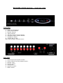
KORA Electronic Concept
Explorer 150SB
Hybrid integrated amplifier
User’s manual
Kora E.C. 8 bis, rue Claude Perrault, 31000 Toulouse, France
Web : www.kora.net - Email : [email protected]
Table of Contents
Page 1
Kora Electronic Concept
- the Kora team
Page 2
Read before use
- voltage
- installation
- speakers
- !!!
Page 3
Operating instructions
- connections
- inputs
- direct
- monitor
- turning on
Page 4
Starting up
- start procedure
- turning off
Audio/Video
- phase
Page 5
Trouble shooting
Page 6
Technical specifications
- guarantee
Page 7
Front and rear schemas
Page 1
Kora Electronic Concept
You have just acquired a Kora Explorer 150SB
integrated amplifier.
We thank you for your confidence and wish you
many hours of listening pleasure. Firstly, here are
a few words about the company and the people
behind Kora before you rush off to set up :
Kora Electronic Concept was created in 1990 by
a small team of electronics engineers working at
the time for the Aero Spatial complex in Toulouse,
south-west France.
The transition from designing power supplies to
producing Kora’s first hi-end tube amplifier, the
Design 30, took four years of research. Since
then we have produced many award-winning
designs, ranging from the hybrid Explorer 90SI
integrated to the Hermes D/A converter.
The present Kora team is :
François Philibert – Kora’s designer.
Gérard Payrastre – R & D engineer/managing
director.
Cyril Canod – Production manager.
Jeff Starrs – Communications and export sales.
Brice Aboucaya – Sales, France.
Alain De Stefani - Technician
Page 2
Please read this before setting-up
– it could save you a lot of trouble!
Voltage
Your Kora amplifier is workshop set from a fixed
mains supply voltage. This voltage is marked on
the rear plate of the unit. Before connecting,
check that this voltage is the same as your mains
supply. If you didn’t read this and your amp’s
blown up, don’t say we didn’t warn you! Read on
before turning on!
Installation
Please read carefully the complete instructions
detailed here before installing the 150SB in your
system.
If you are already familiar with a system set-up,
please make sure that you have connected your
speakers, via speaker cable, to the output
terminals of your 150SB before doing anything
else – turning on a tube amplifier without a load
connected can cause serious damage to your
amplifier. If you decide on a enclosed location for
your 150SB, make sure it is well ventilated.
Speakers
Connect your speakers to the speaker terminals
on the rear plate of your amplifier.
Red is positive and black negative.
That’s red to red and black to black!
The terminals take 4 or 8 ohm speakers and the
connection can be made with either banana plugs
or bare wire. Please read the next section before
going on to page 3 – it’s not that authoritative!
Don’ts !
Again, this is just to save you trouble!
Don’t expose your amplifier to excessive cold,
heat, sunlight, humidity or water - (e.g. the
swimming pool is not a good place to leave it).
Don’t use any chemicals when cleaning your
amplifier (hydrochloric acid will eat it, for
example). Just use a lightly dampened cloth.
Don’t go messing around inside (the amplifier)
without knowing what you’re doing (this could be
very nasty). You can always ask your dealer or
us if you need some help.
Don’t forget to keep the original packing (it
could increase in value over the years) – if you
move, you’ll curse yourself for having thrown it
out!
Page 3
Connections
- Source inputs
Operating instructions
So, now you can connect the different elements of
your system (CD, tuner etc.) to the appropriate
cinch (RCA) inputs at the rear of the amplifier.
These are the source inputs – they are identical.
Use high quality shielded cable in order to avoid
‘parasite noise’ and a weakening of the treble
frequencies. The listening of the sound source is
obtained by selecting the appropriate source.
- Direct
POWER IN allows you to attack the power section
directly. Use the Direct button on front plate and/or
the remote control handset.
It is not affected by the volume control.
You can connect, for example, an A/V processor
(the volume control of the processor will then be
active); a mixing desk or any other source that
delivers 2V RMS and has a volume control.
The PRE OUT output allows you to use the output
of the preamplifier.
The volume of the signal depends on the position of
the potentiometer on the front plate.
The gain of the preamp is graduated in decibels 0dB corresponds to a unitary gain. This output is
permanently available and does not depend on the
remote control handset.
- Monitor
This is a output/input loop for all types of recording
systems. The signal on the monitor output is that of
the input selected and does not pass by the
preamp. The output of the recorder is connected to
the input MONITOR IN.
This input is independent of the other inputs and is
validated by the MONITOR on the front plate or by
the remote handset.
Turning on
Turning on : The main on/off switch is situated on
the rear plate. Turn on the amplifier with this
switch : the numbers indicating the gain will light up
in blue on the front plate (8) ; the amplifier is in
stand-by mode. With normal use, you don’t need to
turn off with the rear plate switch; use the POWER
button situated on the front plate.
Never turn off the amplifier with the rear switch, nor
disconnect the mains cable without having first turned off the
unit with the POWER button as this can damage the power
section.
Page 4
- turning on
The 150 has a motorised volume control that is controlled
either by the front plate buttons or by the remote control
handset. It is usable from the first time you turn on the
unit as well as on stand-by mode.
ADVICE : Regulate your amplifier around –40dB the first
time you fire up, then adjust for your own taste.
Press the POWER button : the blue LED above will blink for
about 30 seconds. This is the necessary warm-up time for
the tubes. During this period no other control is available.
When the 30’ is over, the blue LED will remain alight and
you’re ready to listen to music.
The #1 input is automatically selected.
To go into the stand-by mode, press the POWER button :
the inputs cut out and the LED blue above the POWER
button will blink for 30’. At the end of this period, only the
volume/gain window will indicate that the unit is on standby mode. The energy used is inferior to 1w.
You may leave the unit in this mode.
Audio/Video
- phase
You may wish to use your 150SB in the context of an
audio/video set-up. With the 150SB, as we’ve seen, it’s
power section can be disassociated from the preamp
section. You can then connect an A/V processor which will
be driven by the 150SB preamp.
When you have different amplifiers & speakers working
together in a system, it’s very important to know the
‘phase’ of each of the amplifiers in order to obtain the
optimum sound. For example, the 150SB, when working
as an integrated, is in positive phase. However, when
disassociated, the power section of the 150SB is in
positive phase and the preamplifier of the 150SB in
negative or inverse phase.
Now, if your processor works in negative phase (ask
your dealer!) with the power section of the 150SB in
positive phase, you’ll need to inverse the red/positive &
black/negative connections of the speakers on the
processor – this way the phase will be positive and
listening levels comfortable.
One indication as to whether you have inverse phasing
when you shouldn’t, is when you find you need a great
amount of volume in order to hear properly. You’re
probably ‘out of phase’ if this happens!
Page 5
Trouble shooting
CUT-OUT WHILE THE UNIT IS IN USE :
Your Explorer 150 has a protection handled by the
micro-processor. In the case of a problem with the
power section (short-circuit/overload/etc), the fuses
situated on the supply, cut out. This is then detected
by the micro-processor that handles the 150, which
then passes automatically onto the protection mode
in less than a millisecond.
At this moment, all the lights will shut down,
including the gain numbers on the volume window.
This signifies a fault in the unit : please contact your
dealer or Kora directly.
This may happen the first time you fire up the unit
and is due to the fact that the supply is not yet
loaded. The remedy is simply to turn off the unit by
the switch on the rear plate, wait until the microprocessor has been reset and then turn on the unit
again.
If the problem persists, please contact your dealer.
Technical specifications
Page 6
EXPLORER 150SB
Integrated hybrid amplifier
Mains
Consumption
Fuse
Power
Frequency band
Slew rate
Inputs
Signal/noise
Dimensions
Weight
- guarantee
230V/50Hz (115V-USA)
500 watts max.
3A
2 x 100w @ 8 ohms
2 x 150w @ 4 ohms
0,2Hz @ 200Khz
<1µ microseconds
330mV/1 M ohms (10Vcc max)
112dB
460 x 370 x 200mm
13kg
Kora E.C. warrants to the original purchaser that this product shall be
free from defects in material or workmanship for two (2) years from
date of original purchase. Tubes : 90 days.
Correct maintenance, repair and use are important to obtain
performance from this product. Therefore, carefully read the User's
Manual. This warranty does not apply to any defect that Kora E.C.,
in its sole discretion determines is due to :
1) Improper maintenance or repair, including installation of parts
and accessories that do not conform to the quality and the
specifications of the original parts.
2) Misuse, abuse, neglect or improper installation.
3) Accidental or incidental damage.
During the warranty period, an authorized service facility will provide
free of charge both parts and labor necessary to correct defects in
material or workmanship. To obtain such warranty service, the original
purchaser must include a dated proof of purchase from the dealer when
returning the product, pre-paid, to the service center. Please contact
your dealer for details.
All repairs performed after the warranty period has expired will be
billed to the owner and will carry a 90 day warranty on parts and
labor.
EXPLORER 150 SB functions – front/rear view
Front plate
1. Power on/off selector.
2. Direct input selector.
3. Monitor selector
4. Inputs selector.
5. Increase output volume selector.
6. Decrease output volume selector.
7. Headphone socket.
8. Volume dial (in dB).
Blue LED indicates selected source.
Rear plate
1.
2.
3.
4.
5.
6.
7.
Direct input to the power section.
Direct output from the preamp section.
Monitor input.
Monitor output.
Line inputs.
Speaker sockets.
Mains socket.