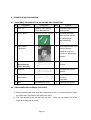
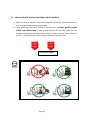
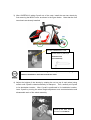
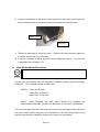
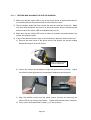
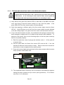
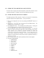
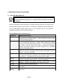
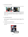
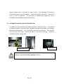
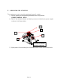
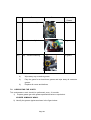
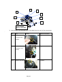
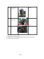
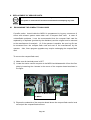
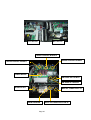
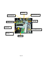
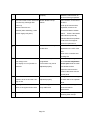
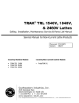
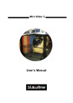
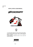
1
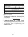
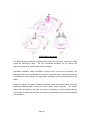
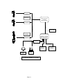
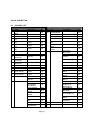
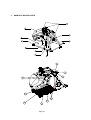
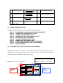
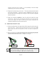
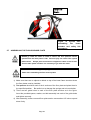
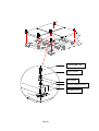
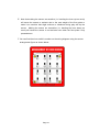
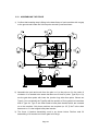
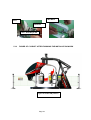
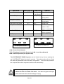
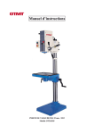
G426601E
REV1.2
INSTALLATION & USER MANUAL
l
l
l
To use this machine safely and correctly, read this manual carefully.
After reading this manual, be sure to keep it available nearby the product or
somewhere convenient so that it can be referred to whenever necessary.
When transporting or reselling this product, be sure to attach this manual to
the product.
© 2003, Simuline. Inc
BEFORE USING THIS PRODUCT
Thank you for purchasing our arcade use simulator equipment “CYCRAFT” game
machine.
Safety notes:
To ensure the safe usage of the product, be sure to read the following before using this
product. The following instructions are intended for the users, operators and the
personnel in charge of the operation of the product.
After carefully reading and sufficiently understanding the warning displays and cautions,
handle the product appropriately. Be sure to keep this manual available nearby the
product or somewhere convenient so that it can be referred to whenever necessary.
In this manual, explanations, which require special attention, are enclosed with dual lines.
Depending on the degree of potential hazards, the terms of DANGER, WARNING,
CAUTION, etc. are used.
Be sure to understand the contents of the displays before reading the text.
Indicates that mishandling the
product by disregarding the
instructions can cause severe
injury.
Indicates that mishandling the
product
by
disregarding
the
instructions can cause a slightly
hazardous situation that can result
in light personal injury and or
material damage.
Indicates that mishandling the
product by disregarding the
instructions can cause a
potentially hazardous situation
that can result in serious injury.
For the safe usage of the product, the following pictographs are used:
Indicates, “HANDLE WITH CARE”. In order to protect personnel and equipment,
this display is attached to places where the Owner’s manual and or Service
Manual should be referred.
Indicates a “Protective Earth Terminal”. Before operating the equipment, be sure
to connect it to the Earth line.
Page 2
Perform work in accordance with the instruction herein stated.
Follow instructions carefully paying special attention from the standpoint of accident
prevention. Failure to follow instructions can cause accidents. Instructions will point out
those jobs requiring trained technicians or servicemen.
Before installing the product, check for the electrical specification sticker.
SIMULINE products have a sticker on which the electrical specifications are detailed.
Ensure that the product is compatible with the power supply voltage and frequency
requirements of the location in which the machine is to be installed.
Install and operate the product only in places where appropriate and sufficient
lighting is available such that warning stickers can be clearly read.
Be sure to turn off power before working on the machine.
To prevent electric shock, be sure to turn off power before starting any work in which the
worker is exposed to the interior of the product.
Exercise great care when handling the monitor.
Some of the monitor parts are subjected to high-tension voltage. Even after turning the
power off, some components retain high-tension voltage. Only qualified service engineers
should perform monitor repair and replacement.
Be sure to adjust the monitor properly.
Do not operate the product with on-screen flickering or blurring unadjusted. Using the
product with the monitor not properly adjusted may cause dizziness or a headache to an
operator, a player, or the customers.
Specification changes, removal of equipment, conversion and or additions not
designated by SIMULINE is not allowed.
Do not make any engineering changes by alterations, unauthorized parts replacements or
other modifications under any circumstances. Should doors, lids and protective parts be
damaged or lost, refrain from operating the product, and contact the office where the
product was purchased from or the office of Simuline given in this manual.
SIMULINE shall not be held responsible for any accidents, compensation for damage to a
third party, resulting from unauthorized changes and modifications to the product.
When transporting or reselling this product, be sure to attach this manual to the
product.
*Description herein contained may be subjected to improvements and changes without notice
**The contents described herein are fully prepared with due care. However, should any question arise or errors be found,
please contact SIMULINE.
Page 3
INTRODUCTION OF THIS INSTALLATION & SERVICE MANUAL
This manual is intended to provide detailed descriptions together with all the necessary
information covering the general operation of electronic assemblies, electro mechanicals,
servicing control, spare parts, etc. for the product, CYCRAFT.
This manual is intended for the owners, personnel and managers in charge of operation
of the product. Operate the product after carefully reading and sufficiently understanding
the instructions. If the product fails to function satisfactorily, non-technical personnel
should under no circumstances touch the internal system. Please contact office where the
product was purchased.
Use of this product is unlikely to cause physical injuries or damages to property. However,
where special attention is required “IMPORTANT” symbol and message is given in the
manual as follows:
Indicates that mishandling the product by disregarding this message can cause
performance degradation or malfunctions.
DEFINITION OF PERSONNEL IN THIS MANUAL:
Non-technical personnel who do not have technical knowledge and expertise
should refrain from performing such work that this manual requires the arcade
maintenance personnel or a serviceman to carry out, or work, which is not
explained in this manual. Failing to comply with this instruction can cause severe
accidents such as electric shock.
Ensure that the arcade maintenance personnel or a serviceman performs parts
replacement, servicing & inspections, and troubleshooting. It is instructed herein that the
serviceman who has technical expertise and professional knowledge in the field should
perform particularly hazardous work.
The following definitions for personnel are used in this manual:
l
Arcade maintenance personnel
Those who have experience in the maintenance of amusement equipment and
vending machines, etc. and also participate in the servicing and control of the
equipment through such routine work as equipment assembly and installation,
inspections, and replacement of parts and consumables, etc. within the amusement
facilities and or locations under the management of the owner and owner’s operators
of the product.
Page 4
l
l
l
Service Person
Those who carry out inspections and maintenance services of the CYCRAFT
should be under the authorization of Simuline Inc or Sega (Japan / Europe / USA)
It is mandatory that the Service Person must have technical expertise
equivalent to that of technical high school graduates in the fields of electricity,
electronics and or mechanics.
Player
Persons who play games at facilities and shops where arcade amusement game
machines are installed.
Gallery
Persons who are onlookers near the games at facilities and shops where arcade
amusement game machines are installed.
REVISION RECORDS:
Language: English
Rev: 1.2
Modified Date: December 2003 (gb / sk / esk)
O/S Version: 1.64
Game Version: BGD0
PLACE TO BE CONTACTED:
For necessary repairs and parts, contact the Distributor whom you purchased your Cycraft.
SIMULINE, INC / CUSTOMER SERVICE
461-28
Jeon-Min-Dong
Yu-Sung-Gu
Deajeon
Korea
305-811
Phone:
Fax:
E-mail:
Web-Site:
+82-42-610-1010
+82-42-862-0795
[email protected]
www.simuline.com
Page 5
TABLE OF CONTENTS
BEFORE USING THE PRODUCT.
1. PRODUCT SPECIFICATION
1.1
GENERAL SPECIFICATION
1.2
MOTION SYSTEM DESCRIPTION
1.3
SAFETY SYSTEM DESCRIPTION
2. INITIAL INSPECTION
3. NAMES OF MAJOR PARTS
4. TRANSPORTING AND MOVING
4.1 EQUIPMENT REQUIRED FOR UNLOADING AND TRANSPORT
4.2 UNLOADING AND OPENING THE CRATE
4.3 UNPACKING AND INSTALLING REAR CASTER WHEELS
4.4 MOVING THE MACHINE
5. INSTALLATION INSTRUCTION.
5.1 LOCATION REQUIREMENTS
5.1.1
ENVIRONMENT REQUIREMENTS
5.1.2
ELECTRICAL REQUIREMENTS
5.2 EQUIPMENT REQUIRED FOR INSTALLATION
5.3 STEPS FOR INSTALLATION
5.4 SECURING IN PLACE (LEG ADJUSTER ADJUSTMENT)
5.5 CONNECTING THE HEAVE ACTUATOR
5.6 CONNECTING THE SAFETY LINK
5.7 ASSEMBLING THE FLOOR SENSOR PLATES
5.8 SETTING THE PHOTO SENSORS
5.9 COIN MECHANISM INSTALLATION
5.10 CONNECTING THE ELECTRIC POWER SOURCE
5.11 POST INSTALLATION TESTING AND INSPECTION
5.11.1 TESTING AND ALIGNING THE PHOTO SENSORS
5.11.2 TESTING AND ADJUSTING THE FLOOR PRESSURE SENSOR
5.12 ASSEMBLING THE FENCE
5.13 FIGURE OF CYCRAFT AFTER FINISHING THE INSTALLATION WORK
Page 6
6. OPERATION & ADJUSTMENT INSTRUCTION
6.1
DESCRIPTION OF INDICATORS AND SWITCHES ON THE OPERATION
PANEL
6.2
TURNING THE POWER ON AND OFF
6.3
ADJUSTMENT OF THE SPEAKER VOLUMES
6.4
SETTING VIDEO MONITOR PARAMETERS
6.5
USING THE LCD PANEL TO SET CONFIGURATIONS
6.5.1
SETTING THE SAFETY SENSOR PARAMETERS
6.5.2
SETTING TCP/IP CONFIGURATION
6.5.3
VIEWING THE TOTAL COIN COUNT (STATISTICS)
6.6
SETTING THE COIN AND CREDIT CONFIGURATION
6.7
GAME PLAY OPERATION
7. MAINTENANCE & INSPECTION INSTRUCTION
7.1 ROUTINE MAINTENANCE
7.2 INSPECTION OF CRITICAL BOLTS AND CONNECTIONS
7.3 VERIFICATION OF SNAP RINGS
7.4 CHECKING WELD CONDITION
7.5 CHECKING THE ACTUATOR DRIVE BELT
7.6 CLEANING THE MSCU AIR FILTERS AND FAN
7.7 LUBRICATING THE ACTUATORS
7.8 LUBRICATING THE JOINTS
8. SERVICE & REPLACEMENT INSTRUCTION
8.1 EXCHANGING THE COMPACT FLASH CARD
8.2 REPLACEMENT OF SERVO CONTROLLER BOARD
9. TROUBLE SHOOTING
9.1 TROUBLESHOOTING TABLE
9.2 CONTROLLER ERROR MESSAGE TABLE
10. ELECTRIC SCHEMATICS
10.1 SCU SCHEMATIC
10.2 CABIN SCHEMATIC
10.3 MCU SCHEMATIC
Page 7
1.
PRODUCT SPECIFICATIONS
1.1 GENERAL SPECIFICATIONS
When the cabin is at the power- on position
Approximately
2200 mm
2150 mm
2870 mm
1000 mm
4050 mm
2900 mm
Page 8
Category
Coin-op interactive motion simulator
Play type
Main Machine Dimensions
(At the power-on position.)
Main Machine Dimensions
(Transport dimensions)
Fence Dimensions
Weight
Arcade game
2870 mm (L) × 2150 mm (W) × ~ 2200 mm (H)
2890 mm (L) × 1540 mm (W) × 2020 mm (H)
4050 mm (L) × 2900 mm (W) × 1000 mm (H)
Main Machine: (Approximately) 900 kg
Fence: (Approximately) 110 kg
Single phase AC 200/208/220/230/240 V,
50/60 Hz, (Max) 10A
Single Player
120 Kg
Semi-enclosed with seat belt
Electric Power
No. Of Passenger
Passenger Weight Limit
Compartment
1.2 MOTION SYSTEM DESCRIPTION
The motion actuation system used in Cycraft is a very unique, high tech system that
distinguishes Cycraft from other simulator products.
The motion system has the
following special features:
l
Fully electric motion system: The actuators are fully Electrical (no hydraulics),
making it superior in terms of maintainability and transportability.
l
Patented “inverted” configuration (virtual 5 DOF system):
The motion
actuators are configured such that pitch and roll rotational motions have their center of
rotations above the passenger.
This patented technology enables the simulator to
produce the effects of a 5 X DOF (degrees of freedom) motion system although it has
only 3 DOF mechanically.
Therefore, fast and accurate motion cueing is made
possible without increasing costs.
Page 9
3 DOF Motion Systems
The heave actuator produces up/down heave motion by rocking the rocker arm, which
holds the passenger cabin.
The two suspended actuators on the rocker arm
assembly produce the relative pitch and roll motions
Separate controllers inside the MSCU control each of the linear actuators. The
controllers are in turn connected to the motion controller board, which generates the
commands for each actuator via high-speed industrial Control Area Network (CAN)
cable.
During the game, the game computer regularly sends the attitude data and other
dynamic properties data in real time to the motion control computer.
The motion
board then calculates in real time, the motion necessary to give the passenger the
best feeling of reality and converts this motion to commands for the motion controllers
and actuators.
Page 10
Servo Control
Board #3
Mitsubishi
Motion Computer
3 x Boards
Flash Rom Fitted
Servo Control
Board #2
TCPIP
CAN NETWORK
LAN cable
Toshiba
Sega Game System
NAOMI 2 or Triforce,
Dimm Bd, GD Rom
Drive, I/O Bd, PSU.
Servo Control
Board #1
I / O Board
Handle
Pedal
SYSTEM DIAGRAM OF CYCRAFT
Page 11
Game
Audio
Monitor
System
1.3 SAFETY SYSTEM FEATURES
Operators of Cycraft should familiarize themselves with the safety features of Cycraft
to ensure that they are functioning properly for safe and proper operation.
Cycraft
incorporates a number of safety features to ensure that accidents and injury will not be
caused to passengers and on-lookers due to the motion of the simulator.
Following
is a description of each safety feature.
l
Fence:
A sturdy metal fence with an entrance door is provided with Cycraft. It will
ensure that on-lookers and waiting players will be kept a safe distance from the moving
cabin. The fence will also prevent on-lookers from approaching too closely and
unnecessarily tripping the photo sensors during play. Warning signs and regulation
signs are attached to the fence and door to inform customers and on-lookers.
l
Side Photo Sensor:
Two photo sensors attached on either side of the outer frame
of Cycraft cause the motion to stop if any obstacle obstructs the line between the
sensor and the reflective plate during play.
Therefore, even if people enter the fence
and approach Cycraft when it is moving, safety is ensured since the photo sensor will
be tripped and motion stopped.
Motion resumes 3 seconds after the obstacle is
removed.
l
Floor Sensor:
The floor plate beneath the cabin (seat) is a pressure sensor, which
activates when stepped on. It is guaranteed to detect pressures above 20 kg.
Activation of the floor sensor will stop the Cycraft motion as with the photo sensors
described above. Motion will re-activate 3 seconds after the pressure is removed.
The floor sensor guarantees safety even in the case when people somehow approach
Cycraft without tripping the photo sensor and also in the case when the passenger falls
from the cabin during play for any reason.
l
Seat Belt Sensor:
The seat belt buckle in Cycraft is equipped with a sensor that
detects when the seat belt is fastened or not. Cycraft will not start the game unless
the seat belt is fastened properly. Also, if the seat belt is unfastened during the game,
the motion will stop until it is re-fastened.
l
Game Stop Button:
This button, located inside the cabin allows the player to stop
the game anytime during play.
Pressing this button will terminate the game and lower
the cabin to the initial position.
l
Motion Stop Switch:
The motion stop button located behind the coin chute case
stops the motion when pressed.
Motion restarts 3 seconds after the button is
released. This button can be pressed by outside on-lookers or by the operator in
Page 12
case the photo or floor sensors cannot be activated or the motion must be stopped for
safety reasons.
l
Power Cutoff Switch:
This button located inside the operator panel but accessible
through a sliding door on the operator panel cover shuts off the main power to the
system. Pressing this switch will stop the ongoing motion of the system but will not
stop and hold the position of the cabin as with the other buttons and safety features.
Instead, the cabin will slowly pitch forward (nose down) and glide down to its lowest
position due to its own weight. Therefore, this switch should NOT be pressed
when the motion needs to be stopped.
This switch should only be used in the rare
emergency case when power must be cut off such as when a fire is ignited.
NEVER press the power cutoff switch when there is a person or obstacle
UNDER the cabin. The cabin will glide down after the switch is pressed and
can cause serious injury to anybody under the cabin.
l
Safety Link (page 29) and Safety Oriented Mechanical Design:
The safety link
located on the rear part of the rocker arm functions to prevent a free fall of the cabin in
case the heave actuator is broken off from the rocker arm.
The two rocker arm
bearings and center shaft of the rocker arm is designed such that even if one of the
bearings comes loose, the shaft will be held up by the frame to prevent a fall. The
cabin is suspended by three universal joints (central joint and two joints connecting to
the actuators).
Therefore, even if one of the joints fail, the other two will support the
cabin to prevent a complete free fall.
l
Other Safety Features:
Cycraft is equipped with Brake Boards to supply step down
voltages to critical motor controller circuits, in case of power outages so that the cabin
(seat) does not fall abruptly. At power outages (and also when the power cutoff switch
is pressed) the motor control circuits with brake boards will make sure that the
simulator will shutdown and rest softly.
l
Safe Inherent Design:
The basic configuration of the inverted motion system allows
for the cabin to be suspended much lower from the ground than conventional motion
simulators. Also, it is dynamically much more stable by making it very difficult to tip
the cabin over to it’s side.
Thus, the Cycraft structural design is inherently much safer
than conventional motion simulators.
Page 13
INITIAL INSPECTION
2.1 PACKING LIST
CYCRAFT PACKING LIST (1/2)
No
1
2
3
4
5
6
7
Item
CYCRAFT
Main
Body
Rear Caster (R)
Rear Caster (L)
Floor Sensor Plate
(A)
Floor Sensor Plate
(B)
Floor Sensor Plate
(C)
Floor Sensor Plate
(D)
CYCRAFT PACKING LIST (2/2)
Description
Qty
No
Item
Description
Qty
1 ea
19
Hex Bolt M8x20L
10 ea
1 ea
1 ea
Hex Nut M8
Clamping Filter
7 ea
1 ea
A Type
1 ea
Fence Sign Plate
4 ea
B Type
1 ea
C Type
1 ea
D Type
1 ea
Fence Sign Ring
Clip
Play
Instruction
Sticker
Installation & User
Manual
8 ea
1 set
1 ea
8
Boarding Step
1 ea
9
1 ea
1030 mm
1 ea
Cable Tie
5 ea
690 mm
1 ea
Pushbutton Lamp
2 ea
550 mm
1 ea
Grease Gun
1 ea
13
14
15
Coin Chute Tower
Fence
Holding
Bracket (A)
Fence
Holding
Bracket (B)
Fence
Holding
Bracket (C)
Gate Door (R)
Gate Door (L)
Fence Pole (A)
Floor Sensor
Micro switch
Monitor BD Fuse
400g
A Type
1 ea
1 ea
4 ea
16
Fence Pole (B)
B Type
2 ea
17
Fence Pole (C)
C Type
3 ea
18
Wire Mesh
1200 mm
6 ea
1800 mm
2 ea
Safety Link
1 ea
Boarding Step
Joint Bracket
2 ea
10
11
12
19
Installation Kit Box
20
Spare Parts Box
2 ea
1 ea
Fence U Bracket
SUS Wrench Bolt
M6x10L
SUS Wrench Bolt
M6x25L
32 ea
Grease
Paint (Red)
Fence U Bracket
SUS
Wrench
Bolt
M6x10L
SUS
Wrench
Bolt
M6x25L
SUS Nut M6
Count Sink Head Bolt
M6x 10L
Hex Bolt M12 x 35L
Hex Bolt M8x30L
DU Bush10*15
Rubber Washer
Hex Bolt M8x20L
32 ea
Hex Nut M8
2 ea
32 ea
Truss Bolt M4 x12L
5 ea
SUS Nut M6
32 ea
Counter Sink Head
Bolt
Hex Bolt M12 x 35L
Hex Bolt M8x30L
DU Bush10*15
Round
Head
M5x10L
Harness
for
mechanism
4 ea
Bolt
coin
200ml
2 ea
2 ea
2 ea
2 ea
2 ea
2 ea
2 ea
2 ea
4 ea
1 set
10 ea
21
NAOMI2 Carton
1 ea
8 ea
22
GD-ROM Carton
1 ea
Page 14
Rubber Washer
2.2 GENERAL RECEIVING INSPECTION
Only QUALIFIED SERVICE PERSONNEL should carry out inspection.
All Simuline products are manufactured so that operation is possible immediately after the
proper installation.
However, it can be possible that an irregular situation occurs during
transport and delivery to prevent this. To verify that transport and delivery has be carried
out without irregularity, a proper general receiving inspection should be made as follows:
l
Are then any dented parts or defects (cuts, etc.) on the external surfaces of the
product?
l
Are castors and leg adjusters present and undamaged?
l
Do the power supply voltage and frequency requirements match with the local supply?
l
Are all wiring connectors correctly and securely connected? Unless connected in the
correct direction, connector connections cannot be made successfully. Do not insert
connectors forcibly.
l
Are all IC’s of each IC board firmly inserted?
l
Does the power cord have any cuts or dents?
l
Do fuses meet the specified rating?
l
Are such units such as monitors, control equipment, IC boards, etc. firmly secured?
l
Are all earth wires connected?
l
Are all accessories available?
l
Can all doors and lids be opened with the accessory keys and/or tools?
Page 15
3.
NAMES OF MAJOR PARTS
18
17
16
28
12
15
13
14
11
Page 16
26
22
27
21
19
20
23
29
25
No.
1
2
3
4
5
6
7
Item
Cabin (Seat + Monitor)
Main Frame
24
Description
Carries the player and moves during operation.
Holds the cabin, actuator system and
electronics.
Actuators
Three electric linear actuators that move the
cabin in 3 DOF (degrees of freedom). The two
actuators on top of the cabin creates pitch and
roll motions. The actuator behind the cabin
creates heave motion.
Motion System Cabinet Houses all the control electronics and electrical
Unit (MSCU)
components.
Coin Chute Tower
Carries the coin chute mechanism.
Motion Stop Switch
Pressing this button will stop the simulator
motion but game play will continue. Motion
resumes 3 seconds after the switch is released.
This button can be used in case of emergency
when motion must be stopped.
Operator Panel
Houses indicators and switches to set and
control Cycraft. Refer to Chapter 2 for details.
Page 17
8,9
16
Safety Photo Sensors & There are 2 photo sensors on each side of the
Reflectors
outer frame. If any of the sensor lines are
obstructed, the simulator will stop in its current
orientation until 3 seconds after the removal of
the obstruction.
Safety Floor Sensor
The metal floor plate underneath the cabin is a
pressure sensor that stops the simulators
motion when stepped on. The simulator will
begin to move again 3 seconds after the
removal of the pressure.
Safety Floor Sensor Plates 11 = A type, 12 = B type, 13 = C type,
14 = D type
Floor Sensor Indicator Lamp (Green) goes off when the floor sensor is
Lamp
activated.
Safety Link
Safety link connected to the rocker arm.
17
Heave Actuator Joint
18
Rocker Arm
Tilts up and down to create heave motion.
19
Start Button
Begins the game after coin is inserted.
20
View Button
21
Game Stop Button
22
Video Control Buttons
23
Steering Wheel
Changes the driver’s view perspective during
play.
Terminates the game and lowers the cabin to
the initial position.
Removing this cover exposes the control
buttons to adjust video screen parameters.
Refer to Chapter 2 for details.
Produces steering input for the game.
24
Accelerator Pedal
Produces accelerator input for the game.
25
Brake Pedal
Produces braking input for the game.
26
Monitor
Displays game graphics.
27
Front Speakers
Produces audio effects.
28
Rear Speakers
Produces audio effects.
29
Subwoofer
Produces audio effects with low frequency
10
11~
14
15
Page 18
4. TRANSPORTING AND MOVING
4.1 EQUIPMENT REQUIRED FOR UNLOADING AND TRANSPORT
No
1
Equipment
Description
Fork Lift
Capacity over 1500 kg
Qty
Purpose
1
Lift and transport out of
Boom attached fork
2
Wood block
10 cm x 10 cm x 100 cm
packing crate.
4
Set under the base
frame so that fork can
be inserted and
removed easily.
3
Rear caster
2
(Supplied)
Used together with front
casters (already
installed) to roll the
machine to destination
location.
4
Socket
wrench
&
1
Extension bar
Attaching the rear
casters.
(Over 200 mm)
5
Wrench
1
Adjusting the level of
casters.
6
Philips
type
1
screwdriver
Loosening and
securing
truss bolts
7
4.2
Bolt
Hex head M12 x 35 L
6
Attaching the casters
UNLOADING AND OPENING THE CRATE
1) When unloading the crate from the container or truck, it is recommended to insert
the forklift from the heavier rear side of the crate.
2) The crate should not be opened from the front. Open the rear and/or one of the
sides when opening the crate.
Page 19
4.3
UNPACKING AND INSTALLING REAR CASTER WHEELS
1) After the crate is opened, unpack the separate accessories and components so
that the main simulator body is accessible.
2) Insert forklift from the rear of Cycraft or from the side.
DO NOT INSERT FORKS
FROM THE FRONT SIDE. When inserting forks from the side, make sure the
forks are positioned to enter the cutoff sections in order to ensure Cycraft does not
tip over.
Insert forks fully until the tips are visible on the other side.
Fork Lift Insert Mark
DO NOT INSERT FORKS FROM THE FRONT SIDE
Page 20
3) After CAREFULLY taking Cycraft out of the crate, install the rear two wheels by
first removing the MSCU cover as shown in the figure below.
Note that the front
two wheels are already installed.
3 x Hex head Bolt M12 x 35L
Socket wrench (19mm) &
Extension bar
(Over 200 mm)
Be careful not to step on and damage the floor pressure sensor springs and
switches installed on the frame beneath the cabin
4) Adjust the heights of the wheels by rotating the nut on top of each wheel using
wrench until Cycraft is raised sufficiently for transport. Then, carefully roll Cycraft
to its destination location. After Cycraft is positioned in it’s installation location,
lower Cycraft by turning the wheel height adjustment nuts counterclockwise and
disassemble each of the wheel assembly.
To lift up the base frame,
Page 21
turn the nut clockwise
4.4
MOVING THE MACHINE
Only QUALIFIED SERVICE PERSONNEL should carry out this operation.
Cycraft simulator is a complex & delicate machine. Special care must always be taken
when handling Cycraft.
When moving Cycraft within a facility, it is recommended to utilize the casters provided
with the product. It is not necessary to disassemble the heave actuator and/or the safety
link. Only the fence and boarding step with coin chute need to be disassembled.
When Cycraft must be moved long distances by truck, it is recommended that the heave
actuator and safety link be disassembled such that the cabin is set securely on the base
of the outer frame.
Trucking Cycraft without the heave actuator disassembled can cause
mechanical damage to the actuator due to shock and vibration during transport. Be sure
to lay the wooden plate between the cabin and the base frame as when Cycraft was
delivered.
This plate protects the floor sensors and switches during transport.
l
When moving the machine, be sure to remove the power cord and plug
from the power supply. Moving the machine with the power cord inserted can
cause the power cord to be damaged, resulting in a fire or electric shock when
installed in a new location.
l
When moving the machine, with the heave actuator in the assembled
state, make sure that the machine is not exposed to high vibrations and shock.
Mechanical and structural damage can result.
Page 22
5. INSTALLATION INSTRUCTION
5.1
LOCATION REQUIREMENTS
5.1.1 ENVIRONMENT REQUIREMENTS
Cycraft is designed for indoor use and should never be installed outdoors.
Environment and facility requirements are as follows:
Installation location
Ambient temperature
Humidity
Min. Entrance
dimensions
Min. Ceiling Height
Min. Footprint
(incl. Fence)
Min. Floor Loading
Cleanliness
l
Indoor use only
5 to 40 C
10 to 70 % (no condensing)
1540 mm (W) x 2100 mm (H)
2400 mm (H)
4050 mm (L) x 2900 mm (W)
310 kg/m2
Free of dust and debris
Never install the game machine outdoors
Also avoid the following locations even though they are indoors.
l
Near a leaky roof, close to any kind of dripping water, or any place with high
humidity that can condense
l
Close to an indoor pool or showers
l
Exposed to direct sunlight
l
Exposed to direct heat, such as close to a heater vent, or in a highly heated
room
l
Close to flammable or volatile chemicals, or dangerous materials
l
Avoid floors that slope(any slope more than 2 degrees)
l
Avoid strong vibrations
l
Avoid dusty locations
l
Avoid any location that does not allow enough space around the machine
Page 23
5.1.2 ELECTRICAL REQUIREMENTS
The facility should provide the following electrical power outputs for Cycraft:
Input Voltage
Single Phase
AC 200V, 208V, 220V, 230V, 240V
Frequency
50 / 60 Hz
Rated Current (Max)
8.5 Amp
Peak Current (Max)
10 Amp
Building Circuit Breaker
13 Amp
(Recommended)
Note:
The average power requirement is measured power consumption during
normal operation.
Peak power requirement is theoretical short-term peak power
possible for short times during special driving conditions.
Therefore, it is
recommended that facility power to be based on peak power requirements for the
best results.
5.2 EQUIPMENT REQUIRED FOR INSTALLATION
No
Tools
1
Philips
Description
type
Q’ty Purpose
1
screwdriver
2
Loosening and securing
truss bolts
Wrench
1
Adjusting the levers.
1
Boarding step,
(19 mm ~ 27 mm)
3
Hex Key
( 6mm)
4
Coin Chute Tower
Hex Key
1
Fence
1
Photo sensor, mirror
2
Turnbuckle
( 5mm )
5
Hex Key
(2.5 mm)
6
Spanner (22 mm)
Safety Link
Page 24
7
Spanner (19 mm)
2
Heave actuator (M12)
8
Spanner (13 mm)
2
Floor sensor plate (M8)
9
Spanner (10 mm)
1
Fence mesh (M6)
10
Mini Socket Wrench
1
Coin mechanism
(5/16 inch)
5.3 STEPS FOR INSTALLATION
Installation should be carried out according to the following steps.
STEP 1
STEP 2
STEP 3
STEP 4
STEP 5
STEP 6
STEP 7
STEP 8
STEP 9
STEP 10
SECURING IN PLACE (LEG ADJUSTER ADJUSTMENT)
CONNECTING THE HEAVE ACTUATOR
CONNECTING THE SAFETY LINK
ASSEMBLING THE FLOOR SENSOR PLATE
SETTING THE PHOTO SENSORS
COIN MECHANISM INSTALLATIONS
CONNECTING THE POWER CORD
TESTING AND ALIGNING THE PHOTO SENSORS
TESTING AND ADJUSTING THE FLOOR SENSOR
FENCE ASSEMBLY
5.4 SECURING IN PLACE (LEG ADJUSTER ADJUSTMENT)
After Cycraft is placed in location, the level pads must be adjusted correctly to prevent
Cycraft from moving about the floor due to its own motion. Cycraft has 3 stationary
rubber pads and 4 adjustable level pads as shown.
POSITION OF 3 PCS RUBBER
Front side of CYCRAFT
PADS & 4 LEVERS
(TOP VIEW)
RUBBER
LEG
PAD
LEVELER
Page 25
The processes to place Rubber Pads and adjust the Leg Levelers are as follows:
1) Make sure that all of the four adjustable Leg Levelers are not touching the ground.
If it is, raise it so that only the three rubber pads touch the ground.
mass of Cycraft is very near the central rear rubber pad.
The center of
Therefore, it is
advisable to have two people stand on top of the front two rubber pads to make
sure the three pads are touching the ground securely.
2) Lower the 4 adjustable Leg Levelers so that they touch the ground and evenly
hold the weight of Cycraft. Do not extend them so much that the central rubber
pad is raised from the floor.
To secure the machine,
turn the adjusting nut
clockwise.
Adjusting Nut
Level Pad
3) After you are satisfied that the pads are set correctly, you can proceed to
assemble Cycraft.
However, after assembly, the pads should be observed during
the test runs and adjusted further if there seems to be excessive movement or
uneven loading and lifting of the pads.
5.5
CONNECTING THE HEAVE ACTUATOR
At no time during the installation and assembly process should personnel
place body parts or go beneath the cabin. Take note that there is always the
danger of the cabin falling.
1) Install the turnbuckle firmly between the frame and rocker arm as shown.
Page 26
Turnbuckle
2) Turn-buckle works as a kind of ratchet mechanism. Lower the rear end of the
rocker arm by ratcheting up the turnbuckle clockwise as seen from the rear until
the turnbuckle almost go to its limit.
During this process the cabin will be lifted up. As it lifts up it will simultaneously tip to
wards the front and slide backwards
3) Disassemble the heave actuator holding bracket and free the heave actuator.
Make sure the actuator is supported so that it does not fall over to one side when
the holding bracket is disassembled.
4) Rotate the actuator piston counterclockwise as seen from the top to extend the
actuator.
Match the 4 bolt holes of the flange and rocker arm mating part close
Page 27
enough so that bolts can be inserted.
It is not necessary to have the flange
mated exactly to the rocker arm at this stage.
5) Tighten the four bolts evenly one at a time.
as the bolts are tightened.
The heave actuator piston will extend
Tighten all four bolts to 1200 kgflcm torque. Mark the
bolt and relative side of the flange as in the figure so that it can later be inspected
easily for looseness.
6) Rotate the turn-buckle clockwise to lower the cabin and extend the heave
actuator fully. When the bolts connecting the turnbuckle to the rocker arm feels
loose and the weight of the cabin is held fully by the actuator, disassemble the
turnbuckle completely from each end and remove it.
5.6
CONNECTING THE SAFETY LINK
1) Position the safety link as in the figure below with the longer link section above the
shorter link section.
Tighten the bolt connecting the link to the rocker arm to 1200
kgf lcm torque and mark the bolt position so that it can later be inspected for
looseness.
2) Make sure that the link is bent such that the center-connecting joint protrudes
forward and the link is bent in the “<” shape as in the figure.
Incorrect
Correct
If the link is installed incorrectly in the reverse “L” shape (see figure), the
link will hit the actuator and actuator joint when heave motion occurs and
the system will be damaged. Make sure it is installed correctly.
Page 28
Longer Link
Section
Figure
of
Cycraft
assembling
the
after
heave
actuator and safety
assembling
5.7
ASSEMBLING THE FLOOR SENSOR PLATE
NEVER go under the cabin to install or service the floor pressure sensor
system when the main power is ON.
Serious injury can result if the system
malfunctions. Always place a structure to support the cabin in case it falls.
Turn the main power off when it is necessary to go under the cabin.
Be careful not to damage the springs and micro switches on the bottom
frame when assembling the floor sensor plates
1) Make sure there are no objects or debris on top of the lower frame structure where
the floor plates must be installed.
2) Two persons should lift each of the 4 sections of the floor plate and place them in
the specified position. Be careful not to damage the springs and micro switches.
3) There are two guide holes in each of the floor plate sections as in the figure.
Insert the provided spacer, washer, and bolt assembly into each of the guide holes
and tighten securely.
4) After assembly, make sure each floor plate section moves about 1/2 inches up and
down freely.
Page 29
link
Hexa bolt M8 x 30L
Spring Washer
Flat Washer
Rubber Washer(11*20*3t)
DU Bush 10*15
Page 30
5.8
ASSEMBLING THE BOARDING STEP AND COIN CHUTE TOWER
The boarding step and coin chute tower should be assembled at this stage so that
electrical connections to the coin mechanism can be made and functional testing of
Cycraft can be performed before final assembly of the fence.
To assemble the
boarding step and coin chute tower, follow the next procedure.
1) Attach the coin chute tower on the boarding step.
Coin Chute Tower
Boarding Step
Flat Washer
Spring
Washer
2) Then attach two boarding step joint bracket to the boarding step.
Hex head Bolt M8
Spring Washer
Boarding Step Joint
Bracket
Page 31
Flat Washer
3) Position the assembled boarding step and secure it to the base of Cycraft as
shown.
Hex head Bolt M8 x 30L
Spring Washer
Flat Washer
5.9 SETTING THE PHOTO SENSORS
There is a set of photo sensor and reflective plate on each side of Cycraft. Set the
photo sensor system as follows:
1) Loosen the setscrews of the reflective plate arms and rotate the arms so that the
reflective plates point backwards at 90-degree angles from the sides of Cycraft
and tighten the setscrews.
Tool : HEX KEY 2.5 mm
Page 32
2) Loosen the setscrews of the photo sensor arms and unfold them so that the arms
point outward and the photo sensor lens points toward the reflective plate.
Sensor Lens
Set Screw
3) Tighten the setscrews to secure the arms. Remove the clear protective plastic on
the photo sensor lens if it is still intact.
4) It may be necessary to adjust the photo sensor alignment later on.
This process
is described in the Chapter 5.12.
5.9
COIN MECHANISM INSTALLATION
Only Qualified Service Personnel should carry out this operation.
Cycraft uses the standard coin box faceplate provided by Happ Controls and Sega
Enterprise. The compatible model numbers are,
HAPPS:
Frame 42-3272-00
Lower Door 42-3245-16
Upper Door 42-7201-00
SEGA:
ASAHI Standard. Also SR3, NRI & Alberici coin validators are
electronically compatible. Contact your distributor for coin loom specifications.
The coin chute door and coin mechanism to be used must physically match the above
coin chute frame. When fitting the coin mechanism to the door please refer to the
specific manufacturers installation instructions for that coin mechanism.
Page 33
To mechanically assemble the coin chute frame and cash door,
1) Loosen all of the bolts on the frame that secure the clips.
2) Turn all clips in towards the door.
3) Position the door into the aperture in the coin chute tower.
4) Turn the clips around so that they will hold the door in the machine.
5) Tighten all of the bolts.
5.9.1 WIRING CONNECTION
1) Route the bundle of cables into the coin chute tower.
Insert the cables through this
hole and secure
the end of bellows with truss
M4 bolts and nuts attached
in shipping. Please ensure
to use the Rubber Bellows
& cable ties supplied with
the Cycraft
Page 34
2) There are 4 electric connectors, the P1 (10 pins), P2 (4 pins), P3 (2 pins) and
P4 (2 pins) for Coin Validator / Bill Acceptor & Coin Meter interfacing to the
Sega I/O circuit. The pin assignments for each connector are:
P4 (2p)
P3 (2p)
P1 (10p)
P2 (4p)
P1 (10 pins White plug : for coin validator)
1 ---------- GND (wire colour GREEN)
2 ---------- +12V (wire colour YELLOW)
7 ----------- COIN SW1 in Sega I/O BD (wire colour BROWN)
8 ----------- COIN SW2 in Sega I/O BD (wire colour WHITE)
P2 (4 pins : for bill acceptor power & 12V lamp)
1------------
110V AC(R)
2------------- 110V AC(T)
3------------- +12V (wire colour BROWN)
4------------- GND (wire colour WHITE)
P3 (2 pins : for coin meter for chute #1) {always ACTIVE with Electronic
Mech}
1------------
COIN METER 1 for Sega I/O BD (wire colour BROWN)
2------------- +5V (wire colour WHITE)
P4 (2 pins : for coin meter for chute #2) {SPARE meter connection}
1------------
COIN METER 2 for Sega I/O BD (wire colour YELLOW)
2------------- +5V (wire colour GREEN)
3) Attach the coin chute door and coin selector. Then, perform the wiring referring to
the electric schematic #1 of the SCU provided in session 10.1 to determine the
correct connection method.
Page 35
5.10 CONNECTING THE POWER CORD
Before supplying power to the power cord, make sure that the system is
properly configured inside the MSCU for your facility power supply voltage.
Improper configuration can damage your system permanently.
Cycraft is designed to accept the single phase 200V, 208V, 220V, 230V, and 240 VAC,
50/60 Hz power sources to support the different electric power systems in different
parts of the world.
However, the system must be configured correctly for each power
supply voltage by connecting an electric line to one of three available terminals inside
the MSCU.
Specification of the main AC power cord (Recommended)
Main AC Power Cord
Isolation Tube
UL 16 AWG
2 sq. - 4 O
UL 16 AWG
2 sq. - 4 O
UL 16 AWG (Green Color)
Isolation Tube
1.25 sq. - 4 O
300 mm
Prepare the main AC power cord compatible with above specification description.
To connect and/or verify the power cord voltage setting,
1) Open the MSCU cover in the rear of the simulator.
Before opening the MSCU cover, make sure the power line is NOT
connected to the building power source and that there is no electrical
power supplied to the system to prevent injury from electrical shock.
Page 36
2) Locate the input voltage selection terminal block and the voltage selection wire
shown in the picture below.
3) Connect the voltage selection wire to the terminal that matches your facility supply
voltage according to the input voltage selection terminal wiring instruction.
4) Locate the power cord connection terminal and connect the two power lines and
the earth line of the power cord as shown below. Make especially sure that the
earth line is properly connected for safe and proper operation.
T0
R0
Positive (Brown)
Negative (Blue)
Primary Earth
(Green Wire)
Point.
5) Verify all connections & connect power cord to the facility input voltage source.
Page 37
6) Go to the Operator Panel (page 44) and verify that the red LED labeled “Main
Power” is lighted. Before proceeding to start the power up sequence of Cycraft,
operators should familiarize themselves with the switches and controls on the
Operator Panel.
5.11 POST INSTALLATION TESTING AND INSPECTION
After the mechanical and electrical installation is complete, it is necessary to carry out
a final checking procedure and make some adjustments if necessary.
To carry out
the final tests and adjustments, you must power UP Cycraft.
Carry out the Power-UP sequence according the procedure outlined in section 6.2.
Before you power-up Cycraft, make sure of the following:
(a) The power cord is connected to the correct voltage outlet and the green main
power LED is lighted.
(b) The emergency power off switch and motion stop switch (behind the coin chute
box) are released.
Make sure there are no personnel or objects under or in the area of the cabin
before switching the power on. The power up sequence will move the cabin
and personnel can be injured.
Make sure there are no passengers in the cabin when power is turned on.
The extra weight of the passenger can cause a fault in the power ON
sequence.
After successful power UP, it is possible that a beeping sound is heard and the red
LED labeled “Safety Sensor” on the Operator Panel is lighted.
This indicates that
adjustments on the safety sensors (floor sensor and/or photo sensors) are needed.
Even if the beeping sound is not made, read the following sections and verify that the
sensors are in the best operating conditions.
Page 38
5.11.1 TESTING AND ALIGNING THE PHOTO SENSORS
1) Make sure that the Yellow LED on top of the photo sensor is lighted when there is
no obstacle between the photo sensor and the reflective mirror.
2) Tap and slightly shake the photo sensor bar and the reflective mirror bar.
Make
sure that small vibrations and motion of the photo sensor and the reflective plate
does not cause the Yellow LED to instantaneously turn off.
3) Make sure that the Yellow LED turns off when an obstacle is placed between the
sensor and reflective plate.
4) If any of the above tests fail, carry out the following to align the sensor and mirror:
A. Remove the steel cover of the photo sensor and expose the sensor holding
bracket and screws as shown below.
Bolts For Photo sensor
Position Adjustment
B. Loosen the screws as necessary to align the photo sensor correctly. Adjust
the reflective plate alignment by loosening the setscrews shown below.
C. Align the reflective mirror and the photo sensor correctly by observing the
Yellow LED on top of the photo sensor.
Tighten all setscrews when complete.
D. Carry out the tests described in steps 1), 2), and 3) above.
Page 39
5.11.2 TESTING AND ADJUSTING THE FLOOR PRESSURE SENSOR
NEVER go under the cabin to install or service the floor pressure sensor
system when the main power is ON. Serious injury can result if the system
malfunctions. If it is necessary to work under the cabin, turn the power off
and support the cabin by a strong structure if it is necessary to raise it.
1) Verify that the two green floor sensor LED’s on each side of the MSCU front side
cover (see figure) is turned On when nothing is on top of the floor plates. If the
green LED is OFF, the floor sensor system must be adjusted.
2) Verify that stepping on different parts of the floor sensor lightly turns the Green
LED off.
If the LED does not turn off, the floor sensor system must be adjusted
(note that a 20kg weight on any part of the floor sensor must activate the sensor).
3) If any of the above tests do not pass, it is possible that the springs or sensors have
been damaged or slightly bent out of shape during transport and installation.
To
adjust the floor sensor carry out the following steps on the floor plate section(s)
that do not operate properly:
A. Each floor plate has 4 sets of springs and switches under it. Lift the plate off
to expose them.
B. With the plate lifted, the Green floor sensor LED must be ON.
indicates a defective sensor switch or wiring.
If not, this
Refer to the service manual for
instructions on how to replace the floor sensor switch.
C. Press each sensor lightly and verify that it clicks when pressed within its stroke.
Verify operation of the Green LED.
Micro Switch
Arm
Spring
Micro Switch
D. The suspected switch’s sensitivity can be increased or decreased by slightly b
ending the sensor contact lever up or down (see figure below). Do not bend
more than 1 or 2 millimeters.
Page 40
E. Note that making the sensor too sensitive (i.e. bending the lever up too much)
will cause the sensor to activate due to the own weight of the floor plate or
make it so sensitive that slight motions or vibrations during play will trip the
sensor.
Making the sensor too insensitive (i.e. bending the lever down too
much) will cause the sensor to not activate even when the floor plate if fully
pressed down.
F. You can find the micro switch’s number on the wiring diagram using the sensor
arrangement figure as shown below.
Page 41
5.12
ASSEMBLING THE FENCE
1) Confirm that boarding step is fitting to the base frame of main machine with no gap
to the ground and locate the 9 fence poles around Cycraft as shown.
C
A
A
C
C
A
A
Boarding Step
B
B
2) Assemble the pole and mesh from the pole no.1 to the pole no.9 in the order of
clockwise. It is needed to be aware that there are 3 kinds of poles. Type B (no 1,9)
are the gate door poles with lower the junction ring other than poles. Others are
Type A. You can identify the Type Bs with the position of O-ring which is lower than
that of Type As. Type C are when fitted to base plate bracket which are screwed
on to the machine. Only three positions are required (no 3,5,7) No7 is the short
base and no 3 is the longest base plate bracket
3) The fence U bracket assembling work is as shown below. Perform total 32
assembling of U bracket and 4 door gate bolt fixings.
Page 42
Wire Mesh
Pole
U Bracket
Tool : Hexa Key 5 mm
5.14
FIGURE OF CYCRAFT AFTER FINISHING THE INSTALLATION WORK
6.
Figure of Power-ON position
Page 43
6. OPERATING & ADJUSTMENT
6.1 DESCRIPTION OF INDICATORS AND SWITCHES ON THE OPERATION PANEL
14
5
6
SOURCE
POWER
MSCU
CONTROL SAFETY
NORMAL DRIVING ERROR SENSOR
UPS OFF
8
L-VOL
R-VOL
4
CABIN
SEAT
BELT
MAINTENANCE
W-VOL
S P E AK E R
13
POWER CUTOFF
SWITCH
DISPLAY
ESC MENU/SET UP
1
7
2
RUN
BUZZER
DOWN
12
SYSTEM ON
SYSTEM
SHUTDOWN
CABIN
SERVICE
TEST
ON
OFF
3
Simuline
11
9
10
Page 44
No
Item
1
Power Cutoff
2
3
4
5
6
7
9
Description
This push button switch cuts off the main power to the
Cycraft.
It should be used in such emergency
Switch
situations as when a fire breaks out in the system.
Note that pressing this switch will cause the cabin to
glide down to the un-powered rest position. Therefore,
the space under the cabin must be free from objects
and personnel to prevent damage and injury.
These buttons are used to power up the simulator norm
System ON Button
ally. Press the buttons for 2 seconds or longer to activa
te.
System Shutdown B These buttons are used to power down the simulator
normally. Press the buttons for 2 seconds or longer to
utton
activate
Maintenance Switch This switch is for use by trained maintenance personnel
only. The switch allows the computer systems to boot up
without starting the simulator operation for special
maintenance and troubleshooting purposes.
This
switch should always be in the down position when the
simulator is being operated normally.
Supply Power LEDs These LEDs light respectively, when the main power,
power to the actuator controllers, and the cabin power
are supplied.
These LEDs light according to the status of the simulator
Condition LEDs
as follows:
l NORMAL LED: Lights (Green) when in normal
operating condition.
l DRIVING LED: Lights (Green) when simulator is in
driving condition.
l CONTROL ERROR LED: Lights (Red) when an
error condition in the motion system is detected.
System will automatically power down.
l SAFETY SENSOR LED: Lights (Red) when either
the photo sensor or floor pressure sensor is
activated.
l SEAT BELT LED: Lights (Red) when the seat belt is
released during the game.
These buttons and the LCD panel are used to configure
Menu, Set, Up &
the simulator settings and show the current status of the
Down, LCD Panel
simulator. They are explained in a separate section
below in this manual.
This button increments the credit. It has the same effec
Service Button
t as inserting a coin in the coin selector. But there is n
o change of coin meter.
Page 45
10
Test Button
This button is used to configure the game computer.
Refer to the game computer manual for further
information.
11
Cabin Power Switch
This switch turns on and off the power supply to the 29”
monitor and speaker amp. and other components inside
the Cabin. Power can be turned on only if the Main AC
power is on.
12
Buzzer
Activates when a system error occurs or when the
safety sensors are activated.
13
Sound Volume
Cabin interior speaker volume knobs for the front
speakers, back speakers and the subwoofer.
Knobs
14
Motion Stop Switch
Pressing the Motion Stop Switch will stop the cabin
motion and hold it in its current position. Motion will
resume normally 3 seconds after the switch is released.
The game will continue without motion even when the
switch is pressed.
Page 46
6.2 TURNING THE POWER ON AND OFF
Before you power-up Cycraft, make sure of the following:
1) The power cord is connected to the correct voltage outlet and the green main
power LED is lighted.
2) The power cutoff switch and motion stop switch (behind the coin chute tower) are
released.
Make sure there are no personnel or objects near or under the cabin before
switching the power on in order to prevent damage and injury.
Make sure there are not passengers in the cabin when power is turned on.
The extra weight of the passenger can cause a fault in the power ON
sequence.
To power ON Cycraft, switch the cabin power switch ON and press the green
“SYSTEM ON” button on the operator panel for about 3 seconds. The power up
sequence will proceed automatically according to the following sequence:
1) The main power contacts will close with a few clicking sounds and the MCU power
LED, cabin power LED, and the LCD panel will light up.
2) The monitor screen inside the cabin will show the start-up sequence of NAOMI2 or
Triforce game board.
3) The cabin will pitch UP fully and slowly put itself to the horizontal initial position.
Also, the steering wheel will rotate slowly to the right and left limits and then come
to rest in the neutral position.
Make sure the steering wheel is not obstructed
during this process.
4) When the “SYSTEM ON” sequence is complete, the cabin monitor will show the
game’s graphics screen with the message “Insert Coin to Start”.
Upon successful SYSTEM ON, the Operator Panel LED’s and the LCD display will
indicate as follows:
Page 47
INDICATOR
Items (page 45)
Power Pilot Lamps
5
CONDITION
REMARK
All 4 l a m ps Cycraft Sets OK
ON (Green)
Normal LED (Green)
6-1
ON (Green)
Will turn off when
driving starts
Driving LED (Green)
6-2
OFF
Will turn on when
driving starts
Control Error LED (Red)
6-3
OFF
ON @ Error
Safety Sensor LED (Red)
6-4
OFF/ON
Will turn on if photo
sensor or floor
sensor is activated.
Seat Belt LED (Red)
6-5
OFF/ON
Will turn on if seat
belt is not locked.
LCD Display
CAN
1) 43
7
TCP
2) 43
NOR
3) 43
See below
CAN – TCP - NOR
CAN
TCP
NOR
1) 8043
2) 8043
3) 8043
LCD Display when GAME is ON
LCD Display After Power ON
CAN = Control Area Network
TCP = Telephony Connection Protocol or (LAN = Local Area Network)
NOR = Normal Operation (All Systems OK)
The SYSTEM SHUT DOWN Sequence can be initiated at any time by pressing the
red “SYSTEM OFF” button for about 2 seconds. The cabin monitor will turn off and
the cabin will glide down to the nose down rest position.
Then, the main powers to
the computers and other components will shut off automatically.
Before turning off the power, MAKE SURE THERE IS NO PERSON OR
OBSTACLE NEAR OR UNDER THE CABIN. The cabin will glide down upon
power off and can cause serious damage or injury.
Page 48
6.3 ADJUSTMENT OF THE SPEAKER VOLUMES
Cycraft has 5 speakers installed in the cabin – 2 front stereo speakers on each side of
the monitor, 2 rear stereo speakers in the chair shoulder area, and 1 woofer speaker
located behind the brake and accelerator pedals. Three knobs are provided on the
Operator Panel to set the front, rear, and woofer speaker volumes independently.
6.4 SETTING VIDEO MONITOR PARAMETERS
VIDEO
CONTROLLER
VIDEO
LOCATION IN CABIN
CONTROLLER
VIDEO CONTROLLER BUTTON FUNCTIONS
BUTTON
FUNCTION
MENU (SELECTION)
In the beginning, start the VIDEO controls.
In a sub menu, moves the control to the higher level.
EXIT (DEGAUSSING)
In the main menu, exits the VIDEO controls.
UP
In the beginning, proceeds to the contrast adjustment.
In the main menu, moves the control menu to the right.
In a sub menu, increase the adjustment.
DOWN
In the main menu, moves the control menu to the left.
In a sub menu, decrease the adjustment
.
Page 49
VIDEO Control Menu Set
The brightness, contrast, color, alignment, sharpness, and degaussing settings for the
cabin graphics monitor can be adjusted by using the monitor setting panel located in
the upper left had side of the front monitor panel. To access the panel, first remove
the two screws on the panel cover.
Instructions for adjustment will display on the
monitor during the adjustment process.
6.5 USING THE LCD PANEL TO SET CONFIGURATIONS
The LCD display and the 4 buttons below it inside the Operator Panel can be used to
set different configurations. Operation method and functions of the LCD buttons are
as described in the table below.
BUTTON
FUNCTION
ESC
Returns the menu to the upper level
MENU/SET
When pressed for 1 seconds the first time, it puts the display
in the setting mode and brings up the configuration main
menu.
Once inside the setting mode, it will set the
highlighted menu item.
UP
Highlights the upper menu item.
DOWN
Highlights the lower menu item.
Page 50
[MAINTENANCE MODE ]
=>1. DIOTEST
2. MOTION TEST
3. SETUP TCP/IP
4. SENSOR USAGE
5. STATISTICS
6. MOTION LEVEL
7. FALLING DETECT
8. EXIT
Configuration of LCD Main
Menu
All settings through the LCD panel can be made only when the system is powered up
in the “maintenance mode”.
This mode is entered by first putting the Maintenance
Switch in the operation panel in the “Maintenance” position and powering up the
system. After the maintenance mode is entered, configuration and settings can be
made as described in the following sub-sections.
6.5.1
1)
SETTING THE SAFETY SENSOR PARAMETERS
Bring up the configuration main menu by pressing the MENU/SET button for 2
seconds.
2)
Highlight the “4. Sensor Usage” item by using the UP and DOWN buttons. The
highlighted item is indicated by the “=>” sign.
3)
Press MENU/SET button to bring up the Sensor Usage sub-menu.
=> 1. Safety sensor
2. Seat belt
3. Motion stop
4. Exit
Sensor Usage Sub-Menu
Each of the items in the above list can be enabled or disabled.
For example, to
disable the floor and photo sensors, highlight item 1, press the MENU/SET button,
and use the UP and DOWN switches to toggle to the “OFF” setting.
4) After setting the sensor, press the ESC button to go to the previous upper level
menu until the main menu is displayed.
5) Highlight “4. Exit” and press MENU/ESC for three seconds to fix the settings and
exit the menu.
Page 51
The safety sensors, motion stop switch and seat belt sensor should always
be enabled (in the “ON” setting) during all normal situations. The feature to
disable the safety settings should be used only in special situations, for
example when an attendant is present near the machine, solely under the
discretion and responsibility of the operator. Simuline Inc. will not be liable
for any accidents or damages resulting from operation of Cycraft with any of
the safety features disabled.
6.5.2
SETTING TCP/IP CONFIGURATION
This function allows the TCP/IP setting of the motion board to be set. The motion
computer and the game computer are connected via TCP/IP. All settings are preset
in the factory but for future upgrades and maintenance, it may be necessary to adjust
settings.
1) Bring up the configuration main menu by pressing the MENU/SET button for 2
seconds.
2) Highlight the “3. SETUP TCP/IP” item by using the UP and DOWN buttons. The
highlighted item is indicated by the “=>” sign.
3) Press MENU/SET button to bring up the TCP/IP setting sub-menu.
[SET TCP/IP]
=> 1. IP ADDRESS
2. SUBNET MASK
3. GATEWAY ADDR
4. EXIT
4) Highlight and select the desired parameter and use the UP and DOWN buttons to
change the values.
The following are the factory pre-set values for the Club Kart game.
IP ADDRESS : 192.168.1.1
SUBNET MASK : 255.255.255.0
GATEWAY ADDR: 192.168.1.1
Page 52
6.5.3
VIEWING THE TOTAL GAME MOTIONS COUNT (STATISTICS)
The total number of games with motions accepted by Cycraft after production can be
viewed by selecting the “5. Statistics” item from the configuration main menu.
6.5.4
TESTING THE DIGITAL INPUT/OUTPUT CHANNELS
The digital input/output (DIO) channels in Cycraft can be tested for functionality by
using the LCD panel on the Operator Panel. To carry out DIO test,
1) Bring up the configuration main menu by pressing the MENU/SET button for 2
seconds.
2) Highlight the “1. DIO TEST” item by using the UP and DOWN buttons.
The
highlighted item is indicated by the “=>” sign.
3) Press MENU/SET button. This will display the first DIO channel. Pressing the
UP and DOWN buttons will navigate through the different DIO items.
4) Press the MENU/SET button when the desired channel appears. If it is an input
channel, the state of the channel (either ON or OFF) will appear on the screen.
Proper operation can be checked by physically activating the channel and
verifying that the state shown changes accordingly.
current output command will be indicated.
If it is an output channel, the
Use the UP and DOWN arrows to
change the command state and verify that the output is physically activated (i.e.
lamp turns on and off).
5) When finished, press the ESC switch repeatedly until main screen appears.
6) There are 17 DIO Test items.
¨
Seatbelt Sensor
¨
Game Stop SW
¨
Safety Sensor
¨
Motion Stop SW
¨
Shutdown SW
¨
Keypad 1
¨
Keypad 2
¨
Keypad 3
¨
Keypad 4
¨
Maintenance SW
Page 53
6.5.5
¨
LED Normal
¨
LED Driving
¨
LED Error
¨
LED Safety
¨
LED Seatbelt
¨
Buzzer
MOTION TEST
This menu item runs the motion system of Cycraft through a series of pre-recorded
slow speed motion.
It can be used to verify that the actuators are operating properly.
After finishing the test, you should press the shutdown SW to finalizing the test.
6.5.6
MOTION LEVEL
This is only use for Simuline. Default factory set is 1. Do not change the value without
request from Simuline.
6.5.7
FALLING DETECT
This is only use for Simuline. Default factory set is 2. Do not change the value without
request from Simuline.
6.6 SETTING THE COIN AND CREDIT CONFIGURATION
The coin and credit configuration (i.e. cost per game) must be set directly on the game
computer (NAOMI2) by using the “Service” and “Test” buttons on the Operator Panel.
Refer to the NAOMI2 service manual for instruction on how to change the coin and
credit configuration.
Page 54
6.7 GAME PLAY OPERATION
The operator must make sure that all the safety features are functioning
correctly before accepting passengers.
Manufacturer shall not be held
liable for damages and claims due to operation of Cycraft without all safety
features operating properly.
Make sure that all safety sensor functions are operating properly.
To start the game,
player must first insert the correct amount of coins, enter the cabin and put on the seat
belt. The screen will then show the “Press Start Button” sign.
Pressing the Start
button will raise the cabin to the neutral position and the game will start, beginning
from the car and course selection process.
During play, the GAME STOP button can be pressed to stop the game at any time.
Players who feel nauseous from the motion or need to terminate the game for any
other reason can use this button to discontinue the game and exit the simulator.
The View button is used to toggle the graphics viewpoint between the driver’s seat
view and tail following view.
It is recommended that players use the driver’s seat
view for best virtual reality effects.
After the game is finished, the cabin will come down to the initial position and the
player may exit.
Page 55
7. MAINTENANCE AND REPLACEMENT
7.1
ROUTINE MAINTENANCE
Maintenance and repair shall be performed only by qualified mechanical and
electrical maintenance personnel in accordance with instructions provided in
the manuals.
Routine maintenance and inspection of Cycraft should be carried out to ensure safe
operation and longevity of the machine.
Contact your distributor or the manufacturer
for any instructions beyond those given in the manuals and for any questions
regarding maintenance and repair procedures.
Routine Maintenance and Frequency:
Frequency
Maintenance Activity
Daily
Verify that all the safety sensors (floor sensor, photo sensor, motion
stop switch) are working properly. If any malfunction is found, repair
it before accepting players.
Daily
Check the system for abnormal noise and vibrations. There should
not be screeching, grinding, or rattling noises which can indicate
loose bolts or abnormally rubbing of parts. If such suspected noises
are heard, verify the source and repair or replace as necessary.
Inspect bolts and connections and the integrity of the mechanical
system as described below.
Weekly
Verify that all the bolts connecting the outer frame, actuators and
cabin are not loose according to the procedure described in the next
section. Tighten if necessary.
Weekly
Verify that the snap rings in each of the universal joints are lodged in
their grooves correctly according to the procedure described in the
next section. The snap ring must be set securely in place.
Monthly
Check all weld areas of the frame and actuator described in the next
section for cracks or other damage. None is acceptable.
Monthly
Check the actuator drive belt for indication of tears, cracks, or other
damage. Exchange immediately if any damage is found.
Monthly
Clean the MSCU air filters and fan.
Every 6 Months Lubricate the actuators with grease provided by manufacturer or
equivalent.
Every
18 Lubricate the joints with grease provided by manufacturer or
Months
equivalent
Page 56
All inspections described below must be performed with all electrical POWER
OFF.
Attempting to carry out the processes with the power ON can cause
serious injury to personnel due to abrupt motion and electrical shock.
7.2
INSPECTION OF CRITICAL BOLTS AND CONNECTIONS
The above figures indicate the location of critical bolts on Cycraft. These bolts hold
up the cabin and can cause the cabin to drop if they come loose.
They are marked
with a white line after assembly so that misaligned marking lines can identify loose
bolts easily.
D
C
E
F
A
B
Page 57
Inspection
Part Picture
How to check
Point
A
Hexahead bolt M12 x 8 points
B
Lower joint of heave actuator is inside of
MSCU so in order to inspect the bolts, the
MSCU cover must be removed.
Hexahead bolt M12 x 8 points
C
Hexahead bolt M12 x 4 points
D
Hexahead bolt M10 x 8 points
E
Hexahead bolt M10 x 4 points (Lower)
Hexahead nut M10 x 4 points (Upper)
F
Page 58
7.3 VERIFICATION OF SNAP RINGS
The universal bearings have two snap rings each which prevent the actual bearing
SNAP RING
from popping out of its cage.
Verify that the snap rings are lodged securely in their
respective grooves. If any appear to be loose, push them back in place using a
screw driver or other sharp object and check daily to make sure the problem does not
repeat.
If the problem persists, contact your distributor or manufacturer for a
replacement part.
7.4
CHECKING WELD CONDITION
Visually check all the weld areas of the outer frame for signs of cracks or failure.
None is acceptable.
If any problems are found, contact your distributor or the
manufacturer.
7.5
CHECKING THE ACTUATOR DRIVE BELT
The actuator drive belt can be accessed by removing the belt cover as shown in the
figure below.
TOP ACTUATOR
DRIVER BELT
Page 59
Visually inspect both of the belts for wear or tear.
discovered, the belt must be replaced.
loose, it must be tightened.
If any damage to the belt is
Check the tension of the belt. If the belt is
The procedure to replace and tighten the belt is
described in the Installation and Service manual.
7.6
CLEANING THE MSCU AIR FILTERS AND FAN
The MSCU air filters and fans are located as shown in the above figure. They should
be cleaned regularly to ensure proper ventilation and prevent excessive rise in electric
component temperatures. Pull out the filter cover to access the filter.
out and clean with water.
Take the filter
Ensure the filter is dry before replacing.
Clean the
ventilation fan with a damp cloth.
MSCU FAN
MSCU AIR FILTER
Make sure water does not drip into the open circuitry in the MSCU during
cleaning. Permanent electrical damage can occur.
Page 60
7.7
LUBRICATING THE ACTUATORS
This maintenance work should be performed every 6 months.
1) Prepare grease gun with grease specified as below or equivalent:
KLUBER HIMONAX WS433
2) Take off the actuator bellows and bearing covers and identify the grease nipples
as shown in the figure below:
2
3
4
1
5
ACTUATOR GREASE
NIPPLE POSITIONS
3) Inject grease in the amounts given in the table below for each of the components:
Page 61
No.
Part
Picture
Amount of
Grease
1
Heave
Actuator Cylinder
60 grams
2,4
Top Actuators Cylinder
30 grams
3,5
Top Actuators Bearing
10 grams
4)
Wipe away any excessive grease.
5)
Play the game for at least three games and wipe away all excessive
grease.
6)
7.8
Replace all covers and bellows.
LUBRICATING THE JOINTS
This maintenance work should be performed every 18 months.
1)
Prepare grease gun with grease specified as below or equivalent:
KLUBER HIMONAX WS433
2) Identify the grease nipples as shown in the figure below.
Page 62
5
6
7
3
8
1
4
2
JOINT GREASE
NIPPLE POSITIONS
3) Inject grease in the amounts given in the table below for each of the components
:
No.
Part
1
H e a v e Actuator
Picture
Amount of Grease
5 grams
Universal joint
(Upper)
2
H e a v e Actuator
5 grams
Universal Joint
(Lower)
3,4
Rocker Arm Joint
5 grams
Page 63
5,6
Top Actuator Gi
5 grams
mbal Joint
7,8
Top Actuator Uni
5 grams
versal Joint
9
Central Universal
5 grams
Joint
4) Wipe away any excessive grease.
5) Play the game for at least three games and wipe away all excessive grease.
6) Replace all covers and bellows.
Page 64
8.
REPLACEMENT OF SERVICE PARTS.
Only Qualified Service Personnel must carry out maintenance. Ensure that the
main power is switched OFF and disconnected before attempting any work.
8.1 EXCHANGING THE COMPACT FLASH CARD
Cycraft’s motion board inside the MSCU is programmed to log any occurrence of
errors with relevant system status data onto a compact flash card.
In case of
unidentifiable problems, it can be recommended that the compact flash card be
replaced by a duplicate (provided by the distributor) and the original one be returned
to the manufacturer for analysis. Or, if the operator is capable, the error log file can
be accessed from the compact flash card and sent to the manufacturer by the
operator.
Also, future program upgrades may require exchanging the compact flash
card.
To remove the compact flash card,
1) Make sure all electrical power is OFF.
2) Locate the motion control computer in the MSCU and disassemble it from the floor
plate by loosening the 4 screws in the corner of the computer board as shown in
the figure.
Location of Motion Board
in MSCU
3) Expose the underside of the computer board where the compact flash card is locat
ed and pull the compact flash card out.
Page 65
Compact
Flash Card
To re-install the compact flash card, follow the above process in reverse.
Once the compact flash card is removed, it can be sent to the manufacturer for
analysis. Another way is to plug the compact flash card into a compact flash card
reader connected to a PC and copy the file named MCUErr.log.
This file can then
be sent to the manufacturer for analysis.
Do not attempt to take out or access the compact flash card unless instructed to do so
by the distributor or manufacturer.
8.2
REPLACEMENT MSCU COMPONENTS AND BOARDS
Turn off the power and disconnect the supply power before servicing.
This unit is to be serviced by trained personnel only.
1) The following pictures show the location of major modules, components and
boards in the MSCU.
Main power must be disconnected before any part is
accessed or replaced.
Only qualified maintenance personnel or serviceman
should carry out replacement work.
Replacement procedures of components and
parts are mostly straight forward.
However, if any questions arise or additional
information is required, contact your distributor or Simuline Inc.
Page 66
SCU Session
MCU Session
SERVO CONTROL BOARD 2
SERVO CONTROL BOARD 3
SERVO CONTROL BOARD 1
POWER BOARD
SW REGU 15V FOR MCU
SW REGU 5V FOR MCU
NOISE FILTER
MAIN AC POWER INLET TB
MAIN BREAKER
Page 67
INPUT VOLTAGE SELECTION TB
NAOMI2 BD
SW REGU FOR JVS
GD-ROM DRIVER
AUDIO AMP
I/O BD FOR JVS
MOTION BD
MAIN TERMINAL BLOCK
POWER SUPPLY
FOR AMP
SRIP BD
Page 68
9. TROUBLESHOOTING
9.1 TROUBLESHOOTING TABLE
No
1
Symptom
Probable Cause
Remedy
The simulator does not move
The CAN communication
Make sure that the CAN line
properly and the LCD screen on
line from the motion board
is plugged in correctly on
the MSCU front panel does not
to the MCU is not working
both the motion board and
show “CAN” and it shows an
properly.
MCU sides
The simulator does not initialize or
Main power is not supplied
Check the lamp labeled
move properly and the LCD
because either the line is
“Power” on the MCU and the
screen shows an error message
not live or because the
SCU.
as following.
emergency button is in the
MCU is off, check if the main
LED on the SCU front panel does
pressed position.
power line live. If the MCU
not light up.
Another probable cause
lamp is on and the SCU lamp
may have controller error.
is off, check E-Stop button is
error message as
Try Can Comm ..
Waiting host(TCP)..
2
Also, the “Power”
ERR
If the lamp on the
released by rotating it
Controller Error
counterclockwise.
(1) NOP (2)NOP(3)NOP
Open the MCU box and check
the circuit board was visibly
damaged.
3
During initialization, the simulator
The actuators are
Press the E-Stop button and
continuously jerks slightly and
encountering a load too
remove whoever, or whatever
makes a ticking sound without
large for initialization.
is in the cabin.
initializing.
Either there is someone or
the system and start again.
something heavy inside the
If there is an obstruction,
cabin or something is
remove it.
Power down
obstructing the motion.
4
There is no sound.
Speaker lines are
Check that there are no loose
disconnected or switched
connections or switched off
off or the volume is not set
behind the speaker.
Page 69
properly.
Rotate the volume knob on
the rear of the right speaker.
5
The LCD screen on the SCU does
Motion Board boot-up
Open the door on the rear of
not show any message after
failure.
the SCU.
power up.
Hook up the extra monitor,
Motion base does not
Keyboard, mouse to the
initialize( when initializing, cabin
connectors labeled “Motion
moves slightly with jerks).
Board”.
Check if the Motion
Board boots up normally.
If Motion Board has problem ,
contact technical support
center for replacement.
6
The simulator does not initialize.
Controller module may have Check the error message
malfunction
appeared on the LCD of the
SCU.
Refer to the controller error
message list
7
Some area on the cabin monitor
The monitor may be
Press the degaussing switch
has strange color
magnetized.
on the monitor adjustment
The display is out of position or
The monitor may not be
control pad inside the cabin
distorted.
adjusted properly.
front beside monitor.
Adjust the monitor as the
screen instructions with the
control panel.
8
Sound is too loud or low
The sound level is not
Change the volume setting on
Vibration level on the seat is too
adjusted properly.
the back side of the operator
high or low
9
panel.
Steering wheel turns either to the
The Steering potentiometer
Contact technical support
left or to the right and then locks
may malfunction
center and ask for
replacement.
10
Coins is rejected
Coins may be jammed
Reset the machine by
powering down and up.
Page 70
9.2 CONTROLLER ERROR MESSAGE TABLE
MCU Error
Meaning
Message
NOP
No
motor
power
Remedy
l
Verify that the ‘Emergency Power Shutoff Switch’ button
on the SCU is released.
l
Verify that circuit breaker inside the MSCU is switched
off caused by an error
l
ECD
FLT
Check the main power source in the building.
No Encoder
Check the encoder line connections to the actuators and
Signal
servo controllers
Fault
l
Motor controller module may have a fatal damage if this
happens repeatedly.
OVC
Over Current
l
Replace the controller module, if necessary.
l
This error occurs when excessive current flows through
the controller and motor.
It can occur due to the
following reasons:
a. the actuators are overloaded because of excessive
movement.
b. The actuator has a mechanical problem causing
excessive friction and/or abnormal vibration.
c. too much grease is put in.
l
Replace the controller module or actuator as deemed
necessary.
OVT
Over
l
Temperature
OVV
Over Voltage
This error appears when the temperature of the power
module on the controller is too high.
l
Replace the controller module, if necessary.
l
This error appears when output voltage from the
Rectifier on the controller exceeds the standard voltage.
BLS
TLS
Bottom Sensor
l
Check the input voltage value.
l
Replace the controller module, if necessary.
l
The actuator is extending or retracting beyond it’s
Error
normal range of motion and is tripping the
Top Sensor
Sensors on the upper and bottom stroke limits of each
Error
actuator.
l
Verify that the sensors are functioning properly.
Page 71
Limit
10.
ELECTRIC SCHEMATICS
The following pages contain the electrical schematic for this machine.
10.1 SCU SCHEMATIC
SCHEMATIC 1 HERE
Page 72
10.2 Cabin Schematic
SCHEMATIC 2 HERE
Page 73
10.3
MCU Schematic
SCHEMATIC 3 HERE
[DOCUMENT END]
Page 74