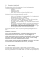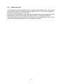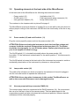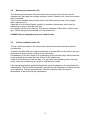
1
MicroDancer Infrared Vortex Evaporator User Manual English - Version 2.1 Seestrasse 204a, CH-8806 Bäch / SZ , Switzerland Tel. +41 44 786 80 20, Fax +41 44 786 80 21 E-mail: [email protected], Internet: http://www.hettich-ag.ch Content 1.0 Operating principle, installation and first steps 1.1 1.2 1.3 1.4 1.5 1.5.1 1.5.2 1.5.3 1.6 1.7 1.8 1.9 1.9.1 Operating principle Safety instructions Package contents Unpacking and setting up of the instrument The MicroDancer Infrared Vortex Evaporator Front view Back view The vacuum chamber Sample racks PoleStar cold trap Vacuum pump Installation of the MicroDancer ConnectingMicroDancer and PoleStar 4 5 7 7 8 8 9 10 11 11 13 13 13 2.0 2.1 2.2 2.3 2.4 2.5 2.6 Operating elements at the front side of the MicroDancer Release valve switch (1) Compartment heater switch (2) Heater switch – lid (3) Temperature controller (4) Shaker switch (5) Shaker speed (6) 14 14 14 14 15 16 16 3.0 3.1 3.2 3.3 3.4 3.5 Operating elements at the front side of the MicroDancer Power socket (10) and on/off switch (11) Lamp outlet socket (16) Vacuum pump/cold trap connector DN25 (14) Release gas connector (12) Lid fan (ventilation slots -13) 17 17 17 17 18 18 4.0 Working with the MicroDancer 19 4.1 Starting of an evaporation process 19 5.0 Cleaning 20 5.1 5.2 5.3 Cleaning of the housing Cleaning of the glass plate Cleaning of the vacuum chamber 20 20 20 2 4 Content 6.0 Maintenance and repair 21 6.1 6.2 Maintenance Repair 21 21 7.0 Spare parts 22 7.1 7.2 Spare parts list (electrical) Spare parts list (mechanical) 22 23 8.0 Device specifications 24 8.1 Infrared spectrum 25 Annex EC Conformity Declaration 26 3 1.0 Operating principle, installation and first steps 1.1 Operating principle Thank you for choosing the MicroDancer Infrared Vortex Evaporator. This device has been designed to suit the most demanding requirements and to ensure the highest flexibility for the evaporation of solvents using various types of sample tubes, microtiter- or deepwell plates. The MicroDancer can be also used as reaction chamber, incubator or as vacuum dryer. The operating principle is a combination of heating, vortex and vacuum. These parameters can be manually defined. The MicroDancer can accommodate 2 deepwell plates or microtiter plates. Special racks can also accommodate HPLC-vials or other larger containers, such as Falcon tubes for instance. The vacuum can be adjusted using a diaphragm pump or a rotary vane pump. Infrared lamps located in the lid heat the samples. An independent compartment heater prevents the condensation of solvents with high boiling point in the vacuum chamber. The actual temperature can be measured directly in the sample or in the rack (recommended) by means of a PTFE-coated temperature sensor. There are no rotating parts in the MicroDancer. Vortex of samples is achieved by means of a magnetic drive. No balancing of the samples is required. An evaporating system consists of the MicroDancer, the PoleStar cold trap and the Vacuubrand PC3003 VARIO pump, which opens you a nearly unbounded flexibility. So, it is possible to program time-dependent short and long term vacuum gradients which leads to an extremely verifiable and reproducible evaporation of solvents. Due to its unbeatable price-performance ratio, the MicroDancer will amortize itself shortly. Time saving and efficiency of the instrument will give you a real competitive advantage. 4 1.2 Safety instructions The MicroDancer Infrared Vortex Evaporator is a state of the art, reliable product; however, it may lead to hazards for the user or a third party if it is not used by trained personnel, if used improperly, or if the user does not observe instructions. Operating instructions of the MicroDancer must be read and observed before the device is put into operation Besides operating instructions and regulations regarding prevention of accidents, the universally recognized technical standards for safe working conditions have to be observed at all times. In addition to the operating instructions, the current national regulations concerning prevention of accidents and environmental care also have to be observed Only connect devices to a grounded electrical outlet, using power cords corresponding to the instructions. Never use damaged cables. Damaged or insufficient grounding involves danger of life Attention must be paid to the instructions concerning AC power and power consumption When the MicroDancer is transferred from a cold place to the laboratory, condensation may appear in the device. In such a case, allow it to acclimatize for at least two hours before operating Attention must be paid to allowable ambient operating temperature and to air supply, especially during mounting of the device A vacuum is generated by the vacuum pump during solvent evaporation. Observe safety rules to generate and measure vacuum. Operating instructions of the utilized vacuum pump also have to be observed Carry thermal insulated gloves and a laboratory coat with long sleeves, when reaching into the instrument. (Danger of being burnt, when touching the chamber surface at high evaporating temperatures) Only qualified personnel, which has been trained by Hettich AG Switzerland is authorized to service this equipment. Use only genuine parts and accessories. The use of components from another manufacturer may affect the functionality i.e. the safety of the device and its electromagnetic compatibility When using non-original sample racks or spare parts (self-made or nonHettich AG products) the warranty will expire immediately! Do not place any solvent container or any objects on the MicroDancer 5 The coolant circuit of the PoleStar cold trap is maintenance-free. A qualified refrigeration specialist should be the only person authorized to remove errors if any should appear Please read always the material safety data sheet (MSDS) of the medium, which should be evaporated. Please check, that the flash point and the point of ignition will not be reached or even exceeded (danger of explosion!) Place the temperature sensor always in the destined borehole in the sample rack. It should never dangle outside the instrument Never cover the instrument with cloths or other coverage (fire hazard!) IMPORTANT: Hettich AG Switzerland will assume NO liability for any improper use of the instrument 6 1.3 Package contents Now please take the MicroDancer and its accessories out of the box. The package contents: 1x MicroDancer Infrared Vortex Evaporator 1x shaker plate with three rotary feet 1x power cord 1x operation manual Should one of the above listed items be missing, please contact the manufacturer or your reseller. 1.4 Unpacking and setting up of the instrument Unpack and inspect the MicroDancer carefully. The package contents the shaker plate, the country-specific power cord and the instruction manual. Place the MicroDancer on a stable basis or work bench. Leave enough space behind the instrument, so that the cover with the lamp assembly can be completely opened. The space behind the instrument is also necessary to allow a sufficient circulation of air to avoid overheating of the instrument. Now open the cover with the lamp assembly and remove all packing material or other foreign materials form the vacuum chamber. Especially check the big boreholes, which are used to place the feet of the shaking plate, for any metallic of glassy particles. They easily can damage the glass plate and leads to high cost of repair. Now place the shaker plate with the rack in the vacuum chamber. The rotary feet will be placed in the designed boreholes. Now place the temperature sensor in the small borehole at the rack. Please take care, that the temperature sensor will not be clamped or bent . Now you can close the cover. Your MicroDancer can now be connected. This is described in chapter 1.5. 7 1.5 The MicroDancer Infrared Vortex Evaporator 1.5.1 Front view Picture A shows the front view of the MicroDancer. 9 8 7 1 2 3 4 6 5 Picture A: Front view of the MicroDancer 1 2 3 4 5 Release valve switch Compartment heater switch Heater switch for lamp Temperature controller Shaker switch 6 7 8 9 Speed potentiometer Handle to open the lid Viewing window Lid Picture A shows the front view of the MicroDancer. The Lid of the instrument (9) can be opened upwards with the handle (7). The front plate contains the control elements (1) to (6). The temperature controller (4) allows to adjust the temperature set point for the evaporation and to control the actual temperature. A detailed description follows in chapter 2.4 . The viewing window (8) allows to inspect the samples during the evaporation process. 8 1.5.2 Back view Picture B shows the back view of the MicroDancer. The provided power cord must be plugged into the socket (10). Switch (11) allows to turn the MicroDancer on or off. 11 10 16 12 14 13 15 Picture B: MicroDancer back view 10 11 12 13 Mains power in socket On/Off switch Inert gas hose adaptor (6mm ID) Ventilation slots 14 Cold trap / vacuum pump DN25 connector 15 Specification label 16 Lamp output socket A fan is placed behind the ventilation slots in the instrument lid (13). To aerate the vacuum chamber with inert gas a 6mm ID Teflon tube can be connected at the inlet gas hose adaptor (12). The cold trap respectively the vacuum pump will be connected at the DN25 connector (14). Inside-centred and outside-centred DN25 gaskets can be used comparably. We recommend inside-centred DN25 gaskets. The specification label (15) shows serial number, year of production, supply voltage, maximum power consumption of electricity of the instrument. The cable of the infrared lamp assembly is connected to the mains in power socket (16). 9 1.5.3 The vacuum chamber Lift the lid (9) of the MicroDancer at the black handle (7) to get access to the vacuum chamber (19). Picture C shows the open vacuum chamber. 18 19 16 20 17 21 Picture C: Vacuum chamber insight 16 500W infrared rod 17 Temperature sensor PT-100 18 Borosilicate glass plate 19 Vacuum chamber 20 Sample rack 21 Release gas inlet There are three circular holes at the bottom of the vacuum chamber (19) to fix the rack mounted at the shaker plate (20). Clean these holes weekly to avoid unnecessary abrasion of the shaker plate. The temperature sensor (17) allows to measure the temperature of the samples respectively of the rack. The Hettich sample racks have a capable borehole to place the temperature sensor correctly. Please note, that the lid can not be opened manually, even with high effort, when there is a vacuum generated in the vacuum chamber. The assembly of a sample rack is shown in chapter 1.6. 10 1.6 Sample racks There are various sample racks that can be chosen to work with the MicroDancer. All racks have the same shaker plate, on which different stands for sample container can be mounted. Picture D shows the universal rack with test tubes. Sample racks are made of anodised aluminium and exist for almost all common sample containers. The shaker plate can accommodate up to 2 deepwell- or microtiter plates. The correct functionality can be only guaranteed, when original Hettich racks are used. When using self-made racks the warranty for the shaker plate and the drive mechanism of the MicroDancer will expire immediately! Picture D: Universal rack with test tubes. Sample racks can be customised to fit your specific containers or container combination. Picture E shows the shaker plate with rotary PTFE/C feet. Picture E: Shaker plate with rotary PTFE/C feet. 11 1.7 PoleStar cold trap Picture F shows the PoleStar cold trap from the front. It has a three-litre capacity. The back view of the instrument is shown in picture G. Power switch 28 turns the unit on or off. Press the defrost switch (23) to defrost frozen solvents. The window (26) allows to see the cooling coil in the FEB coated vessel on which the solvent condensates and freezes. The temperature display (22) indicates the actual temperature in the cold trap. The MicroDancer will be connected with a DN25 tube connector (24) The vacuum pump will be connected at port (25). You also can see the drain valve (27) used for draining condensed solvent (press or pull). 24 25 26 22 27 23 Picture F: PoleStar Cold Trap (front view) 22 Temperature display 23 Defrost mode switch 24 DN25 Connector to MicroDancer 25 Tube connector to vacuum pump (ø10mm) 26 Cold trap window 27 Drain valve 28 30 29 Picture G: PoleStar Cold Trap (back view) 28 Power switch 29 Mains power in socket 30 Power out socket (for Vacuubrand PC3003/3004 VARIO pump) 12 1.8 Vacuum pump The MicroDancer works in combination with diaphragm pumps as well as rotary vane pumps. The use of Vacuubrand PC3003/3004 VARIO diaphragm pump allows to program time-controlled gradients. This allows to evaporate even difficult solvent gently. Note: 1.9 Vacuubrand PC3003 VARIO diaphragm pump produces a maximum vacuum of 0,6 mbar. This is sufficient even to evaporate high-boiling point solvents. Rotary vane pumps, which are however uncontrolled can also be used as stand alone units to generate vacuum. Installation of the MicroDancer To install the MicroDancer an additional vacuum pump is required, and optionally a cold trap. The following data refer to pictures B (page 9) and F (page 12), which shows the back of the different devices MicroDancer and PoleStar cold trap. Please refer to the manual delivered with the pump for information about its connection. 1.9.1 Connecting MicroDancer and PoleStar On the MicroDancer Evaporator (Picture B) • Place the MicroDancer on a horizontal surface. • Plug the country-specific power cord into the mains power inlet socket (10). • Connect, if available the cold trap respectively the vacuum pump to the DN25 vacuum connector (14). • If required, connect the inert gas (nitrogen, helium) hose with integrated pressure reduction valve to connector (12). On the PoleStar cold trap (Picture F) • Place the PoleStar cold trap under the table close to the MicroDancer. • Plug the power cord into the mains power inlet socket (29). • Place one end of the power cord of the Vacuubrand PC-3003/3004 VARIO pump in the power outlet socket (30) and the other end in the mains power inlet socket of the vacuum pump (see pump instruction manual). • Connect the vacuum tube of the MicroDancer at DN25 connector (24). • Connect the tube form the vacuum pump (ø 10mm ) at the tube connector (25). The devices can now be turned on and off in any order. The release valve opens automatically in case of a power failure. Therefore the access to the samples is assured. 13 2.0 Operating elements at the front side of the MicroDancer The operating elements of the MicroDancer allow the manual settings of all parameters required for the evaporation process and to switch on and off these actuators. Therefore read the following explanations carefully. The explanations and the numbers in chapters refer to picture A at page 8. 2.1 Release valve switch(1) The release valve switch (1) closes the air inlet vent at the backside of the instrument before the start of the evaporation process. Also it opens the air inlet vent at the end of the evaporation process. It is a NO (normally open) needle valve, which opens in current less state automatically. It allows the inflow of atmospheric air or of inert gas, depending on the application used. The release valve should not be opened during the evaporation process, because the rapid inflow of air can cause a loss of solvent or dissolved sample. 2.2 Compartment heater switch (2) The compartment heater switch (2) allows to activate and deactivate the compartment heater of the vacuum chamber. The compartment heater avoids the condensation of solvent vapour at the cold wall of the vacuum chamber. The heating is controlled by a thermostat and has a temperature of 60° Celsius +/- 5°C. ATTENTION: Do not touch the compartment heater wall – burn hazard! Therefore it is not allowed to activate the vacuum chamber heater for the evaporation of highly volatile solvents, for example ether, benzene or similar solvents, because the high temperature can cause the combustion of the solvent. Please check the material safety data sheet (MSDS) of the solvent and decide it he vacuum chamber heater is useful for your application. 2.3 Heater switch for infrared rod (3) The heater switch (3) allows to activate and deactivate the infrared rod at the inside of the lid. This heater compensates the temperature loss of the sample during the evaporation process. The temperature can be adjusted at the temperature controller (4).This will be explained in chapter 2.4. 14 2.4 Temperature Controller (4) The temperature controller (4) allows to adjust the set point temperature. The following components act conjoined: - Controller - Infrared rod in the lid - Temperature sensor - Heater switch (activation or deactivation of the heater) Adjustment of the set point temperature at the controller: - Switch on the MicroDancer at the power switch (11) at the backside of the instrument (see picture B at page 9). Wait until the initialisation process is finished. If the instrument is already switched on, continue with the next step Now press the button “P” at the temperature controller. The display shows the description “SP” followed by the actual set point temperature. Now press the arrow keys to define the required set point temperature. The temperature changes 0.1°C with every short keystroke. A long keystroke allows a rapid change of the temperature setting. After the correct set point temperature entry press the button “P” again. Now the display shows the actual value of the temperature. The set point temperature can be changed at any time by pressing the button “P” again. ATTENTION: burn hazard! The use of the infrared lamps in the compartment lid may generate high temperatures, which can cause severe burns when opening the lid. Use the infrared lamps extremely careful for the evaporation of highly volatile solvents, for example Ether, benzene or similar solvents, because the high temperature can cause the combustion of the solvent!! Please check the material safety data sheet (MSDS) of the solvent and decide if it is recommended to use the infrared lamps to heat your sample. 2.5 Shaker switch (5) The shaker switch allows to activate or deactivate the motor of the shaker. The speed can be adjusted with a 10-gear rotary potentiometer. If the selected value at the rotary potentiometer is too low, the shaker may not be active (see chapter 2.6). 15 2.6 Shaker speed (6) The rotary speed can be adjusted with the 10-gear rotary potentiometer. The shaking process starts, when the selected value exceeds 3.0 to 3.5 . The maximum value is 10.0 with a shaking speed of 1,000 rpm. Please note, that the display of the rotary potentiometer does not corresponds to the actual shaking speed, for example the entry 9.0 does not comply with 900 rpm. The shaker can be switched off without turning the rotary potentiometer. So you can keep the desired shaking speed for you evaporation process. 16 3.0 Operating elements at the back side of the MicroDancer At the back side of the MicroDancer the following elements are located: - Power socket (10) - On/Off switch (11) - Inert gas hose adaptor (12) - Ventilation slots (13) Cold trap/vacuum pump connector (14) Lamp outlet socket (16) The numbers in the chapters refer to picture B at page 9. The MicroDancer requires a distance of at least 30 cm to the wall or the next device to allow a proper cooling of the instrument. NEVER limit the functionality of the fan in any way! 3.1 Power socket (10) and on/off switch (11) Plug the country-specific power cord into the power socket (19). ATTENTION: Before activating the instrument check the local line voltage and compare it with the required voltage printed at the type plate (15). The feeder should be fused properly. In case of doubts please contact your electrician our your local supplier of electric energy. The On/Off switch (11) is located horizontally above the power socket (10). In position “O” the instrument is deactivated. In the switch position “I” the instrument is turned on. The On/Off switch is located at the back side of the instrument on purpose to avoid an accidentally deactivation of the instrument by cleaners or other persons. 3.2 Lamp outlet socket (16) The cable of the infrared rod, which is located in the instrument lid must be plugged into the rod outlet socket to operate the infrared rod. ATTENTION: Never plug other instruments in this socket. The MicroDancer as well as the connected instrument can be damaged heavily! 3.3 Vacuum pump/cold trap connector DN25 (14) The vacuum pump has to be connected at the DN25 connector (14). We recommend the use of a cold trap in front of the vacuum pump. This has advantages for the evaporation process and also minimizes the environment pollution, because harmful substances will be collected properly. 17 3.4 Release gas connector (12) The release gas connector allows to connect an inert gas line to fill the vacuum chamber with inert gas (for example nitrogen, helium) instead of air, when the vacuum will be released. This is recommended, when solvent with a low flash point are used ( for example ether, benzene etc.). Open the lid of the MicroDancer carefully to minimize turbulences, which can be created by mixing air with the inert gas. As nitrogen is more heavy than air, the vacuum chamber is filled with a “lake of inert gas”. So the samples are shielded from the ambient air. ALWAYS use an adjustable pressure control valve. 3.5 Lid fan ventilation slots (13) The fan, which is located in the lid cools the infrared lamp and extends its lifetime considerably. Therefore the MicroDancer requires a distance of at least 30cm to the wall or the next instrument to allow a proper cooling of the instrument. A breakdown of the fan results in an overheating of the infrared lamp, which heats the lid excessively and causes the early failure of the infrared rod. Check the functionality of the fan daily. You can listen the operating noise of the fan easily, when the infrared rod is turned on and the lid is closed. If the set up temperature should be below the actual temperature, do not activate the infrared lamp. The fan does not operate, when the actual temperature is below the set up temperature. The fan operates even if the lid is opened, when the actual temperature is above the set up temperature. 18 4.0 Working with the MicroDancer 4.1 Starting of an evaporation process The different operating elements have been discussed in chapter 2 and 3. This chapter will give a short introduction how to start an evaporation process: - Power on the vacuum pump and the cold trap Switch on the MicroDancer at the On/Off switch at the backside (left) The temperature controller initialises Open the lid of the instrument Insert the rack with the test vials in the vacuum chamber Place the temperature sensor in the small borehole in the rack close to the sample vials Close the instrument lid Enter the set up temperature at the temperature controller (see chapter 2.4) Press the release valve switch to close the release valve Switch on the shaker by pressing the shaker switch to start the shaker motor Now turn the rotary potentiometer to adjust the desired shaking speed Switch on the compartment heater by pressing the compartment heater switch, if required for your application Switch on the heater switch to activate the infrared lamp if required for your application The MicroDancer now starts to heat up your samples Switch on your vacuum pump Example for Vacuubrand PC3003 VARIO pump: • • • • • • • • Press the „Mode“ key Turn the control dial until the display shows „Automatic“ Press the control dial to select the function Turn the control dial until the display shows “back” Press the control dial to select the function The display now shows the pressure bar with the header “Automatic” Press the start/stop key The pump starts to operate 19 5.0 Cleaning As every laboratory instrument, the MicroDancer also requires regular maintenance. This chapter will give you useful hints for cleaning and maintenance of your MicroDancer. Damages, caused by improper cleaning and maintenance are not covered by the instrument warranty. 5.1 Cleaning of the housing Clean the housing with a cloth, which is gently wetted with water. For stronger contamination use a mild detergent. Never use solvent-containing cleaning agents, for example acetone etc. 5.2 Cleaning of the glass plate The glass plate can be cleaned with a glass cleaning agent of good marketable quality. For compete cleaning gently remove the glass plate from the lid. Remove the four upper screws at the side of the lid (2 screws at the left hand side and 2 screws at the right hand side), when the lid is closed. After removal of the screws open the lid. The glass plate stays at the gasket of the vacuum chamber. Now remove the glass plate and place it on a clean support. Now remove the dirt from both sides. Then place the glass plate at the gasket. The holders of the glass plate contain guide pins, which can be adjusted at the lamp holder bracket. Guide the glass plate with one hand and fix the screws preliminary with the other hand in the glass holder. Then close the lid carefully and tighten the screws stoutly with a 3mm hexagon socket screw key. 5.3 Cleaning of the vacuum chamber The cleaning of the vacuum chamber requires particular attention, because the deep holes for the feet can be filled with grit, dust, metal particles or even culets. Therefore the holes must be weekly controlled and cleaned. Remove them as efficient as possible to assure the proper functioning of the shaker. As cleaning agent we recommend ethanol 70%. 20 6.0. Maintenance & Repair 6.1 Maintenance Maintenance should be only carried out by an authorized distributor or a service technician, trained from Hettich AG Switzerland. The annual maintenance service contains the following checks: 1. 2. 3. 4. 5. 6. 7. 8. 9. 10. Cleaning of the instrument Check of the temperature sensor and exchange if applicable Check of the drive belt and exchange if applicable Calibration of revolution speed Temperature measurement upon request (Qualification against surcharge) Check of O-rings and exchange if applicable Electrical operational test Country-specific safety check according EN61010 Leakage test System check upon request (against surcharge) Please ask you distributor for a service contract. He will give advice and submit you an offer. 6.2 Repair The MicroDancer was developed and designed for utmost reliability. Nevertheless failures during operation can happen. In this case disconnect your instrument immediately and contact Hettich AG Switzerland or your specialist dealer. Tell him always the type of instrument, the serial number and the kind of problem you have. It is always helpful to know, when the problem happens, for example during switch-on or during the operation. Example: Problem with MicroDancer, serial number 400003, the shaker does not operate. The fault happens during operation. This helps the service technician to localize, or even to solve the problem. 21 7.0 Spare parts 7.1 Spare parts list (electrical) Articl No. Description CD.E201 CD.E202 MD.E203 MD.E206 MD.E210 MD.E212 MD.E214 MD.E215 MD.E216 IRD.E218 IRD.E219 MD.E221 MD.E222 MD.E223 MD.E228 MD.E229 MD.E232 MD.E233 MD.E235 MD.E245 MD.E246 MD.E247 MD.E248 MD.E252 MD.E253 Infrared rod 235V 500W R7s Temperature sensor PT100 Release valve (complete) Temperature Controller Jumo (controller) Fan 230VAC (top cover) Compartment heater Mains power inlet/ circuit breaker (power in) Power outlet socket (lamp out) Fuse T5A L (power input 230V) Potentiometer (shaker) Analogue adjusting knob with bracket (shaker) Switch 230VAC two-pole red (heater) Switch 230VAC two-pole green (shaker) Switch 230VAC two-pole amber (valves) Power cord L-N-PE (cover) Cable clip holder Electronic main board “Print power supply” Thermostat 60°C ( lamp housing) Bracket R7s Thermostat 60°C (compartment heater) Thermostat 80°C with RESET (compartment heater) Fan 115VAC (top cover, USA/Japan version) Tilt switch (Safety switch including isolator to cover) Shaker motor (shaker) FuseT10A L (USA/Japan version) 22 7.2 Spare parts (mechanical) Article No. Description MD.M103 MD.M109 MD.M111 MD.M114 MD.M117 MD.M118 MD.M120 MD.M122 MD.M125 MD.M127 MD.M128 MD.M129 MD.M131 MD.M132 MD.M133 MD.M134 MD.M135 MD.M139 MD.M146 MD.M147 MD.M149 MD.M156 MD.M157 MD.M165 MD.M169 IRD.M170 Silcoflon O-Ring red 304.10x7.0mm (vacuum chamber sealing) Transmission belt (drive assembly) Device feet (4 pieces) Drive assembly (complete) Gauge-glass (lid) Borosilicate glass complete Vacuum chamber 1/8” Fitting (vacuum chamber) Wire mesh (including gasket) Teflon tubing d=6mm (for gas Inlet) Spacer (for electronic main board) Handle (for lamp cover) Barb fittings, 2 pieces (part of article no MD.E203: contains 2x pieces) Erection bolt, 2 pieces (part of article no MD.E203: contains 2x pieces) Blank holder for Gauge-glass (vacuum chamber) Front cover (empty) Top cover Lid complete (without borosilicate glass MD.M118) Cover plate (belongs to lamp cover) Hinge left complete Hinge right complete Vacuum adapter DN25 Gas spring strut (Cushion for glass plate ) Silcoflon O-Ring 50.39x3.53mm, set of 3 pieces (for shaker plate) 23 8.0 Device specifications MicroDancer: Dimensions Width: Depth: Height: Weight: Power source: Fuses: Power consumption total: Power consumption of IR-rod: Power consumption of compartment heater: Power consumption of shaker motor: Power consumption of release valve: Power consumption of Jumo temperature controller: Power consumption of LED chamber light Vortex rate: Control: Temperature range of heater (infrared lamp): Temperature range of compartment heater: Safety shutdown compartment heater: Safety shutdown infrared lamp: Temperature sensor: Vacuum connector: Connector for release / inert gas: Vacuum Chamber Material: Diameter: Height: Material of front plate: Material of base plate, cover holder: Material of top, lid side/upper part: Maximum loading of shaking plate total: Maximum loading of shaking plate total: Maximum length of test tube: 448 mm 530 mm (lid closed) 609 mm (lid opened) 393 mm (lid closed) 700 mm (lid opened) 50 kg net without base plate 230VAC 50/60 Hz 100V-115VAC 50/60 Hz upon request 2x T5A/L glass tube fuse 5x20mm 963 VA 500VA 400VA 50VA 10VA 3VA 3VA 40 – 1.000RPM +/- 5% 10-gear rotary potentiometer room temperature (20°C) to 80°C 60°C +/- 5°C 80°C with manually reset* 80°C with automatically reset PT-100 with PTFE protective cover DN25 6mm tube connector (synthetic) Stainless steel V2A 300 mm 150 mm V0 plastic UL-listed Galvanized steel Aluminum powder-coated 3000g (shaking rate below 300rpm) 1500g (at maximum speed) 120mm PoleStar: Dimensions Width: Depth: Height: Weight: Power Source: 520 mm 430 mm 530 mm (without tubing) ca. 45 kg 230VAC 50/60 Hz 100V-115VAC 50/60 Hz upon request 660 VA (3.15A) 3.3 Litre - 45°C +/- 5°C (idling) Power consumption: Capacity: Cooling temperature: Material Chamber: Cooling coil: Gas inlet- / outlet: Tope cover, base plate: Back cover: Aluminum FEP coated V4A stainless steel, FEP coated PTFE, connectors V4A steel V2A stainless steel Aluminum * Requires removal of front plate! 24 8.1 Infrared spectrum The figure below shows the characteristics of the IR emission of the infrared rod (2400K curve). In case of a rod exchange, the new lamp should NEVER be touched directly with fingers. Always use a lint-free cloth! 25 26