1
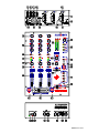
AVIS: RISQUE DE CHOC ELECTRIQUE - NE PAS OUVRIR.
D R S D IG ITAL R EC ALL S YS TEM
100 - 240V~
47-63Hz ~ 30W MAX
P
R
O
F
E
S
S
I
O
N
A
L
P
R
O
F
E
S
S
I
O
N
A
L
D J
D
J
M
M
I
I
X
X
E
E
R
R
XONE:32 User Guide
Connectors and Panel Controls
1
LINE input 2x RCA phono. Connect stereo line level music sources such as CD, MD, DAT, drum
machines, keyboards or other instruments. Do not connect turntables which require RIAA equalisation.
2 PHONO input 2x RCA phono. Plug in turntables with magnetic cartridges requiring RIAA equalisation.
For non-RIAA turntables plug into the LINE input instead. Do not plug in line level sources to the phono inputs
as these will overload the preamp and cause severe high level distortion.
3
CHASSIS earth A screw terminal is provided for connecting the earth straps from turntables. This
connection earths the metal parts of the turntable to reduce hum, buzz or similar audible noise getting into the
system. Make sure the terminal is fully tightened once the strap is in place.
4 INPUT SELECT switch Selects either the LINE input or the PHONO input as the source to the channel.
Press for PHONO, release for LINE. The select switches are positioned on the rear panel to prevent accidental
operation during performance.
5 INPUT LEVEL trim Rotary control to adjust the input gain to match the connected source to the console
operating level. Adjusts from fully off to +15dB gain. Use the channel meter 16 to ensure the trim is correctly
set for best performance. The trims are positioned on the rear panel so that they are protected from accidental
operation once set.
6 RECORD output 2x RCA phono. This provides a line level stereo mix output not affected by the main
mix master control. Connect to a stereo recorder such as MD, DAT or cassette to record the DJ’s set.
7 AUX output 2x TRS jack. Provides a line level stereo output independently mixed from the channel AUX
sends 13 . You can use this to feed samplers and other effects units, an additional monitor, zone or recorder.
The output is impedance balanced so it can connect to balanced or unbalanced equipment.
8 BOOTH output 2x TRS jack. This is the stereo output that feeds the DJ’s local booth monitor system. It
has its own level control and is not affected by the main mix master control or the cue mix. The output is
impedance balanced so it can connect to balanced or unbalanced equipment.
9
MIX output 2x TRS jack. This is the main stereo output that feeds the house PA. The output is
electronically balanced so it can drive long cable runs to balanced equipment without interference pickup. It can
also be wired to connect to unbalanced equipment.
10 MAINS input IEC socket. Plug the AC mains supply in here. A country dependent mains lead with
moulded plug is provided with the console. Ensure the local mains voltage is within the range specified on
the panel and that the connection is correctly grounded.
11 FUSE This is the mains input protection fuse for the internal power supply. In the unlikely event of it
failing make sure you replace it with the same type and rating. If the replacement fails get the console checked
by your service agent.
12 POWER ON switch Turns the console on or off. To avoid loud thumps or damage to your speakers
always turn amplifiers off before turning the console or other equipment in the signal chain on or off. Turn
amplifiers on last and off first.
13 AUX SEND control Adjusts the level of the channel signal to the stereo Aux output. It is taken ‘post-fade’
which means that the channel fader affects the level sent to the aux control. Turn fully anticlockwise to turn the
signal off, fully clockwise for a maximum +6dB boost. The normal ‘0’ position is marked.
14 Channel EQ The equaliser has three controls to let the DJ creatively alter and shape the sound during
live performance. The music frequency spectrum is divided into 3 bands. HI (10kHZ) has a shelving response
and affects the high frequency (treble) sounds, MID (1kHz) has a peak/dip bell shaped response and affects mid
range (presence) sounds, and LO (100Hz) has a peak/dip bell shaped response and affects low (bass) sounds.
This type of equaliser is known as ‘asymmetric’ because the amount of boost and cut is not the same. Boost is
restricted to a safe +6dB to highlight selected sounds while preventing system overload through heavy use. Cut
on the other hand, is increased to a huge –26dB to completely suck out affected frequencies dramatically
changing the effect. Use cut rather than boost to create your dramatic performance effects.
15 CUE switch Press this momentary switch to listen to the channel signal in the headphones. The three
switches are interlocked so that pressing one or more cancels the previous. The LED illuminates so that you
can see at a glance which channel is cued. A cue selection is always active. Switch on default is CH1 cue
selected. You can preview the mix using the CUE/MIX slider 32 . Cue does not affect the house mix or booth
speakers and lets you check the signal or cue a track before bringing it into the mix. Cue is pre-fader and postEQ so that you can preview and experiment with the EQ effects before going live.
16 Channel METER A 4 LED meter bar always shows the presence of the pre-fader channel signal. Adjust
the level trim control for normal music averaging 0dB with loudest moments reaching +5. Reduce the trim if the
red PEAK LED flashes consistently. The PEAK LED lights at +8dB to warn that you are within 12dB of clipping.
Letting the signal clip will result in a harsh distorted sound that can damage the speakers and is very unpleasant
for the listener. A good DJ will not let this happen.
XONE:32 User Guide
17 BALANCE control Adjusts the balance between the channel left and right stereo signals. Each side
ranges from fully off to fully on. The control has unity gain in the centre equal position and +2dB boost when
fully panned to one side. It is typically used for performance effect.
18 FILTER ON switch Press this momentary switch to route the channel through the filter stage for amazing
analogue VCF (voltage controlled filter) effects. The blue LED lights when the VCF is enabled for the channel.
The state of the switch is stored and recalled by the DRS™ presets.
19 Channel FADER A high grade 60mm stereo fader adjusts the channel signal level from off to the normal
‘0’ top position. It allows smooth fade ins and quick action live performance level effects. CH1 fader routes the
signal to the X side of the crossfader. CH3 routes the signal to the Y side of the crossfader. CH2 does not
route through the crossfader. The fader also affects the AUX sends 13 .
20 CROSSFADER The crossfader lets you smoothly fade from one track into another using a single fader.
It is also used as a creative performance tool to layer or interact between two sounds when cut or scratch
mixing. It can be easily replaced if it becomes damaged or worn through exceptional mechanical operation.
Long life is assured as the XONE:32 uses a high quality dual rail gold contact crossfade type together with VCA
circuitry which means that no audio is passed through the fader itself. CH1 routes to X, CH3 routes to Y, CH2
does not route through the crossfader. The response of the crossfader can be adjusted to match your mixing
style using the CONTOUR and REVERSE controls 35 .
21
TRANSMUTE buttons
The XONE:32 introduces this unique function which combines the familiar
‘transform’ and ‘punch’ DJ effects with an intelligence that opens up a new world of creative live performance
effects. The function of the button depends on the position of the crossfader. TRANSMUTE becomes a
transform button when the crossfade has moved away from the opposite side. It acts as a momentary action
mute that turns the signal off while the button is held. TRANSMUTE becomes a punch button when the
crossfader is right at the opposite side playing the other track. Here it punches the signal in (turns it on) on top
of the other track. For example, the CH1 track may be playing… Pressing X TRANSMUTE transforms (mutes)
that track, and pressing Y TRANSMUTE punches the CH3 track over the CH1 track.
22 VCF Filter Type Select Press one or any combination of the three momentary press buttons to select the
VCF response type. Default on power up is LPF (low pass filter) which cuts off all frequencies above the
selected frequency. Alternatively, you can select BPF (band pass filter) to cut off frequencies above and below,
or HPF (high pass filter) to cut off frequencies below, or press two or three buttons together to create different
effects. One or more types is always selected. The associated LED indicator is illuminated. The selected type
is stored and recalled by the DRS™ presets.
23 RESONANCE control Adjust this to change the ‘Q’ or ‘sharpness’ of the filters. This affects how they
respond around the cut-off frequency. At the minimum MILD setting the filters have a gentle roll-off ‘knee’ giving
a subtle, smooth response. At the clockwise WILD setting they produce a resonant feedback boost around cutoff resulting in some very dramatic performance effects. The sound varies according to the filter type selected.
To avoid unexpected results it is best to start experimenting with RESONANCE set to a low (mild) position.
24 LFO ON switch Press this momentary switch to let the LFO (low frequency oscillator) take over control of
the VCF by modulating its cut-off frequency. The LED indicator always flashes green to display the currently set
speed. It turns red when the LFO is switched in and continues to flash green to indicate speed. The VCF
FREQUENCY slider 28 changes function to become a depth control to determine how much modulation is
applied. The state of this switch is stored and recalled by the DRS™ presets.
25 x2 switch Doubles the speed of the LFO as set by tapping in the tempo. This lets you tap in the beat of
the track and create a double modulation per beat. The state of this switch is stored and recalled by the DRS™
presets.
26 TAP TEMPO button Tap this button with your finger to set the speed of the LFO. It automatically follows
your beat after two or three taps. You can double the speed by pressing the x2 switch 25 .
27 FILTER RECALL (DRS™ presets) This feature unique to Allen & Heath provides 4 preset buttons which
lets you store and recall your favourite VCF performance settings. This lets you punch in sophisticated filter
effects changes. When you first turn the console on there are no presets stored or recalled. Press and hold
one of the preset buttons for longer than 2 seconds to store the current settings into that memory. Tap the
button during performance to instantly recall that preset. The presets do not store the VCF resonance,
frequency, LFO depth or speed. The parameters stored include:
•
CH1-3 FILTER ON switch – Which channels have the VCF enabled
•
VCF type – Which combination of HPF, BPF and LPF is active
•
LFO ON switch – Whether the VCF is manually controlled or modulated by the LFO
•
LFO x2 switch – Whether the LFO speed is 1x or 2x the current speed
XONE:32 User Guide
28 VCF control slider This is a performance control ‘played’ by the DJ to create live effects in a similar way
to using the crossfader. Its function depends on whether the LFO is switched on or off. If the LFO is off then
the slider lets you manually set the cut-off frequency of the filter from a very low 100Hz to ultra high 20kHz. If
the LFO is switched on then the slider becomes a depth control for the LFO letting you adjust how much the
LFO modulates the filter cut-off frequency. Depth is off when the slider is fully right. Maximum effect is fully left
as the DJ pulls the slider in towards the other performance controls.
29 MAIN MIX MASTER control A rotary master control adjusts the output level feeding the house PA. This
is a stereo control which adjusts the left and right signals at the same time. It affects the stereo MIX output.
Note that it does not affect the record and booth outputs. The maximum position represents unity (0dB) gain. If
you find yourself normally setting the control in the lower part of its travel then the connected equipment may be
too sensitive for the operating level of the console. With the control set to its maximum position adjust the input
level trim of connected equipment for the loudest level allowed. In a club or similar installation strict sound
level and noise regulations may apply. Check that your system levels are set up to comply.
30 MAIN METERS A pair of LED meter bars displays the level of the MAIN MIX output. Each meter has 12
LEDs to indicate signal levels from a low –20dB. Green and yellow LEDs indicate normal operating levels. The
top red PEAK led lights at +8dB giving you plenty of warning that you are within 12dB of clipping. Meter ‘0’
represents +4dBu at the XLR outputs. The meters are peak responding with a fast attack and are therefore
able to display fast transients accurately. The top five LEDs are ‘peak hold’ which means that the highest
remains lit for a short time after the signal has gone. This makes it easier to keep track of the highest levels and
transient peaks. Do not operate the console with these meters lighting red more than the occasional
flash. Failure to observe this can result in severe signal distortion which may damage equipment.
31 BOOTH MASTER control Adjusts the level of the signal to the stereo booth monitor output. This does
not affect the level in the headphones.
32 CUE/MIX slider This affects what you hear in the headphones. When fully left, only the CUE signal is
routed. The CH1, 2 and 3 CUE switches are interlocked with a selection always active. When fully right, the
main MIX is routed so you hear only what is being sent to the house speakers. Move the slider between these
positions to mix the active CUE signal with the MIX. This not only lets you use the headphones to cue tracks
ready to bring them into the mix, but also accurately adjust point and tempo against the currently playing track
and preview how the mix will sound. You use this slider as a ‘crossfader’ to test the mix in your headphones
only. It does not affect the booth or house mix.
33 CROSSFADE OFF switch This front panel switch lets you disable the crossfader so that the channels
route directly to the main mix. The green LED lights when the crossfader is enabled.
34 CROSSFADE REVERSE switch Reverses the X and Y sides of the crossfader so that CH1 feeds Y and
CH3 feeds X. This better suits the mixing style of some DJ’s.
35 CROSSFADE CONTOUR control This adjusts the law of the crossfader from a gentle fade with 6dB dip
at centre position to a very sharp fade where full level is achieved just a few millimetres from the end stop. The
control can be adjusted to suit the DJ’s preference or mixing style.
36 HEADPHONES LEVEL control Adjusts the level of the signal in the stereo headphones. This does not
affect the level of the booth monitor. WARNING: Some headphones are more sensitive than others and
can produce higher output levels. To avoid damage to your hearing start with the level control at
minimum and turn up only as much as is needed to maintain comfortable listening level. Do not drive
headphones at high listening levels for long periods of time.
37
PHONES socket
This output is positioned on the front panel so that the DJ can plug favourite
headphones in without needing access to the rear. Headphones are available in many different styles,
impedances and volume ratings. To get the best from your system we recommend that you use high quality
closed-ear headphones around 70 ohms impedance, although 30 to 600 ohms will work. 8 Ohm headphones
are not recommended. Avoid using mini-jack to ¼” jack adapters as these may quickly prove unreliable.
38 MIC input Balanced XLR. Plug your DJ microphone in here if you choose to use one. It is best to use a
mic with integral on/off switch so that the DJ can turn it off when it is not being used. Use rugged, good quality
low impedance dynamic microphones such as those specifically designed for vocals. Do not use high
impedance or unbalanced microphones, or condenser types which require phantom power.
39 MIC GAIN control Adjusts the level of the microphone signal in the main mix from fully off to +45dB gain.
Start with the control set fully off (anticlockwise).
40 MIC EQ controls A 2 band EQ with shelving HI and LO controls provide +/-12dB of adjustment of the low
and high frequencies to suit the DJ’s microphone style. LO is set at 300Hz to help cut boominess or enhance
warmth, while HI is set at 5kHz to cut harshness or boost clarity and intelligibility over the mix. Avoid extreme
settings. Note that there is a built-in high pass filter which cuts very low frequency sounds such as popping and
mic handling noise.
XONE:32 User Guide