1
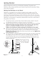
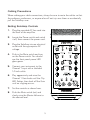
www.fishman.com
USER GUIDE
SOLOAMPTM
Whenever this symbol appears, it alerts you to the
presence of important operating and maintenance
(servicing) instructions in the user’s manual for this
amplifier.
Wherever this symbol appears, it alerts you to the
presence of uninsulated dangerous voltage inside
the enclosure that may be sufficient to constitute a
risk of shock.
CAUTION
Risk of electric shock.
Do not open.
No user serviceable parts inside.
Refer servicing to qualified personnel.
Do not expose to rain or moisture.
Important Safety Instructions
To ensure your personal safety and the safety of others, operate this apparatus only after reading these instructions
and heeding the warnings listed below.
1.
2.
3.
4.
5.
6.
7.
8.
9.
10.
11.
12.
13.
14.
15.
16.
17.
Read these instructions.
Keep these instructions.
Heed all warnings.
Follow all instructions.
Do not use this apparatus near water.
Clean only with a dry cloth.
Do not block the ventilation openings. Install in accordance with the manufacturer's instructions.
Do not install near any heat sources such as radiators, heat registers, stoves or other apparatus (including
amplifiers) that produce heat.
Do not defeat the safety purpose of the polarized or grounding-type plug. A polarized plug has two blades
with one wider than the other. A grounding-type plug has two blades and a third grounding prong. The
wide blade or the third prong are provided for your safety. If the provided plug does not fit into your outlet,
consult an electrician for replacement of the obsolete outlet.
Protect the power cord from being walked on or pinched, particularly at the plugs, convenience receptacles
and the point where they exit from the apparatus.
Use only attachments/accessories specified by the manufacturer.
Use only with a cart, stand, tripod, bracket or table specified by the manufacturer, or sold with the
apparatus. When a cart is used, use caution when moving the cart/apparatus combination to avoid injury
from tip-over.
Unplug this apparatus during lightning storms or when unused for long periods of time.
Refer all servicing to qualified service personnel. Servicing is required when the apparatus has been
damaged in any way, such as a power-supply cord or plug is damaged, liquid has been spilled or objects
have fallen into the apparatus, the apparatus has been exposed to rain or moisture, does not operate
normally, or has been dropped.
Do not expose the apparatus to dripping or splashing liquids and do not place objects filled with liquids
(such as a beverage container or a vase) on the apparatus.
Warning” To reduce the risk of fire or electric shock, do not expose this apparatus to moisture.
The apparatus should be connected to mains outliet with a protective earthing connection.
Disconnect device is Mains Plug, which should remain readily operable.
Copyright © 2008 FISHMAN TRANSDUCERS, INC.
All rights reserved. No part of this document may be reproduced in any form without the
written permission of FISHMAN TRANSDUCERS, INC.
2
Welcome
Thank you for making Fishman a part of your acoustic experience. We are proud
to offer the finest acoustic amplification products available; high-quality
professional-grade tools which empower you to sound your very best.
Before using your SoloAmp, carefully read the following sections:
Important Safety Instructions (Page 2)
Getting Started (Page 4 and 5)
Save Your Packing Materials
The box and packing materials for the SoloAmp were specially designed to protect the amplifier during shipping. Save all this stuff in case you need to re-ship
the SoloAmp.
Troubleshooting
Should you have any problems, please check with your installer or refer to the
online installation guide for this product. Technical support, troubleshooting tips
and installation information can be found at http://www.fishman.com/support/
Hear This!
The SoloAmp amplifier is capable of cleanly reproducing the sound of your
instrument at very high volume levels. Prolonged repeated exposure to high
sound pressure levels (SPLs) without protection can cause permanent hearing
loss. OSHA has set guidelines and specified permissible sound-exposure limits
for those who work in high SPL environments.
Permissible Noise Exposures
Duration per day, hours
8
6
4
3
2
1 1/2
1
1/2
1/4 or less
Sound level dBA slow response
90
92
95
97
100
102
105
110
115
To ensure against permanent hearing loss, wear hearing protection when you perform with
amplification.
SoloAmpTM
Tested to Comply
With FCC Standards
FOR HOME OR OFFICE USE
3
Getting Started
Here are some basic setup tips to help get you going. To operate your
SoloAmp safely, please read the entire manual, especially the Important Safety
Instructions on page 2.
Setting the SoloAmp on its Stand
SoloAmp is intended for use with the included tripod speaker stand. The
system is designed for use in portable applications where the amplifier and
stand are to be placed directly on a level, solid, flat surface. Do not substitute
the speaker stand with a non-Fishman part or attempt to mount or suspend the
SoloAmp in a permanent or temporary method other than that as described in
this guide or by Fishman.
1.
2.
3.
4.
Locate the stand in a place that is free of obstructions, where it may be
accidentally pushed over, or where it may be a trip hazard.
Loosen the lower of the two large thumbscrews and spread the tripod legs.
Follow the height warnings printed on the stand for safe operation
(Figure 1). Setting the height outside this area is forbidden.
Tighten the thumbscrew before placing the SoloAmp on the stand.
Remove the safety pin and loosen the top large thumbscrews. Extend the
top tube to the third hole or lower if you are seated while performing.
Replace the safety pin. Allow the tube to rest on this pin and tighten the
top thumbscrew (Figure 2).
Lift the SoloAmp using the handle on the back of the unit while supporting
the weight with your other hand. A guide is molded into the underside
of the SoloAmp and acts as an aid in positioning the SoloAmp onto the
tripod. Once positioned, lower the SoloAmp onto the tripod until it rests
firmly on the tube.
Warning: Follow the height warnings
printed on the stand for safe
operation. Setting the height outside
this area is forbidden.
Loosen
Tighten
Max. stand diameter: 38.6inches / 980.9mm
Figure 1.
Figure 2.
4
Safety Pin
Cabling Precautions
When making your cable connections, always be sure to route the cables so that
the audience, performers, or anyone else will not trip over them or accidentally
pull the SoloAmp over.
Setting SoloAmp Controls
1.
Plug the provided AC line cord into
the back of the amplifier.
2.
Locate the Power switch and switch
it off, then connect the power cord.
3.
Plug the SoloAmp into an electrical
outlet with the appropriate AC
voltage.
4.
Push in the Mute switch and turn
on the Power switch. You should
see the front panel power LED
glow green.
5.
Connect your instrument to the
Channel 1 input with a shielded
1/4-inch cable.
6.
Play aggressively and raise the
Channel 1 Gain knob until the Clip
LED flashes, then back off the Gain
until no clipping occurs.
7.
Set the controls as shown here.
8.
Push the Mute switch (out) and
slowly raise the Master Volume to
the desired level.
5
Front Panel Controls
The following pages describe the functions of each control or jack on the
SoloAmp front and rear panels. Refer to these numbered diagrams for each
numbered control on the following pages.
1. Mute – The Mute switch shuts off the signals from Channels 1 and 2 to the
speakers and all the XLR outputs. The mute does not affect the Aux Input,
Monitor Input, Tuner Out or the effects sends.
2. Master Volume – Set the overall level of the SoloAmp with the Master
Volume.
Note: Controls 3 through 13 are identical for both channels.
3. Clip LED – The Clip LED will light when the Gain level is too high and the
signal becomes distorted. If the light comes on when you play, lower the
Gain until the distortion goes away.
4. Gain – Use the Gain knob to set the level of the signal.
5. Phase – Use the phase switch in conjunction with the Anti-Feedback filter
to eliminate acoustic feedback. To read more about acoustic feedback, see
page 14.
6. High – Boost highs to add “air” to the sound of the instrument. With the
knob set at 12 o’clock, the control is effectively out of the circuit.
7. Anti-Feedback – If you encounter low-frequency feedback, sweep this
control to isolate and eliminate it. To read more about acoustic feedback,
see page 14.
8. Mid – This control affects how well the instrument blends in or stands out in
the mix. At loud volumes a midrange cut will achieve a more natural sound.
With the dial set at 12 o’clock, the control is effectively out of the circuit.
9. Reverb Level – Controls the amount of digital reverb in the channel.
10. Low – Boost here to add weight to the sound. In general, boost bass at
low volumes and flatten it out (or cut) at higher levels. With the dial set at
12 o’clock, the control is effectively out of the circuit.
6
1
2
3
4
5
6
7
8
9
10
7
Front Panel Controls (cont.)
11. 10dB Pad – If you have a high output pickup and the Clip LED comes
on at low Gain settings, push this switch in for a more usable range.
12. XLR Mic Input – You may also connect an outboard preamp with
balanced XLR out to this input.
13. 1/4” Instrument Input – Accepts all types of passive or active acoustic
pickups.
Note: If you attempt to plug in both the XLR and 1/4-inch inputs at the
same time, the XLR shuts off.
14. Aux In – Use this to control the level of a device plugged into the Aux
Input. Note that the Aux channel is independent of the Mute switch, so
you can play pre-recorded music on your breaks.
15. Monitor – Use this to control the level of the device you plug into the
Monitor Input. See page 16 on Monitor input applications.
16. Reverb (Select) – Press the Reverb button to select among four preset
reverb effects.
17. Phantom Power – Provides 48V to the XLR input for use with a
condenser Microphone. The Phantom LED will light to indicate 48V is
being supplied to the XLR jack.
For more information on Phantom Power, see page 17.
8
14
15
16
17
11
12
13
9
Rear Panel Controls
19. Channel 1 & 2 Effects Loop (Send) – Patch an external effect
(delay, reverb, chorus) through the send and return jacks for each channel.
Use a standard 1/4-inch shielded instrument cable to connect the effects
send to the input of the effect. This serial effects loop is located postEQ and is compatible with battery-operated stompbox-style effects
processors.
20. Channel 1 & 2 Effects Loop (Return) – This is the effects return
for each channel. Connect the Channel 2 return jack to the output of the
effect.
21. Channel 1 & 2 D.I. Out (Pre-EQ) – Use this output when you want
a flat D.I. signal to go to the board. This pre-EQ output is always ground
isolated to prevent ground loop hum.
22. Tuner Out – Plug in an electronic tuner here. This output receives only
the Channel 1 signal and is independent of the mute, so you can tune with
the speakers and the XLR outs muted. The Tuner Out can also be used as
pre-EQ unbalanced D.I. out for Channel 1.
23. Tweeter Level – Set the front panel controls flat and adjust the tweeter
level to where it sounds best to you.
24. AC Power
The SoloAmp has a universal power supply and can accept voltages from
around the world.
For amplifiers purchased in the USA, Canada and Mexico, plug in the
supplied detachable AC power cable.
For amplifiers purchased outside the USA and Canada, you will need to
supply your own detachable AC cable. This cable must have an IEC-style
320 connector at one end, and a male AC plug appropriate for your region
at the other.
Disconnect device is Mains Plug, which should remain readily operable.
10
19
20
21
22
23
24
SoloAmp
Model: PRO-AMP-SL1
Input: 100-240V ~50/60Hz
Max. Power: 265Watts / 3.15A
Date Code:
37MF
E323115
11
Rear Panel Controls (cont.)
25. Aux Input – Plug in a line level stereo audio source such as a CD or MP3
player in this input. The 1/4 inch stereo (TRS) Aux Input mixes the signals
to mono when amplified.
26. Monitor In & Out – The monitor feature on the SoloAmp allows two
performers, each with a SoloAmp, to “cross-feed” their EQ’d and mixed
outputs to each other. This allows each player to turn up the other player’s
mix and only hear it also in their SoloAmp. It essentially acts as a monitor,
allowing the performer to hear the other player more easily.
The Monitor In may also be used as another audio input, just like the Aux
Input. The Monitor Out can serve a secondary function as another line
level mix output. This output is always ground isolated to prevent ground
loop hum.
27. Mix D.I. (Post) – Plug in here when you wish to send signals from both
Channels and Aux Input to a mixing console. This post-EQ output is always
ground isolated to prevent ground loop hum.
28. Mute Foot Switch – Plug a mono, on/off (latching type) foot switch
into this jack for remote access to the Mute. The Mute Footswitch
duplicates and overrides the front panel Mute switch.
29. AC Power Input – Connect the SoloAmp to the AC mains supply here.
12
25
26
27
28
29
SoloAmp
Model: PRO-AMP-SL1
Input: 100-240V ~50/60Hz
Max. Power: 265Watts / 3.15A
Date Code:
37MF
E323115
13
About Acoustic Feedback
There are two features provided to help control acoustic feedback, the Phase
switch and the Anti-Feedback notch control.
Feedback usually occurs in the lowest octaves of your instrument. The natural
resonances which produce an instrument’s tone also react with amplified sound.
The louder an instrument is amplified, the more it will interact. Feedback occurs
when a note on the instrument resonates in sync with the amplified sound,
reinforcing and building to a sustained howl.
Phase Switch – The Phase switch flips the polarity of your instrument
signal from positive to negative, changing its relationship to the sound coming
from the amplifier. One phase setting usually provides better resistance to
feedback than the other and will vary depending on the instrument and playing
environment. Another approach to determining optimal phase is the selection
which sounds or feels most natural when playing.
In certain playing environments the Phase switch may not have an audible
impact. When not using the Phase switch for feedback suppression, it is
recommended to leave it in the out (+) position.
The Phase switch also affects the signal polarity to the balanced D.I. and
Monitor outputs, synchronizing the amplifier with other sound systems in use.
Anti-Feedback - The Anti-Feedback control is a variable frequency notch
filter designed to subdue a resonant peak on the instrument which is prone to
feedback. Turning the knob adjusts the center frequency of the filter, ranging
from subsonic (off) to 330Hz at full clockwise.
When not being used for feedback, the Anti-Feedback notch can also be used
as a tone control to subdue an unpleasant frequency in a microphone or room.
Play a note which accentuates the offending frequency and turn the control until
the intensity is diminished.
14
Setting Phase and Anti-Feedback
The Phase and Anti-feedback controls can be used to restrict the two most
dominant feedback notes, allowing greater volume before feedback than
otherwise possible. In most cases, the Phase switch is used to control the lower
dominant note while the Anti-Feedback notch is used to control the higher.
1.
2.
3.
4.
Start with the Anti-Feedback control turned down completely.
Turn up the level of the amp until feedback begins.
Flip between the two Phase positions. Each position will produce a
different dominant feedback frequency. Listen to the frequencies and
select the Phase position which allows the higher note to feedback while
subduing the lower.
Adjust the Ant-Feedback clockwise until it subdues the frequency of the
higher feedback note.
Since optimal tone is a matter of taste, one can also experiment with reversing
the order, using the Phase switch to control the upper feedback note and the
Anti-Feedback notch for the lower.
15
Monitor Feature
The monitor feature on the SoloAmp allows two performers, each with a
SoloAmp, to “cross-feed” their EQ’d and mixed outputs to each other. This
allows each player to turn up the other player’s mix and hear it through in their
own SoloAmp.
Connect two SoloAmps as shown, then turn up the Monitor knob to mix in the
other performer’s SoloAmp.
Channel 1
Channel 2
Aux Input
Channel 1
Effects
Send
Effects
Return
In
In
(Pre)
Out
-6dB
In
Monitor
D.I. Out
(Pre)
Tuner
Aux Input
In
Effects
Return
Monitor
D.I. Out
(Ch. 1)
Channel 2
Effects
Send
Out
Out
0dB
Tweeter
Level
-6dB
Mute
Foot Switch
Tuner
(Ch. 1)
Mix D.I. (Post)
16
Out
0dB
Tweeter
Level
Mute
Foot Switch
Mix D.I. (Post)
Phantom Power FAQs
Q: I have heard 48V phantom power can damage some audio devices. True?
A: Yes, phantom power can damage the following:
1: An unbalanced dynamic mic that has been modified for XLR.
2: A balanced line-level device that is not designed to accept phantom
power (ex: some effects processors).
Contact the manufacturer to confirm compatibility.
3: Some older balanced wireless receivers can be damaged by phantom
power. Consult the manufacturer of the wireless unit for compatibility.
4: An instrument preamp or stompbox with an unbalanced output that is
modified for XLR.
5. Many ribbon microphones.
Q: Which devices are safe with 48V phantom power?
A: All the following can be used safely with phantom power:
1: All balanced condenser microphones.
2: All balanced dynamic microphones.
3: Many new wireless units. Check with the manufacturer for compatibility.
4: A preamp/D.I. designed for phantom-power operation, such as the
Fishman Pro-EQ Platinum.
17
18
CH. 2 MIC
INPUT
MIC PREAMP
20dB
INPUT
BUFFER
TIP = LEFT
RING = RIGHT
60Hz
HI-PASS
60Hz
HI-PASS
AUX INPUT
INPUT
BUFFER
MIC PREAMP
20dB
IN Ch. 2
IN Ch. 1
CH. 1 MIC
INPUT
Ch. 2
Gain
10dB Pad
LOW, MID, HIGH
CLIP LED
LOW, MID, HIGH
+48V
PHANTOM POWER
18dB
16dB
GAIN
GAIN
Ch. 1
Gain
10dB Pad
AUX
LEVEL
18dB
GAIN
16dB
GAIN
CLIP LED
TUNER
OUTPUT
1 2 3 4
DIGITAL REVERB
NOTCH
CH. 2 PHASE
REVERB SELECT
NOTCH
CH. 1 PHASE
FX
RETURN
FX
SEND
FX
RETURN
CH. 2 REVERB
LEVEL
CH. 1 REVERB
LEVEL
FX
SEND
MONITOR
LEVEL
CHANNEL CH. 1 BALANCED
D.I. OUTPUT
MUTE
POST
SIGNAL
MONITOR
INPUT
CHANNEL
MUTE
POST
SIGNAL
CHANNEL CH. 1 BALANCED
D.I. OUTPUT
MUTE
CHANNEL
MUTE
MASTER
VOLUME
LOW
HI
CROSSOVER
MUTE
80Hz
HI-PASS
TWEETER
LEVEL
MUTE
FOOT SWITCH
JACK
POWER
AMPLIFIERS
MUTED WHEN CONTACT CLOSED.
FOOT SWITCH JACK OVERRIDES FRONT PANEL SWITCH.
TIP
SLEEVE
LIMITER
LIMITER
POST MIX
D.I. OUTPUT
(FRONT PANEL)
15dB
PAD
MONITOR OUT
Block Diagram
Technical Specifications
Channel 1 & 2 D.I. Out
Output Impedance 600 Ohm balanced
Phantom power tolerant, ground isolated
Channel 1 & 2 Effects Sends:
Output Impedance 2k Ohm
Output Level
-10dBV Nominal
Channel 1 & 2 Effects Returns:
Input Impedance 20k Ohm
Input Voltage
+3dBV (1.4Vrms max)
-10dBV Nominal
Sends and returns are compatible with battery operated effects
processors
Mix D.I. Out:
Output Impedance 600 Ohm balanced
Phantom power tolerant, ground isolated
Tuner Out:
Output Impedance 5k Ohm
Speaker System:
Woofer
Tweeter
Tweeter Level
Crossover
Six 4” patented dual-gap woofers with neodymium
magnet
One 1” soft dome, neodymium magnet, ferrofluid
cooled
Up to 6dB cut
4kHz (Bi-amplified with active crossover)
Amplifier:
Woofer
Tweeter
200Watts
20Watts
Physical:
Dimensions
Weight
Ship Weight
6.7” x 5.6” x 41.54” (16.92cm x 14.34cm x 105.5cm)
23 lbs (10.5 kg) without stand and carry bag
43 lbs (19.5 kg)
Specifications and information in this manual subject to change without notice.
19
www.fishman.com
Fishman and Fishman Transducers are trademarks or tradenames of Fishman Transducers Inc.
513-300-118 Rev H, 9-08