1
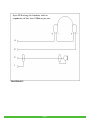
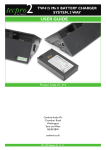
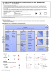
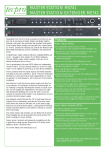
tecpro2
TECPRO BELTPACKS
by Canford
USER GUIDE
BP511
&
BP531
BP523
&
BP543
BP525
&
BP545
Product Code 27-511 BP511 Single Circuit beltpack (Male and Female XLR-3 Connectors, with loop through)
Product Code 27-523 BP523 Dual Circuit beltpack (Female XLR-3 Connectors, no loop through)
Product Code 27-525 BP525 Dual Circuit beltpack (Male and Female XLR-5 Connectors, with loop through)
Product Code 27-531 BP531 Single Circuit beltpack with vibration alert (Male and Female XLR-3 Connectors with loop through)
Product Code 27-543 BP543 Dual Circuit beltpack with vibration alert (Female XLR-3 Connectors, no loop through)
Product Code 27-545 BP545 Dual Circuit beltpack with vibration alert (Male and Female XLR-5 Connectors, with loop through)
Canford Audio Plc
Crowther Road
Washington
Tyne and Wear
NE38 0BW
www.canford.co.uk
02-454 (Issue 2) 10.09.
CONNECTING THE BELTPACK TO THE SYSTEM
BP511 and BP531
This single circuit beltpack is connected to the system via the available male and female XLR 3 pin
connectors. By convention the female connector is used as the input and the male connector as the output
enabling the cabling to be 'looped through' to the next station, if required.
BP523 and BP543
This dual circuit beltpack is connected to the system via two 3 pin, female, XLR type connectors.
They are marked Circuit I and Circuit II. There is no ‘loop through’ capability.
BP525 and BP545
This dual circuit beltpack is connected to the system via male and female, XLR 5 pin connectors.
By convention the female connector is used as the input and the male connector as the output, enabling the
wiring to be ‘looped through’ to the next station, if required.
BASIC OPERATION
Headset operation
A Tecpro compatible headset, wired as in diagram 1or 2 (as appropriate), should be plugged into the 4 pin
XLR connector on the rear of the station.
Located on the front panel, the “MIC” button activates the headset mic to speak to the system when
depressed. The thumb operated volume control can be adjusted for a comfortable listen level.
Side-tone adjustment
The level of user’s voice in the headset is called 'side-tone'. The required level can be set by adjusting the
recessed side-tone control on the front panel with a small screwdriver.
Signal light operation
The CALL pushbutton flashes a light in all outstations connected to the circuit. It is used to attract the
attention of a user that has the headset removed or volume level turned right down.
ClearCom Compatibility
Tecpro stations are completely compatible with Clear-Com stations. Any Tecpro stations added to Clearcom
will function as their Clear-Com equivalents. However, Clear-Com stations have a lower bridging impedance
and will degrade a Tecpro system slightly due to a reduction in side-tone stability incurred when a Clear-Com
outstation is used in a Tecpro communications system.
DETAILED OPERATION OF CONTROLS
The front panel houses the mic select and call buttons, headphone volume and side-tone adjust control(s).
Microphone Select
Press the “MIC” button briefly and it will illuminate green.This action switches on the mic circuitry and
allows the operation of other functions.
To switch off the mic circuitry press the “MIC” button briefly again.The lamp within the button will extinguish.
Holding the “MIC” button continuously keeps the mic circuitry alive for the duration of the press.
Call send
Ensure that a “MIC” circuit has been selected and that its associated lamp is illuminated.
Press the “CALL” button briefly.This will cause the lamps on all other beltpacks on the same circuit to flash
for approximately one second.The button will also illuminate red. A tone of similar duration will sound in
the headphones.
Remote Mic Kill send
Ensure mic circuits have been de-selected.
Depress the “CALL” button briefly three times. It will illuminate red for approximately two seconds.
During this time, briefly press the appropriate “MIC” button to switch off all mics on that circuit.
Page 1
PROGRAMMABLE OPTIONS
All settings revert to default when power is removed.
Default settings
1. Call alert tone ON/OFF - ON.
2. Bright or dim green LED’s - bright.
3. Vibration mode ON/OFF (Duplicates Call LED and will respond to a Call signal when the Call LED is
suppressed in ‘dim’ mode) - default is ON.
4. Disable or enable mic 1 (Mic 2) - ENABLED.
Preference Settings
Alert Tone
Switch off mic 1 and 2, hold down “Call” button for 3 seconds - red call LED flashes slowly for 2 secs.
To select alert tone off, while Call LED is flashing, press mic 1 - call alert tone on for 1 sec.
To select alert tone on, while Call LED is flashing, press mic 1 - call alert tone on for 1 sec.
When the call alert mode is programmed ON, 50mS of call alert tone acknowledges that the call switch is
pressed at the start of the 3 sec ‘hold down’.This button press acknowledgement is then suppressed until the
unit deselects set up mode and reverts to normal operation.
LED Brightness
Switch off mic 1 and 2, hold down “Call” button for 3 seconds - red call LED flashes slowly for 2 sec.
To select dim LEDS, while call LED is flashing, press mic 2 - call LEDs on dim for 1 sec.
To select bright LEDS, while call LED is flashing, press mic 2 - call LEDs on bright for 1 sec.
Vibration ON/OFF - BP531, BP543 and BP545 only
Switch off mic 1 and 2, hold down call for 3 sec - red call LED flashes slowly for 2 sec.
To select vibration off, while call LED is flashing, press mic 1 and mic 2 – unit vibrates for 1 sec.
To select vibration on, while call LED is flashing, press mic 1 and mic 2 - unit vibrates for 1 sec.
Mic Disable
Switch off mic 1 and 2, hold down call for 10 sec - red call LED flash rate changes to quick flash after 10 sec.
To disable Mic 1, while call LED is flashing, press mic 1 - Mic 1 LED flashes once.
To enable Mic 1, while call LED is flashing, press mic 1 - Mic 1 LED flashes 3 times.
To disable Mic 2, while call LED is flashing, press mic 2 - Mic 2 LED flashes once.
To enable Mic 2, while call LED is flashing, press mic 2 - Mic 2 LED flashes 3 times.
Page 2
MISCELLANEOUS
Circuit Enable/Disable
BP523 and BP543
If only one circuit is connected, then only this circuit is active. On the unused circuit, the line amplifier is disabled and the Mic LED does not light if the Mic key is pressed.
BP525 and BP545
With XLR-5 connectors, a given circuit is only active if its +24 volt line is powered.
Mic Disable
If no headset is connected, the Mic functions will be disabled.This will prevent immediate feedback if the
headset is re-connected with the volume control on maximum but the headset not being worn.
TECHNICAL SPECIFICATION
Power requirements:
Supply voltage:
Max current consumption:
With vibrate selected:
Headphone output:
Microphone input:
Connectors:
Case material:
Dimensions:
Weight without vibration motor:
Weight with vibration motor:
24 - 30 volts DC
40 mA in “Call” mode (all LEDs on)
50mA
8 ohm to 4Kohm headphones
200 to 600 ohm dynamic microphones
BP511 XLR 3 pin male and female - loop through
BP523 XLR 3 pin female, circuit I, circuit II
BP525 XLR 5 pin male and female - loop through
Headset - XLR 4 pin male
High impact ABS
120mm (L) x 103mm (W) x 54mm (H)
240g
260g
WIRING CONVENTIONS
System cable connectors:
XLR 3 pin
BP511
Pin 1 Earth/screen
Pin 2 +24V DC
Pin 3 Audio
XLR 5 pin
BP523
Pin 1
Pin 2
Pin 3
Pin 4
Pin 5
Headset connectors:
XLR 4 pin
Pin 1
Pin 2
Pin 3
Pin 4
and BP525
Earth/screen/0V
+24V DC
Audio, Circuit I
+24V DC
Audio Circuit II
Microphone Earth/screen
Microphone signal
Earphones Earth/screen
Earphones signal
Page 3
4-pin XLR wiring for headsets with an
impedance of more than 100ohms per ear.
4
3
2
1
DIAGRAM 1
Page 4
4-pin XLR wiring for headsets with an
impedance of less than 100ohms per ear.
4
3
2
1
DIAGRAM 2
Page 5
NOTES