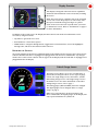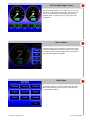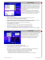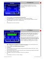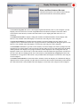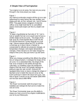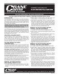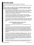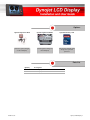
1
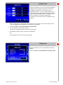
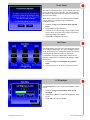
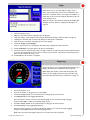
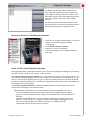
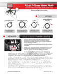
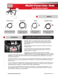
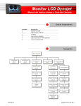
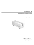
Options
Optional Expansion Hub
Optional Ignition Module
Optional Memory Card
View boost, speed, and gear
on the LCD Display.
View the ignition changes on
the LCD Display.
Log and store map data. Card
storage size is personal
preference.
Parts List
quantity
1
1
1
ILCD-100.02
description
LCD Display
LCD Display Cable
CD-ROM
Dynojet LCD Display - 1
Installation
USB cable
LD016
memory card
attach black
connector
door
The Dynojet LCD Display allows you to view real time
Power Commander data, log data being displayed, and
store and send maps to the Power Commander on the
fly. The Display provides the following information from
the Power Commander: throttle position, duty cycle,
current map, and fuel change. The Display can provide
more information by adding the Expansion Hub (boost,
speed, and gear) or the Ignition Module (ignition
change).
For assistance, please contact Dynojet Technical Support
at 1-800-992-4993, or email Dynojet at
[email protected].
1
Plug the black connector on the Display cable into the Display and the white connector into the
Power Commander expansion port.
Note: You may need to update the Power Commander firmware. Refer to page 12.
2
3
Open the door on the side of the Display.
Insert the memory card. The memory card is used to log and store map data. Refer to “Memory Card”
on page 2 and “Display File Manager” on page 10.
To connect the Display to your computer, plug a mini-B USB cable into the Display. Plug the USB
cable into your computer.
Note: Although the Display is water resistant, it is NOT waterproof. Remove the Display when
washing the motorcycle or riding in heavy rain. The Display will NOT be warranted if water damage is
present.
4
Memory Card
The Display supports memory cards from 128MB to 1
GB. The first time you install a memory card, you may
need to format it for the Display.
Note: Formatting the memory card will erase all data on
the memory card. If you use a memory card from your
digital camera, for example, any photos on that card will
be erased when formatting.
1
2
Insert the memory card into the slot located next to the USB port on the Display. Refer to
“Installation” on page 2.
Supply power to the Display by connecting a USB cable from the Display to your computer.
The SD Format screen will appear. If the SD Format screen does not appear, the memory card
has already been formatted and is ready to be used with the Display.
3
Touch Format to format the memory card or touch Cancel to abort the formatting process and exit
the screen.
If the memory card is not formatted, it will not be usable with the Display.
Once formatting is complete, the Format Confirmation screen will appear.
4
Touch OK in the Format Confirmation screen.
The memory card is now ready to store maps and data logging files.
www.powercommander.com
Dynojet LCD Display - 2
Display Overview
The Display is designed with touch screen capabilities.
All menus and information can be accessed by touching
the screen.
Note: The touch screen is delicate and can be scratched
or torn. Do not use sharp objects or unnecessary force.
Dynojet recommends using your finger or a plastic
stylus. If the screen does not respond where you touch
it, calibrate the screen. Refer to “Touch Panel” on page 8
for more information.
In addition to the touch screen, the Display has three buttons. All menus and information can be
accessed by using the buttons.
• Top button—goes back one screen.
• Bottom button—enters menu option.
• Middle button—navigates through menus, toggles between menu buttons, moves the highlighter
through a list, and moves the slider bar when selected.
UPDATING THE SETTINGS
Any setting changes for the Power Commander made in the Display will not appear in the Control Center
software until the USB cable is unplugged and plugged back into the Power Commander. Any changes
made in the Control Center software will not appear in the Display until the USB cable is unplugged and
plugged back into the Display.
Default Gauge Screen
The Gauge screen allows you to view real time data or
play back a saved log file. There are two types of gauge
screens, the single Gauge screen, shown here, and the
Dual Analog Gauges screen. The single Gauge screen is
the default screen. For more information on the Dual
Analog Gauges screen, refer to page 4.
The analog gauges (RPM and MPH) cannot be changed.
The digital gauges can be changed. Refer to “Gauge
Setup” on page 5.
Note: If you currently have an advanced map in the
Power Commander, the digital gauges on the Display will
only report information for cylinder #1.
www.powercommander.com
Dynojet LCD Display - 3
Dual Analog Gauges Screen
The Dual Analog Gauges screen allows you to view real
time data or play back a saved log file. This screen can
only be viewed when the Dual Analog Gauges box is
checked. Refer to “Gauge Setup” on page 5 for more
information.
Menu Choices
Touch the Gauge screen anywhere or press the bottom
button to bring up the list of menu choices. Each of the
four menu choices and their functions are described in
more detail throughout this guide.
Main Menu
The Display’s features can be accessed from the Main
Menu. The following sections contain a description of
each Main Menu feature.
www.powercommander.com
Dynojet LCD Display - 4
Log File Manage
Log File Management allows you to view, play back, and
delete log files. The naming is determined automatically
by the Display starting at DisplayLog00.displog through
DisplayLog99.displog. You must have a memory card to
view logged files.
Note: When the memory card is full, the Display will
notify you. The Display will not log any new files until
you send your current logged files to your computer and
erase files from the memory card. Refer to page 10.
1
2
3
4
Insert the memory card.
Supply power to the Display by connecting the USB cable or turning on the vehicle.
Touch the Gauge screen !Main Menu !Log File Manage.
Select the log file from the list. Scroll through the list by touching the up or down arrows or use the
middle button. Detailed information about the log file is displayed in the box below.
Note: No log files will be displayed until you log a run. Refer to page 9.
5
Touch Play File to play the file back.
The Display automatically switches to the Gauge screen and plays back the file.
6
When playback is complete, a window will appear. Touch OK to exit playback.
Note: If you touch the Gauge screen during playback, playback will be stopped.
7
You may also touch Delete File to delete the selected file or Exit to exit the screen with no changes.
Gauge Setup
Gauge Setup allows you to change the gauges shown on
the Default Gauge and Dual Analog Gauges screens.
The available options in the gauge drop down lists are
determined by which modules you have plugged in.
Refer to the list of optional modules on page 1.
1
2
3
Touch the Gauge screen !Main Menu !Gauge Setup.
Touch the drop down arrow next to the gauge you wish to change.
Touch an option from the drop down list.
Note: Gauge 5 will not be available unless you enable Dual Analog Gauges by checking the box.
4
Using the slider bar, change the Tach Range, Tach Redline, and Speedo Range.
• Tach Range determines the maximum tach value or number on the gauge.
• Tach Redline determines the visual redline shown on the gauge.
• Speedo Range determines the maximum speedometer value or number on the gauge.
www.powercommander.com
Dynojet LCD Display - 5
PC Module Info
Power Commander Info allows you to view the
information available about the connected Power
Commander.
1
2
Touch the Gauge screen !Main Menu !PC Module Info.
Touch Ignition Info to view the current information about the Ignition Module.
Note: There will be no information available if you do not have the Ignition Module connected.
3
Touch Fuel Info to return to Power Commander Info.
OR
Touch OK to return to the Main Menu.
TP Calibrate
Throttle Position Calibration allows you to calibrate the
throttle position to the current bike. The green bar
shows from closed to open throttle position; the red
arrows show the current throttle position.
Note: If you have calibrated the throttle position in the
Control Center software, it is not necessary to calibrate it
in the Display. Since variances in sensors can change, this
option is available in the Display to give you a quick
means of calibrating the throttle position if necessary.
Note: Changes made in the Display will not appear in the Control Center software until the USB
cable is unplugged and plugged back in to the Power Commander.
1
2
3
4
5
Touch the Gauge screen !Main Menu !TP Calibrate.
Touch Reset.
Close the throttle to set the closed position. This is indicated by the number shown under "closed"
and where the green bar starts.
Open the throttle all the way to set the open position. This is indicated by the number shown under
"open" and where the green bar ends.
Touch OK to send the current information to the Power Commander.
OR
Touch Cancel to exit the screen with no changes.
www.powercommander.com
Dynojet LCD Display - 6
Cylinder Trims
Cylinder Trims allows you to tune the fuel by adding or
taking fuel away from the current map in the Power
Commander. Adjustments can be made to each
individual cylinder +/- 5%. Any changes made to the
Cylinder Trims in the Display will overwrite the settings
in the Power Commander software. The Display will
show the number of cylinders available (This
information is sent from the Power Commander to the
display).
Note: Changes made in the Display will not appear in the Control Center software until the USB
cable is unplugged and plugged back into the Power Commander.
1
2
Touch the Gauge screen !Main Menu !Cylinder Trims.
Use the slide bar to add or take away fuel.
The percent of change is shown to the left of the slide bar.
3
Touch OK to send the values to the Power Commander.
OR
Touch Cancel to exit the screen with no changes.
Display Info
Display Info allows you to view information about the
Display.
Touch the Gauge screen !Main Menu !Display Info.
www.powercommander.com
Dynojet LCD Display - 7
Touch Panel
Touch Panel Calibration allows you to calibrate the touch
screen should it become unusable. This is done before
the Display is shipped, but may need to be performed by
the user in the future.
Note: If the touch screen is not calibrated and unusable,
use the buttons to navigate to the Touch Panel
Calibration screen.
1
2
3
4
Touch the Gauge screen !Main Menu !Touch
Panel.
Touch Start to begin calibration.
Touch the center of each target as they appear on the
screen. There are a total of five targets with the last
target appearing in the middle.
Touch OK to complete calibration.
Fuel Trims
Fuel Trims allows you to increase or decrease the fuel for
three different RPM ranges: low, mid, and high as shown
in the Fuel Trims screen. Using Fuel Trims is the same as
touching the three buttons found on the Power
Commander. If you have adjusted the buttons on the
faceplate of the Power Commander, the changes will be
shown here.
1
2
Touch the Gauge screen !Main Menu !Fuel
Trims.
Touch the arrows to increase or decrease the fuel.
LCD Backlight
LCD Backlight allows you to control the brightness of the
screen.
1
2
3
www.powercommander.com
Touch the Gauge screen !Main Menu !LCD
Backlight.
Touch Less or More to change the brightness of the
screen.
Touch OK to accept the changes.
Dynojet LCD Display - 8
Maps
Maps allows you to view the different maps, select a
map, and send the map to the Power Commander. You
must have a memory card to store maps; the number of
maps that can be sent to the Display depends on the size
of the memory card.
Maps are stored to the memory card with the Display File
Manager software. Refer to “Display File Manager” on
page 10.
1
2
3
4
5
6
7
8
9
Insert the memory card.
Plug the USB cable from the computer into the Display.
Copy the map(s) to the memory card using the Display File Manager software. Refer to page 10.
Unplug the USB cable and reconnect the Display to the Power Commander.
Turn the vehicle on which will supply power to the Display.
Touch the Gauge screen !Maps.
Select a map from the list. Information about the map is displayed in the box below.
Touch Send Map to send the map to the Power Commander.
Select a location to send the map, Map 1 or Map 2. This screen will only appear if the Expansion Hub
is present and Num Maps is set to 2 in the Control Center software. The position of the map switch
does not affect where the map is sent.
10 Touch OK once the transfer is complete.
Begin Log
Begin Log allows you to begin logging information to the
Display. You must have a memory card to log a file.
Note: When the memory card is full, the Display will
notify you. The Display will not log any new files until
you erase files from the memory card. Refer to page 10.
1
2
3
4
Insert the memory card.
Turn on the vehicle to supply power to the Display.
Touch the Gauge screen or any of the buttons to bring up the menu choices.
Touch Begin Log to start logging information.
Once the log has started, you will see the default gauge screen and the message Logging
Started. Touch OK to return to the default gauge screen.
5
6
Touch the Gauge screen or any of the buttons to bring up the menu choices.
Touch Stop Log to stop logging information.
Once the log has stopped, you will see the default gauge screen and the message Logging
Stopped. Touch OK to return to the default gauge screen.
Note: Once you touch the Begin Log button, it becomes the Stop Log button.
www.powercommander.com
Dynojet LCD Display - 9
Display File Manager
The Display File Manager software allows you to
move maps and log files between the Display and
your computer. The main interface contains a set of
tabs, Maps and Logs. These tabs display the files that
exist on the memory card in the corresponding
directory.
The main interface has five buttons which are also
accessible from the Actions menu. The main interface
buttons and menu items are described below.
INSTALLING THE DISPLAY FILE MANAGER SOFTWARE
1
2
3
4
Insert the CD, included with the Display, in your CDROM drive. The launch program will run
automatically.
Click LCD File Manager Software.
Follow the on-screen instructions.
Connect the Display to your computer using the
USB cable.
USING THE DISPLAY FILE MANAGER SOFTWARE
Data logging files have a .displog file extension. This is raw data. The Display File Manager converts these
files into a format viewable in Excel with a .csv file extension.
Click Options !Log File Export Options to set up the time interval between data samples for the .csv
files created from data logging files. The default 1.0 will put one second between each line in the .csv file.
Choose a value from the drop down list or type any valid real number directly into the field. By default,
the software will automatically create .csv files for any logs pulled from the device. This can be disabled by
deselecting Auto Convert Log Files.
Click Actions !Update Firmware to update the Display firmware. Update Firmware will only be
enabled when the Display is in bootloader mode.
Note: Updating the firmware is not necessary unless Dynojet has prompted you to do so.
• To enter bootloader you must have the three buttons on the Display depressed during
power up. Once in bootloader mode, a blue screen with some basic device information is
displayed.
• Enter the desired firmware file (.djf). The software will prepare the Display for the new
firmware to send the file to it. A progress indicator will be displayed during this process.
After a successful reprogram the software will start the new Display firmware
automatically. Resume normal software operation.
www.powercommander.com
Dynojet LCD Display - 10
Display File Manager Continued
USING THE MAIN INTERFACE BUTTONS
A detailed description of the main interface buttons
(also found under the Action menu) follows.
Click Convert Log Files To .csv to select Display log files that already exist on your computer (not the
Display) and convert them to an Excel compatible format for advanced analysis. These files will be
created in the same directory and have the same name as your .displog files but with a new .csv
extension.
Click Show Device Info to display a dialog that outlines the build information for the Display. This
button is only available when the Display is connected to the USB port on the computer.
Click Get Selected Files to pull files from the memory card in the Display and save them on your
computer. Enter a destination for the files. A progress indicator will be displayed during this process. This
button is only available when the Display is connected to the USB port on the computer.
Click Send Files to Device to put files on the memory card in the Display. You will be prompted for the
appropriate type of files based on the current tab selected, Maps or Logs. Any files selected in the dialog
will be pushed to the Display and a progress indicator will be displayed. You can drag files from any
Explorer window on to the file lists on the main interface. Files that match the appropriate extension for
the active tab .djm and .displog will be sent to the memory card immediately. Dragging directories and
invalid files is not supported. This button is only available when the Display is connected to the USB port
on the computer.
Click Delete Selected Files to delete files off the memory card in the Display. No confirmation dialog is
displayed and no undo is possible. Any files that are selected in the list will be immediately removed from
the card. This button is only available when the Display is connected to the USB port of the computer.
www.powercommander.com
Dynojet LCD Display - 11
Updating the Power Commander Software and Firmware
UPDATING THE CONTROL CENTER SOFTWARE
For the Display to operate properly with the Power Commander, the Control Center software version
must be 3.1.7 or higher. To verify the software version, open the Control Center software and
click Help !About Power Commander 3 USB software. If the Control Center software version is lower
than 3.1.7, use the following instructions:
1
2
3
Insert the CD, included with the Display, in your CD-ROM drive. The launch program will run
automatically.
Click Power Commander Control Center Software Update.
Follow the on-screen instructions.
VERIFYING THE POWER COMMANDER FIRMWARE
For the Display to operate properly with the Power Commander, the firmware version must be 2.1.2 or
higher. You will need to verify the current firmware version and may need to update the firmware.
1
2
3
4
Open the Control Center software.
Connect the USB cable from your computer to the
Power Commander.
Supply power to the Power Commander by
connecting the 9V adapter with a fresh 9V battery to
the expansion port of the Power Commander. You
can also supply power to the Power Commander by
turning the vehicle on.
Click View !Power Commander Information.
The Power Commander is always listed as
Module 0. The firmware type will be "Harley" for
a Harley Davidson or "Fuel" for all other types.
Note: Verify the Ignition Module firmware version, if
connected, as you may need to update this firmware as
well. The Ignition Module is always listed as Module 1
and the firmware type will be "Ignition". Refer to
“Updating the Ignition Module Firmware” on page 14.
UPDATING THE POWER COMMANDER FIRMWARE—FUEL 1.0.0.20/HARLEY 2.1.1 OR LATER
1
2
3
4
5
6
7
8
Open the Control Center software.
Connect the USB cable from your computer to the Power Commander.
Connect the 9V adapter to the expansion port of the Power Commander.
Connect a fresh 9V battery to the adapter.
Click Power Commander Tools !Update Firmware. The Open dialog box will appear.
Click the drop down arrow and select your CD-ROM drive.
Double-click the fscommand folder.
Double-click the PCIII folder.
Note: For Harley Davidson, double-click the HarleyPC folder.
9 Double-click the fscommand folder.
10 Click the firmware.dfu file.
11 Click Open. Wait for the progress bar to finish. When the progress bar reads Programmed
Successfully, your firmware is updated. If you get "Error Programming Module", disconnect the 9V
adapter and reconnect to the Power Commander. This will retry loading the firmware.
12 Click OK.
www.powercommander.com
Dynojet LCD Display - 12
Updating the Power Commander Software and Firmware Continued
UPDATING THE POWER COMMANDER FIRMWARE—EARLIER THAN FUEL 1.0.0.20/HARLEY 2.1.1
You must have a programmer (P/N PCPROG) to complete the following steps. This programmer is
included in some Ignition Modules or the HDREV kit. If you do not have a programmer, the programmer
can be purchased and will allow you to update your PCIII USB and Ignition Module. If you do not want to
purchase a programmer and cannot find a Tuning Center to update your PCIII USB, the Power
Commander can be sent to Dynojet to be updated. Please call 800-992-4993 for instructions.
1
2
Insert the CD in your CD-ROM drive. The launch
program will run automatically.
Click Power Commander Firmware Update.
If you have a Harley Davidson, click Power
Commander for Harley Davidson Firmware
Update.
Power Commander
expansion port
3
4
5
6
programmer
Connect the USB cable to the computer and to the
programmer.
Connect the white male plug from the programmer
to the expansion port on the Power Commander.
Connect the 9 volt adapter to the female plug on the
programmer.
Connect a fresh 9 volt battery to the adapter.
If everything is hooked up correctly, the light on the
Power Commander will either not be lit or you will
have one light at the top and one at the bottom of the
scale. If the Power Commander Lights are not lit,
repeat steps 2-7.
battery
connector
USB cable
The Update Firmware button will now be active.
7
Click Update Firmware. Wait for the blue scroll bar.
If you get a "Communication Error 8001", repeat
steps 4-8.
8
Disconnect the USB cable from the programmer and
connect it to the USB port on the Power
Commander.
9 Click Update Settings.
10 Once the Power Commander is successfully
updated, disconnect the programmer.
www.powercommander.com
Dynojet LCD Display - 13
Updating the Ignition Module Firmware
If the Ignition Module firmware is earlier than 2.1.1, the firmware will need to be updated.
You must have a programmer (P/N PCPROG) to complete the following steps. This programmer is
included in some Ignition Modules or the HDREV kit. If you do not have a programmer, the programmer
can be purchased and will allow you to update your PCIII USB and Ignition Module. If you do not want to
purchase a programmer and cannot find a Tuning Center to update your PCIII USB, the Power
Commander can be sent to Dynojet to be updated. Please call 800-992-4993 for instructions.
Note: Do not follow these steps if you have a Harley Davidson. Harley Davidsons do not employ a
separate Ignition Module.
1
2
3
4
5
Ignition Module
female plug
programmer
6
battery
connector
7
Insert the CD in your CD-ROM drive. The launch
program will run automatically.
Click Ignition Firmware Update.
Disconnect the Ignition Module from the Power
Commander.
Connect the USB cable to the computer and to the
programmer.
Connect the white male plug from the programmer
to the white female plug on the Ignition Module.
Connect the 9 volt adapter to the female plug on the
programmer.
Connect a fresh 9 volt battery to the adapter.
The Update Firmware button will now be active.
USB cable
8
Click Update Firmware. Wait for the blue scroll bar.
If you get a communication error 0005, click OK and
the firmware will continue to load.
Wait for the blue scroll bar to finish.
9
Disconnect the programmer from the Ignition
Module.
10 Connect the Ignition Module to the Power
Commander.
www.powercommander.com
Dynojet LCD Display - 14