1
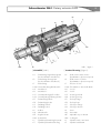
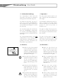
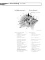
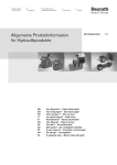
Schwenkmotor SM4
User Guide
Rotary actuator SM4
CHANCEN
für neue Techniken.
2
Betriebsanleitung · User Guide
Schwenkmotor PSM
[ Vorwort ]
[ Preface ]
Genaue Kenntnisse über das Produkt
und eine gewissenhafte Befolgung der
Betriebsanleitung gewähren einen störungsfreien Dauerbetrieb. Inbetriebnahme und Reparaturen dürfen nur
durch fachkundiges und geschultes Personal durchgeführt werden.
Possessing an exact knowledge of the
product and adhering conscientiously
to the User Guide will guarantee troublefree operation. Start up and repairs
should only be performed by experts
and trained staff.
Die Sicherheitsvorschriften der örtlichen
Institutionen sind zu beachten, z. B.
UVV, VDE, TÜV, etc.
Regional safety regulations should be
observed.
Die mit einem Schwenkmotor betriebenen Anlagen müssen so ausgelegt sein,
dass bei technischen oder menschlichen
Versagen keine Gefahr für Leib und
Leben besteht.
Maschinery driven by a rotary actuator
must be laid out in such a manner that
in case of technical or human failure
there is no danger of injury or fatal accident.
Die Betriebsanleitung ist vor dem Einbau
bzw. vor der Inbetriebnahme sorgfältig zu
lesen.
Please read the User Guide carefully before installation and start up.
Sollten sich trotzdem einmal Schwierigkeiten einstellen, so wenden Sie sich bitte
an unseren Kundendienst, der Ihnen gerne
behilflich sein wird.
Should you still encounter difficulties, contact our customer service department, who
will be happy to help.
Dieses Produkt ist nach dem heutigen
Stand der Technik gefertigt und zusammengebaut worden und ist betriebssicher.
Die Einzelteile und das fertige Produkt
werden durch unsere Qualitätssicherung
(DIN EN ISO 9001) laufend überwacht.
This product has been manufactured and
assembled in accordance with current
technical standards and is operationally
reliable. The individual parts and the end
product are checked continually by our
quality assurance department (DIN EN
ISO 9001).
Gegenüber Darstellungen und Angaben
dieser Betriebsanleitung sind technische
Änderungen, die zur Verbesserung dieses
Produktes notwendig werden, vorbehalten.
We reserve the right to make technical alterations to the designs and specifications
of this User Guide, which are necessary to
improve this product.
Schwenkmotor PSMSchwenkmotor SM4 · Rotary actuator SM4
3
[ Gewährleistung ]
[ Warranty ]
Die in diesem Dokument enthaltenen Informationen können ohne vorherige Ankündigung geändert werden.
The information in this document can be
altered without prior notice.
Eckart GmbH erteilt keine Gewährleistung
irgendwelcher Art hinsichtlich dieser Betriebsanleitung.
Eckart GmbH issues no guarantee of any
kind with regard to this User Guide.
Eckart GmbH lehnt insbesondere die stillschweigende Gewährleistung der Marktfähigkeit und Eignung für einen bestimmten
Zweck ab.
Eckart GmbH rejects the implied guarantee of marketability and aptitude for a certain purpose.
Eckart GmbH ist nicht für irgendwelche
direkten, indirekten, Neben-, Folge- oder
andere Schäden im Zusammenhang mit
der Bereitstellung oder Verwendung dieser Betriebsanleitung haftbar.
Eckart GmbH is not liable for any direct,
indirect, collateral, consequential or other
damage in connection lines with the provision or use of this User Guide.
[ Symbolerklärung ]
[ Explanation of symbols ]
Es bedeuten:
They mean:
Warnung, Gefahr
Hinweis
Warning, danger
Information
4
Betriebsanleitung · User Guide
Schwenkmotor PSM
Inhalt
1. Funktionsbeschreibung
Table of contents
6
1. Operation
6
2. Hinweise
6-7
2. Information
6-7
3. Vor dem Einbau
7-8
3. Before installation
7-8
4. Einbau
8-9
4. Installation
8-9
5. Inbetriebnahme
9 - 11
5. Start up
6. Nullstellung der Abtriebswelle 11
6. Drive shaft datum
7. Veränderung
der Nullstellung
7. Adjusting
the drive shaft datum
12 - 15
9 - 11
11
12 - 15
8. Drehrichtung
15
8. Direction of rotation
15
9. Betriebsdruck
15
9. Operating pressure
15
10. Drehwinkelspiel
16
10. Backlash
16
11. Drehwinkeleinstellung 16 - 17
11. Angle of rotation setting 16 - 17
12. Druckflüssigkeit
12. Hydraulic fluid
18
18
13. Druckflüssigkeitswechsel 18
13. Changing hydraulic fluids 18
14. Betriebstemperatur
18
14. Operating temperature
18
15. Filterung
19
15. Filtration
19
16. Leckage
19
16. Leakage
19
17. Endlage
19 - 20
17. End position
19 - 20
18. Drehmoment
20
18. Torque output
20
19. Rückstellkräfte
20
19. Resetting forces
20
20. Anschlussleitungen
21
20. Pressure supply lines
21
21. Sperrventile
21
21. Load valves
21
22. Wartung
21
22. Maintenance
21
23. Endlagendämpfung 22 - 25
23. End cushioning
22 - 25
24. Positionieren
25
24. Positioning
25
25. Lagerung
26
25. Storage
26
26. Gewicht
26
26. Weight
26
27. Ersatzteile,
Ersatzteilliste
26
27. Replacement parts,
list of replacement parts 26
Schwenkmotor PSMSchwenkmotor SM4 · Rotary actuator SM4
5
RE
Y
G2
B1
A1 G1
A
KM
F
S2
Z
E2
K
B
E1
S1
GW
Bild-1 / figure-1
W
[ Schnittbild ] (Bild-1)
[ Sectional drawing ] (figure-1)
•A
•A
- Drehrichtung Gegen-Uhrzeigersinn
(bei Druckeintritt in Anschluss A)
• B - Drehrichtung Uhrzeigersinn
(bei Druckeintritt in Anschluss B)
• F - Blickrichtung
• GW- Gewindebohrung Abtriebswelle
• A1 - Anschluss A1
• B1 - Anschluss B1
• G1 - Gewindepaarung Welle–Kolben
• G2 - Gewindepaarung Zahnring–Kolben
• E1 - Endanschlag Flansch
• E2 - Endanschlag Boden
• S1 - Entlüftung Flansch
• S2 - Entlüftung Boden
• K - Kolben
• W - Abtriebswelle
• RE - Reguliereinsatz
• KM - Kontermutter
• Y - Zylinderkopfschraube Reguliereinsatz
• Z - Zylinderkopfschraube Nullstellung
- Shaft rotation anti-clockwise
(by admittance of pressure in port A)
• B - Shaft rotation clockwise
(by admittance of pressure in port B)
• F - Direction of view
• GW- Threaded bore drive shaft datum
• A1 - Port A1
• B1 - Port B1
• G1 - Helical gear shaft
•G2 - Helical gear ring
•E1 - End stop flange
•E2 - End stop base
•S1 - Bleed port Flange
•S2 - Bleed port bottom
•K - Piston
•W - Drive-shaft
•RE - Adjustable stop on buttom
•KM - Locking nut
•Y - Cylinder head control insert
•Z - Cylinder head datum
6
Betriebsanleitung · User Guide
Schwenkmotor PSM
[ 1. Funktionsbeschreibung ]
[ 1. Operation ]
Der Schwenkmotor SM4 wird zum
Schwenken oder Drehen von Nutzlasten
mit begrenztem Drehwinkel eingesetzt.
The rotary actuator SM4 is used for rotating or turning useful loads with limited rotation angle.
Der Kolben K (siehe Bild 1 auf Seite 5)
wird, wie in einem Hydraulikzylinder,
durch hydraulische Kraft zwischen den
zwei mechanischen Endlagen E1 und E2
linear bewegt.
As in a hydraulic cylinder the piston K (see
figure-1 on page 5) is moved in a linear
motion between the two mechanical end
positions E1 and E2 by means of
hydraulic power.
Die Linearbewegung wird mechanisch,
durch die mehrgängigen Steilgewinde
G1 und G2 in eine Drehbewegung umgewandelt und auf die Abtriebswelle W
übertragen.
Through the multiple helical gears the
linear motion is mechanically transformed
into a turning motion and transferred to the
drive shaft W.
Die Steilgewindepaarungen sind nicht
selbsthemmend. Durch Zwangsschmierung und nitrierte Oberflächen der Steilgewinde ist eine hohe Lebensdauer des
Schwenkmotors gewährleistet.
The pairs of helical gears are not selfinhibiting. Positive lubrication and nitriding
of the surfaces of the helical gears ensures
a long service life of the rotary actuator.
[ 2. Hinweise ]
[ 2. Information ]
●
Stellen Sie sicher, dass niemand
in den Schwenkbereich der beweglichen Masse greifen kann,
und keine Fremdgegenstände
dorthin gelangen (z. B. mit selbstgefertigtem Schutzgitter).
●
Make sure that nobody can
place the hand in the swivel
range of the moveable mass,
and that no objects lie in the path
of the moveable mass (e.g. with
shopmade protective grill).
●
Verwenden Sie bei Zubehör nur
zugelassene Bauteile. Beachten
Sie die Vorschriften der Hersteller für z.B. Verschraubungen,
Rohre, Schlauchleitungen, Ventile, etc.
●
Only use permitted parts when
adding fittings. Observe the
manufacture’s guidelines for
example for threaded joints,
tubing, flexible sheathed cables
and valves, etc.
●
Sichern Sie den Schwenkmotor
gegen hydraulische und mechanische Überlastung, z. B. durch
Sicherheitsventile, ext. Anschläge, etc..
●
Protect the rotary actuator
against hydraulic and mechanical overloading, by using for
example safety valves, ext. end
stops etc.
●
Vorsicht bei Betrieb mit Speicheranlagen! Speicheranlagen können auch bei abgeschalteter
Pumpe noch unter Druck stehen.
●
Caution during operation with
accumulators. Accumulators can
still be under pressure even when
pumps are turned off.
Schwenkmotor PSMSchwenkmotor SM4 · Rotary actuator SM4
[ 2. Hinweise ]
[ 2. Information ]
●
Bei Verwendung von Sperrventilen kann auch nach drucklosgeschalteter Versorgungsanlage der Schwenkmotor noch
unter Druck stehen.
●
When using load valves even
after the supply system pressure
has been switched off the rotary
actuator may still be under pressure.
●
Es ist empfehlenswert an Stelle
der Entlüftungsschrauben S1–S2
G1/8“ Entlüftungsventile oder
Messanschlüsse einzusetzen,
womit immer eine problemlose
Entlüftung und hydraulischer Entspannung vorgenommen werden kann.
●
We recommend replacing the
bleed screws S1 – S2 G1/8“
with bleed valves or measuring
connectors, whereby a troublefree bleeding and hydraulic
release can be undertaken.
[ 3. Vor dem Einbau ]
[ 3. Before installation ]
●
Untersuchen Sie den Schwenkmotor vor dem Einbau auf evtl.
Transportschäden oder sonstige
Beschädigungen. Garantieforderungen durch Beschädigungen können nach Einbau oder
Inbetriebnahme nicht akzeptiert
werden.
●
Examine the rotary actuator before installation for possible
damage during transportation or
other damage. Claims for damages under the guarantee cannot
be accepted after installation or
start up.
●
Überprüfen Sie ob die Technischen Daten des Schwenkmotors mit den Anforderungen
übereinstimmen.
●
Check that the technical data for
the rotary actuator complies with
requirements.
●
Überprüfen Sie vor dem Einbau
die Nullstellung der Abtriebswelle (siehe Kapitel 6/7). Diese
kann in beliebiger Position stehen.
●
Check the datum of the drive
shaft (see section 6/7). It can be
in any position.
●
Bringen Sie die Nullstellung der
Abtriebswelle in die für den
Einbau notwendige Position.
Dies geschieht entweder durch
mechanisches Drehen der Abtriebswelle W oder durch eine
hydraulische Betätigung des
Schwenkmotors.
●
Move the drive shaft into the
position required for installation.
This happens either by turning
the drive shaft mechanically or
through hydraulic operation of
the rotary actuator.
7
Betriebsanleitung · User Guide
8
[ 3. Vor dem Einbau ]
B1
[ 3. Before installation ]
●
Bei Druckbeaufschlagung in
Anschluss B1 dreht sich die
Abtriebswelle in Richtung B
(Uhrzeigersinn) und der Kolben
K bewegt sich in Richtung E1 bis
zur internen mechanischen Endlage. Diese Endlage ist die
Grundstellung und nicht verstellbar.
●
When pressure is applied in port
B1 the drive shaft turns in direction B (clockwise) and the piston
K moves in direction E1 up to the
internal mechanical end position.
This end position is the positve
stop and is not adjustable.
●
Bei Druckbeaufschlagung in
Anschluss A1 dreht sich die
Abtriebswelle in Richtung A
(gegen Uhrzeigersinn) und der
Kolben K bewegt sich in
Richtung E2 bis zur internen
mechanischen Endlage. Diese
Endlage ist verstellbar (siehe
Kapitel 11).
●
When pressure is applied in port
A1 the drive shaft turns in direction A (anti-clockwise) and the
piston K turns in the direction E2
to the internal mechanical end
position. This end position is
adjustable (see section 11).
B
A1
Schwenkmotor PSM
A
[ 4. Einbau ]
[ 4. Installation ]
●
Farbe oder sonstige anhaftenden Fremdteile müssen von der
Flanschauflage entfernt werden.
●
Paint or other parts stuck to the
flange must be removed.
●
Es ist darauf zu achten, dass die
Abtriebswelle W mit der Nabe,
sowie die Flanschflächen genau
fluchten, da sonst die maximal
zulässigen Radial- und Axialkräfte überschritten werden können.
●
Care should be taken to align
the drive shaft W perfectly with
the hub and the flange surfaces,
to avoid exceeding the maximum permitted radial and axial
forces.
●
Zur Montage der Abtriebswelle
W mit der Nabe ist die erforderliche Axialkraft durch Schub
über das Wellenende der
durchgehenden Abtriebswelle
W oder durch Zug mittels Gewindestange am Gewinde GW
vorzunehmen. Eine andere Montageweise kann bei Schwergängigkeit zur Überschreitung
der Axialkraft und damit zum
Lagerschaden führen.
●
The required axial force for mounting the drive shaft on the hub
can be generated by pushing on
the end of the continuous drive
shaft W or by pulling using the
threaded rod on the thread GW.
Mounting using a different method can mean exceeding the
axial force if there is tightness
and this can lead to bearing damage.
Schwenkmotor PSMSchwenkmotor SM4 · Rotary actuator SM4
[ 4. Einbau ]
[ 4. Installation ]
●
Bei der Zusatzeinrichtung Endlagendämpfung Z1 muss bei
einigen Baugrößen vor Befestigung des Schwenkmotors die
Drosselschraube DS mit der
Dichtmutter DM an der Flanschseite entfernt werden (siehe
Seite 22). Nach der Befestigung
des Schwenkmotors sind diese
wieder einzusetzen (siehe Kapitel 24).
●
When the end cushioning option
Z1 is used and before the installation of the rotary actuator,
remove the flow control screw
DS and seal lucking nut DM (see
page 22). You will now have
access to the front mounting
bold. After the rotary actuator
has been mounted the cushion
assembly put back in place (see
section 24).
●
Weiterhin ist darauf zu achten,
dass die Anschlussleitungen bis
zum Wegeventil so kurz wie
möglich gehalten werden, um
einen Druckflüssigkeitsaustausch
zu garantieren.
●
Additional care should be taken
that the supply lines to the directional valve are kept as short as
possible to guarantee an exchange of hydraulic fluid.
●
Vor Anschluss der Rohrleitungen
ist das Rohrsystem gründlich zu
reinigen. Warm behandelte
Rohre sind evtl. zu beizen.
●
Before connecting the piping the
pipe system should be cleaned
thoroughly. Heat-treated pipes
should be scoured.
●
Bei eventuellem Ersatzteilwechsel ist in jeden Fall der Schwenkmotor auszubauen. Hierzu ist
der erforderlichen Freiraum zu
berücksichtigen, um einen Ersatzteilwechsel problemlos durchführen zu können.
●
When changing the replacement parts the rotary actuator
needs to be dismantled. It is
therefore necessary to allow
enough clearance for this to be
carried out without any problem.
[ 5. Inbetriebnahme ]
[ 5. Start up ]
●
Bei der Inbetriebnahme muss
sehr sorgfältig vorgegangen
werden. Bei unsachgemäßer
Handhabung kann der Schwenkmotor beschädigt oder zerstört
werden.
●
Care must be taken during the
start up. If handled improperly
the rotary actuator could be
damaged or ruined.
●
Vor der ersten Bewegung sind
beide Druckkammern des
Schwenkmotors mit der Druckflüssigkeit zu füllen! Das Befüllen,
sowie die ersten Bewegungen
sollten, wenn möglich, ohne Last
geschehen.
●
Before the first movement, the rotary actuato‘s pressure chambers must be filled with hydraulic
fluid. Filling of the chambers and
the first movement should ideally
take place without a load.
9
10
Betriebsanleitung · User Guide
[ 5. Inbetriebnahme ]
Schwenkmotor PSM
[ 5. Start up ]
Ist dies aus technischen Gründen
nicht möglich, muss bei der Befüllung und der Erstbetätigung, besonders sorgfältig vorgegangen
werden.
If this is not be possible for technical reasons, extra special care
must be taken when filling the
chambers and during the first
operation.
●
Betriebsdruck und Flussmenge
müssen auf ein Minimum reduziert werden.
●
The operating pressure and
flows should be reduced to a
minimum if possible.
●
Bei Vorhandensein von einstellbaren Drosselventilen sind diese
zu schließen und nach und nach
bei wechselseitiger Druckbeaufschlagung langsam zu öffnen.
Parallel dazu sollten beide
Druckkammern durch wechselseitiges Öffnen der Entlüftungsschrauben S1– S2 entlüftet werden.
●
When the cushion option ist used
the flow control screw should be
closed and opened slowly allowing pressure in both directions.
At the same time, bleed the
actuator by opening the bleed
screws S1 then S2.
●
Um einen bequemen und sauberen Entlüftungsvorgang durchführen zu können, sind an Stelle
der Entlüftungsschrauben S1 –
S2 G1/8“ Entlüftungsventile
oder Messverschraubungen zu
empfehlen.
●
To ensure that bleeding is easy
and clean it is recommended
that bleed valves or test fittings
are used instead of bleed screws
S1 and S2.
●
Ein nicht mit Druckflüssigkeit befüllter Schwenkmotor kann bei
Erstbetätigung, je nach Einsatzfall, bereits beschädigt oder zerstört werden.
●
A rotary actuator not filled with
hydraulic fluid can be damaged
or destroyed during its first operation depending on the individual case.
●
Nachdem sichergestellt ist,
dass beide Druckkammern des
Schwenkmotors gefüllt und entlüftet sind, kann vorsichtig mit
dem Betrieb begonnen werden.
Nach einigen Bewegungen des
Schwenkmotors kann mit max.
Betriebsdruck und Ölmenge gearbeitet werden.
●
Once it has been determined
that both pressure chambers
have been filled and bled, the
operation can be started with
caution. After a few movements
of the rotary actuator it can be
operated with maximum pressure
and maximum amount of oil.
Schwenkmotor PSMSchwenkmotor SM4 · Rotary actuator SM4
[ 5. Inbetriebnahme ]
[ 5. Start up ]
●
Sollten die zuvor beschriebenen
Vorgehensweisen aus technischen Gründen nicht möglich
sein, muss der Schwenkmotor
mittels Handpumpe oder Kleinaggregat über die Gewindebohrungen der Belüftungsschrauben S1 – S2 G1/8“
befüllt werden.
●
Bei Schwenkmotoren mit Endlagendämpfung Z1 ist vor dem
Betrieb mit max. Leistung die
Endlagendämpfung entsprechend abzustimmen (siehe Kapitel 24).
[ 6. Nullstellung der Abtriebswelle ]
Should the procedures described
above not be possible for technical
reasons, the rotary actuator must
be filled using a hand pump or
small unit via the threaded bores
of the bleed screws S1 – S2
G1/8”.
●
●
In the case of rotary actuators
with end cushioning Z1, the end
cushioning should be adjusted
before operation for maximum
power (see section 24).
[ 6. Drive Shaft Datum ]
Die Nullstellung der Abtriebswelle
erfolgt werksseitig wie im Bild-2
dargestellt, bei Kolben K in Endlage
E1.
The drive shaft datum is adjusted at
the factory as shown in figure-2,
with the piston K resting against the
end stop E1.
A1
=
11
K B1
=
g
°+
90 instellunfactor
anu
rkse
We d by m
us te
adj
A
1°
F
E1
E2
B
W
S1
S2
Z
Bild-2 / figure-2
Betriebsanleitung · User Guide
12
[ 7. Veränderung der Nullstellung ]
B1
Schwenkmotor PSM
[ 7. Adjusting the drive shaft datum ]
●
Die Nullstellung der Abtriebswelle kann individuell verstellt
werden. Die Einstellung sollte
möglichst vor der Montage der
Last vorgenommen werden.
●
Adjustment of the drive shaft datum can be carried out individually. If possible setting should be
carried out before the load is
placed.
●
Der Kolben K wird durch Druckbeaufschlagung an B1 oder
durch Drehen der Abtriebswelle
W in Drehrichtung B (Uhrzeigersinn) in die Endlage E1 gebracht.
●
The piston K is brought in the end
position E1 through oil pressure
at B1 or through turning the drive
shaft W in direction B (clockwise).
●
Bei Schwenkmotoren mit der Zusatzeinrichtung Endlagendämpfung Z1 (ohne Abbildung) ist
zu empfehlen durch Linksdrehen
der Drosselschraube DS die
Dämpfungswirkung zu neutralisieren, da sonst der Kolben K
durch die Dämpfungswirkung
aus der Endlage E1 verschoben
werden kann (siehe Bild-2).
Durch Öffnen der Entlüftungsschrauben S1 und S2 kann die
Dämpfungswirkung ebenfalls
neutralisiert werden.
●
In the case of rotary actuators
with the attachment end cushioning Z1 (not illustrated) the backpressure action should be neutralised by turning the flow
control screw DS to the left,
otherwise the piston can be pushed out of the stroke stop flange
by the backpressure action (see
figure-2). The backpressure action can also be neutralised by
opening the bleed screws S1
and S2.
●
Nun müssen beide Kammern
des Schwenkmotors drucklos
gemacht werden. Hierzu ist es
empfehlenswert anstelle der
Entlüftungsschrauben S1 – S2
Entlüftungsventile oder Messverschraubungen zu verwenden.
●
Both chambers of the rotary
actuator must now be depressurised. It is recommended that
bleed valves or test fittings be
used instead of bleed screws S1
and S2.
●
ACHTUNG: Es darf keine Last
von außen auf die Abtriebswelle
W einwirken, da die Last nach
dem Lösen der Zylinderkopfschrauben Z in eine unkontrollierte und gefährliche Bewegung
geraten kann.
●
CAUTION: There must be no
external load on the drive shaft
W as once the cylinder cap
screws Z have been loosened
the load could move about in an
uncontrolled and dangerous
way.
B
Schwenkmotor PSMSchwenkmotor SM4 · Rotary actuator SM4
[ 7. Veränderung der Nullstellung ]
B
[ 7. Adjusting the drive shaft datum ]
●
Zur Veränderung der Nullstellung werden die Zylinderkopfschrauben Z nur soweit gelöst,
dass keine Berührung der
Schraubenkopfflächen mit den
Anschraubflächen mehr besteht.
●
To adjust the drive shaft, loosen
the cylinder cap screws Z to
where the bolt head is no longer
in contact between the bottom
flange and the haeds of the cylinder cap screws.
●
Bevor die Zylinderkopfschrauben Z gelöst werden und der
Schwenkmotor drucklos gemacht wird, ist es empfehlenswert die Drehwinkelposition mit
einem geeigneten Messmittel
(z. B. ein Hebel am Wellenende
und Messuhr) zu überwachen
um etwaige Drehwinkelveränderungen beim Lösen der Schrauben zu erkennen und mit dem
Verstellvorgang kompensieren
zu können.
●
Before the cylinder cap screws Z
are loosened and the rotary
actuator is depressurised, we recommend monitoring the angle
of rotation with a suitable measuring device (e.g. a lever at the
shaft pivot and a dial gauge) to
detect any possible changes in
the angle of rotation and to compensate by making the appropriate adjustment.
●
Durch Drehen der Abtriebswelle
W in Drehrichtung B (Uhrzeigersinn) wird die gewünschte Passfederstellung erreicht.
●
By turning the drive shaft W in direction B (clockwise) the desired
key setting can be made.
●
Beim Überschreiten der gewünschten Nullstellung sollte die
Abtriebswelle W nicht in Drehrichtung A (gegen Uhrzeigersinn) zurückgedreht werden,
sondern um 360 weiter in
Drehrichtung B bis zum erneuten
Erreichen der gewünschten
Passfederstellung gedreht werden. Eine Korrektur durch entgegengesetztes Verdrehen der
Abtriebswelle W in Drehrichtung
A ist nicht empfehlenswert.
●
Should the desired position be
passed, the drive shaft W should
not be turned back in direction A
(anti-clockwise), but should be
turned 360 forwards in direction B until the desired key setting
is reached again. Correction by
turning the drive shaft W in direction A is not recommended.
●
Sollte eine Verstellung der Passfederlage durch Drehen der
Abtriebswelle W in Richtung A
nötig sein, bitten wir um Rücksprache im Werk.
●
If adjusting the keys by turning
the drive shaft W in direction A is
only option, please contact the
manufactory.
A
13
14
Betriebsanleitung · User Guide
[ 7. Veränderung der Nullstellung ]
Schwenkmotor PSM
[ 7. Adjusting the drive shaft datum ]
ACHTUNG: Bei Schwenkmotoren mit der Zusatzeinrichtung
Endlagendämpfung Z1 ist zu
berücksichtigen, dass beim
Verstellen der Nullstellung die
Schlitze und Fixierbohrungen
der Dämpfungsringe DR in den
Bereich der Dämpfungsbohrungen D gelangen können, wodurch die Endlagendämpfung
wirkungslos wird (siehe Kapitel
24).
Sollte bei Schwenkmotoren mit
Endlagendämpfung Z1 eine
Verstellung von mehr als 10 notwendig werden ist eine Rücksprache mit dem Werk empfehlenswert.
●
●
Ist die vorgenommene Verstellung der Nullstellung in
Ordnung sind die Zylinderkopfschrauben Z über Kreuz mit
einem Voranziehmoment MV
und einem Endanziehmoment
ME anzuziehen. Die Anzugsmomente entnehmen Sie der Tabelle
Seite 15.
●
If the adjustment made is correct,
the cylinder cap screws Z should
be tightened alternately on the
left and right sides with a forward torque of MV and an end
torque of ME. The tightening torques can be found in the table
below.
●
ACHTUNG: Die vorgegebenen
Anziehmomente MV und ME
sind unbedingt zu beachten.
●
CAUTION: The given torques
Mv and ME must be observed
completely.
●
ACHTUNG: Vor dem Betrieb
mit Last und max. Geschwindigkeit ist die Drosselschraube
DS wieder einzudrehen und die
Dämpfungswirkung zu optimieren (siehe Kapitel 24), bzw. die
Entlüftungsschrauben S1 und S2
zu schließen.
●
CAUTION: Before operation
with load and maximum speed
the flow control screw DS should
be screwed in again and the
damping effect should be optimised (see section 24) and the
bleed screws S1 and S2 should
be closed.
●
CAUTION: Rotary actuators
with the attachment end cushioning Z1 it should be noted that
the slots and fixed holes of the
cushioning rings DR could move
to the area of the cushioning
holes D during the adjustment of
the datum. As a result the end
cushioning would become ineffective (see section 24).
Should an adjustment of more
than 10 be necessary for rotary
actuators with end cushioning
Z1, consultation with the factory
is recommended.
Schwenkmotor PSMSchwenkmotor SM4 · Rotary actuator SM4
[ 7. Veränderung der Nullstellung ]
Baugröße
(Kolben-Ø)
Size
(Piston-Ø)
[ 7. Adjusting the drive shaft datum ]
Voranziehmoment Endanziehmoment
MV [Nm]
ME [Nm]
Gewindegröße
Schlüsselweite
Tighting torque
MV [Nm]
Finish torque
ME [Nm]
Size
of thread
Wrench
size
5
11
11
22
22
38
105
105
105
186
186
335
670
14
34
34
67
67
115
315
315
315
560
560
1000
2000
M6
M8
M8
M10
M10
M12
M16
M16
M16
M20
M20
M24
M30
5
6
6
8
8
10
14
14
14
17
17
19
20
40
50
63
80
100
125
140
160
180
200
225
250
300
[ 8. Drehrichtung ]
A1
15
Bei Druckeintritt in Anschluss A1
und Blickrichtung F dreht sich die
Abtriebswelle W in Pfeilrichtung A
(gegen Uhrzeigersinn).
[ 8. Direction of rotation ]
When pressure is admitted in port
A1 and view direction F the drive
shaft turns in arrow direction A (anti-clockwise)
A
[ 9. Betriebsdruck ]
[ 9. Operating pressure ]
Der maximale Betriebsdruck des
Schwenkmotors beträgt 250 bar.
Durch reibungsarme Dichtungen ist
der Schwenkmotor bereits ab 10
bar Betriebsdruck funktionsfähig
und somit ab ca. 20 bar wirtschaftlich einsetzbar.
The maximum operating pressure
of the rotary actuator is 250 bar
(3,625 psi). The standard low friction seals allow the rotary actuator
to breakaway at 10 bar (145 psi).
The rotary actuator can be operate
at approximately 20 bars (290 psi).
Für besonders langsame Schwenkbewegungen können auch stickslip-freie Dichtungen als Sonderausführung geliefert werden.
For especially low breakaway
pressure a stick free seal can be
supplied as a special option for
actuators.
Betriebsanleitung · User Guide
16
[ 10. Drehwinkelspiel ]
Die Steilgewindepaare bzw. Umlenkgewinde benötigen für ihre
Funktionsfähigkeit ein gewisses
Spiel, das bei ca. 20 Winkelminuten in der Endlage liegt.
[ 11. Drehwinkeleinstellung ]
Schwenkmotor PSM
[ 10. Backlash ]
Mechanical backlash due the
manufactoring tolerances required
by the helical gears is approximately 20 angular minutes in the
end position.
[ 11. Setting angle of rotation ]
KM
RE
Y
Bild-3 / figure-3
KM
–
+
RE
Die serienmäßig eingebaute Drehwinkeleinstellung lässt, ausgehend
vom Standard-Drehwinkel, eine
Winkeleinstellung im Bereich von
± 5 zu. Eine Einstellung ist nur im
drucklosen Zustand des Schwenkmotors und an der Endlage E2
möglich.
The standard Eckart rotary actuator
has an end stop adjustment of ± 5.
This feature is standard on all SM4
models. This adjustment can only
be made if the rotary actuator is not
pressurized and at the end position
E2.
Zur Verstellung ist zuerst die Kontermutter KM mit einem Stirnlochschlüssel (DIN 3116) linksdrehend
zu lösen. Danach kann der
Reguliereinsatz RE mit dem gleichen Stirnlochschlüssel auf den gewünschten Drehwinkel eingestellt
werden. Rechtdrehend wird der
Schwenkwinkel kleiner, linksdrehend wird der Schwenkwinkel
größer. Nach eingestelltem Winkel
ist die Kontermutter KM rechtsdrehend wieder fest anziehen.
In order to adjust the angle, the
locking nut KM must first be loosened by turning a spanner wrench
(DIN 3116) to the left. After this
the adjusting insert RE can be set to
desired angle using the same spanner wrench. By turning it to the right
the angle of rotation becomes
smaller and by turning it to the left
the angle becomes greater. After
the angle has been set the locking
nut KM must be re-tightened by
being turned to the right.
Schwenkmotor PSMSchwenkmotor SM4 · Rotary actuator SM4
[ 11. Drehwinkeleinstellung ]
[ 11. Setting angle of rotation ]
ACHTUNG: Die Schrauben Y dürfen nicht gelöst werden.
CAUTION: The cylinder cap
screws Y must not be loosened.
Ist der Kolben in der Endlage E2
gegen den Reguliereinsatz RE angefahren, dann ist eine Verstellung
nur schwer oder gar nicht möglich.
Der Kolben K muss deshalb ein
Stück in Richtung E1 verschoben
werden (Drehung der Abtriebswelle W in Richtung B). Sollte
durch äußere Krafteinwirkung die
Abtriebswelle W in Drehrichtung A
gedreht und somit der Kolben K
wieder gegen den Reguliereinsatz
RE gefahren werden, ist dies durch
geeignete Maßnahmen zu verhindern.
If the piston is resting against the
adjustable stop on buttom RE (E2
position) it will make it difficult or
impossible to adjust. The piston K
must therefore be pushed slightly
in direction E1 (the drive shaft W in
direction B). Should the drive shaft
W be turned by an external force
in direction A then the piston K
moves again against the adjustable stop on buttum RE, this should
be prevented using appropriate
measures.
Bei Schwenkmotoren mit der
Zusatzeinrichtung Z1 – Endlagendämpfung ist zu berücksichtigen,
dass bei Verwendung der
Drehwinkeleinstellung sich die
Wirkung der Endlagendämpfung
im Bereich der Endlage E2 mit verändert.
It should be noted that rotary
actuators with the attachment Z1 –
end cushioning, the use of the rotation angle setting changes the
effect of the end cushioning in the
end position area E2 also changes.
Die Zusatzeinrichtung Z4 – Drehwinkelverstellung wird ebenso
gehandhabt wie die oben beschriebene serienmäßige Drehwinkeleinstellung. Bei der Zusatzeinrichtung Z4 kann der
Schwenkwinkel sowohl über seinen gesamten Schwenkbereich,
oder über einen Teilbereich nach
Kundenwunsch verstellt werden.
Bei der Verwendung der Zusatzeinrichtung Z4 ist eine Endlagendämpfung im Bereich der Endlage
E2 nur bei Erreichen des max.
Schwenkwinkels wirksam.
The Z4 option – angle of rotation
setting is handled in the same manor as the standard angle of rotation
described above. With the Z4 option the angle of rotation can be
adjusted over the entire range or
simply over a part of it. As noted
above the actuator with the option
end cushioning Z1 will only have a
damping effect with full travel of the
piston in the E2 area.
17
18
Betriebsanleitung · User Guide
[ 12. Druckflüssigkeit ]
Zu empfehlen sind Druckflüssigkeiten auf Mineralölbasis der
Gruppe HLP nach DIN 51524/
Teil 2 und VDMA-Blatt 24318.
Druckflüssigkeiten ohne Legierungselemente vermindern die
Lebensdauer des Schwenkmotors.
Bei Verwendung von schwer entflammbaren Druckflüssigkeiten bitten wir um Rückfrage.
Der Viskositätsbereich sollte zwischen 16 cSt und 68 cSt bei 40
bis 60 C liegen.
[ 13. Druckflüssigkeitswechsel ]
Schwenkmotor PSM
[ 12. Hydraulic fluids ]
We recommend mineral oil based
hydraulic fluids of the group HLP
as per DIN 51524/part 2 and
VDMA, recommendation 24318.
Fluids without emulsifying agents
will reduce the service life of the rotary actuator. For highly flammable
fluids, please consult the manufactor.
The recommended viscosity range
is 16cST and 68 cST at 40C to
60C (104F to 140F).
[ 13. Changing the hydraulic fluids ]
Der Druckflüssigkeitswechsel richtet sich nach der Größe der bestehenden Anlage und ist in regelmäßigen Abständen durchzuführen.
Changing the hydraulic fluids depends on the size of the existing
system and should be carried out
at regular intervals.
Ist das Druckflüssigkeitsvolumen
der Anschlussleitungen größer als
das Schluckvolumen pro Hub des
Schwenkmotors, ist keine Frischdruckflüssigkeitszufuhr mehr gewährleistet. Bei einem Druckflüssigkeitswechsel ist dann in jedem
Falle eine Spülung des Schwenkmotors mit neuer Druckflüssigkeit
vorzunehmen.
If the hydraulic fluid volume of the
supply lines is greater than the
absorption volume of the stroke of
the rotary actuator, a fresh supply
of hydraulic fluid is no longer
guaranteed. Each time the hydraulic fluid is changed the rotary actuator must be flush cleaned with
new hydraulic fluid.
[ 14. Betriebstemperatur ]
Die Betriebstemperatur kann unter
Beachtung der richtigen Viskosität
zwischen -25 C und +70 C liegen. Bei höherer thermischer
Belastung bitten wir um Rückfrage.
[ 14. Operating temperature ]
The operating temperature can range from -25C to +70C (-13F to
158F), providing suitable fluids
with the correct viscosity are used.
Please contact us for any applications outside these limits.
Schwenkmotor PSMSchwenkmotor SM4 · Rotary actuator SM4
[ 15. Filterung ]
Es ist darauf zu achten, dass die in
den Schwenkmotor gelangende
Druckflüssigkeit die Verschmutzungsklasse 19/15 nach ISO
4406 nicht überschreitet. In dem
Druckflüssigkeitskreislauf sollte deshalb eine Filterfeinheit von < 25 µm
installiert sein. Bei hermetisch geschlossenen Behältern ist ein
Rücklauffilter ausreichend. Bei offenen Behältern muss eine Druckfiltereinheit in die Druckleitung
installiert werden. Die vorgeschriebenen Wartungsabstände sind
gemäß Herstellerangaben einzuhalten.
[ 16. Leckage ]
Der Schwenkmotor ist auf Grund
seiner kreisrunden Dichtungen mit
gut abgedichteten Linearzylindern
zu vergleichen. Deshalb ist es auch
möglich, unter Last jede Zwischenstellung zu halten.
[ 17. Endlage ]
[ 15. Filtration ]
Care should be taken to ensure that
the hydraulic fluid used in the rotary
actuator does not exceed the contamination classification 19/15 in
accordance with ISO 4406.
Therefore a filter setting of < 25µm
or better should be installed in the
pressure line. With hermetically
sealed containers a return filter
should suffice. With open containers a pressure filter must be installed in the compressed air line. The
maintenance intervals described
above should be adhered to in line
with manufacturer specifications.
[ 16. Leakage ]
The rotary actuator can be compared with well sealed linear
cylinders because of its solid seals,
therefore allowing the load to be
held in any intermediate position.
[ 17. End position ]
Der Kolben K kann unter Last bis an
die Endanschläge E1 und E2 gefahren und belastet werden. Die
Endanschläge sind jedoch nur zur
Aufnahme des maximalen Drehmomentes bzw. des maximal zulässigen Betriebsdruckes ausgelegt.
The piston K can be moved under
load against the end stops E1 and
E2 and be held in this position. The
end stops are designed to withstand the force created by the
maximum allowable operating
pressure relating to the maximum
premissable torque output.
Werden die Innenanschläge als
Schwenkwinkelbegrenzung benutzt, dürfen die auf die Anschläge
wirkenden Kräfte (einschließlich
der entstehenden Massenkräfte)
nicht größer sein als die Kräfte, die
sich durch den maximal zul.
Betriebsdruck (250 bar) ergeben
würden.
If the internal stops are used to limit
the angle of rotation, the forces acting on the stops (including forces
due to inertia) must not be greater
than the forces, produced by the
maximum permitted operating pressure (250 bar/3,625 psi).
19
20
Betriebsanleitung · User Guide
[ 17. Endlage ]
Werden höhere Massenkräfte
erwartet, als die Innenanschläge
des Schwenkmotors aufnehmen
können, so empfehlen wir Endbegrenzungen außerhalb des
Schwenkmotors bzw. steuerungstechnische Lösungen.
[ 18. Drehmoment ]
Die angegebenen Drehmomente
sind Effektivmomente. Die DruckDrehmomentenkurve verläuft fast
linear. Das Drehmoment ist in beiden Drehrichtungen gleich. Bei
mehrschichtigem Betrieb, hoher
Beanspruchung oder kurzen
Taktzeiten empfehlen wir, einen
Sicherheitsfaktor von 1,2 bis 1,5 zu
berücksichtigen.
[ 19. Rückstellkräfte ]
Bei hermetischem Verschluss des
Schwenkmotors (z. B. durch hydraulisch entsperrbare Rückschlagventile) und Einwirkung einer
Rückstellkraft über die Abtriebswelle ensteht im Schwenkmotor ein
Haltedruck. Erreicht der Haltedruck
den Wert des Betriebsdruckes
wirkt ein ca. 38 % höheres Drehmoment auf die Abtriebswelle ein.
Werden Rückstellkräfte erwartet, ist
das bei der Größenauswahl des
Schwenkmotors zu beachten. Bei
Betrieb mit der Option Endlagendämpfung Z1 ist dies ebenso zu
berücksichtigen.
Schwenkmotor PSM
[ 17. End position ]
If higher forces can be expected,
we recommend installation of external stops or other methods of
control such as end cushioning or
control valves.
[ 18. Torque ]
The stated torque figures are effective torques, with the pressure versus the torque curve being virtually
linear. For mult-shift, heavy duty or
high frequency applications a safety factor between 1.2 and 1.5 is
recommended. Torque output is
equal in both directions.
[ 19. Resetting forces ]
With hermetic closing of the rotary
actuator (e.g. through hydraulic
unsealed non-return valves) and
exertion of a resetting force on the
drive shaft, holding pressure is
created in the rotary actuator. If the
holding pressure reaches the level
of the operating pressure then an
approximately 38 % higher torque
acts on the drive shaft. If resetting
forces are anticipated, this should
be considered when choosing the
size of your actuator. This should
also be considered when using the
end cushioning option Z1.
Schwenkmotor PSMSchwenkmotor SM4 · Rotary actuator SM4
[ 20. Anschlussleitungen ]
Um einen Druckflüssigkeitsaustausch zu garantieren, sollten die
Anschlussleitungen so kurz wie
möglich gehalten werden, bzw. ist
es empfehlenswert das Wegeventil
direkt auf den Schwenkmotor zu
montieren. Ist das nicht möglich,
empfehlen wir ein doppelt hydraulisch entsperrbares Wegeventil mit
zusätzlicher Tankleitung.
[ 21. Sperrventile ]
Bei hermetischem Verschluss des
Schwenkmotors (z. B. durch hydraulische Sperrventile) und einer
Wärmeeinwirkung von außen ist
zu beachten, dass pro 1 C Temperaturanstieg der hydraulische
Druck im Schwenkmotor um ca.
6 - 8 bar ansteigt. Bei starkem
Temperaturanstieg könnte der
erhöhte hydraulische Druck den
Schwenkmotor zerstören.
Sind Betriebsbedingungen mit starkem Temperaturanstieg zu erwarten, sind geeignete Schutzmaßnahmen (z. B. Sicherheitsventile
oder Schaltzyklen) vorzusehen.
[ 22. Wartung ]
Der Schwenkmotor ist im Prinzip
wartungsfrei. Es ist lediglich darauf
zu achten, dass ein Druckflüssigkeitswechsel in regelmäßigen Abständen eingehalten wird (siehe
Kapitel 13).
[ 20. Pressure supply lines ]
To guarantee an exchange of hydraulic fluids, the supply lines
should be kept as short as possible,
and it is recommended that the twoway valve be mounted directly on
the rotary actuator. Should this not
be possible, we recommend a
valve combination that will return
the hydraulic fluid back to tank on
each cycle.
[ 21. Load valves ]
With hermetic sealing of the rotary
actuator (e.g. using hydraulic load
valves) and an external thermal
effect, care should be taken to
ensure that the hydraulic pressure in
the rotary actuator increases by
approximately 6 - 8 bar (87 to 116
psi) per 1 C (33.8 F) temperature
increase. If the temperature rises
sharply, the increased hydraulic
pressure could destroy the rotary
actuator.
If operating conditions with a sharp
temperature increase are anticipated, appropriate safety measures
should be taken (e.g. sload holding / counter balance valves).
[ 22. Maintenance ]
In theory the rotary actuator does
not require maintenance. However,
care should be taken that the
hydraulic fluids are changed at
regular intervals (see section 13).
21
22
Betriebsanleitung · User Guide
Schwenkmotor PSM
[ 23. Endlagendämpfung Z1 ]
[ 23. End cushioning Z1 ]
R
A1
Q
Anschlussplatte - connection plate
D
DM
B1
R
K
DS
T
E1
DR
Bild-4 / figure-4
Funktionsbeschreibung (Bild-4)
Operation (figure-4)
Ausgangsposition
• Kolben K ist in Endstellung E2
• Anschluss A1 ist mit Druck
beaufschlagt
• Anschluss B1 ist drucklos
Starting position
• Piston K is in end position E2
• Port A1 is pressurised
Umschaltung in Schaltstellung 1
• Anschluss B1 wird mit Druck
beaufschlagt
• Kugelrückschlagventil R im
Anschluss B1 öffnet
• Druckflüssigkeit fließt frei in der
Zylinderraum ein
• Kolben K bewegt sich Richtung
Endlage E1 (Pfeilrichtung bei
Kolben K)
• Kugelrückschlagventil R im
Anschluss A1 ist geschlossen
• Druckflüssigkeit fließt frei durch
die Bohrungen D ab
Changing the direction of oil flow
• Port B1 is pressurised
• Port B1 is unpressurised
• Ball check valve R in port B1
opens
• Hydraulic fluid flows freely into
the cylinder space
• Piston K moves in direction
end position E1
(direction arrow piston K)
• Ball check valve R is closed in
port A1
• Pressure fluid flows off freely
through the holes D
Schwenkmotor PSMSchwenkmotor SM4 · Rotary actuator SM4
[ 23. Endlagendämpfung Z1 ]
[ 23. End cushioning Z1 ]
Dämpfungsvorgang
• Kolben K nähert sich der Endlage E1und verschließt nacheinander die Bohrungen D
• Kolbengeschwindigkeit wird fast
progressiv abgebremst
• Kolben K überdeckt nun völlig
die Bohrungen D
• Die Druckflüssigkeit kann nur
noch durch die Bohrung Q mit
der Drosselschraube DS zum
Anschluss A1 entweichen
• Der Dämpfungsendweg kann
mit der Drosselschraube DS beeinflusst werden; Diese Dämpfungsphase verläuft linear
Cushioning process
• Piston K now approaches the
end position E1 and seals the
holes D one after the other
• Piston speed is progressively
reduced
• Piston K now completely
covers holes D
• The pressure medium can now
only escape through the hole Q
with the adjusting screw DS to
the port A1
• The cushioning effect can therefore be adjusted again by the
adjusting screw DS; This cushioning phase runs linear
Bei Schwenkmotoren mit Endlagendämpfung sind die Kolben
am Umfang mit einem Dämpfungsring DR versehen, um eine
optimale Überdeckungen der
Dämpfungsbohrungen D zu gewährleisten. Die Dämpfungsringe
sind geschlitzt und werden mittels
Bohrung und Fixierstift gegen
Verdrehung gesichert.
Rotary actuators with end cushioning have a special cushining ring
DR located on the piston. The cushioning ring is designed to cover
the multiple cushioning holes. The
cushioning ring is slit, and press fit
to piston with additional locking
pin.
Während der Dämpfungsphase
wird der Rückfluss der Druckflüssigkeit progressiv gedrosselt,
wodurch je nach Größe des auftretenden Massenmomentes der
hydraulische Druck an der gedämpften Kolbenseite ansteigt. Es
ist darauf zu achten, dass der zu
erwartende Dämpfungsdruck den
max. zulässigen Betriebsdruck
nicht übersteigt.
During the cushioning phase, backflow of the hydraulic fluid is progressively mettered out, which causes the hydraulic pressure to rise on
the cushioned side of the piston,
depending on the size of the momentum of inertia caused. Care
should be taken to ensure that the
anticipated cushioning pressure
does not exceed the permitted
operating pressure.
Während der Inbetriebnahme von
Schwenkmotoren mit Endlagendämpfung sind deshalb Druckmessungen, möglichst mit elektronischen
Druckaufnehmern, vorzunehmen.
Pressure measurements should be
taken using electronic pressure
gauges, during the cycling.
23
24
Betriebsanleitung · User Guide
[ 23. Endlagendämpfung Z1 ]
Schwenkmotor PSM
[ 23. End cushioning Z1 ]
Besonders bei Tandembetrieb sind
Messungen der Dämpfungsdrücke
zwingend notwendig. Wenn zwei
oder mehr Schwenkmotoren
kraftschlüssig oder formschlüssig
zusammenwirken, müssen die
Dämpfungsdrücke der einzelnen
Schwenkmotoren auf einen gleichen Wert abgeglichen werden.
It is important to check pressure
when two or more units with the
cushion option are operating. The
rotary actuator running simultaneously or non-simultaneously must
be balanced out to the same pressure valve.
Die Anschlüsse der Druckmessgeräte sind an den Gewinden der
Entlüftungsschrauben S1 und S2 G
1/8“ vorzunehmen.
The pressure gauges should be
connected to the threads of the
bleed screws S1 and S2 G 1/8”.
Bei Messungen an den Versorgungsleitungen werden die Dämpfungsdrücke nicht erfasst! Die
Dämpfungsbohrungen D sind mit
Gewinde versehen, in welche
Düsen eingeschraubt werden können. Durch den Einsatz von Düsen
kann die Dämpfungswirkung, sowie
der Dämpfungsdruck positiv beeinflusst werden. Hierzu halten Sie
bitte Rücksprache mit unserem
Werk. Durch besondere Anpassung der Dämpfungsringe sind
auch spezifische Anpassungen des
Dämpfungsweges möglich. Hierzu
halten Sie bitte ebenfalls Rücksprache mit unserem Werk.
In the case of measurements on the
supply lines, the cushioning pressure is not measure. The cushioning
holes D are equipped with threads
into which nozzles can be screwed. By using nozzles the cushioning effect and the cushioning
pressure can be positively influenced. For information on this please
consult the factory. Adjusting the
cushioning ring will alter the cushioning flow path. For more information on this please consult the
factory.
Bei Schwenkmotoren mit Endlagendämpfung Z1 steigt die
Temperatur während des Betriebs
prozentual mehr als bei Schwenkmotoren ohne Endlagendämpfung.
Ein Druckflüssigkeitsaustausch ist
deshalb unbedingt zu berücksichtigen (siehe Kapitel 13 und 20).
Rotary actuators with end cushioning Z1 then units without cushionig. This therethore important that
an exchange of hydraulic fluid
should be given.
(see sections 13 and 20)
Schwenkmotor PSMSchwenkmotor SM4 · Rotary actuator SM4
[ 23. Endlagendämpfung Z1 ]
25
[ 23. End cushioning Z1 ]
HINWEIS: Bei vollständig geschlossener Drosselschraube DS
kann es möglich sein, dass die
Endlage nicht erreicht wird.
INFORMATION: When the flow
control screw DS is fully closed it is
possible that the end position may
not be reached.
ACHTUNG: Die Drosselschraube
DS ist nicht gegen vollständiges
Herausdrehen gesichert. Bei Verstellung der Drosselschraube darf
diese nur soweit herausgedreht
werden, dass das Maß T nicht
überschritten wird (siehe Tabelle
unten und Bild-4 auf Seite 22).
CAUTION: The flow control screw
DS is not protected against being
unscrewed fully. When adjusting
the flow control screw, it should
only be unscrewed to the point
where the measurement T is not
exceeded (see table below and
figure-4 on page 22).
Baugröße
Size 40
T
Anschluss A [mm]
50
63
80
100 125 140 160 180 200 225 250 300
11
11
11
11
11
11
11
11
11
11
11
–
–
11
11
11
11
11
16
16
16
16
16
16
–
–
Port A [mm]
T
Anschluss B [mm]
Port B [mm]
Das Maß T kann bei einigen
Baugrößen im Bereich des Anschlusses A1 und B1 unterschiedlich sein.
[ 24. Positionieren ]
The measurement T can differ
with individual models in the
area of ports A1 and B1.
[ 24. Positioning ]
Mit dem Schwenkmotor können je
nach Art der Ansteuerung stufenlose Winkelpositionen angefahren
werden.
Depending on the type of valves
used with the rotary actuator the
degree of rotation can be maintained.
Wenn Positionen im lastneutralen
Zustand angefahren werden (z. B.
horizontale Drehtische) ist das mechanische Winkelspiel (siehe
Kapitel 10) sowie die Kompressibilität der Druckflüssigkeit zu
berücksichtigen.
If loads are driven in a neutral load
status (e.g. horizontal index table),
the compressibility of the hydraulic
fluid and the tolerance of the gears
(see section10) should be considered.
Die Volumenveränderung bei mineralischen Hydraulikölen beträgt ca.
0,5 – 0,7 % pro 100 bar.
The compressibility of mineralbased hydraulic fluids is approximately 0.5 - 0.7 % per 100 bar
(1450 psi).
26
Betriebsanleitung · User Guide
[ 25. Einlagerung ]
Schwenkmotor PSM
[ 25. Storage ]
Die Schwenkmotoren sind ab
Werk im Innenbereich nur mit einem
Ölfilm versehen. Ist eine längere
Lagerung des Schwenkmotors zu
erwarten, muss dieser mit einem
geeigneten Konservierungsmittel
befüllt bzw. behandelt werden.
The rotary actuators are only provided with an oil film from the factory. If a long period of storage is
anticipated the rotary actuator must
be filled and handled with the appropriate preservative.
Die Schwenkmotoren sind in
Räumen mit geringen Temperaturschwankungen zu lagern. Temperaturschocks vom kalt in warm sind
dringend zu vermeiden.
The rotary actuators should be
stored in premises with low temperature fluctuations. You should urgent avoid temperature shocks
from cold to warm.
[ 26. Gewicht ]
Berücksichtigen Sie das Gewicht
des SM4. Es kann bis zu 1100 kg
und mehr betragen.
[ 27. Ersatzteile,
Ersatzteilliste ]
Ersatzteilliste, sowie Demontage
und Montageanleitung können auf
Wunsch bei unserem Kundendienst
angefordert werden.
[ 26. Weight ]
The weight of the SM4 should be considered. It can take up to 1100 kg (2425 lbs).
[ 27. Replacement parts,
lists of replacement parts ]
Lists of replacement parts, dismantling and assembly instructions can
be obtained from our customer service department.
Schwenkmotor PSMSchwenkmotor SM4 · Rotary actuator SM4
27
Schwenkmotor PSM
© ECKART GmbH 2003
Zuständige Vertretung:
ECKART GmbH
Gewerbegebiet Wallroth
D-36381 Schlüchtern
Telefon +49 (0)6661 9628-0
Telefax +49 (0)6661 9628-50
E-Mail [email protected]
http:// www.eckart-gmbh.de
Production 02/2003. © Günther Werbeservice
Betriebsanleitung · User Guide
22
28