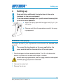
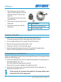
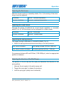
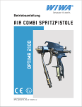
1
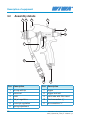
Operation manual OPTIMA 2100 Air Combi SPRAY GUN Translation of the original operation manual SPAC_Optima2100_1302_en • 0550012 • jw Inhaltsverzeichnis 1Preface..............................................................................................5 2Safety................................................................................................6 2.1 First read, then start...........................................................................6 2.3 Dangers caused by rebuilds and changes.........................................8 2.2 2.4 2.5 2.6 2.7 2.8 Description of symbols.......................................................................7 Dangers caused by attachments and spare parts.............................9 Dangers caused by emissions...........................................................9 Safety instructions...........................................................................10 Operating staff.................................................................................12 Safety measures at installation site.................................................13 2.9 Safety equipment.............................................................................13 3 Description of equipment..............................................................14 3.1 Intended use....................................................................................14 3.3 Technical data..................................................................................17 3.2 3.3.1 3.3.2 3.3.3 3.3.4 Assembly details..............................................................................16 Connected loads..............................................................................17 Material consumption and output values.........................................17 Air consumption...............................................................................18 Workstation related sound pressure level........................................18 4Setting-up.......................................................................................19 5Operation........................................................................................21 6 Disturbances during operation and trouble-shooting................ 26 Translation of the original operation manual SPAC_Optima2100_1302_en • 0550012 • jw 3 7 Maintenance and repair.................................................................28 7.1Lubrication.......................................................................................28 7.2Cleaning...........................................................................................28 7.3 Exchanging parts.............................................................................30 8Disassembly...................................................................................33 9Disposal..........................................................................................34 10 Spare parts lists.............................................................................35 10.1 Air Combi Spray Gun (without tip)...................................................35 10.2 Air Combi Spray Gun (with tip)........................................................38 Copyright © 2008 WIWA Copyright ownership for this operation manual remains with WIWA WILHELM WAGNER GmbH & Co. KG Gewerbestraße 1-3 • 35633 Lahnau Phone: +49 (0)6441 609-0 • Fax: +49 (0)6441 609-50 This operation manual is solely intended for personnel involved in preparation, operation and servicing. It is prohibited to pass on this operation manual for reproduction, utilisation or communication of its contents, unless this has been explicitly permitted. Infringements incur an obligation to pay damage compensation. All rights reserved in the event of registration of the patented design, industrial design or registered design. This operation manual only applies in conjunction with the machine card that was given to you with the user manual for your equipment. Please check that the type plate data is identical with the information on the machine card. Please notify us immediately if there are discrepancies, if the user manual has been incorrectly compiled or if the type plate is missing. 4 Translation of the original operation manual SPAC_Optima2100_1302_en • 0550012 • jw Preface 1 Preface This operation manual must always be available to operating staff! The operating authority of the equipment must ensure that a user`s handbook is available to the operator in a language which he understands. Dear customer! Thank you for your decision to purchase equipment. In the user’s handbook, you can find all information required for the proper spray gun. However, for safe operation, there are handling of your further essential details which you should adhere to: Please read and observe the guidelines valid for your country. In Germany, the "Richtlinien für Flüssigkeitsstrahler" (Guidelines for Fluid Sprayers) published by: Hauptverband der Gewerblichen Berufsgenossenschaften (Industrial Employer's Liability Insurance Association) are valid. Manufacturer’s notes and operating guidelines for coating and pumping materials should be observed at all times. No method of operation should be exercised which impairs the safety of the product. operating personnel or We wish you much success and excellent working results when using your spray gun. WIWA Wilhelm Wagner GmbH & Co. KG Translation of the original operation manual SPAC_Optima2100_1302_en • 0550012 • jw 5 Safety 2 Safety This spray gun was designed and built in accordance with all safety aspects. It corresponds with the present standards of technical regulations and current rules for accident prevention. It left the factory in perfect condition, insuring a high level of safety. However, the following dangers exist if operated incorrectly or used inappropriately: ➤➤ to life and limb of operator or third personso ➤➤ for the machine and other property belonging to owner of machine ➤➤ for the efficient working of the machine All personnel involved in the starting, operation, and maintenance of the spray gun and associated equipment must read the following notes and observe them. It is a matter of their safety! 2.1 First read, then start Remember that airless paint spraying equipment works under extreme pressure and that high levels of spraying pressure are created! ➤➤ Never hold your finger or hand in front of the gun and never reach into the spray. ➤➤ Never point the spray gun towards yourself, other people or other living creatures. ➤➤ Always pay close attention to the references and specifications found in the user's handbook! Before each usage, be especially certain to: ➤➤ Check the grounding conditions (for the unit and the object to be sprayed). ➤➤ Check the seal of all connecting and mounted parts. ➤➤ Observe the maximal allowed pressure of the unit and accessory parts. Before beginning any work on the equipment, and at any pause during 6 Translation of the original operation manual SPAC_Optima2100_1302_en • 0550012 • jw Safety operation, it is absolutely required to: ➤➤ Shut down the spraying equipment in accordance with the instructions in the user's handbook. ➤➤ Release the pressure found in the spray gun and hose. ➤➤ Secure the spray gun. Pay attention to safety! The accident prevention regulation "Handling of Coating Materials" (BGR500, Kap.2.29) and the guidelines covering fluid sprayers (ZH1/406) from the German Employer's Liability Insurance Association are to be observed without fail. To ensure a safe operating environment, the condition of fluid sprayers must be inspected by an expert every 12 months or sooner, if deemed necessary. A written record of the inspection results is to be kept. Remaining paint and solvent are to be disposed of according to legal regulations. This also applies for environmentally friendly water based lacquer or enamel systems. In case of injuries, consult a physician or go to the next hospital without delay. If paint/material or solvent has gone into the skin, the physician has to be informed about the type of paint/material or the solvent applied. Therefore, always ensure that the product specification sheet, with address and telephone number of the manufacturer, is at your disposal! 2.2 Description of symbols The signs and symbols used in this manual have the following meaning: NOTE marks a section of text which is especially relevant to safety. Special attention should be paid to this section and its contents strictly observed. WARNING marks a situation which could be dangerous. If not observed,death or very serious injury could result. Warning concerning electrostatic charging when spraying in metal containers. Translation of the original operation manual SPAC_Optima2100_1302_en • 0550012 • jw 7 Safety Take care to ground the spray gun through contact with the container in order to prevent a major static discharge. DANGER OF EXPLOSION marks a situation, where there is danger of explosion. Observation of this information is absolutely essential. USE BREATHING PROTECTION For health reasons, it is very important to pay attention to this warning. WEAR PROTECTIVE GLOVES To prevent burns, wear protective gloves with lower arm protection. Observation of this information is essential. HEALTH DANGER marks materials which are hazardous to your health. Observation of this information is absolutely essential. 2.3 Dangers caused by rebuilds and changes For safety reasons, it is not allowed to carry out rebuilds or changes without authorization. Protective equipment may not be dismounted, altered or neglected. If using components which are not produced or delivered by ranty coverage is negated as well as liability. , war- The spray gun may only be operated within the prescribed limits and machine parameters. 8 Translation of the original operation manual SPAC_Optima2100_1302_en • 0550012 • jw Safety 2.4 Dangers caused by attachments and spare parts If you use original attachments and original spare parts from , the compatibility with our equipment is guaranteed. It is, however, essential that the safety regulations of the attachments and spare parts are observed. You can find these safety regulations in the User’s Handbook located with the spare parts lists. If you use attachments and spare parts from another source, not guarantee the safety of the entire system. can- In this case, our guarantee does not cover any damage or injury caused by such attachments and spare parts. 2.5 Dangers caused by emissions It is possible for solvent vapours to occur, depending on the materials used. Therefore, please ensure the workplace is sufficiently ventilated in order to avoid damage to health and property. Always observe the processing information given by the material manufacturer. The spray gun itself produces no noise. Please observe the maximum noise level of the spraying equipment. Translation of the original operation manual SPAC_Optima2100_1302_en • 0550012 • jw 9 Safety 2.6 Safety instructions Observe the following notes: ➤➤ The spray gun must meet or exceed the maximum operational pressure of the paint spraying equipment being used. ➤➤ Because of the electrostatic charges produced by spraying, the spray gun may only be mounted to conductive hoses. All original hoses are conductive and matched to spray equipment. ➤➤ It is possible for a static charge to occur due to the high flow speeds during the airless spraying procedure. Static charges can lead to fire and explosions. ➤➤ ➤➤ Therefore, the complete unit (including the spray gun) and the object to be sprayed must be grounded properly. Never point the spray gun towards yourself, other people or other living creatures! ➤➤ Never hold your finger or hand in front of the gun and never reach into the spray. ➤➤ Hold the spray gun securely, as the high operating pressure can result in severe kickback. ➤➤ Never try to seal leaks on joints and high pressure hoses with your hand or by binding the spot. Should a leak occur, the whole system (gun, hose, pressure filter, pump, etc.) are to be depressurized immediately. Defective parts are to be replaced. ➤➤ The spray gun is to be secured and the safety device checked during every interruption while working, regardless how short. ➤➤ If working with heated materials, always wear the proper hand protection. BURN DANGER! ➤➤ Upon work interruption and decommissioning of the spraying unit the entire system has to be depressurized. Read and follow the instructions in the operation manual for the spray equipment. Trigger the spray gun briefly at the end of work to release any residual pressure. ➤➤ The entire system is to be depressurized before maintenance and cleaning work is carried out. Read and follow the user's handbook for the 10 Translation of the original operation manual SPAC_Optima2100_1302_en • 0550012 • jw Safety spray equipment. ➤➤ Remove the spray gun from the spraying equipment before carrying out this work. ➤➤ Never spray solvents or materials containing solvents into a narrownecked can or barrel with bung hole. DANGER OF EXPLOSION! ➤➤ Always use an open container. Due to possible electrostatic charges, it is imperative to ensure that the spray gun is grounded to the container walls when working with metal containers. ➤➤ Never dip a hot spray gun into solvent. DANGER OF EXPLOSION! ➤➤ Never use this equipment outdoors during a thunderstorm. ➤➤ In closed or pressurised systems where aluminium or galvanised parts come into contact with the solvent, dangerous chemical reactions can occur if 1.1.1-trichlorethylene, methylene chloride or other solvents containing halogenated chlorinated hydrocarbons (CFCs) are used. These materials combine with water to produce acids which corrode the surfaces of the spray gun and other parts. Never expose the spray gun to acids or paint remover. Repeatedly recovered solvents can also become acidic through increasing water content. If you wish to work with the above solvents, or with lacquers and paints which contain them, we recommend you contact either the customer distributor or directly. service of your ➤➤ A list of materials used in the construction of the spray gun can be provided upon request in order to determine the compatibility with the materials to be sprayed. ➤➤ Smoking, open flames or any other possible ignition sources are not allowed anywhere near the area of operation Translation of the original operation manual SPAC_Optima2100_1302_en • 0550012 • jw 11 Safety 2.7 Operating staff The device may only commissioned, operated and repaired by qualified and trained personnel. Authorised Operators People under the age of 16 should not operate this equipment. operators qualification adjusting work trained operator servicing work trained operator cleaning work trained operator maintenance work personnel trained by service customer The management in charge of the operation of the spray gun must make the user’s handbook available to the operator and must make sure that he has read and understood it. Only then may the system be put into operation. We recommend that the manager has this confirmed in writing. The operator must make sure that only authorised persons work on the equipment. Personal protective equipment Please wear the prescribed protective clothing at all times, as solvent vapours and solvent splashes cannot be completely avoided. We call to your attention that the valid guidelines and requirements in accordance with work surroundings (mining, closed areas etc.) must be absolutely adhered to. Although spraying fog is kept to a minimum when the correct pressure setting and proper method of operation are observed, the operating painter should wear a protective breathing mask. To avoid burns, use protective gloves when working with heated materials. Never use solvent or other materials which present a health hazard for cleaning skin. Only suitable skin protective, skin cleansing and skin care. 12 Translation of the original operation manual SPAC_Optima2100_1302_en • 0550012 • jw Safety 2.8 Safety measures at installation site ➤➤ Ensure there is sufficient ventilation at the workplace to prevent damage to health and property as well as to minimize the danger of fire and explosion. The spray gun may not be operated in closed areas lacking ventilation. ➤➤ Observe the manufacturer’s processing instructions at all times. ➤➤ Protect all objects in the vicinity of the objects to be sprayed from damage by overspray. ➤➤ The owner / operator of this equipment is required to ensure that proper protection against lightning strikes is available. Comply strictly with the current rules for accident prevention. 2.9 Safety equipment The safety devices on the spray gun are required by law and may in no case be removed! Locking the spray gun By placing the lever in the horizontal position (pict. 2.1), the spray gun is secured against accidental discharge. The spray gun must be locked at each work interruption, regardless how short. Fig. 2.1 All protection devices must be checked: ➤➤ before each commissioning of the spray gun! ➤➤ before beginning work on/with the spray gun! ➤➤ after all aligning work! ➤➤ after cleaning and servicing! ➤➤ after maintenance and repair! Translation of the original operation manual SPAC_Optima2100_1302_en • 0550012 • jw 13 Description of equipment If a safety device is not fully functional, the spray gun may not be operated. The spray gun may only be used again when the proper function has been restored. 3 Description of equipment 3.1 Intended use This pneumatically operated paint spray gun with pump support in the high pressure range (up to max. 250 bar) is suitable for processing liquid, sprayable media with consideration of the manufacturer references. The high pressure spray gun is led by hand and operated by the operator to coat the work piece. A marking with the allowable working pressure range can be found on each spray gun (pict. 3.1) Fig. 3.1 Use of the units in explosion hazardous areas Marking: II 2G x The unit fulfils the explosion protection requirements of the Directive 94/9/EC for explosion group, unit category and temperature class specified on the type plate. The unit is suitable for being installed in explosion-protection zone I. The unit of group II must be assigned to unit category 2G due to the possible generation of explosion producing atmospheres resulting from gasses and paint mist. The ignition temperature of the materials and solvents to be used must lie 14 Translation of the original operation manual SPAC_Optima2100_1302_en • 0550012 • jw Description of equipment above 200 °C. When operating the unit, the specifications in this operating manual must be observed in all cases. The specified inspection and maintenance intervals must be observed. The details on the unit plates or the details in the chapter Technical Data must be observed under all circumstances and should not be exceeded. An overloading of the unit must be excluded. The operator is responsible for determining the zone allocation according to the Directive of EC 94/9/EC, Appendix II, no. 2.1-2.3 when observing the measures of the responsible inspecting authority. The operator is responsible for checking and ensuring that all technical data and markings according to ATEX correspond with the necessary requirements. Make sure that several components have their own type plate with separate marking according to ATEX. The respective lowest explosion protection of the marking attached applies for the entire unit. Applications where the malfunction of the unit can lead to danger to personnel must be provided with respective safety measures by the operator. In case problems can be noticed during operation, the unit must be stopped immediately and contact should be established with WIWA. You must make sure that the unit is earthed separately or together with the unit that it is mounted on (max. resistance 106 Ω). Any other use is deemed not in accordance with regulations. The manufacturer's approval must be obtained before the spray gun is used for any other purpose or with other materials, i.e. not in accordance with the intended use, otherwise the warranty will become null and void. Intended use also includes compliance with the technical documentation and adherence to the prescribed operating, servicing and maintenance guidelines. Translation of the original operation manual SPAC_Optima2100_1302_en • 0550012 • jw 15 Description of equipment 3.2 Assembly details 1 2 3 4 5 6 7 8 9 10 Pos. Description Pos. Description 1 air cap with tip 7 trigger 2 union nut 8 trigger lock bolt 3 hook 9 paint tube with filter insert 4 flat jet regulation 10 5 round jet regulation 11 fluid connection 1/4" 6 spring adjustment 16 11 air connection 1/4" Translation of the original operation manual SPAC_Optima2100_1302_en • 0550012 • jw Description of equipment 3.3 Technical data 3.3.1 Connected loads Maximum permitted air pressure 8 bar Recommended operating pressure 1,5 - 3 bar Maximum permitted material temperature by operation without gloves 40 °C Maximum permitted material temperature by operation with gloves 60 °C Maximum permitted material pressure 250 bar Operating pressure depends on viscosity, nozzle size and kind of spray system (Airless - Air Combi) For short positive pressures of 10 - 12 bar ( 143 – 170 psi ) at the air supply and higher pump pressures (above 250 bar – 3.556 psi material pressure) there is no danger of damage to the high pressure spray gun. Positive pressure in the material area are compensated by automatic release of the paint needle. Caution! This releases spraying material! 3.3.2 Material consumption and output values Material consumption values: vary depending on nozzle bore and pump pressure Material output values: Measurement based on the following values: Operating pressure 100 bar Nozzle size 0,23 mm Material viscosity 45 sec. DIN 4 mm/20 °C Material output approx. 0,26 l/min Translation of the original operation manual SPAC_Optima2100_1302_en • 0550012 • jw 17 Description of equipment 3.3.3 Air consumption Air consumption of the high pressure paint spray gun (total air regulating valve adjusted fully on max.) Round jet Flat jet 1 bar 5 m3/h 84 l/min 1 bar 4,3 m3/h 72 l/min 2 bar 8,1 m /h 136 l/min 2 bar 6,9 m /h 115 l/min 3 bar 11,1 m /h 185 l/min 3 bar 9,2 m /h 154 l/min 3 3 3 3 These values can be reduced by operating the total air adjustment by approx. 80% (i.e. values are than only approx. 20 %) 3.3.4 Workstation related sound pressure level Measured values: Round jet Flat jet 1,0 bar 67 dB/A 69 dB/A 1,5 bar 71 dB/A 74 dB/A 2,5 bar 78 dB/A 79 dB/A The measurements and datas are based on the following rules of the measuring technique: Regulation for equipment safety law DIN 45635 Part 1/04.84 18 Translation of the original operation manual SPAC_Optima2100_1302_en • 0550012 • jw Setting-up 4 Setting-up Read and follow additionally the instructions in the user's handbook for the spray equipment! Flush the material passages incl. tip with solvent/cleaning fluid prior to the initial operation. ➤➤ Secure the spray gun with the trigger lock (Fig. 4.1) for setting-up. ➤➤ Observe and follow the operation manual of the spraying equipment. Fig. 4.1 Installation of the spray tip The proper tip size for your requirements can be found in the attached spare parts list. The correct tip size depends on the spray application, the spray material and the characteristics of the work piece. 1. Place the trigger lock (see assembly details, Pos. 8) in the horizontal position to prevent the accidental discharge of material. Before each tip replacement, the air supply must be interrupted and the spray gun pressure released! 2. Unscrew the swivel nut. 3. Remove the air cap. Translation of the original operation manual SPAC_Optima2100_1302_en • 0550012 • jw 19 Setting-up 4. Place the spray tip into the air cap so that the groove in the tip matches the pin in the air cap (fig. 4.2). This prevents the tip from rotating in the cap. 5. Place the air cap with tip into the spray gun. 6. Screw the swivel nut onto the spray gun. 2 1 Pos. Description 1 Groove on the spray tip 2 Pin on the air cap Fig. 4.2 Installation of the filter 1. Select a filter from the table in the attached spare parts list. The mesh spacing should not be larger than the tip orifice! 2. Use an open-end wrench to loosen the fluid tube lower. 3. Remove the previously installed filter, if any. 4. Place the new filter in the fluid tube upper. 5. Screw the paint tube lower piece onto the paint tube upper piece. Take care that the gasket is correctly positioned! Connecting the air and fluid hoses Install the required tip, before the air and material hoses for the spray unit are attached to the spray gun. ➤➤ Screw the material hose onto the connecting threads of the spray gun (s. Assembly Details, Pos. 10). Use only authorized high pressure hoses! Ensure there is proper seating of the ball/cone seal ! ➤➤ Screw the air hose onto the connecting threads of the spray gun. (s. Spray gun assembly, Pos. 11) Clean and dry air increases the quality of the spray pattern and extends the life of the spray gun! 20 Translation of the original operation manual SPAC_Optima2100_1302_en • 0550012 • jw Operation 5 Operation 1. Unlock the spray gun. 2. Pressing the lever to the first resistance point activates the atomizing air. 3. Press the lever completely to release the high pressure fluid stream. Take care to maintain contact with the container wall when spraying into metallic containers in order to avoid build-up of a static charge. The material flow and spray pattern are dependent upon the tip size, the material viscosity and the spraying pressure. Notes about operating pressure ➤➤ The optimal operating pressure has been reached when there is an even material coating with feathered edges. Operate the unit with only that pressure which is required to give good atomization at the recommended 30-40 cm (12-16”) spraying distance (Fig. 5.1). 30-40 cm correct ng wro Fig. 5.1 ➤➤ Excessive spray pressure will increase material consumption and create spray fog. ➤➤ Insufficient spray pressure will cause striping and inconsistent coating thickness. Translation of the original operation manual SPAC_Optima2100_1302_en • 0550012 • jw 21 Operation Tips for Spraying - Painting ➤➤ Hold the spray gun perpendicular (90°) to the surface be coated. When the gun is held at a different angle, the coating will be spotty and the thickness will vary (Fig. 5.1). ➤➤ Move your arm smoothly. Take care to maintain a consistent speed distance from the work surface. Move the gun with your arm, not with your wrist. Waving of the gun will cause uneven coating (Fig. 5.2). thin layer Fig. 5.2 here to thick wall thin layer wrong ➤➤ The gun should be moving before the trigger is depressed. This will produce a soft and smooth overlapping of the spray und prevent excessive coating thickness at the start of spraying. Release the trigger before the gun stops moving. ➤➤ Leave the air control valve open for 1-2 sec after spraying is ended, in order to prevent drop formation/material build-up at the tip: Release the trigger enough to stop material flow, but allow atomizing air to continue. ➤➤ Take care that spraying is in the same direction as the spray booth ventilation (max. +/- 90°). Never spray in the direction opposite to the ventilation! 22 Translation of the original operation manual SPAC_Optima2100_1302_en • 0550012 • jw Operation Adjusting the flat stream With flat stream control (s. assembly details, Pos. 4) the mixing of the atomizing air can be adjusted. clockwise less air - minimal atomization counter clockwise more air - maximal atomization Adjusting the round stream Through the mixing of additonal air (round stream regulation, s. assembly details, Pos. 5), the flat stream can be reshaped to a round stream. clockwise less air - flat stream counter clockwise more air - round stream Regulating the spring pressure The trigger spring is adjustable (s. assembly details, Pos. 6) ➤➤ Adjust the spring pressure/preload according to the fluid pressure. turn screw clockwise high spring preload (250 bar, 3626 psi) turn screw counter clockwise low spring preload (80 bar, 1160 psi) For pressures between 80 and 250 bar (1160-3626 psi), select an appropriate position in between. Adjusting the direction of the Flat Stream The position of the air cap und the spray tip determine the direction of the spray pattern. 1. Interrupt the air supply to the entire spray unit. 2. Trigger the spray gun to release the pressure. 3. Lock the spray gun (safety lever horizontal). Translation of the original operation manual SPAC_Optima2100_1302_en • 0550012 • jw 23 Operation 4. Loosen the swivel nut per hand. 5. Turn the air cap to the desired position. 6. Tighten the swivel nut securely. Flat stream direction adjustment Turn the air cap depending on the desired direction (the spray tip rotates with it) Spray pattern Air cap horizontal Air cap vertical Adjusting the atomizing air The atomizing air flows from the air cap as soon as pressure is applied to the trigger. Because it is started before the material flow, the material is atomized consistently from the first drop. And because releasing the trigger stops the material flow first, the atomizing air will carry the last drop of material into the spray stream. 2 Pos. Description 3 4 1 Pos. Description 1 Locking tappet 3 Needle carrier 2 Needle 4 Needle back part Fig. 5.3 1. Interrupt the air supply to the entire unit. 2. Trigger the spray gun to release pressure. 3. Lock the spray gun (safety lever horizontal). 24 Translation of the original operation manual SPAC_Optima2100_1302_en • 0550012 • jw Operation 4. Screw out the locking tappet (pict. 5.6, pos. 1) and remove the needle (pict. 5.6, pos. 2). 5. Using a 6 mm open-end wrench, loosen the needle carrier (pict. 5.1.5, pos. 2) while holding the needle back piece (Bild 5.1.5, Pos. 3). 6. Adjust the needle. turn needle clockwise turn needle counter clockwise less atomizing air more atomizing air 7. Secure the needle by tightening the needle carrier while holding the needle back piece. 8. Install the needle in the gun body and tighten the locking tappet securely. Work interruptions ➤➤ Lock the lever (Fig 5.1) at each work interruption, regardless how short. ➤➤ Flush the spray gun thoroughly with the appropriate solvent immediately after work is complete and at longer work interruptions. Flushing is complete when clean solvent comes out of the gun. Take care to use only acid-free solvent! Translation of the original operation manual SPAC_Optima2100_1302_en • 0550012 • jw 25 26 probable causes Spray tip plugs continously Irregular spray pattern ➤➤ Open regulation ➤➤ Filter mesh too coarse ➤➤ Spray material too coarsely pigmented ➤➤ Atomizing air pressure too high or too low ➤➤ Air passages contaminated ➤➤ Use a finer filter ➤➤ Use spray material with Airless quality ➤➤ Adjust pressure regulation valve ➤➤ Clean with a brush. Do not use a wire brush! ➤➤ Thin the paint ➤➤ No, or not enough atomizer air ➤➤ Viscosity to high ➤➤ Insert new nozzle ➤➤ Nozzle to wide or worn out ➤➤ Clean or change the filter ➤➤ Clean or replace nozzle ➤➤ Filter of gun clogged ➤➤ Increase air inlet pressure of the pump ➤➤ Insert new nozzle ➤➤ Airless nozzle clogged ➤➤ Too low material pressure ➤➤ Nozzle to wide or worn out ➤➤ Water down the paint ➤➤ Clean the filter remedies Disturbances during operation and trouble-shooting Decrease in paint ➤➤ Filter of gun clogged flow when spraying ➤➤ Viscosity too high faults 6 Disturbances during operation and trouble-shooting Translation of the original operation manual SPAC_Optima2100_1302_en • 0550012 • jw Translation of the original operation manual SPAC_Optima2100_1302_en • 0550012 • jw ➤➤ Change valve ➤➤ Valve defective Spray gun has no or to little pre-air ➤➤ Pre-air stroke screw not properly adjusted ➤➤ Adjust pre-air ➤➤ Change valve sealing ➤➤ Replace spring ➤➤ Valve sealing worn ➤➤ Valve spring fatigue ➤➤ Tighten packing gland ➤➤ Replace sealings Spray gun is blowing ➤➤ Packing gland is not installed tight enough remedies ➤➤ Change sealings ➤➤ Replace spring ➤➤ Change parts ➤➤ Needle seal worn ➤➤ Needle and needle sealing dirty ➤➤ Needle seal too strong thus needle can not be moved through the spring. ➤➤ Needle spring has lost stress ➤➤ Seal washer or needle ball worn out probable causes Spray gun leaks paint on needle seal Spray gun still sprays when closing faults Disturbances during operation and trouble-shooting 27 Maintenance and repair 7 Maintenance and repair ➤➤ Set-up work for production changes, as well as cleaning and maintenance work, may only be performed by trained operators. ➤➤ Maintenance and repair work may only be performed by trained service personnel. ➤➤ Prior to beginning this work, the spray equipment must be shut down and pressure released. Read and follow the instructions in the user’s manual for the spray equipment. ➤➤ Trigger the spray gun briefly to release pressure prior to disconnecting it from the spray unit. Proceed carefully! Residual pressure may be present! ➤➤ After completion of maintenance work, the function of all safety devices and spray gun must be checked. Regularly cleansing and servicing prolongs the life-span of the high pressure spray gun. For a general cleansing we offer a professional service in our company. 7.1 Lubrication ➤➤ O-ring, needle guidance, needle seal, as well as lever bearing need to be lubricated regularly with silicone-free oil and/or silicone-free grease. 7.2 Cleaning ➤➤ Flush vigorous immediately after use or longer work interruptions with solvent corresponding to the spraying material. Flushing is complete when clean solvent comes out of the gun. ➤➤ Never place the spray gun in a solvent bath. 28 Translation of the original operation manual SPAC_Optima2100_1302_en • 0550012 • jw Maintenance and repair Cleaning the spray tip 1. Close the air supply valve on the spray unit. 2. Perform a complete pressure release on the spray unit. 3. Completely depress the lever of the spray gun to pressure release it. 4. Lock the spray gun. 5. Unscrew the swivel nut. 6. Remove the air cap and spray air from front to back through the spray tip. 7. Reinstall the air cap and turn it to the desired position. 8. Screw the swivel nut on securely. Replace the spray tip before it is worn out. Worn tips increase material consumption and reduce the quality of the finish. Cleaning the filter Clean the filter regularly, depending on the paint used, and at each material change. This will prevent material deposits which make disassembly impossible. 1. Perform a pressure release on the spray unit. 2. Completely depress the lever of the spray to pressure release it. 3. Lock the spray gun. 4. Using a 17mm open-end wrench, loosen the fluid tube lower while using a 13mm open-end wrench to hold the fluid tube upper. 5. Twist the filter down out of the fluid tupe upper. 6. Clean the filter with a (non-wire) brush. 7. Remount the filter in the opposite order. Take care that the gasket in the fluid tube upper is correctly seated. Translation of the original operation manual SPAC_Optima2100_1302_en • 0550012 • jw 29 Maintenance and repair 7.3 Exchanging parts Shut down the spray equipment and perform a pressure release. ➤➤ Reduce pump pressure completely and trigger the spray gun to release pressure. Read and follow the instructions inthe user's handbook for the spray equipment. Spritzpistole von der Pumpe trennen! Replacing the Needle 1. Loosen the gland. 2. Unscrew the locking tappet. 3. Remove the needle and the pressure disc on the needle back piece from the rear of the gun. 4. Install a new needle with the existing spring and pressure disc. 2 7 5 Pos. Description 3 4 6 1 Pos. Description 1 Locking tappet 5 Gland 2 Needle 6 Spring 3 Needle carrier 7 Cap collar 4 Needle back piece Fig. 7.1 30 Translation of the original operation manual SPAC_Optima2100_1302_en • 0550012 • jw Maintenance and repair Replacing the Needle seal (Cap collar) 1. Remove the needle as described in "Replacing the Needle". 2. Remove the trigger by loosening the trigger screw and removing the trigger axle along with the flat head screw. 3. Unscrew the retaining cap. 4. Pull the complete connecting piece from the front of the gun. Between the connecting piece and gun body are an O-ring and two gaskets! 5. Remove the gland. 6. Replace the spacer bush and cap collar with O-rings. 7. Reinstall all parts in the reverse order. Do not overtighten the gland! Replacing the valve gland seal 1. Remove the trigger as described in " Replacing the needle seal (Cap collar)". 2. Unscrew the valve gland. 3. Remove the valve gland seal from the front of the gun. If the valve remains in the gun body, loosen the screw plug with a screwdriver. 4. Use a pin punch on the back of the valve to press it out of the gun body. 5. Reinstall all parts in the reverse order. Take care to install the pin in the correct direction: ➤➤ the spherical end is toward the front of the gun, ➤➤ the squared end is inserted into the gun. 6. Install a new, well oiled valve gland seal. 7. Secure the screw plug with a soft setting thread sealant (ex: Loctite red). Translation of the original operation manual SPAC_Optima2100_1302_en • 0550012 • jw 31 Maintenance and repair Replacing the spray tip 1 2 Pos. Description 3 4 5 6 Pos. Description 1 Swivel nut 4 Gasket 2 Atomizer head with seal 5 Gasket holding screw 3 Tip 6 Seal ring Fig. 7.2 1. Adjust the air pressure regulator to 0 bar and completely depress the trigger on the spray gun to pressure release it. 2. Lock the spray gun by placing the trigger lock in the horizontal position. 3. Unscrew the swivel nut (Fig. 7.2, pos. 1) . 4. Remove the air cap (Fig. 7.2, pos. 2). 5. Press the spray tip (Fig. 7.2, pos. 3) out of the air cap. 6. Clean the tip by placing it in the appropriate solvent for the material (or use a new tip) and reinstall it in the air cap. 7. Reassemble the gun in reverse order. Take care to install the tip into the air cap so that the pin in the air cap sits in the groove in the tip. This prevents the tip from rotating in the air cap. 32 Translation of the original operation manual SPAC_Optima2100_1302_en • 0550012 • jw Disassembly Replacing the gasket (Gasket holding screw) 1. Adjust the air pressure regulator to 0 bar and completely depress the lever on the spray gun to pressure release it. 2. Lock the spray gun by placing the trigger lock in the horizontal position. 3. Unscrew the swivel nut (Fig. 7.2, pos. 1) . 4. Remove the air cap (pict. 7.2, pos. 2). 5. Loosen the gland (pict. 7.1, pos. 5). 6. Unscrew the locking tappet (pict. 7.1, pos. 1) and remove the complete needle with spring and pressure disc. 7. Pull the locking tappet out to the rear. 8. Unscrew the gasket holding screw (pict. 7.2, pos. 5) with a deep 10mm socket. 9. Replace the seal ring on the seal holding screw (pict. 7.2, pos. 5 + 6) and inspect the needle for damage (pict. 7.1, pos. 2). Replace the needle as necessary. 10.Reassemble in the reverse order. 8 Disassembly Trigger the spray gun briefly to release pressure prior to disconnecting it from the spray unit. Proceed carefully! Residual pressure may be present! Translation of the original operation manual SPAC_Optima2100_1302_en • 0550012 • jw 33 Disposal 9 Disposal The high pressure spray gun is not subject to special disposal regulations. For disposal of auxiliary materials please observe: ➤➤ Take care of the safety and mixing instructions of the manufacturer for paint, solvents, oils, greases and other chemical substances, as well as the valid regulations. ➤➤ Residual paint, solvents, oils, greases and other chemical substances must be collected and recycling or disposed of in accordance with legal requirements. ➤➤ Local regulations for water protection are applicable. 34 Translation of the original operation manual SPAC_Optima2100_1302_en • 0550012 • jw Spare parts lists 10 Spare parts lists Bestell-Nr. • Order-No.• Référence: Serie • Serie • Série: 10.1 Air Combi Spray Gun (without tip) Datum • Date • Date: Article-No. 0653096 Filtereinsätze•filter insert •filtre seuls:Pos.27 Maschenweite mesh size maille Best.-Nr. Order-No. Référence M 50 (green) 0646607 M 80 (white) 0632866 M 150 (yellow) standard 0632867 M 295 (red) 0632868 Pos.-Nr. in Klammern ( ) sind keine Bestandteile dieser Baugruppe / items marked with ( ) are not part of assembly shown / Les pièces entre paranthèses ne font pas partie du sous-groupe Diese Zeichnung darf nicht kopiert, vervielfältigt oder dritten Personen zugänglich gemacht werden. Widerrechtliche Benutzung hat strafrechtliche Folgen. / This drawing should not be, in whole or in part, copied, distributed or be used by or passed on as information to others for competition purposes or for whatever purposes without authorization. Unauthorized use is subject to prosecution. 1. 0653139 1 Überwurfmutter swivel nut écrou-raccord 2. 0647227 1 Zerstäuberkopf air cap tête de diffusion 3. 0639746 1 Dichtung gasket joint ohne Düse without tip D,R 4. 4.1 5. 0653156 1 R without gasket sans joint seal fixing screw vis d’arrêt de joint Translation of the original operation manual SPAC_Optima2100_1302_en • 0550012 • jw Gewerbestraße 1-3 • 35633 Lahnau, Germany Tel.: +49 6441 609-0 • Fax: +49 6441 609-50 E-mail: [email protected] sans buse ohne Dichtung Dichtungshalteschraube 107 N.Main St.• P.O.Box 398,Alger,OH 45812 Tel:+1-419-549-5180 • Fax:+1-419-549-5173 • Toll Free: +1-866-661-2139 E-mail: [email protected] 35 No.87 East Suzhou Rd. • Taicang City Jiangsu Province 215400 • P.R.China Tel:+86-512-5354-8858•Fax:+86-512-5354-8859 E-mail: [email protected] Spare parts lists Bestell-Nr. • Order-No.• Référence: Serie • Serie • Série: Datum • Date • Date: 6. 0632855 1 D,R Dichtring gasket joint 7. 0638116 1 D,R O-Ring o-ring joint 8. 0653137 2 D,R Dichtung gasket joint R 9. 0653146 1 Verschlußschraube screw plug vis de fermeture 10. 0632972 1 Regulierschraube kpl. inkl.Pos.10.1-10.3 adjusting screw cpl. incl.pos.10.1-10.3 vis de réglage cpl. incl.pos.10.1-10.3 10.1 0632852 1 Runddrahtsprengring round-wire spring ring anneau à détacher de fil de section circulair 10.2 0632971 1 Reguliereinsatz adjusting insert cattouche de réglage 10.3 0470392 1 O-Ring o-ring joint torique 11. 0653157 1 R Luftregulierung air regulator régulation d‘air 12. 0643103 1 D,R O-Ring o-ring joint torique 13. 0653153 1 R Flachkopfschraube pan head vis à tête conique R 14. 0653147 1 15. 0653159 1 Hebelachse ever axle axe de levier Abzughebel trigger sous-garde 16. 0632833 1 17. 0632831 1 18. 0632832 1 O-Ring o-ring joint torique Schraube srew vis Scheibe disc 19. 0632974 disque 1 Hebelsicherungsriegel trigger lock verrou de fermeture à levier 20. 21. 0653138 1 Anschlußstück connecting piece pièce de ionction 0653148 1 Kontermutter nut contre-écrou 22. 0653149 1 Farbrohr-Oberteil paint pipe upper part tube de peinture partie supérieure 23. 0653150 1 Farbrohr-Unterteil paint pipe bottom tube de peinture partie inférieure 24. 0653133 1 O-Ring o-ring joint torique 25. 0653158 1 Materialanschluß fluid connector connexion de fluide 26. 0632849 1 Luftanschluß,drehbar air connection,turnable Filter(siehe Tabelle) filter(see table) filtre(voir tableau) 0653152 1 R Ventilstopfbuchse valve gland presse-étoupe de soupape D,R Ventilstopfbuchsendichtung valve gland gasket joint de presse-étoupe de soupape Ventilstift kpl.,bestehend aus Pos.30.1+30.2 valve pin cpl.,consisting of pos.30.1+30.2 broche cpl.,consistant en pos.30.1+30.2 27. 28. D,R D,R 1 connection d’air,tournante 29. 0632850 1 30. 0653135 1 30.1 0653134 1 R Ventilstift valve pin broche 30.2 0632839 1 D,R Ventil valve soupape 31. 0632843 1 R Druckfeder spring ressort 32. 0632845 1 1 Verschlußschraube screw plug vis de fermeture 33. 0653155 1 R Nadelstück needle piece pièce d’aiguille 34. 0653140 1 Dichtscheibe gasket disc rondelle d’étanchéité 35. 0632833 3 O-Ring o-ring joint torique 36. 0653141 3 Hutmanschette cap seal manchette chapeau 37. 0653142 1 Distanzbuchse spacer bush douille de distance 38. 0653143 1 Stopfbuchse gland presse-étoupe 39. 0653144 1 Nadelmitnehmer needle carrier toc d’entraînement d’aiguille 40. 0653145 1 Nadelhinterteil needle back part partie postérieur d’aiguille D,R Gewerbestraße 1-3 • 35633 Lahnau, Germany Tel.: +49 6441 609-0 • Fax: +49 6441 609-50 E-mail: [email protected] www.wiwa.de Internet: 36 © copyright 2008 WIWA Wilhelm Wagner GmbH Co.KG 107 N.Main St.• P.O.Box 398,Alger,OH 45812 No.87 East Suzhou Rd. • Taicang City Tel:+1-419-549-5180 • Fax:+1-419-549-5173 • Jiangsu Province 215400 • P.R.China Toll Free: +1-866-661-2139 Tel:+86-512-5354-8858•Fax:+86-512-5354-8859 E-mail: [email protected] E-mail: [email protected] Internet: www.wiwa.com Internet: www.wiwa.com Translation of the original operation manual SPAC_Optima2100_1302_en • 0550012 • jw Bestell-Nr. • Order-No.• Référence: Serie • Serie • Série: Datum • Date • Date: Spare parts lists 41. 0632862 1 Druckscheibe,groß 42. 0653151 1 Druckfeder spring ressort 43. 0632861 1 Druckscheibe,klein pressure disc,small disque de pression,petit rondelle élastique pressure disc,large disque de pression,grand 44. 0632858 1 Zackenring jagged ring 45. 0632853 1 Verschlußstück locking tappet pièce de fermeture 46. 0632859 1 Regulierschraube adjusting screw vis de églage 47. 0657784 1 Pistolenkörper gun body corps de pistolet Dichtungssatz seal kit 0653178 R jeu de joints 0653179 Reparatursatz repair kit kit de réparation 0653187 Zubehör-u.Werkzeugsatz tool and accessory kit jeu de accessories et outils 1V= Verschleißteile • Wear parts • Pièces d’usure usuelles 2D= Teile des Dichtungssatzes • Parts of seal kit • Pièces de kit de joints 3R= Teile des Reparatursatzes • Parts of repair kit • Pièces de kit de reparation 3R = Teile des Reparatursatzes, groß • Parts of repair kit, big • Pièces de kit de reparation grand G 3R = Teile des Reparatursatzes, klein • Parts of repair kit, small • Pièces de kit de reparation, petit K Symbol / Symbol / Symbole Beschreibung / Description / Description Artikel / Bestell-Nr. Article / Order-No. L’article / Réferenz r schwach / light / leger (50 ml) 222 / 0000016 b mittel / medium / medium (50 ml) 243 / 0000015 schw mittel, Kunststoff-Stahl / medium, plastic-steel / 480 / 0000107 medium, plastique-acier (20 ml) g hochfest / high-streng / hautesistance (50 ml) hochfest für Cr/Ni-Teile / for Cr/Ni steel parts / pour partes fabriqué de Cr/Ni (50 ml) 601 / 0000014 2701 / 0000303 p Rohrdichtungspaste / pipe sealant / pâte d’étanchéité pour tuyaux (50 ml) 225 / 0000017 a Aktivator / activator / activateur (500 ml) Aktivator für Kunststoffteile / activator for plastic parts / activateur pour pièces de plastique (10 ml) 734 / 0000018 770 / 0000108 t Gewindeband / threaded tape / ruban de filetage / 0000099 k 2K - Kleber / 2K - adhesive / 2K - adhésif / 0000414 Symbol / Symbol / Symbole Beschreibung / Description / Description Bestell-Nr. Order-No. Réferenz F Fett, säurefrei / acid-free / sans acide 0000025 T Trennmittel / release agent / agent séparateur bei Verarbeitung von Isozyanat / for application with isozyanate / pour l’application de l’isozyanate 0163333 0640651 M Montagepaste (für R- und RS-Ausführung) / assembly paste (for version R or RS) / pâte d’as- 0000233 semblage (de version R et RS) MS Montagespray (für R- und RS-Ausführung) / assembly spray (for version R or RS) / aérosol d’as- 0000118 semblage (de version R et RS) 107 N.Main St.• P.O.Box 398,Alger,OH 45812 Tel:+1-419-549-5180 • Fax:+1-419-549-5173 • Gewerbestraße 1-3 • 35633 Lahnau, Germany Toll Free: +1-866-661-2139 Tel.: +49 6441 609-0 • Fax: +49 6441 609-50 E-mail: [email protected] Translation of the original operation manual E-mail: [email protected] Internet: www.wiwa.com Internet: www.wiwa.de SPAC_Optima2100_1302_en • 0550012 • jw © copyright 2008 WIWA Wilhelm Wagner GmbH Co.KG No.87 East Suzhou Rd. • Taicang City Jiangsu Province 215400 • P.R.China Tel:+86-512-5354-8858•Fax:+86-512-5354-8859 E-mail: [email protected] Internet: www.wiwa.com 37 Spare parts lists Bestell-Nr. • Order-No.• Référence: Serie • Serie • Série: Datum • Date • Date: 10.2 Air Combi Spray Gun (with tip) Article-No. 0653095 Filtereinsätze•filter insert •filtre seuls:Pos.27 Maschenweite mesh size maille Best.-Nr. Order-No. Référence M 50 (green) 0646607 M 80 (white) 0632866 M 150 (yellow) standard 0632867 M 295 (red) 0632868 Pos.-Nr. in Klammern ( ) sind keine Bestandteile dieser Baugruppe / items marked with ( ) are not part of assembly shown / Les pièces entre paranthèses ne font pas partie du sous-groupe Diese Zeichnung darf nicht kopiert, vervielfältigt oder dritten Personen zugänglich gemacht werden. Widerrechtliche Benutzung hat strafrechtliche Folgen. / This drawing should not be, in whole or in part, copied, distributed or be used by or passed on as information to others for competition purposes or for whatever purposes without authorization. Unauthorized use is subject to prosecution. 1. 0653139 1 2. 0647227 1 3. 0639746 1 4. D,R 1 Überwurfmutter swivel nut écrou-raccord Zerstäuberkopf air cap tête de diffusion Dichtung seal joint Düse (siehe Tabelle) tip (see table) buse (voir tableau) Dichtung seal joint 4.1 0653136 1 D,R 5. 0653156 1 R Dichtungshalteschraube seal fixing screw vis d’arrêt de joint 6. 0632855 1 D,R Dichtring seal ring joint Gewerbestraße 1-3 • 35633 Lahnau, Germany Tel.: +49 6441 609-0 • Fax: +49 6441 609-50 E-mail: [email protected] Internet: www.wiwa.de 38 © copyright 2008 WIWA Wilhelm Wagner GmbH Co.KG 107 N.Main St.• P.O.Box 398,Alger,OH 45812 No.87 East Suzhou Rd. • Taicang City Tel:+1-419-549-5180 • Fax:+1-419-549-5173 • Jiangsu Province 215400 • P.R.China Toll Free: +1-866-661-2139 Tel:+86-512-5354-8858•Fax:+86-512-5354-8859 E-mail: [email protected] E-mail: [email protected] Translation of the original operation manual Internet: www.wiwa.com Internet: www.wiwa.com SPAC_Optima2100_1302_en • 0550012 • jw Spare parts lists Bestell-Nr. • Order-No.• Référence: Serie • Serie • Série: Datum • Date • Date: 0653098 0653099 0653104 0653110 0653100 0653105 0653080 0653117 0653121 0653101 0653106 0653118 0653122 0653102 0647228 0653112 0653119 0653123 0653103 0653107 0653113 0653120 0653124 0653108 0653114 0653115 0653125 0653116 0653126 0653109 0653111 (Standard) 107 N.Main St.• P.O.Box 398,Alger,OH 45812 Tel:+1-419-549-5180 • Fax:+1-419-549-5173 • Gewerbestraße 1-3 • 35633 Lahnau, Germany Toll Free: +1-866-661-2139 Tel.: +49 6441 609-0 • Fax: +49 6441operation 609-50 Translation of the original manual E-mail: [email protected] E-mail: [email protected] www.wiwa.com SPAC_Optima2100_1302_en • 0550012 •Internet: jw Internet: www.wiwa.de © copyright 2008 WIWA Wilhelm Wagner GmbH Co.KG No.87 East Suzhou Rd. • Taicang City Jiangsu Province 215400 • P.R.China Tel:+86-512-5354-8858•Fax:+86-512-5354-8859 E-mail: [email protected] Internet: www.wiwa.com 39 Spare parts lists Bestell-Nr. • Order-No.• Référence: Serie • Serie • Série: Datum • Date • Date: 7. 0638116 1 D,R O-Ring o-ring joint 8. 0653137 2 D,R Dichtung seal joint 9. 0653146 1 R Verschlußschraube screw plug vis de fermeture 10. 0632972 1 Regulierschraube kpl. inkl.Pos.10.1-10.3 adjusting screw cpl. incl.pos.10.1-10.3 vis de réglage cpl. incl.pos.10.1-10.3 10.1 0632852 1 Runddrahtsprengring round-wire spring ring anneau à détacher de fil de section circulair 10.2 0632971 1 Reguliereinsatz adjusting insert cattouche de réglage 10.3 0470392 1 O-Ring o-ring joint torique 11. 0653157 1 R Luftregulierung air regulator régulation d‘air 12. 0643103 1 D,R O-Ring o-ring joint torique 13. 0653153 1 R Flachkopfschraube pan head vis à tête conique 14. 0653147 1 R Hebelachse ever axle axe de levier 15. 0653159 1 Abzughebel trigger sous-garde 16. 0632833 1 D,R O-Ring o-ring joint torique 17. 0632831 1 Schraube screw vis 18. 0632832 1 Scheibe disc disque 19. 0632974 1 Hebelsicherungsriegel trigger lock verrou de fermeture à levier 20. 0653138 1 Anschlußstück connecting piece pièce de ionction 21. 0653148 1 Kontermutter nut contre-écrou 22. 0653149 1 Farbrohr-Oberteil paint pipe upper part 23. 0653150 1 Farbrohr-Unterteil paint pipe bottom tube de peinture partie inférieure 24. 0653133 1 O-Ring o-ring joint torique 25. 0653158 1 Materialanschluß fluid connector connexion de fluide 26. 0632849 1 Luftanschluß,drehbar air connection,turnable connection d’air,tournante 1 Filter(siehe Tabelle) filter(see table) filtre(voir tableau) presse-étoupe de soupape 27. D,R tube de peinture partie supérieure 28. 0653152 1 R Ventilstopfbuchse valve gland 29. 0632850 1 D,R Ventilstopfbuchsendichtung valve gland gasket joint de presse-étoupe de soupape 30. 0653135 1 Ventilstift kpl.,bestehend aus Pos.30.1+30.2 valve pin cpl.,consisting of pos.30.1+30.2 broche cpl.,consistant en pos.30.1+30.2 30.1 0653134 1 R Ventilstift valve pin broche 30.2 0632839 1 D,R Ventil valve soupape 31. 0632843 1 R Druckfeder spring ressort 32. 0632845 1 R Verschlußschraube screw plug vis de fermeture 33. 0653155 1 R Nadelstück needle piece pièce d’aiguille 34. 0653140 1 Dichtscheibe gasket disc rondelle d’étanchéité 35. 0632833 3 O-Ring o-ring joint torique 36. 0653141 3 Hutmanschette cap seal manchette chapeau 37. 0653142 1 Distanzbuchse spacer bush douille de distance 38. 0653143 1 Stopfbuchse gland presse-étoupe 39. 0653144 1 Nadelmitnehmer needle carrier toc d’entraînement d’aiguille 40. 0653145 1 Nadelhinterteil needle back part partie postérieur d’aiguille D,R Gewerbestraße 1-3 • 35633 Lahnau, Germany 6441 609-0 • Fax: +49 6441 609-50 Tel.: +49 E-mail: [email protected] Internet: www.wiwa.de 40 © copyright 2008 WIWA Wilhelm Wagner GmbH Co.KG 107 N.Main St.• P.O.Box 398,Alger,OH 45812 No.87 East Suzhou Rd. • Taicang City Tel:+1-419-549-5180 • Fax:+1-419-549-5173 • Jiangsu Province 215400 • P.R.China Toll Free: +1-866-661-2139 Tel:+86-512-5354-8858•Fax:+86-512-5354-8859 Translation of the original operation manual E-mail: [email protected] E-mail: [email protected] SPAC_Optima2100_1302_en • 0550012 • jw Internet: www.wiwa.com Internet: www.wiwa.com Bestell-Nr. • Order-No.• Référence: Serie • Serie • Série: Datum • Date • Date: Spare parts lists 41. 0632862 1 Druckscheibe,groß 42. 0653151 1 Druckfeder spring ressort 43. 0632861 1 Druckscheibe,klein pressure disc,small disque de pression,petit 44. 0632858 1 Zackenring jagged ring rondelle élastique 45. 0632853 1 Verschlußstück locking tappet pièce de fermeture 46. 0632859 1 Regulierschraube adjusting screw vis de églage 47. 0657784 1 0653178 R pressure disc,large disque de pression,grand Pistolenkörper gun body corps de pistolet Dichtungssatz seal kit jeu de joints 0653179 Reparatursatz repair kit kit de réparation 0653187 Zubehör-u.Werkzeugsatz tool and accessory kit jeu de accessoires et outils 1 V= Verschleißteile • Wear parts • Pièces d’usure usuelles 2D= Teile des Dichtungssatzes • Parts of seal kit • Pièces de kit de joints 3 R= Teile des Reparatursatzes • Parts of repair kit • Pièces de kit de reparation 3 RG = Teile des Reparatursatzes, groß • Parts of repair kit, big • Pièces de kit de reparation grand 3R = Teile des Reparatursatzes, klein • Parts of repair kit, small • Pièces de kit de reparation, petit K Symbol / Symbol / Symbole Beschreibung / Description / Description Artikel / Bestell-Nr. Article / Order-No. L’article / Réferenz r schwach / light / leger (50 ml) 222 / 0000016 b mittel / medium / medium (50 ml) 243 / 0000015 schw mittel, Kunststoff-Stahl / medium, plastic-steel / 480 / 0000107 medium, plastique-acier (20 ml) g hochfest / high-streng / hautesistance (50 ml) hochfest für Cr/Ni-Teile / for Cr/Ni steel parts / pour partes fabriqué de Cr/Ni (50 ml) 601 / 0000014 2701 / 0000303 p Rohrdichtungspaste / pipe sealant / pâte d’étanchéité pour tuyaux (50 ml) 225 / 0000017 a Aktivator / activator / activateur (500 ml) Aktivator für Kunststoffteile / activator for plastic parts / activateur pour pièces de plastique (10 ml) 734 / 0000018 770 / 0000108 t Gewindeband / threaded tape / ruban de filetage / 0000099 k 2K - Kleber / 2K - adhesive / 2K - adhésif / 0000414 Gewerbestraße 1-3 • 35633 Lahnau, Germany Tel.: +49 6441 609-0 • Fax: +49 6441 609-50 E-mail: [email protected] Internet: www.wiwa.de Translation of the original operation Symbol / Symbol / Symbole Beschreibung / Description / Description Bestell-Nr. Order-No. Réferenz F Fett, säurefrei / acid-free / sans acide 0000025 T Trennmittel / release agent / agent séparateur bei Verarbeitung von Isozyanat / for application with isozyanate / pour l’application de l’isozyanate 0163333 0640651 M Montagepaste (für R- und RS-Ausführung) / assembly paste (for version R or RS) / pâte d’as- 0000233 semblage (de version R et RS) MS Montagespray (für R- und RS-Ausführung) / assembly spray (for version R or RS) / aérosol d’as- 0000118 semblage (de version R et RS) 107 N.Main St.• P.O.Box 398,Alger,OH 45812 Tel:+1-419-549-5180 • Fax:+1-419-549-5173 • Toll Free: +1-866-661-2139 E-mail: [email protected] Internet: www.wiwa.com manual © copyright 2008 WIWA Wilhelm Wagner GmbH Co.KG SPAC_Optima2100_1302_en • 0550012 • jw No.87 East Suzhou Rd. • Taicang City Jiangsu Province 215400 • P.R.China Tel:+86-512-5354-8858•Fax:+86-512-5354-8859 E-mail: [email protected] Internet: www.wiwa.com 41 Your contacts throughout the world Michel Laksander Sales Representative France 2 Bis rue de léglise F-02240 Brissy Hamegicourt, France Tel.: +33 32 36 21 120 Mobil: +33 63 70 19 297 E-Mail: [email protected] Wolfgang Pucken Sales Director North of Germany, Israel, Hungary, Romania, Turkey, Poland, Malta, India, Pakistan, Africa, Morocco Frankenstraße 37 53359 Rheinbach-Oberdrees, Germany Mobil: +49 173 5432559 Tel.: +49 2226 12708 Fax: +49 2226 13973 Headquarter and production WIWA Wilhelm Wagner GmbH & Co. KG Gewerbestr. 1 - 3 35633 Lahnau, Germany Tel.: +49 6441 609-0 Fax +49 6441 609-50 E-Mail: [email protected] Homepage: www.wiwa.de WIWA partnership in USA WIWA LP 107 N. Main St. P.O. Box 398, Alger, OH 45812 Tel.: +1 (419) 757-0141 Fax: +1 (419) 549-5173 Toll Free: +1(855) 757-0141 E-Mail: [email protected] Homepage: www.wiwalp.com WIWA subsidiary in China WIWA Taicang Co., Ltd. Building A of Huaxin Industrial Park No.11 East Qingdao Road, Taicang City Jiangsu Province 215400, P.R.China Tel.: +86 512-5354 8858 Fax: +86 512-5354 8859 E-Mail: [email protected] Homepage: www.wiwa-china.com Robert Jansen Sales Director Finland, Sweden, Norway, Denmark, Scotland, England, Holland, Belgium, France, Spain/Portugal, Italy, Croatia, Greece, Czech Republic, Slovakia, Slovenia, Luxembourg, Bulgaria, Egypt, Libya, Dubai, Abu Dhabi, Catar, Bahrain, Kuwait, Saudi Arabia, Iran, Oman Rietgans 38 3752 KH Bunschoten, Netherlands Mobil: +31 6 18 88 40 97 Tel.: +31 33 494 69 81 Fax: +31 33 494 75 83 E-Mail: [email protected] Otto Dietrich Sales Director Russia, Ukraine, Belarus, Moldavia, Lithuania, Latvia, Estonia, Azerbaijan, Georgia, Armenia, Kazakhstan, Uzbekistan, Kyrgyzstan, Turkmenistan, Tajikistan Lindenhof 6 56154 Boppard, Germany Mobil: +49 160 1574385 Tel.: +49 6742 899336 Fax: +49 6742 899337 E-Mail: [email protected] John Berry Sales Director Mexiko, Mittelamerika Callejon del Arrastradero 204 Col. Ocotepec, Morelos Cuernavaca, 62220, Mexico Mobil: +52-777-289-4275 Tel./Fax: +52-1-777-323-9931 E-Mail: [email protected] Esteban Restrepo Sales Chile, Kolumbien, Ecuador, Peru Mobil: +57-321-2858501 or +57-300-467-7887 Tel.: +57-1-466-2345 E-Mail: [email protected] WWW.WIWA.DE JK Tan Sales Director Korea, Japan, Australia, South East Asia Mobil: +6012 223 7706 Tel./Fax: +603 8024 7706 E-Mail: [email protected]