1
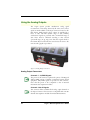
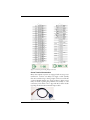
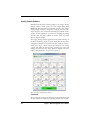
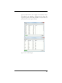
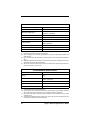
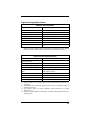
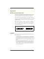
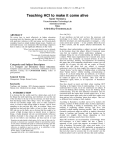
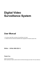
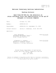
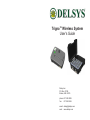
TrignoTM Wireless System
User’s Guide
Delsys Inc.
P.O. Box 15734
Boston, MA 02215
phone: 617 236 0599
fax: 617 236 0549
email: [email protected]
web: www.delsys.com
TM
TRIGNO Wireless System
User’s Guide
October 2010 Edition
PM-W01
Copyright © 2010 by Delsys Incorporated
Specifications and procedures outlined in
this document are subject to change
without notice.
Delsys Logo, EMGworks, and Myomonitor
are Registered Trademarks of Delsys
Incorporated.
MAN-012-2-0
Table of Contents
Table of Contents ....................................................................... 1
Important Information ................................................................. 3
Intended Use........................................................................ 3
Contraindications ................................................................. 3
Technical Service and Support ............................................ 3
Warnings and Precautions ................................................... 4
Device Information ............................................................... 5
Disclaimer ............................................................................ 7
Limited Warranty .................................................................. 7
System Requirements.......................................................... 7
TrignoTM Wireless EMG System Overview ............................... 8
Wireless EMG Sensor.......................................................... 8
Sensor LED Indicator Status ......................................... 9
Base Station......................................................................... 9
Power Supply ..................................................................... 10
Getting Started with the TrignoTM System............................... 11
Powering the Base Station................................................. 11
Connecting the Base Station ............................................. 11
Charging the Sensors ........................................................ 11
Turing the Sensors ON ...................................................... 13
Turning the Sensors Off ..................................................... 13
Configuring the Trigno System ................................................. 14
Software Installation and Configuration ............................. 14
Trigno System Information ................................................. 15
Trigno System Settings ............................................... 17
Trigno Sensor Status Console ........................................... 18
Using the Wireless EMG Sensors ............................................ 19
Orienting the EMG Sensors on the Skin ............................ 19
Cleaning the Sensor Site ................................................... 19
Applying the Trigno Adhesive Skin Interfaces ................... 19
Sensor Pairing ................................................................... 20
Sensor Factory Calibration ................................................ 21
Smart Sensors ................................................................... 22
Sensor Modes .................................................................... 22
Data Collection................................................................... 22
Using the Analog Outputs......................................................... 24
Analog Output Connectors................................................. 24
Channels 1 - 16, EMG Signals .................................... 24
Channels 1-64, all Signals........................................... 24
Screw Terminal Connections....................................... 25
Analog Output Software ..................................................... 26
Test Panel ...................................................................
Sensor Modes .............................................................
Using Tandem Trigno Systems ................................................
Initial Connectivity........................................................
Communication Frequencies.......................................
Synchronization ...........................................................
User Interface ..............................................................
Maintenance and Care .............................................................
Trigno Sensors...................................................................
Trigno Base Station ...........................................................
Specifications ...........................................................................
Trigno Sensors...................................................................
Trigno Recharging Base Station ........................................
Appendix I.................................................................................
Mains Isolation ...................................................................
Appendix II................................................................................
DC-A22 Unterminated Output Cable .................................
Installation ..........................................................................
DC-A22 Conductor Assignments .......................................
26
28
29
29
29
29
30
31
31
31
33
33
35
36
36
37
37
37
38
Important Information
Intended Use
The TrignoTM Wireless EMG Systems are designed for research,
investigational and scholarship purposes only. Delsys® products are
not intended for measurement purposes or for use in the treatment
and diagnosis of humans.
Rx ONLY
Contraindications
DO NOT USE on Patients with implanted electronic devices of any
kind, including cardiac pace-makers or similar assistive devices, electronic infusion pumps, and implanted stimulators.
DO NOT USE on irritated skin or open wounds.
DO NOT USE on Patients with allergies to Silver.
Technical Service and Support
For information and assistance visit our web site at:
www.delsys.com
Contact us at:
E-mail: [email protected]
tel: (617) 236 0599
3
Warnings and Precautions
Consult all accompanying documents for precautionary statements
and other important information.
Consult accompanying user’s guide for detailed instructions.
Keep the device dry. The presence of liquids may compromise the
safety features of the device.
Handle with care.
Sensitive electronic device. Avoid static discharges. Do not operate or
store near strong electrostatic, electromagnetic, magnetic or radioactive fields. Interference from external sources may decrease the signalto-noise ratio or result in corrupted data.
Connect only to Delsys-approved devices.
Connecting a patient to high-frequency surgical equipment while
using Delsys EMG systems may result in burns at the site of the EMG
sensor contacts.
Immediately discontinue device use if skin irritation or discomfort
occurs.
Immediately discontinue device use if a change in the device’s performance is noted. Contact Delsys technical support for assistance.
Delsys Inc. guarantees the safety, reliability, and performance of the
equipment only if assembly, modifications and repairs are carried out
by authorized technicians; the electrical installation complies with the
appropriate requirements; and the equipment is used in accordance
with the instructions for use.
Device contains a Lithium-Polymer battery. Do not damage, crush,
burn, freeze or otherwise mishandle the device. Recharge only with the
approved power supply and recharger.
Trigno Systems should be stored and operated between 5 and 50
degrees Celsius due to the presence of an internal Lithium Polymer
rechargeable cell. Storing or operating the device, and consequently
the cell, outside of this temperature range may compromise the integrity and the safety features of the cell.
4
TrignoTM Wireless System User’s Guide
Device Information
Complies with Requirements put forth by the Medical Device Directive 93/42/EEC. Class I device, Annex VII.
Type BF device (IEC 60601-1).
Isolated device, (Class II, IEC 60601-1)
Do not dispose this product with house waste. Contact Delsys Inc. for
instructions on responsibly disposing this device. This product should
not be mixed with other commercial wastes.
Date of Manufacturing (appears on device)
Serial Number (appears on device)
EC
REP
EMERGO EUROPE
Molenstraat 15
2513 BH, The Hague
The Netherlands
Authorized Representative
DELSYS INC.
650 Beacon St.
Boston MA 02215
USA
Manufacturer
FCC ID: W4P-SP-W02 (Trigno Base Station)
FCC ID: W4P-SP-W01 (Trigno Sensor)
IC: 8138A-DST01 (Trigno System)
This device complies with Part 15 of the FCC Rules. Operation is subject to the following two conditions: (1) This device may not cause
harmful interference. and (2) this device must accept any interference
received, including interference that may cause undesired operation.
This product complies with FCC OET Bulletin 65 radiation exposure
limits set forth for an uncontrolled environment.
Operation is subject to the following two conditions: (1) This device
may not cause harmful interference. and (2) this device must accept
any interference received, including interference that may cause undesired operation.
5
Changes not expressly approved by Delsys Inc.could void the User’s
authority to operate the equipment
To reduce potential radio interference to other users, the antenna type
and its gain should be so chosen that the equivalent isotropically radiated power (EIRP) is not more than that required for successful communication.
This equipment has been tested and found to comply with the limits
for a Class B digital device, pursuant to Part 15 of the FCC Rules.
These limits are designed to provide reasonable protection against
harmful interference in a residential installation. This equipment generates, uses, and can radiate radio frequency energy and, if not installed
and used in accordance with the instructions, may cause harmful interference to radio communications. There is no guarantee that interference will not occur in a particular installation. If this equipment does
cause harmful interference to radio or television reception, which can
be determined by turning the equipment off and on, the user is encouraged to try to correct the interference by one or more of the following
measures:
• Reorient or relocate the receiving antenna.
• Increase the separation between the equipment and receiver.
• Connect the equipment into outlet on a separate circuit.
6
TrignoTM Wireless System User’s Guide
Disclaimer
DELSYS INC. makes no warranties, express or implied, as to the
quality and performance of this product including but not limited
to, any implied warranty of applicability for other than research
uses by qualified individuals. DELSYS INC. shall not be liable to
any person for any medical expenses or any direct or consequential
damages resulting from any defect, failure or malfunction, whether
a claim for such damages is based upon theory of warranty, contract, tort or otherwise. No representative, agent, or licensed practitioner is authorized to waive this disclaimer. DELSYS INC. makes
no diagnosis or prescription by virtue of anything about this product.
Limited Warranty
The TrignoTM Wireless EMG Systems are warranted against failure
of materials and workmanship for a period of 1 year from the date
of delivery, provided that the product is given proper care and has
not been subject to abuse during this period. This warranty is in
lieu of all other warranties expressed or implied. Operation of this
device outside specifications determined by DELSYS INC. or use
with any other input devices other than DELSYS INC. sensors
constitute an invalidation of this limited warranty. This warranty is
not transferable.
System Requirements
• EMGworks 4.0.2 or later
• Windows 7, 32 bit operating systems only. Alternate OS:
Windows Vista or Windows XP with service pack 3.
• One USB 2.0 port
• At least 2.0 GHz processor clock speed
• At least 2 GB system memory
• 1280x1024 (SXGA) display resolution or better
• 1 GB hard disk storage
• Users of Windows 7 and Vista can simply ensure that they have
a Windows Experience Index of 4.0 or greater.
7
TrignoTM Wireless EMG System Overview
The TrignoTM Wireless EMG System is a high-performing device
unparalleled in its sophistication, its reliability and its ease-of-use.
Each EMG sensor has a built-in triaxial accelerometer, a
guaranteed transmission range of 40 m and a rechargeable battery
lasting a minimum of 7 hours. The system is capable of streaming
data to EMGworks Acquisition and Analysis software, and of
generating 16 EMG and 48 accelerometer analog channels for
integration with motion capture and other 3rd party data
acquisition systems. Full triggering features further expand the
possibility for integration with additional measurement
technologies.
Wireless EMG Sensor
Each Trigno Sensor is equipped with the following features:
•
•
•
•
•
•
•
•
•
•
•
•
•
•
•
•
transmission range of 40m
inter-sensor latency < 500us (< 1 sample period)
self-contained rechargeable battery
EMG signal bandwidth 20- 450 Hz
EMG signal sampling rate up to 4000 samples/sec
EMG baseline noise of <750 nV RMS
CMRR > 80dB
16-bit EMG signal resolution
integrated triaxial accelerometer
software selectable accelerometer sensitivity of ± 1.5g or ±6g
LED User feedback
battery charge monitoring and status indicator
environmentally sealed device
proven parallel bar electrode technology
contoured sensor-skin interface for maximum signal stability
auto shutoff
Inertial Sensing Axes
EMG Electrodes
Figure 1. Trigno wireless 4-channel sensor.
8
TrignoTM Wireless System User’s Guide
Sensor LED Indicator Status
Status
Data Streaming
Scanning
Pairing Successful
Pairing Unsuccessful
Mode Switch
Firmware Update
Battery Charging
Charging Complete
Charging Error
Sensor Off
LED Behavior
Flashing green, 1 Hz
Alternating green/amber flash, 1Hz
Rapid green flashing, 3x, button depressed
Rapid red flashing, 3x, button depressed
Rapid green flashing, 3x
Rapid green flashing, 3x
Solid amber, in cradle
Solid green, in cradle
LED off, sensor in cradle, cradle powered up
LED off
LED
Base Station
7
2
1
3
6
5
4
Figure 2. Trigno Base Station.
1
Wireless Sensor
5
Analog Output Connectors
2
Base Station
6
Trigger Port
3
USB Port
7
Antenna
4
Power Jack/Power Supply
8
EMGworks Software
Each Base Station is equipped with the following features:
•
•
•
•
•
•
•
•
recharging cradle for 16 sensors
high speed USB communication with PC
64-channel analog output connector (16 EMG, 48 ACC)
± 5V analog output range
detachable antenna
full trigger capability (Start/Stop, Input/Output)
communication & power feedback LEDs
convenient carry case design
9
Power Supply
Trigno Systems are equipped with an isolated medical grade power
supply. The green power LED on the base station will illuminate
when power is connected to the Base Station. The power supply is
provided with interchangeable country-specific plug adapters. The
power supply can be conveniently stored in the Base Station storage space when the system is not in use.
Figure 3. Trigno SC-P05 International Medical Power Supply
Trigno System are specifically designed and approved to
function only with the Power Supply provided. Power Supply
substitutions constitute a violation of the medical safety
approvals and will void the warranty.
If using a mains-powered PC then an additional isolation
transformer is required for medical compliance to IEC60601-1.
Refer to Appendix I for further details. No PC isolation is
required for operation on a battery-powered laptop.
10
TrignoTM Wireless System User’s Guide
Getting Started with the TrignoTM System
Powering the Base Station
Connect the Trigno power supply to the circular DC jack located
on the side of the Base Station. Energize the power supply by connecting it to a Mains outlet or to an isolation transformer. Ensure
that the PC to be used with the Base Station is connected to the
same isolation transformer. Please refer to Appendix I for clarification on using an Isolation Transformer. The power LED on the
Base Station will illuminate anytime power is applied. Ensure that
the Base Station antenna is securely attached to the antenna connector.
Figure 4. Connecting the Trigno Base Station power supply.
Connecting the Base Station
The Trigno Base Station communicates with a PC through the
USB link. It is important to install the EMGworks software prior
to connecting the Base Station to the PC. If this is not done, the
“Found New Hardware” dialog will appear, and Windows will
prompt for a driver location. Cancel this dialog and install EMGworks from the Delsys DVD in order to register the Trigno drivers
with the operating system. Once the software is correctly installed,
the PC will automatically detect the Trigno Base Station when it is
connected to the USB port.
Charging the Sensors
Before using the system, the sensors should be fully charged by
placing them in the Base Station cradle slots. Ensure the Base Station is powered and that the green power LED is illuminated.
When charging, the sensor LEDs will illuminate to an amber color.
Once the sensor battery is fully charged the sensor LED will turn
11
green. A blinking LED indicates an incomplete charge. Remove
the sensor from the device and let it stand for 5 minutes. Cycle
power on the Base Station and re-dock the sensor to restart the
charge cycle. A complete charge cycle from a fully depleted sensor
takes approximately 2.5 hours.
Do not force the sensors into the recharging cradles of the Base
Station. The sensors are keyed so that they can only be inserted
in one orientation. Check the sensor orientation and check for
obstructions in the cradle if physical resistance is met while
cradling the sensors.
Recharge only with the approved power supply (SC-P05)
originally included with the system. Charging with any other
power supply may damage the device and will void the
warranty.
Charge
Complete
Charging
Figure 5. Sensor LED feedback for battery charging status.
12
TrignoTM Wireless System User’s Guide
Turing the Sensors ON
Trigno Sensors are turned on by depressing the rubber button for
approximately one second. The green LED on the sensor will
immediately begin to flash, and begin searching for a Base Station
that has been properly paired and is within its range. If no Base
Station is found, the LED will alternate between amber and green,
indicating that it does not have an established communication link.
As soon a link is established with the Base Station, the sensor LED
will flash green approximately once per second, indicating that data
are streaming.
Figure 6. Turning the Trigno Sensor “ON”.
Turning the Sensors Off
There are several mechanisms for turning the Trigno sensors off,
described as follows:
• Send an “off ” command via software
• Dock the sensor in an active cradle
• 5 minute time-out if no base is linked
• Hold sensor button for approx. 20 sec.
13
Configuring the Trigno System
Software Installation and Configuration
The Trigno EMG system is controlled by a PC via the USB port
and thus requires specialized software. They system is shipped with
a Delsys Software DVD containing both EMGworks Signal Acquisition and Analysis Software, and the Trigno Analog Output software for use with 3rd party data acquisition systems.
Refer to the “Acquiring and Plotting Data” video tutorial
(provided on the DVD) for a brief introduction to configuring the
EMGworks software with the Trigno system.
When editing a configuration in EMGworks, the hardware options
for the base station can be set in the Hardware node of the
Configuration Tree, after selecting the Trigno as the primary A/D
device for that configuration. When using the Trigno Analog
Output application, these options can be set by clicking the
Configure button.
Figure 7. Selecting the Trigno system as the primary A/D device in the
Hardware node of the Configuration Tree.
14
TrignoTM Wireless System User’s Guide
Trigno System Information
The Information tab in the window relays data pertaining the to
system settings.
Figure 8. Trigno Wireless System information. If multiple bases are connected,
the settings for each base are shown on a separate, top level tab.
Transmission Frequencies
Wireless communication occurs on varieties of
frequencies throughout the acceptable 2.4 GHz
spectrum. Four frequency sets are available (“A”, “B”, “C”
and “D”). These should only be changed if wireless
communication is poor for the default set “A”. Poor
communication occurs if nearby sources are interfering
with the operating frequencies, or if there is significant
path loss on the operating frequencies. After changing
communication frequencies, all sensors must be re-paired.
Firmware Version
Delsys may occasionally release firmware upgrades to
improve and evolve the functionality of Trigno Systems.
The current firmware version is shown here.
Serial Number
Each Trigno Base Station has a unique serial number and
identifier address which is shown here.
Network Size
Indicates the number of sensors supported by this base.
15
Launch Test Panel
Places the Trigno Base Station in a test mode for verifying
the analog output connections. Each of the 64 analog
output channels is configured to produce a unique
sinusoid which can be verified by properly sampling these
channels with a third party data acquisition system. Refer
to the “Using Analog Outputs” section of this guide.
Refresh
This button refreshes the status information.
Copy
Copies the data the in the Information tab to the
clipboard.
16
TrignoTM Wireless System User’s Guide
Trigno System Settings
The Settings tab in the Trigno Configuration window allows
several system parameters to be modified as needed.
Figure 9. Configuring Trigno Sensor Settings
Frequency Set
Use this setting to change the frequencies being used for
wireless communication. The default set is “A”. The
frequency set should only be changed if nearby sources
are interfering with Trigno communications or the
particular operating environment is causing significant
path loss on the current frequency set. Note that
changing the communication frequency set will require
sensor re-pairing (see section on Trigno Sensor Status).
Frequencies within the sets are defined by the system and
cannot be changed by the User.
Audible Warnings
This option will generate an audible “ping” along with a
small message, whenever a sensor falls out of range or it’s
battery is excessively low.
17
Trigno Sensor Status Console
A Status console for Trigno Sensors is available when operating
EMGworks and when operating the Trigno system in Analog
Output mode. The console tracks all Trigno sensors in the system
in real-time, relaying their on/off state, their battery charge level
and their communication quality in the network. Additionally, this
console can send an “off” command to all sensors, and hosts the
sensor pairing function.
A compact display of this information is accessible in EMGworks
by hovering over the notification area icon for the Trigno
hardware. The full dialog is displayed by double-slicking this icon.
Figure 10. The Trigno Sensor Status Console offers real-time sensor feedback.
A) data acquisition status, B) battery charge state, C) sensor number, D) sensor
power, E) wireless signal strength, F) sensor pairing, G) off command.
18
TrignoTM Wireless System User’s Guide
Using the Wireless EMG Sensors
Orienting the EMG Sensors on the Skin
Trigno EMG Sensors are fitted with 4 silver bar contacts for
detecting the EMG signal at the skin surface. It is crucial that the
orientation of these bars be perpendicular to the muscle fibers for
maximum signal detection. The top of the sensor is shaped with an
arrow to aid in the determination of this orientation. The arrow
should be placed parallel to the muscle fibers underneath the
sensor. The sensor should also be placed in the center of the muscle
belly away from tendons and the edge of the muscle. The sensor is
easily attached to the skin using the Delsys Adhesive Sensor
Interface.
muscle-fiber direction
Figure 11. EMG Sensors must be properly oriented with the muscle fibers.
Align the sensor’s arrow with the direction of the underlying muscle fibers.
Cleaning the Sensor Site
Prior to affixing the EMG sensor on the surface of the skin, the
sensor site must be properly cleaned to remove dry dermis and any
skin oils. Wiping the skin prior to sensor application is critical. If
excessive hair is present, it will also be necessary to shave the site.
In cases where the skin is excessively dry, it may be useful to
dislodge dry skin cells by dabbing the site with medical tape. The
dry cells will attach the tape’s adhesive when it is removed. Be sure
to wipe with isopropyl alcohol to remove any adhesive residue that
may remain.
Applying the Trigno Adhesive Skin Interfaces
Trigno System are supplied with specially-designed adhesive
interfaces to simplify sensor attachment. These hypo-allergenic
interfaces are manufactured from medical grade adhesive approved
for dermatological applications. Usage of the interface promotes a
19
high quality electrical connection between the sensor bars and the
skin, minimizing motion artifacts and the ill-effects of line
interference. To ensure a strong bond with the skin, it is advised to
remove excessive hair and wipe the skin area and the EMG Sensor
with isopropyl alcohol to remove oils and surface residues. Allow
the skin to dry completely before applying the interfaces.
Adhesive Sensor Interfaces are for single use only.
Immediately discontinue use if skin irritation or discomfort
occurs.
All Adhesive Sensor Interfaces and Reference
Electrodes are for single use only. Discard after using. Reseal
storage bag to maintain freshness.
Sensor Pairing
Trigno sensors communicate with a custom wireless protocol that
links each sensor to a unique Base Station. This linking process is
known as sensor “pairing”, and is initiated through the “Pair”
command.
1.
Initiate sensor pairing in software.
When using EMGworks, initiate pairing by right-clicking
the Trigno hardware icon in the system notification area,
and selecting the appropriate menu item.
Figure 12. Location of the Trigno hardware icon in the system notification
area, and the pairing menu item.
20
TrignoTM Wireless System User’s Guide
When using Trigno Analog Output, click the “Pair”
button on the Sensor Status Console.
Figure 13. Pair button in the Sensor Status Console.
2.
Complete the pairing process by depressing the desired sensor
button for a minimum of 3 seconds. Successful pairing will
result in 3 green LED flashes on the sensor, and a confirmational message in the software.
Figure 14. Complete the process by depressing the sensor button for 3 sec.
Trigno systems are shipped with all sensors appropriately paired.
Sensor pairing is typically needed if sensors are being replaced
within the network group, when the communication frequency
sets are changed, and after a firmware upgrade is performed.
Sensor Factory Calibration
The system stores calibration information for sensors which have
been paired with it. When collecting data with EMGworks, this
calibration information is used to accurately display measured
values, in many cases without the need for a user-initiated manual
calibration.
After a pairing operation is completed, the system automatically
searches for pre-existing factory calibration data on the particular
sensor. If the sensor has never been paired with the system (for
example, in the case of a new additional sensor), the software will
prompt the user to enter factory calibration data, which can be
obtained from Delsys. Factory calibration data are a string a
numbers and letters which encode the calibration values for a
21
specific sensor. Factory calibrations are specific to a single sensor
and will not be accepted by the software for use on another sensor.
At any time a nominal, “default” calibration may be selected for a
sensor, or the specific factory calibration may be re-entered. This
feature is accessed by re-pairing the sensor.
Figure 15. Factory Calibration Prompt. The calibration can be either autodetected, or entered manually if the sensor is being paired for the first time.
Smart Sensors
After pairing, the association of sensors to the base station is
retained for all future uses. Any configuration in EMGworks can
be made to reflect the last paired set of sensors by clicking the
“Refresh Smart Sensors” button in the “Add Sensors” pane in
EMGworks. When data collection starts, the software will verify
that the sensors currently communicating match those used in the
configuration. If there is a mismatch, cancel the recording and repair the sensors.
Sensor Modes
Each Trigno sensor can operate in one of 4 possible data collection
modes, which determines the type of data being collected. When
using EMGworks, the sensor mode can be set on the sensor
settings pane for each sensor. Note that the number of modes
available is determined by the Trigno sensor type.
Figure 16. Setting sensor modes in EMGworks.
Data Collection
Refer to the EMGworks documentation (accessible in the Help
menu of the software) for detailed instructions on setting up data
22
TrignoTM Wireless System User’s Guide
collection in EMGworks. Whenever data are collected in EMGworks, the analog outputs on the base station are also active, so it is
possible to collect data in EMGworks and in a secondary data
acquisition system simultaneously.
23
Using the Analog Outputs
The Trigno System provides simultaneous analog signal
reconstruction of data being detected by all active sensors. These
signals are made available on the 68-pin connectors located on the
Base Station. EMG signals at these outputs are amplified by a
factor of 909, with full dynamic range of ±5V. Similarly
accelerometer signals are presented with a nominal full range of
±5V. These must be calibrated according to their selected
operational range (±1.5g, ±6g). Note that these signals exhibit a
fixed 48ms delay from the time the sensor detects the event to the
time the analog signal is reproduced.
Figure 17. Analog Output connections.
Analog Output Connectors
Channels 1 - 16, EMG Signals
The pinout of this connector replicates the pinout of the Bagnoli
desktop EMG systems to facilitate connectivity between shared
equipment. Only EMG signals are provided on this connector.
Note that this pinout is also compatible to that of National
Instruments data acquisition modules.
Channels 1-64, all Signals
This connector makes available all 64 analog output channels in
the 68-pin connector. This connector is compatible with some 80channel data acquisition modules from National Instruments.
24
TrignoTM Wireless System User’s Guide
Figure 18. Pinouts of the Analog Output connectors.
Screw Terminal Connections
Many data acquisition systems are equipped with screw-type wire
terminations. In these cases Delsys can supply a cable assembly
that mates with the Trigno Analog Output connectors and breaks
out the individual channels onto single conductors. Please contact
Delsys for details regarding this particular wire assembly or other
connectivity needs. Please refer to Appendix II for further details
regarding the DC-A22 Unterminated Output Cable.
Figure 19. DC-A22 Unterminated Output Cable.
25
Analog Output Software
Included with the Delsys software package is the Trigno Analog
Output software, which operates on a PC independently from
EMGworks Data Acquisition and Analysis software. The Trigno
Analog Output Software is designed to configure and control the
Trigno System so that it becomes a full analog instrument. In this
scenario, all data acquisition is performed by sampling the analog
channels with 3rd party acquisition systems, often used with
Motion Capture Systems.
The Trigno Analog Output application must remain running on
the PC for the analog outputs to remain active. The wireless sensor
configuration window is accessible from the “configure” button.
“Start” and “Stop” controls activate and deactivate the analog
outputs, and define the Start and Stop output trigger events. All
settings are locked once the “Start” button is depressed, and can
only be changed after the “Stop” button is pressed.
Figure 20. Trigno Analog Output software.
Test Panel
The Test Panel is used to verify the analog signal connections with
the data acquisition module by outputting predefined and unique
26
TrignoTM Wireless System User’s Guide
signals on each channel. The test signals are sinusoidal in nature
and defined by an amplitude, a frequency and an offset. The
expected outputs for each analog channels are listed in the Test
Panel window once the option is slected.
Figure 21. The Test Panel Signals.
27
Sensor Modes
In the Analog Output application, the sensor mode is controlled
on the Mode Control tab of the Configuration dialog.
When using the Analog Output application, the 4 modes are
determined by the selection of the check boxes for mode A and
mode B on each sensor. These settings are independent from the
range settings in EMGworks.
Modes for Trigno Sensor (type 00)
Mode A
Mode B
Interpretation
+/- 1.5 g ACC Range
+/- 6 g ACC Range
+/- 1.5 g ACC Range
+/- 6 g ACC Range
Figure 22. Setting sensor modes in the Analog Output application.
28
TrignoTM Wireless System User’s Guide
Using Tandem Trigno Systems
Two Trigno systems may be used in tandem, connected to the
same computer as a synchronized 32 sensor, 128 channel system.
Initial Connectivity
To use two Trigno systems in a tandem configuration, connect the
USB cable from each base station to the same computer. If using
EMGworks, also connect the Trigger Cross-Over Cable (DC-C02)
between the trigger ports on the two base stations. After connecting the USB cables and powering each base station, launch either
the Trigno Analog Output application or EMGworks. Note that
the trigger cross-over cable will work irrespective of orientation.
Figure 23. Installation of the Trigger Cross-Over cable to synchronize two base
stations when used with EMGworks.
Communication Frequencies
When the software detects the presence of two bases connected to
the computer, the frequency sets on each base are automatically
changed to allow the simultaneous communication of 32 sensors.
The user is required to re-pair each sensor to use these new
communication frequencies. Similarly, when reverting to the use of
a single base, the communication frequency set will be restored to
the option selected by the user (Set A, B, C, or D) and the sensors
must again be re-paired.
Synchronization
All channels of data collected in a tandem configuration are fully
synchronized between the two bases.
29
User Interface
User interface options are expanded to reflect the presence of
additional sensors.
Figure 24. The Status Console when tandem bases are used.
30
TrignoTM Wireless System User’s Guide
Maintenance and Care
Trigno Sensors
Trigno sensor are encased in a sealed polycarbonate enclosure. The
following points should be kept in mind when handling the
sensors.
• All sensors should be visually inspected before each use to
ensure that no mechanical deterioration has occurred.
• The sensors can be cleaned and sterilized with a damp cloth and
mild detergent, or with 70% isopropyl alcohol swabs. Ensure
that the sensor contacts remain clean at all times for proper
operation.
• While the sensors are sealed and are water-resistant, these
should never be completely submerged in any liquid. They are
design to be used on damp skin surfaces and in the presence of
sweat without compromise to safety, sensor integrity or operation.
• The sensor contacts are made of pure silver and are quite soft.
Care should be taken to preserve the integrity of these contacts.
Do not scrape or dent these contacts.
• Handle the sensors with care: do not drop them on the ground
or step on them.
Do not submerge the sensors in any liquid under any
circumstance.
The sensors contain sensitive electronic circuitry. Static
discharges and intense magnetic fields should be avoided to
prevent the risk of irreparable damage to the sensors.
Trigno Base Station
The Trigno System is designed to provide years of reliable service
when proper care is followed. While the Base Station enclosure is
made of durable plastic, the following points should be kept in
mind during its use and handling:
• The device and its accessories should be visually inspected
before every use to ensure that no mechanical deterioration has
occurred.
• The Base Station can be easily cleaned with a 70% solution of
isopropyl alcohol if necessary. DO NOT EXPOSE THE BASE
STATION TO ANY LIQUID. IT IS NOT A SEALED
DEVICE.
31
• The units are not shockproof and should not be dropped or be
subjected to excessive forces or accelerations.
The recharging Base Station is not water-resistant. Under no
circumstance should this unit be exposed to water or any other
type of liquids.
32
TrignoTM Wireless System User’s Guide
Specifications
Trigno Sensors
GENERAL SPECIFICATIONS
Typical Operating Range
(1)
40 m
Transmission Source
2.4 GHz, 1 mW
Power Consumption
<60 mW
Case Dimension
27 x 37 x 15 mm
Case Material
medical-grade polycarbonate
(2,3)
Full-charge Operation Time
8 hours
Recharge Time
<2.5 hours
Mass
< 15g
Auto Shut-down timer
Temperature Range
(1)
(2)
(3)
(4)
(4)
300 seconds
5 - 50 degrees Celsius
Range is characterized in open office environments. Interfering RF sources in the 2.4GHz
spectrum, as well as absorptive objects occluding the RF communication path may degrade
transmission distance. Stated range can be exceeded under favorable RF conditions.
Battery duration is a function of charge and discharge conditions. Optimal battery
performance is obtained when the device is operated at room temperature. Note that the
stated Operation Time reflects the expected performance of a fully charged new battery used
in a sensor that is transmitting data. Operation Time is expected to decrease as a function of
charge cycles, and when the sensor is searching for a network.
80% of original battery capacity is maintained after 300 discharge/recharge cycles. This
value represents a typical expectation under ideal conditions. Actual performance will vary
depending on usage conditions.
Operation beyond these temperature limits may damage the rechargeable battery.
33
EMG SENSOR SPECIFICATIONS
Range
(1)
11 mV (r.t.i.)
Resolution (EMG Signal)
(2)
168 nV/bit
Bandwidth (EMG Signal)(3
20±5 Hz, >40 dB/dec
450±50 Hz, >80 dB/dec
Passband Ripple(3
<2%
Overall Channel Noise
(4)
<0.75uV
CMRR
>80 dB
Sampling Rate(5)
2000 samples/sec
4000 samples/sec
Number of Contacts
4
Contact Dimension
5 x 1 mm.
Contact Material(6)
99.9% Silver
(1)
(2)
(3)
(4)
(5)
(6)
Range is specified for the input of the EMG sensor and is samples with 16 bits
Resolution is specified for the input of the sensor.
Filter is designed as a maximally flat Butterworth to preserve EMG signal amplitude and
phase linearity.
Input-referred noise is calculated as a root mean square over a 5 second window sampled at
2kHz.
EMG signal sampling rates are intrinsic to the sensor and cannot be changed beyond the two
stated rates, which are software selectable.
Sensor skin contacts are made from pure silver and should not be used if allergic reactions to
silver are expected or found to occur.
ACCELEROMETER SPECIFICATIONS
Number of Axis
3
Range(1,2)
±1.5g
±6g
Resolution(2)
0.016 ± 0.001 g/bit
0.063 ± 0.005 g/bit
Offset Error(3)
±0.2g
Bandwidth
DC - 50±5 Hz, 20dB/dec
Sampling Rate(4)
148.1 / 296.3 samples sec
(1)
(2)
(3)
(4)
34
Accelerometer range is software selectable.
Accelerometer output is sampled with 8 bits over full range (±2g, ±7g). Readings exceeding
the nominal range of ±1.5g and ±6g may be non-linear and are not guaranteed.
Offset errors can nulled in software by using a calibration routine that references the normal
gravitation force.
Accelerometer sampling rates are intrinsic to the sensor and cannot be changed beyond the
two stated rates, which are software selectable.
TrignoTM Wireless System User’s Guide
Trigno Recharging Base Station
GENERAL SPECIFICATIONS
Typical Operating Range
40 m(1)
Transmission Source
2.4 GHz, 1 mW
Power Consumption
<10W
Sensor Recharge Time
< 2.5 hours
USB type
USB 2.0 compliant, high speed
Temperature Range
5 - 50 degrees Celsius
Maximum number of Sensors
16
Inter-sensor delay
<500 us
Dimensions
276 x 241 x 127 mm
(1)
Range is characterized in normal office environments. Interfering RF sources in the 2.4GHz
spectrum, as well as absorptive objects occluding the RF communication path may degrade
transmission distance. Stated range can be exceeded under favorable RF conditions.
ANALOG OUTPUT SPECIFICATIONS
Number of outputs
Signal group delay
16 EMG, 48 Accelerometer
(1)
EMG Signal Range
48 ms
±5 V
Effective EMG Signal Gain(2)
909 V/V
Accelerometer Signal Range
±5 V
Nominal Accelerometer Signal
Gain(3)
2.42 V/g @ ±1.5g range
0.62 V/g @ ± 6 g range
Channel Offset
±100 mV (max)
Baseline Noise
0.5mV RMS
Passband Ripple(4)
<2% with Sin(X)/X correction
Connector Type
SCSI-68, Type II
(1)
(2)
(3)
(4)
Delay from sensor event to analog output is fixed for all channels, and referenced as a
“group delay”.
This parameter relates the detected voltage input at the sensor to the reproduced voltage at
the EMG channel output.
This parameter relates the nominal uncalibrated voltage differential for an inertial
displacement of 1 g.
Sin(X)/X correction is applied to each channel for cancelling the distorting effects of the DAC
sampling process.
35
Appendix I
Mains Isolation
The Trigno Base Station is provided with Medical Grade isolated
power supply which is compliant with IEC60601 series of
harmonized standards for Medical Devices. However, full
compliance with IEC60601-1 Basic Safety for Medical Devices
requires that the PC operating the software be isolated as well. This
stems from the basic requirement to have all patients electrically
isolated from equipment within their reach, and since the PC
running the Trigno Software is conceivably within their reach, it
too must be isolated.
Delsys does not supply isolation transformers for Personal
Computers and their peripherals.
Delsys recommends model IS1000HG manufactured by Tripp
Lite (www.tripplite.com) for this task. This device is a medial
grade isolation transformer capable of delivering up to 1000 W.
A smaller similar version for 500W is also available (IS500HG).
Similar products compliant with IEC60601-1 are acceptable.
36
TrignoTM Wireless System User’s Guide
Appendix II
DC-A22 Unterminated Output Cable
The DC-A22 Unterminated Output Cable provides access to all
64 analog output channels from the Trigno System on discrete
wires for data acquisition systems with screw-type terminations.
The DC-A22 cable connects directly to the output connector
labeled "1-64"on the Trigno System and terminates in 67 signal
conductors with pre-stripped ends (64 analog output signals and 3
GND conductors).
Each conductor employs a unique color scheme to identify its
signal. The conductor jacket is the primary color, and it is marked
with a secondary color. An example of the coloring scheme is
shown in Figure 25 below.
White / Black
Black / White
Figure 25. Wire color scheme example.
Installation
Refer to Figure 26 for installing the DC-A22 cable. Please observe
the following points:
• Connect the GND wires to the data acquisition system ground
for analog inputs. It is recommended to twist all three wires
together and connect these to a common ground point on the
measurement system to avoide the risk of creating ground
loops.
• Ensure that any unused conductors are not exposed and will
not come into contact with each other or any other signal or
voltage potential. This can be done by clipping the bare ends
of the conductors or using heat shrink tubing or electrical tape
to enclose the bare ends.
37
DC-A22 Conductor Assignments
Trigno
Output
Trigno
Pin
Conductor Color
Primary / Secondary
Trigno
Output
Trigno
Pin
Conductor Color
Primary / Secondary
EMG 1
68
Violet / Orange
AY 9
16
Tan / Violet
AX 1
67
Blue / Orange
AZ 9
17
Tan / Gray
AY 1
33
Orange / Blue
EMG 10
49
Blue / Tan
AZ 1
34
Orange / Violet
AX 10
48
Green / Tan
EMG 2
66
Green / Orange
AY 10
14
Tan / Green
AX 2
65
Yellow / Orange
AZ 10
15
Tan / Blue
AY 2
31
Orange / Yellow
EMG 11
47
Yellow / Tan
Orange / Tan
AZ 2
32
Orange / Green
AX 11
46
EMG 3
64
Gray / Pink
AY 11
12
Tan / Orange
AX 3
63
Violet / Pink
AZ 11
13
Tan / Yellow
AY 3
29
Pink / Violet
EMG 12
45
Pink / Tan
AZ 3
30
Pink / Gray
AX 12
44
Brown / Tan
EMG 4
62
Blue / Pink
AY 12
10
Tan / Brown
AX 4
61
Green / Pink
AZ 12
11
Tan / Pink
AY 4
27
Pink / Green
EMG 13
42
Violet / White
AZ 4
28
Pink / Blue
AX 13
41
Blue / White
EMG 5
60
Yellow / Pink
AY 13
7
White / Blue
AX 5
59
Orange / Pink
AZ 13
8
White / Violet
AY 5
25
Pink / Orange
EMG 14
40
Green / White
Yellow / White
AZ 5
26
Pink / Yellow
AX 14
39
EMG 6
58
Gray / Brown
AY 14
5
White / Yellow
AX 6
57
Violet / Brown
AZ 14
6
White / Green
AY 6
23
Brown / Violet
EMG 15
38
Orange / White
AZ 6
24
Brown / Gray
AX 15
37
Pink / White
EMG 7
55
Green / Brown
AY 15
3
White / Pink
AX 7
54
Yellow / Brown
AZ 15
4
White / Orange
AY 7
20
Brown / Yellow
EMG 16
36
Brown / White
AZ 7
21
Brown / Green
AX 16
35
Tan / White
EMG 8
53
Orange / Brown
AY 16
1
White / Tan
AX 8
52
Pink / Brown
AZ 16
2
White / Brown
AY 8
18
Brown / Pink
GND
9
White / Gray
AZ 8
19
Brown / Orange
GND
22
Brown / Blue
EMG 9
51
Gray / Tan
GND
43
Gray / White
AX 9
50
Violet / Tan
NC
56
Blue / Brown
Figure 26. DC-A22 Conductor Assignments
38
TrignoTM Wireless System User’s Guide