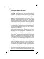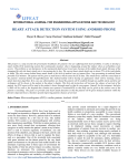
1
®
The Bagnoli-4
EMG System
100
TONE
I
REF
HI
O
REF
10K
HI
VAR
LINE
REF
100
1K
CH 3
100
1K
10K
REF
HI
VAR
LINE
100
1K
10K
VAR
LINE
CH 1
Delsys Inc.
P.O. Box 15734
Boston
MA 02215
phone: 617 236 0599
fax:
617 236 0549
email:
web:
REF
HI
[email protected]
www.delsys.com
1K
POWER
10K
VAR
LINE
Bagnoli-4 EMG System
User Manual
May 2003 Edition
Copyright © 2003, by Delsys Incorporated.
Specifications and procedures outlined in this
manual are subject to change without notice.
®
®
Delsys Logo, EMGworks , and MyoMonitor are Registered Trademarks of
Delsys Incorporated.
Bagnoli-4 EMG System User Manual
IMPORTANT INFORMATION
Intended Use
The Bagnoli EMG Systems are designed for research, investigational and scholarship purposes only. DelSys products are not intended for measurement purposes or for use in the treatment and diagnosis of humans.
Warnings and Precautions
Delsys products are not designed to be used in conjunction with any devices not
approved by Delsys Inc. Please contact Delsys for further information.
Connecting a patient to high-frequency surgical equipment while using Delsys
EMG systems may result in burns at the site of the EMG sensor contacts.
Immediately discontinue device use if skin irritation or discomfort occurs.
Immediately discontinue device use if a change in the device’s performance is
noted. Contact Delsys technical support for assistance.
Do not use Delsys products in the presence of any liquid or during conditions
where the device or the user(s) may become exposed to liquids. The presence of
liquids may compromise the safety features of the devices.
Delsys EMG amplifiers are extremely sensitive to electrical disturbances. Avoid
static discharges and electromagnetic fields.
Delsys Inc. guarantees the safety, reliability, and performance of the equipment
only if assembly, modifications and repairs are carried out by authorized technicians; the electrical installation of the relevant room complies with the appropriate requirements; and the equipment is used in accordance with the instructions
for use.
Certifications
European Community
Bagnoli EMG Systems satisfy the Essential Requirements put forth by the
"Medical Device Directive" 93/42/EEC concerning the distribution of devices in
Europe.
Compliance
Bagnoli EMG System comply in full with the relevant clauses of the following
standards:
EN60601-1:
Medical Electrical Equipment (IEC 601, UL2601)
EN60601-1-2
Electromagnetic Compatibility- Requirements and Tests
EN60601-2-40: Specification for electromyographs and evoked response equipment
EN980:
Graphical symbols for use in the labeling of medical devices
ISO10993-1:
Biological evaluation of medical devices
© Delsys Incorporated
2
Bagnoli-4 EMG System User Manual
Disclaimer
DELSYS INC. makes no warranties, express or implied, as to the quality and
performance of this product including but not limited to, any implied warranty of
applicability for other than research uses by qualified individuals. DELSYS INC.
shall not be liable to any person for any medical expenses or any direct or consequential damages resulting from any defect, failure or malfunction, whether a
claim for such damages is based upon theory of warranty, contract, tort or otherwise. No representative, agent, or licensed practitioner is authorized to waive this
disclaimer. DELSYS INC. makes no diagnosis or prescription by virtue of anything about this product.
Limited Warranty
The Bagnoli-4 systems are warranted against failure of materials and workmanship for a period of 1 year from the date of delivery, provided that the product is
given proper care and has not been subject to abuse during this period. This warranty is in lieu of all other warranties expressed or implied. Operation of this
device outside specified power supply or input voltage ranges specified by DELSYS INC. or use with any other input devices other than DELSYS INC. electrodes constitute an invalidation of this limited warranty. This warranty is not
transferable.
All devices to be returned require a return authorization number issued by DELSYS INC. All authorized returned merchandise must be shipped prepaid to
DELSYS INC. If authorization for the return of a device is given, please insure
the product in transit for any loss or damages that may occur.
Technical Support
Visit our web site at:
http://www.delsys.com
Tel: (617) 236-0599
Fax: (617) 236-0549
© Delsys Incorporated
3
Bagnoli-4 EMG System User Manual
Table of Contents
The Bagnoli-4 EMG System ..................................................................... 6
General Description............................................................................. 6
The DE-2.1 Differential Surface Electrode .......................................... 7
The DE-3.1 Double Differential Electrode (Optional) ......................... 7
The Main Amplifier Unit ....................................................................... 8
The Belt-Mounted Interface Unit ......................................................... 8
The Reference Electrode Cable .......................................................... 9
The Power Supply ............................................................................... 9
Using the Bagnoli-4 EMG System ............................................................ 9
Connecting the Power Supply ............................................................. 9
North American Power Supply ....................................................... 9
International Power Supply .......................................................... 10
Connecting the Input Signals ............................................................ 11
Connecting the Interfaced Unit and Associated I/O Cable........... 11
Connecting the EMG Surface Electrodes the Interface Unit ........ 11
Connecting the Reference Electrode ........................................... 12
Connecting the Output Signals.......................................................... 12
Using the Electrodes ......................................................................... 13
Orienting the Electrodes on the Skin............................................ 13
Using the DelSys Electrode Interface .......................................... 13
Attaching the Reference Electrode .............................................. 14
The Bagnoli-4 EMG System Controls ............................................... 15
Turning the System “ON” ............................................................. 15
Selecting the Appropriate Amplifier Gains ................................... 15
Error Detection Features ................................................................... 16
Line Interference Detector............................................................ 16
Saturation Level Detector............................................................. 16
Audible Buzzer Alarm................................................................... 17
Maintenance/Care of the Bagnoli-4 EMG System.................................. 17
The Main Amplifier Unit and Interface I/O Unit.................................. 17
The DE Series Electrodes ................................................................. 18
Troubleshooting...................................................................................... 18
Excessive Presence of Line Interference .......................................... 18
Poor Electrode-Skin Adhesion .......................................................... 21
Excessive Presence of Motion Artifact .............................................. 22
Poor or No EMG Signal at Output ..................................................... 23
© Delsys Incorporated
4
Bagnoli-4 EMG System User Manual
Overall System Check ................................................................. 23
Individual Channel Check ............................................................ 23
A/D Acquisition System Check ......................................................... 24
Excessive Presence of Channel Crosstalk ....................................... 25
System Does Not “Turn On” ............................................................. 26
The Bagnoli-4 EMG System Specifications ........................................... 27
Main Amplifier Unit............................................................................ 27
Belt Mounted I/O Unit........................................................................ 27
DE 2.1 Electrodes ............................................................................. 28
DE 3.1 Electrodes ............................................................................. 28
I/O Interface Cable............................................................................ 29
Reference Electrode Cable............................................................... 29
Glossary of Commonly Used Terms ...................................................... 30
Table of Figures
Figure 1:
Figure 2:
Figure 3:
Figure 4:
Figure 5:
Figure 6:
Figure 7:
Figure 8:
Figure 9:
Figure 10:
Figure 11:
Figure 12:
Figure 13:
Figure 14:
Figure 15:
Figure 16:
Figure 17:
Components of the Bagnoli-4 EMG System ................................... 6
The DE-2.1 Single Differential Electrode …………….……………. 7
The optional DE-3.1 Double Differential Electrode ……...……….. 8
(a) The Main Amplifier Unit …………………………………..……….8
(b) The Belt-mounted Interface Unit .………………………..……....8
(a) The Reference Electrode Cable ……………………….………..9
(b) The Interface Unit I/O Cable .…………………………….……....9
The back panel of the Main Amplifier Unit ………………..………..10
(a) The Elpac MED 144 North American Power Supply ……...…11
(b) The Ault SW172 wide input Power Supply ………………...….11
(c) The Bagnoli-4 Power Input Connector ………………………....11
Connecting the Main Amplifier Unit …………………..………….…11
The Reference Electrode ……………………..………………….....12
Signal output pinout of the D-sub 37 output connector ………......12
Electrode orientation with respect to the muscle fibers ……….....13
Application of the DelSys Electrode Interface …………………....14
Reference electrode cable used with conductive disk …………...14
The LED error detection indicators .……………...…………….....16
(a) The source of line interference in EMG signals ..………….....19
(b) The subtraction of power line-induced voltages …..………....19
(a) Typical system noise ………..………………………………....24
(b) Shorting the electrode inputs ……….………………………....24
The output of the power supply ………....……………………….....25
© Delsys Incorporated
5
Bagnoli-4 EMG System User Manual
The Bagnoli-4 EMG System
General Description
The Bagnoli-4 EMG System is designed to make the acquisition of EMG signals
hassle-free and reliable. The active electrodes are specifically designed to optimally detect EMG signals at the skin surface, while rejecting common noise signals such as motion and cable artifacts, yielding an excellent signal-to-noise ratio. Gains of 100, 1000 or 10000 can be selected for the ideal acquisition of different amplitude signals. There is as also a variable gain control available so that
any amplification factor between 100 and 10000 can be chosen. Each of the four
channels is equipped with two signal quality checks: one for the presence of line
interference in the signal and one for amplifier saturation caused by an excessive
gain setting. These errors are signaled by the illumination of yellow LEDs located on the front panel of the unit, and by an optional audio buzzer. The unit is
powered by an isolated medical grade power supply, with leakage currents less
than 10uA and safety isolated to 3750 VRMS. The integration of all these features
in a lightweight desktop unit lends the Bagnoli-4 practical in both lab and field
environments.
The Bagnoli-4 EMG System is comprised of the following items:
• four active Differential Surface Electrodes
• one Main Amplifier Unit
• one belt-mounted Interface Unit
• one Reference Electrode Cable
• one Interface Unit I/O Cable
• one Power Supply
PC with Software
DE-2.1 or DE 3.1
Differential Electrodes
A/D Cable
Reference
Electrode &
Cable
Belt-mounted
Interface Units
Class II, Type BF
Power Supply
Main Amplifier Unit
I/O Cable
Figure 1: Components of the Bagnoli-4 EMG System
© Delsys Incorporated
6
Bagnoli-4 EMG System User Manual
The DE-2.1 Differential Surface Electrode
The differential electrode subtracts EMG potentials detected at two distinct locations on the surface of the skin, directly above an active muscle. The EMG potentials are always measured with respect to the electric potential of a neutral
inactive site located away from the EMG muscle source. The electric potential
of this neutral site is commonly termed “the reference” potential, and is accessed
by the Reference Electrode.
The electrode housing is constructed with a waterproof polycarbonate plastic
case, which is internally shielded to reject ambient electrical noise. The electrode
contacts are made from 99.9% pure silver bars measuring 10 mm in length,
1 mm in diameter and spaced 10 mm apart for optimal frequency capture. It is
these contacts that detect the EMG potentials described above. The detected
signals are subtracted and then amplified before being sent along a shielded cable to the rest of the EMG system. The 5-ft electrode cable terminates in a circular connector that hosts four contacts: two for power, one for the reference potential, and one for the electrode output. This connector mates with its socket located on the belt-mounted Interface Unit.
10 mm
Muscle site
vout = v1-v2
10 mm
v1
v2
1 mm
Reference
Figure 2: The DE-2.1 Single Differential Electrode. The EMG signal is the result of the
potential difference between v1 and v2 on the skin surface.
The DE-3.1 Double Differential Electrode (Optional)
The DE-3.1 Double Differential Electrode is not included in the standard Bagnoli-4 EMG system and must be purchased separately. It is specifically designed
to reduce the presence of EMG crosstalk emanating from muscles underneath
and adjacent to the muscle of interest. The external dimensions of the electrode
and the electrode bars are identical to the standard DE-2.1 electrodes. This unit
however uses 3 bars instead of 2. It works on the principle that a signal originating from a source further away (some other muscle) will arrive at adjacent detection surfaces with less relative latency than a signal which originates from the
muscle beneath the electrode. By performing two subtractions, the signals with
short relative latency (those originating from distant sources) will cancel out.
© Delsys Incorporated
7
Bagnoli-4 EMG System User Manual
Muscle site
vout
Reference
∆v1+vx ∆v2+vx
∆v2+vx
vout = [∆v1+vx ]- [∆v2+vx ]
= ∆ v1 - ∆ v2
∆v1+vx
Figure 3: The optional DE-3.1 Double Differential Electrode. EMG crosstalk signals
originating from far sources (vx) remain relatively unchanged across the three contact
bars when compared to the EMG signals originating immediately under the bars. The vx
components are cancelled in the double differential recording. Note that the EMG potential present in the middle contact appears in both ∆v1 and ∆v2. This causes the output
amplitude of the signal to be approximately 1.5 times larger than the single differential
electrode
The Main Amplifier Unit
This desktop unit supplies power to the EMG Electrodes, receives and conditions
the signals detected by the EMG Electrodes, and provides 4 analog channel outputs which can be accessed by BNC connectors or by a D-Sub type connector.
Each channel has a selectable gain which can be set to a factor of 100, 1000 or
10000. There is also a “REF” setting, which forces the output of the channel to
the reference potential. The Main Unit filters the EMG signals to a bandwidth
between 20 Hz and 450 Hz, and checks for excessive amounts of line interference, as well as channel clipping due to over-amplified signals. The presence of
these errors is signaled via red LEDs, and through a user-enabled audio buzzer
alarm.
(a)
(b)
100
TONE
I
HI
O
LINE
100
1K
REF
10K
CH 1
HI
VAR
LINE
100
1K
REF
10K
CH 2
HI
100
1K
REF
VAR
10K
HI
VAR
LINE
CH 3
1K
REF
LINE
POWER
10K
REF
CH 4
CH 3
CH 1
VAR
Figure 4: (a) The Main Amplifier Unit. (b) The Belt-mounted Interface Unit.
The Belt-mounted Interface Unit
This is a lightweight connection box that hosts four EMG Electrodes and the
Reference Electrode cable. The EMG signals detected by the electrodes are
communicated to the Main Amplifier Unit via the Interface Unit I/O Cable, an
umbilical that also carries power to the electrodes. The unit has a clip on one
side, which allows easy fastening to waist belts or other articles of clothing.
© Delsys Incorporated
8
Bagnoli-4 EMG System User Manual
The Reference Electrode Cable
This is a single-conductor wire with a “banana” connector on one end and an
“alligator clip” on the other end. The banana plug is hosted by a receptacle located in the belt-mounted Interface Unit. The alligator clip can be connected to
any conductive adhesive patch placed on an inactive site on the body. It is important that the Reference Electrode have a high quality electrical connection
with the skin.
(a)
(b)
Figure 5: (a) The Reference Electrode Cable. (b) The Interface Unit I/O Cable.
The Power Supply
The Bagnoli-4 is equipped with one of two Medical Grade power supplies. The
domestic power supply conforms to the medical UL544 standard, and is approved by the FDA. This wall mounted supply provides a regulated 12 Volt
output for the Bagnoli-4 System, with leakage currents below 10 µA. Alternatively a wide-voltage input Medical Grade power supply is included for use in
foreign countries. This accepts inputs of from 60 to 240 Vrms at either 50 Hz or
Using the Bagnoli-4 EMG System
All input/output connections of the Main Unit Amplifier are located on the rear
panel of the assembly (shown in Figure 6), while the front panel (shown in Figure 4(a)) hosts the EMG channel controls, the error detection information and
the main power switch.
Connecting the Power Supply
The power supply is connected to the circular DIN socket on the left side of the
rear panel labeled “12 VDC”, as shown in Figure 6. Note that the connector is
polarized, so that it can only be inserted with the correct orientation. The
3-prong line-voltage plug of the power supply should be inserted in a properly
functioning and grounded power supply outlet.
North American Power Supply
Units sold in the United States and Canada are equipped with a 120 VAC, 60 Hz
regulated Medical Grade power supply manufactured by Elpac. This supply
conforms to the UL544 medical standard, the IEC 60601 medical standard and
has CSA and UL approval.
© Delsys Incorporated
9
Bagnoli-4 EMG System User Manual
!
CAUTION: Bagnoli-4 Systems fitted with the ELPAC MED 144
power supply must only be plugged into 120 VAC U.S. and Canadian receptacles. Failure to use the power supply with properly
rated receptacles may damage the system and create hazardous
situations.
International Power Supply
Units sold outside the United States or Canada are equipped with a variableinput Medical Grade power supply. The input can range from 100 to 250 VAC
and 50 to 60 Hz. This supply conforms to UL2601, CSA601 and TUV/IEC
60601-1 safety standards. The supply is fitted with a universal IEC 320 input
plug so as to accept power cables from several countries.
!
CAUTION: Always ensure that the voltage input switch on the
power supply is correctly set to accept the mains voltage of your
location. An incorrect setting may damage the power supply.
!
CAUTION: Bagnoli-4 Systems are equipped with a specially made
power supply. Using a power supply other than the one provided
may damage the system and create hazardous situations.
!
CAUTION: Always use an IEC320 power cable and properly functioning mains receptacle for powering the Bagnoli-4 EMG System.
A disconnected ground plug can result in shock hazards
INPUT
OUTPUT
4
3
2
1
12 VDC
Power Input
Connector
I/O Unit Input
Connector
D-sub 37 Signal
Output Connector
BNC Output
Connectors
Figure 6: The back panel of the Main Amplifier Unit. All power, input and output connections are made on this panel.
© Delsys Incorporated
10
Bagnoli-4 EMG System User Manual
(a)
(b)
(c)
Figure 7: (a) The Elpac MED 144 North American power supply. (b) The Ault SW172
wide input power supply. (c) The Bagnoli-4 power input connector
Connecting the Input Signals
Connecting the Interface Unit and Associated I/O Cable
The Interface Unit I/O cable bridges the portable Interface Unit with the Main
Amplifier Unit. Each end of the 25-foot cable terminates in a shielded RJ-45
connector. One end of the cable is inserted in the I/O input socket located on
the rear panel of the Main Amplifier Unit while the opposite end of the cable is
inserted in a similar socket labeled “OUTPUT” on the Interface Unit as shown
in Figure 8. The Interface Unit is equipped with a belt-clip to facilitate its attachment to the user.
Interface Unit
I/O Cable
Interface Unit
Main Amplifier Unit
shielded RJ-45
connector
Figure 8: Connecting the Main Amplifier Unit and Interface Unit via the I/O cable.
Connecting the EMG Surface Electrodes to the Interface Unit
The Bagnoli-4 EMG Unit is supplied with four DE-2.1 Surface EMG electrodes.
These plug into the receptacles labeled Ch.1 to Ch.4 on the Interface Unit.
Channel 1 and Channel 3 are located on the opposite panel of the Interface Unit
as Channel 2 and Channel 4. The connectors have a key so that they can only be
inserted with a specific orientation. The order of the electrodes can be interchanged with no consequences to the performance of the EMG System. The
electrode cables are five feet in length so that they can be placed on any part of a
typical user’s body when the Interface Unit is mounted at waist level.
© Delsys Incorporated
11
Bagnoli-4 EMG System User Manual
Connecting the Reference Electrode
The Bagnoli-4 EMG Unit is supplied with a reference electrode cable terminating in a “banana” style plug on one end, and an “alligator” clip on the other end.
The banana plug is fitted in the receptacle labeled “REF” on the Interface Unit.
The alligator clip is used to connect to the conductive adhesive tabs supplied
with the unit. The clip is used to pinch the dry edge of the adhesive electrodes,
as depicted in Figure 9.
“3M Red Dot”
conductive
electrode
“alligator” clip
“banana”
connector
electrically
neutral skin
surface
Figure 9: The Reference Electrode. The “banana-style” connector is mated with the
Interface Unit, while the “alligator” clip is used to connect to conductive adhesive electrodes.
Connecting the Output Signals
The Bagnoli-4 EMG System outputs 4 single-ended voltage signals in the ± 5
Volt range. The rear panel of the Main Unit hosts two types of output connections: 4 BNC sockets and one D-Sub 37 female connector, as shown above in
Figure 6. The BNC connections provide easy access to oscilloscope inputs,
while the 37-pin connector can be used to directly access an A/D data acquisition
system. The pinout of the D-Sub 37 connector is shown in Figure 10.
19 18 17 16 15 14 13 12 11 10 9 8 7 6 5 4 3 2 1
37 36 35 34 33 32 31 30 29 28 27 26 25 24 23 22 21 20
Pin
37
36
35
34
Signal
Channel 1
Channel 2
Channel 3
Channel 4
Figure 10: Signal pinout of the D-Sub 37 output connector .
© Delsys Incorporated
12
Bagnoli-4 EMG System User Manual
!
Note: The input impedance of any device used to connect to the
outputs of the Bagnoli-4 EMG System should be at least 1 MΩ. The
output impedance of each Bagnoli-4 EMG channel is 15 KΩ.
Using the Electrodes
Orienting the Electrodes on the Skin
The DE-2.1 Surface EMG Electrode is fitted with two silver bar contacts for
detecting the EMG signal at the skin surface. It is crucial that the orientation of
these bars be perpendicular to the muscle fibers for maximum signal detection.
The top of the electrode is stamped with an arrow to aid in the determination of
this orientation. The arrow should be placed parallel to the muscle fibers underneath the electrode as demonstrated in Figure 11. It is important that the electrode and the skin are clean and free of oil and other resides before placement of
the electrodes. It is advised to remove excessive hair from the EMG site. The
electrodes are easily attached to the skin with the DelSys Electrode Interface.
Alternatively, surgical tape may be used.
orientation
arrow
underlying muscle
DELSYS
direction of muscle fibers
Figure 11: Electrode orientation with respect to the muscle fibers. It is important that
the orientation arrow on the electrode be parallel to the underlying muscle fibers.
Using the DelSys Electrode Interface
The DelSys Interfaces are made from medical grade adhesive specifically designed for dermatological applications. Usage of the interface promotes a high
quality electrical connection between the electrode bars the skin, minimizing
motion artifacts and the ill-effect of line interference. To ensure a strong bond
with the skin, it is advised to shave excessive hairs and wipe the skin area with
isopropyl alcohol, to remove oils and surface residues. Allow the skin to dry
completely before applying the interfaces. Figure 12 illustrates the correct application of the Interface.
© Delsys Incorporated
13
Bagnoli-4 EMG System User Manual
1)
3)
2)
4)
electrode site
Figure 12: Application of the DelSys Electrode Interface. 1) Peel the top clear liner to
expose the first layer of adhesive. 2) Mount the interface on the electrode, taking care to
align the electrode contacts through the interface slots. 3) Peel the white liner located
on the bottom side of the interface, to expose the second layer of adhesive. 4) Attach the
electrode to the desired muscle site on the skin surface.
Attaching the Reference Electrode
Having a high quality electrical connection between the Reference Electrode and
the skin is just as important for obtaining reliable EMG signals as having a high
quality skin-EMG Electrode connection. The Reference site should be an electrically inactive area on the skin surface. The DelSys EMG Systems are supplied
with 3M EKG electrodes, which are lined with a conductive medical grade adhesive (previously shown in Figure 9). As with the EMG electrode, conduction
characteristics are optimized with proper skin preparation, which include shaving
excess hair and wiping the skin with isopropyl alcohol. Conductive electrodes
other than the examples supplied can be used as substitutes (Figure 13).
”banana”
connector
”tip”
connector
conductive
electrode disk
Figure 13: Alternative Reference electrode cable used with conductive disk electrode.
© Delsys Incorporated
14
Bagnoli-4 EMG System User Manual
The Bagnoli-4 EMG System Controls
Turning the System “ON”
The main power switch is located on the far right side of the Main Amplifier
Unit’s front panel, with the word “POWER” appearing directly above it. The
switch is labeled with an “I” to indicate the “on” position and an “O” to indicate
the off position, or with an LED that illuminates in the “on” position. The rocker
switch is in the “on” position when the top half is depressed, and in the “off”
position when the bottom half is depressed. It is normal for all the LEDs on the
front panel to illuminate for a brief moment when the unit is initially turned on.
If any of the LEDs do not turn off after 2 seconds have passed, refer to the Error
Detection Features section of this manual. If the unit does not turn on after enabling the main power switch, refer to the Troubleshooting section of this manual.
Selecting Appropriate Amplifier Gains
There are four knobs located on the front panel of the Main Amplifier Unit, each
controlling the gain of one channel. Each knob can be set to one of the following options:
REF This position forces the input to the channel to be the reference
potential. No EMG signals can be detected with this setting. All
channels not in use should be set to the REF position to minimize
the unwanted detection of noise and its detrimental effects due to
channel crosstalk.
100
This setting gives the system an overall gain of 100. Gains of 100
should be used when recording abnormally large EMG signal amplitudes. Surface potentials ranging from ±10 mV to ±50 mV will
result in output signal voltages of ±1 to ±5 Volts. Using this gain
on EMG signals lower than ±10 mV will result in recorded signals
of poor resolution.
1K
This choice sets the overall system gain to a factor of 1000. This
is the nominal gain for typical surface EMG signals ranging from
±1 mV to ±5 mV, resulting in output voltage signals of ±1 to ±5
Volts.
10K Knobs in this position set the channel gain to a factor of 10000.
This extremely sensitive gain should only be selected when attempting to record particularly faint EMG signals, in the range of
±100µV to ±500µV. Once again the output yielded is ±1 to ±
5 Volts
VAR This setting allows the user to define a gain between the range of
100 and 10K. The gain can be set by turning the screw of the inset potentiometer with a small screwdriver or “trimmer tool”.
© Delsys Incorporated
15
Bagnoli-4 EMG System User Manual
Error Detection Features
Each channel of the Bagnoli-4 EMG System is equipped with two LEDs on the
front panel of the Main Amplifier Unit signaling the presence of excessive line
interference and the presence of signal clipping due to amplifier saturation.
Line Interference Detector
When lit, the LED labeled “LINE” on the front panel of the Main Amplifier Unit
indicates an excessive presence of line interference in the channel. This line
interference is typically caused by poor electrode-skin connections or by unconnected electrodes. To avoid the presence of line interference, ensure that both
EMG electrode contacts are in contact with the skin surface, and that the Reference Electrode is appropriately attached. Failure to establish high quality electrode-skin connections with either the EMG sensor or the reference electrode
will result in line interference. If the electrode-skin connections appear to be
fine, and the “LINE” warning LED is still lit, refer to “Excessive Presence of
Line Interference“ in the “Troubleshooting“ Section. Note that in North America line interference appears as a cyclic signal with a fundamental frequency of
60 Hz. In Europe and some other countries, this cyclic signal has a fundamental
frequency of 50 Hz. The Bagnoli-4 EMG System is set to the line frequency of
the destination country at the time of manufacturing. Note also that the EMG
system will only detect deterministic signals, so that any 60 Hz components in
the EMG signal will not trigger the alarm.
(a)
100
(b)
1K
REF
10K
HI
VAR
LINE
CH 1
100
(c)
1K
REF
HI
I
VAR
LINE
TONE
10K
O
CH 1
Figure 14: The LED error detection indicators. (a) the power-line interference warning, (b) the saturation indicator, (c) the audible tone switch.
Saturation Level Detector
Due the amplitude variability of the EMG signal, it is possible to saturate the
amplifiers if the channel gain is set too high. The Bagnoli-4 EMG System is
designed to operate with an output in the range of ±5 V. Furthermore, typical
A-D acquisition systems accept inputs in the range of ±5 V, and problems with
over-voltages may affect their operation. For these reasons it is strongly recommended that the channel gains be set so that the output is within the ±5-Volt
range. A yellow LED indicator labeled “HI” on the front panel of the Main Amplifier Unit is included to aid the user in selecting the appropriate gain. This
LED illuminates whenever the amplitude of the output signal exceeds ±4.8
Volts. Should this situation arise during use of the Bagnoli-4 EMG System, it is
© Delsys Incorporated
16
Bagnoli-4 EMG System User Manual
recommended that the gain be dropped by a factor of 10. Note that transient
signals, such as motion artifacts or static discharges, may trigger the “HI” alarm.
Audible Buzzer Alarm
An audible buzzer alarm is included to aid in the monitoring of line interference
and saturation errors. The switch on the far left of the Main Amplifier Unit’s
front panel labeled “TONE” is used to enable and disable the audio alarm.
When enabled, the alarm will sound if at least one of the yellow LED indicators
on the front panel illuminates. This feature allows the user to check for error
conditions without needing to see the LED indicators on the front panel. The
alarm is enabled with the digit “I” on the switch is depressed, and disabled when
the digit ”O” on the switch is depressed.
Maintenance and Care of the Bagnoli-4 EMG
System
The Main Amplifier Unit and Interface I/O Unit
While the Main Amplifier Unit and the portable Interface I/O Unit cases are
made of durable plastic, the following points should be kept in mind when using
and handling the Bagnoli-4 EMG system:
• The Bagnoli-4 units can be easily cleaned with a damp cloth and mild detergent. Take care not to wear out the ink on the panels when cleaning.
• The units are not shockproof and should not be dropped or be subjected to
excessive forces or accelerations.
• Ample strain relief for the interconnecting cables should be provided so that
none of them are under excessive tension. Do not pull on any of the interconnecting cables.
!
Never use any electrode other than the DE-2.1 or the DE-3.1 DelSys
Electrodes as inputs to the Bagnoli-4 EMG System. Connecting any
other electrode as inputs to the Bagnoli-4 EMG system constitutes
an invalidation of the DelSys Warranty and may result in personal
injury and/or permanent damage to the system or the electrodes.
!
The Main Amplifier Unit and the I/O Interface Unit are not waterresistant. Under no circumstance should the units be exposed to
water or any other type of liquids. CAUTION: The risk of electric
shock exists if the Main Amplifier Unit is operated while in contact
with liquids.
© Delsys Incorporated
17
Bagnoli-4 EMG System User Manual
The DE Series Electrodes
The DE-2.1 electrodes are encased in a sealed polycarbonate case. The following points should be kept in mind when handling the electrodes.
• The electrodes can be cleaned and sterilized with a damp cloth and mild
detergent or with isopropyl alcohol swabs. It is crucial that the electrode
contacts remain clean at all times.
• The electrodes are completely sealed and are water-resistant. These can be
used on damp skin surfaces and in the presence of sweat without compromise to safety, electrode integrity or operation. The electrodes should never
be completely submerged in any liquid.
• The electrode contacts are made of pure silver and are quite soft. Care
should be taken to preserve the integrity of these contacts. Do not scrape or
dent these contacts.
• Do not pull on the electrode cable. Avoid kinks in the cable, as these will
result in damage to the internal cable wires and intermittent connections.
• Handle the electrode with care: do not drop them on the ground or step on
them.
!
!
The electrodes must only be used with DelSys EMG Systems. The
DE-2.1 and the DE-3.1 electrodes are specifically designed for the
Bagnoli series EMG Systems. Using these electrodes as inputs to any
other EMG system constitutes an invalidation of the DelSys Warranty and may result in personal injury and/or permanent damage
to the electrodes or the system.
The electrode contains sensitive electronic circuitry. Static discharges and intense magnetic fields should be avoided to prevent
possible irreparable damage to the electrodes.
Troubleshooting
Excessive Presence of Line Interference
Power line interference from surrounding sources is always an issue to contend
with when recording body potentials on the surface of the skin. This interference
is due to the presence of a 60 Hz (or 50 Hz) displacement current flowing on the
skin surface due to the capacitance between the body and ground and between
the body and surrounding power sources (refer to Figure 15). People are exposed to this surface current on a continual basis, as it is present anytime a body
is near an AC power source. This current cannot be sensed or felt, and poses no
risk to the body it is flowing on.
The surface potentials resulting from this displacement current on the skin can be
orders of magnitude larger than the EMG potentials being detected by the elec-
© Delsys Incorporated
18
Bagnoli-4 EMG System User Manual
trodes. If the EMG system is working correctly, however, the detected amplitude of these interfering potentials are negligible when compared to the detected
EMG potentials. Recall that the output of the EMG electrode is a subtraction of
the potentials detected at the electrode contacts. The interfering potentials are
large signals and change very little as they propagate across the space of the
electrode contacts. The EMG potentials, on the contrary, change drastically as
they propagate between the electrode bars. Ideally, the result is a differential
EMG signal with a complete subtraction of the line interference (refer to Figure
15 (b)).
(a)
EMG signal
(b)
muscle site
differential
electrode output
power line
voltage
source
displacement
current
capacitive
coupling to
ground
v1+Vline
v2+Vline
vout = (v1+Vline)- (v2+Vline)
= v1 – v2
line interference
Figure 15: (a) The source of line interference in recorded EMG
signals. Displacement current flows along the surface of the skin
due to capacitive coupling between local AC voltage sources and
ground. (b) The subtraction of power line-induced voltages with
a differential electrode.
Line interference becomes overwhelmingly apparent if
either of the following conditions arises: (a) the electrode does not subtract signals in an ideal fashion, (b) the quality of one or more electrode-skin contacts
becomes compromised. The interference will appear as a high amplitude cyclic
signal with a frequency of 60 Hz (for North American AC sources) or 50 Hz (for
European, Australian and other foreign-country AC sources).
The first condition is intrinsic to the construction of the electrode preamplifier.
The parameter used to gauge the electrode’s ability to subtract signals ideally is
called the common-mode rejection ratio (CMRR) and is measured in decibels.
Most surface bio-potential applications require a minimum CMRR of 80 dB.
DelSys EMG electrodes have a typical CMRR of 92 dB, with a minimum at
84 dB. An electrode capable of subtracting signals perfectly would have an infinite CMRR.
The second condition is within the user’s control, and is attributable to most instances of excessive line interference. It is crucial that the reference electrode
and all the silver bars of the EMG electrodes make a high quality electrical connection with the surface of the skin. Failure to establish a high quality connection will drastically increase the probability of observing line interference. The
© Delsys Incorporated
19
Bagnoli-4 EMG System User Manual
following checklist should help in eliminating potential problem areas.
1. Turn “off” surrounding power sources. While it is generally not feasible
to completely cut all the power in the ambient experimental area, all electronic equipment not in use should be turned off. The more AC power
sources in the experimental area there are, the higher the probability of line
interference. Pay careful attention to high current devices which radiate
strong magnetic and electric fields such as motors, transformers, lights and
equipment power supplies. If a portable computer is being used, it is advisable to disconnect the power supply (as these tend to be quite noisy) and run
the machine from battery power for the data acquisition portion of the experiment.
2. Check electrode-skin contact. Ensure that all the electrodes are aggressively attached to the skin. The electrodes should not be easily dislodged
when pulled by the connecting cables. Any portions of the electrode contacts not firmly pressed against the skin will result in line interference. The
use of the DelSys Electrode Interfaces is recommended for this purpose.
Refer to the section on “Poor Electrode-Skin Adhesion” if this is a problem.
3. Clean the skin. Ensure that the skin under all the electrodes is clean and
free from hair. The area should be wiped with isopropyl alcohol swabs before the electrodes are applied. If necessary, hair can be removed with a
safety razor or with commercially available hair removing lotions such as
“Neet” or “Nair”.
4. Allow the electrode to settle. When first applied to the skin, the electrode
may display high levels of noise and interference. Allow the electrode to
settle for a few minutes, giving time for the ionic currents between the electrode and the skin to become established. Wetting the electrode bars with
water will expedite this process.
5. Use surfactants. On particularly dry skin, it may be necessary to wet the
EMG electrode contacts with water or to line them with electrode gel so as
to promote the necessary ionic flow. For this purpose, it is recommended to
use medical grade conductive gel, similar to those used for EKG and TENS
applications. A very small amount should be applied to the electrode bars
prior to attaching them to the skin. Cotton swabs can be used to spread a
very thin layer on the silver bars. Take care not to smudge the gel on the
skin when the electrodes are placed. Any connection between the electrode
bars through the conductive gel will short circuit the input of the EMG electrodes and result in erroneous readings. Ionic soap is also an excellent surfactant of this purpose. As with the gels, it should be used in extremely
small quantities.
6. Check the Reference Electrode. It is crucial to have a well-established
reference electrode contact. It may be necessary to use large EKG electrodes to ensure a high quality connection. Various samples of EKG electrodes are provided with the system. Test them to determine which is best
for your application.
7. Uncoil cables. Any cable carrying EMG signals (electrode cables, interface
I/O cables, A/D cables) should be uncoiled and allowed to drape freely.
© Delsys Incorporated
20
Bagnoli-4 EMG System User Manual
8.
Cables that are arranged in coils act like antennae, promoting the induction
of line interference.
Check the system gain. As explained above, a small amount of line interfere will always be present on any system due to the imperfect nature of the
electrode differential amplifiers. It is expected that in some cases a small
amount of interference be detected when the overall channel gain is set
10000. The important point to note is that the detected EMG signal should
be much larger in amplitude when compared to any recorded interference
signal.
Note that it is extremely difficult to eliminate all presence of line interference.
In most situations a residual amount will always be present due to the finite electrode CMRR and the imperfect electrical connections between the skin and the
electrode contacts. However, with proper use of the Bagnoli-4 EMG System,
this residual amount should be insignificant and in most cases not detectable
when compared to the amplitude of the EMG signal.
Poor Electrode-Skin Adhesion
For best results, it is recommended to use the DelSys Interfaces to attach the DEseries EMG electrodes to the skin. Alternatively, surgical tape may be used. If
the electrodes persistently fail to adhere to the skin, the following points should
be addressed:
1. Clean and dry the skin. It is imperative that the skin be thoroughly
cleaned before applying any type of adhesive. Allow the skin to completely
dry after cleaning. Adhesive will not stick to wet or oily skin. Be sure to
remove all hairs under the observation sites. This can be easily done with a
safety razor or with commercially available hair removing lotions and
waxes.
2. Remove dry skin cells. The human body is constantly generating skin tissue. New skin cells originate on the inner layer of the skin and grow outward towards the surface, progressing through several distinct layers and
levels of activity. By the time the cells reach the skin surface, they become
inactive on a cellular level and are generally considered to be dead. The
body is constantly shedding this outermost cell layer, as it is replaced by the
new cells from underneath. Since these inactive cells are easily dislodged
from the skin, adhesives tend not to function properly when placed in contact with them. To avoid this problem, it is useful to remove the outermost
layer of skin cells. This can be easily done by lining the skin with strips of
surgical tape. When the tape is removed, most of these dry cells will be
dislodged. This process can be repeated until satisfactory electrode adhesion is achieved.
3. Check the shelf life of the interfaces or the tape. The DelSys Electrode
© Delsys Incorporated
21
Bagnoli-4 EMG System User Manual
4.
Interfaces have a shelf life of 24 months. If the interfaces are not used
within this period, the medical grade skin adhesive may begin to dry and
deteriorate. The date of manufacturing can be found on the front of the
package. Ensure that the time limit has not expired. Keep in mind that
other adhesives such as surgical tape have similar time limitations on their
shelf life.
Use elastic bandages. If difficulty in attaching the electrodes persists after
addressing the above points, then one remaining alternative is to wrap the
electrodes to the body with elastic bandages. Commercially available athletic wraps and bandages are suitable for this purpose if, obviously, the recording sites allow their use. Note that this method of electrode attachment
is highly discouraged and should only be used as a last resort.
Excessive Presence of Motion Artifact
Motion Artifact is characterized by large amplitude, low frequency spikes which
may saturate the sensitive EMG amplifiers. This type of electrical interference is
usually associated with jarring motions, excessive stretching of the skin under
the electrode sites and other forms of mechanical vibrations which cause movement of the electrode with respect to the skin. It is caused by a temporary fluctuation in the DC skin potential. While, the DelSys EMG systems and electrodes
are specifically designed to be insensitive to fluctuations in DC skin potentials,
complete immunity to motion artifact is impossible. The following points
should be addressed when excessive motion artifact is present:
1. Strong electrode-skin adhesion. Ensure that the electrodes are robustly
attached to the skin. It is crucial that there not be any electrode movement
with respect to the skin at the recording site. DelSys Electrode Interfaces
are specifically designed for this purpose. See the Troubleshooting section
on “Poor Electrode-Skin Adhesion” if this is problem.
2. Provide sufficient cable slack. It is important that the electrode never be
tugged by its cable. Some movements throughout an experiment may result
in electrode cable tension. Take care to provide the necessary relief from
cable-tension so that the electrode is not disturbed in any way.
3. Minimize jarring motions. Some types of activities (such as jogging) may
cause vibration of the tissue located at the recording site. If possible, keep
these activities to a minimum or modify them so as to reduce tissue vibration.
4. Keep clothes clear. If electrodes are being used underneath loose clothing,
ensure that body movements do not cause the clothes to disturb the electrodes or the skin in their vicinity. Note also that many fabrics can build
high electrostatic charges, which may pose operational problems for the
electrodes.
5. Ensure high quality electrical contacts. In extreme cases it may be necessary to wet the electrode bars or use conductive gel to enhance the stability
© Delsys Incorporated
22
Bagnoli-4 EMG System User Manual
of the electrode-skin electrical connection. See the “Troubleshooting” section on “Excessive Presence of Line Interference” for methods to ensure a
high quality electrode-skin contact.
Poor or No EMG Signal at Output
In the case that an unexpected output is observed from the EMG system, the following steps may be used as guidelines in isolating and resolving the problem. It
is essential to obtain an oscilloscope to carry out the steps described below. If an
oscilloscope is not available, perform as many of the steps as possible with whatever data acquisition means is available.
Overall System Check
1. Check the system power supply. All LEDs should illuminate for approximately 1 second when the unit is initially turned on. Refer to the Troubleshooting section “System Does Not Turn ‘On‘” if LEDs fail to illuminate.
2. Check all electrical connections. Take time to ensure that the electrodes,
the interfacing cables and the power cables are all correctly attached to the
system. Check for obvious breaks in cables and malfunctioning connectors.
All faulty cables should be replaced immediately.
3. Check the electrode surfaces. Make sure that the electrode bars are clean,
and that both bars are in contact with the skin. Is the reference electrode
correctly attached to the skin and the system?
4. Check the system gains. Make sure that the gain settings are appropriate
for the signals you are detecting. Any channels set to REF will result in
0-volt output signal.
Individual Channel Check
1. Set all channels to the REF position. Disconnect all the BNC output connections and the 37-pin D-Sub A/D connector.
2. Connect the BNC output of Channel 1 to the input of an oscilloscope channel. The oscilloscope should be DC-coupled, with an amplitude resolution
of at least 5 mV/division. The observed output should be a small-amplitude
random signal, with peaks never exceeding ± 5 mV. In particularly noisy
environments, a small amount of line interference may be observed. If the
observed signal has amplitudes considerably larger than ± 5 mV, then extraneous noise is being produced or detected by the system. DelSys Inc.
should be consulted for further assistance. Figure 16 (a) illustrates the typical output of a channel with gain selector set to the “REF” position.
3. Set the gain of Channel 1 to 1K. Take the reference electrode cable and
press the alligator clip across both silver contacts the EMG electrode connected to Channel 1, as illustrated in Figure 16 (b). Once again, the observed signal on the oscilloscope should not exceed an amplitude peak of ±
5 mV. If this is not the observed signal, contact DelSys Inc. for further as© Delsys Incorporated
23
Bagnoli-4 EMG System User Manual
5.
sistance.
With the gain of Channel 1 set to 1K, connect the Reference Electrode to an
inactive site on the skin (such as the wrist). Place the EMG electrode over a
readily available muscle site. An EMG signal should be observed for any
muscular contraction located at the EMG electrode site. Consult DelSys
Inc. if an EMG signal is not observed.
Repeat steps 2, 3 and 4 for the remaining seven channels.
(a)
20
4.
(b)
milliVolts
10
0
-10
0
50
100
150
200
Time (ms)
Figure 16: (a) Typical system noise. This signal is a typical sample of the Bagnoli-4
EMG system output when set on the REF position. (b) Shorting the electrode inputs.
The system output should be similar to the signal displayed in (a) for a correctly functioning system.
A/D Acquisition System Check
If the A/D recording system continues to register erroneous signals even after the
successful completion of the Individual Channel Check described above, then
the problem most likely lies with the A/D acquisition system and not with the
EMG system. The following steps can be used as aids in isolating the problem.
1. Inspect the A/D cable to ensure that there are no broken wires or faulty components. Connect the A/D interface cable to the A/D system and the 37-pin
output connector on the Bagnoli-4 EMG System. .
2. Repeat the Individual Channel Check with an oscilloscope and the A/D
system connected. If the system successfully completes the Individual
Channel Check, and the recorded signals from the A/D system are the same
as the observed signals on the oscilloscope, then the complete system should
be functioning correctly. If this is not the case, choose from the following
options:
3.
A. The observed signals on the oscilloscope and the A/D system are erroneous.
1.Unplug the A/D cable from the Bagnoli-4 EMG system. The signals on
the oscilloscope should read as expected. If they do not, repeat the
Individual Channel Check described above. If the signals on the
oscilloscope still do not read as expected, then the front stage of the A/
D system is affecting the output of the EMG system.
2.
Check that the input impedance of the A/D system is at least 1 MOhm.
Anything less may seriously attenuate the output signals and stress the
© Delsys Incorporated
24
Bagnoli-4 EMG System User Manual
3.
4.
EMG system beyond its specifications.
Check that the EMG output channel signals are not connected to
ground, reference, or any type of source potentials (such as a +5 V
supply). Ensure that the EMG outputs are correctly wired to the A/D
inputs.
Contact the supplier of your A/D acquisition system for further assistance.
B. The observed signals on the oscilloscope are correct, but the recorded data
from the A/D acquisition system is incorrect.
1.
Check the connector configuration on the A/D cable against the pinout
diagram of the 37-pin output connector of the Bagnoli-4 (refer to Figure 10). Make sure that the A/D inputs correspond to the correct Bagnoli-4 channel outputs. Check for breaks in the connecting cable.
2.
Make sure that the Bagnoli-4 EMG ground is connected to the analog
ground of the A/D system.
3.
Ensure that the cable connecting the EMG system to the A/D system is
less than 3 meters (9 ft.). Long cables increase the risk of ground
loops.
4.
Run any self-calibration program that may have been included with the
A/D card. Is the A/D card installed correctly? Are there any interrupt
or DMA conflicts? Are the A/D range settings correct (± 5 V)?
5.
Check the sampling frequency of the A/D system. Each channel
should be sampled at a minimum of 1000 Hz, since the Bagnoli-4 output bandwidth is from 20 Hz to 450 Hz. Undersampling will result in
erroneous representations of the detected EMG signal.
6.
If the problem persists, contact the supplier of your A/D system.
Excessive Presence of Channel Crosstalk
Channel crosstalk is noise induced into a particular channel from the voltage
signals present in adjacent channels. Some degree of channel crosstalk will always be present when dealing with multiple channel analog systems. This
crosstalk can occur in the Interface I/O cable, the A/D system input cable, or
even within the Bagnoli-4 EMG System itself. Precautions have been taken in
the design of the unit to minimize the presence of crosstalk and its distorting
effects. Despite this, some crosstalk may be present if the EMG system is outputting high voltage signals. Addressing the following points will keep crosstalk
to minimum levels.
1. Connect all A/D inputs. A/D inputs not connected to outputs will pick up
signals from adjacent A/D channels. Unused inputs should be connected to
the outputs of the EMG system with the channels position set to “REF”.
2. Set all unused channels to Reference. Unconnected electrodes inevitably
© Delsys Incorporated
25
Bagnoli-4 EMG System User Manual
detect line interference and surrounding electrical noise. In some cases the
amplitude of the induced noise may be high enough to cause noticeable
crosstalk. Setting all unused channels to the REF position eliminates
crosstalk from induced noise (provided that all A/D inputs are properly connected to the Bagnoli-4 EMG system.
Keep channel outputs below +/- 5 Volts. EMG channel outputs operating
at the maximum limits of this range may cause crosstalk in the A/D system
cable.
Do not saturate the A/D card. Some types of A/D suffer from saturation
problems if the input signals exceed the specified A/D card ranges. In these
cases the saturation recovery time of the A/D card may be much longer than
the channel sampling frequency. The saturated signal then appears across
multiple channels, giving the impression of crosstalk. It is crucial to set the
channel gains so that the voltage outputs are within the A/D card specifications.
3.
4.
System Does Not Turn On.
In the event that the system fails to turn on after the power switch is activated,
the system power supply should be checked. Ensure that the power outlet being
used is functioning safely and correctly. The output of the power supply should
be 12 Volts DC. This can be checked with a voltmeter or an oscilloscope, as
depicted in the Figure 17. If the system fails to function after it is determined
that the power supply is functioning correctly, then the internal fuse will most
likely need replacement. The unit should be returned to DelSys Inc., as this indicates an electrical fault and fuse can only be replaced by a qualified technician.
WARNING: Do not operate the unit with an ungrounded outlet or
if the power supply is suspected to be malfunctioning.
!
-
+
0 VDC
12 VDC
12 VDC
© Delsys Incorporated
-
+
0 VDC
12 VDC
12 VDC
Figure 17: The output of the power supply
should be 12 VDC. Voltage testing should
only be carried out by a qualified technician. Take care to ensure that the voltage
output pins are not shorted circuited, as
this could result in permanent damage to
the power supply. The domestic power
supply has a 5-pin configuration, while the
power supply for foreign countries has a 3pin configuration.
26
Bagnoli-4 EMG System User Manual
Bagnoli-4 EMG System Specifications
Main Amplifier Unit
Number of Channels
Four analog EMG
Overall Amplification per Channel
100, 1000, 10 000, variable (selectable)
Max. Output Voltage Range
± 5 Volts
Channel Frequency Response
20±5 Hz to 450±50 Hz, 12 dB/octave
EMG Electrodes
System Noise (R.T.I.)
DE-2.1 (single differential) or
DE-3.1 (double differential)
92 dB (typical)
84 dB (minimum)
<1.2 µV(rms) for the specified bandwidth
Power Requirements
12 VDC, 60 mA (quiescent)
Channel Output Isolation
3750 V(rms) @ 60 Hz for 60 sec.
Output Signal Connectors
Four BNC,
D-Sub 37 Connector
RJ-45 Connector
Electrode CMRR
Interface Unit Input Connector
Signal Quality Check
Signal Quality Warnings
Operating Temperature
Case Dimensions
Weight
Line Frequency Interference (50 or 60 Hz)
Channel Saturation Check (± 4.8 V threshold)
Red LED,
Selectable Audio Buzzer
15°C to 40°C
59°F to 104°F
205 mm x 108 mm x 38 mm
8.08" x 4.26" x 1.50"
511 grams
1.1 lbs
Belt-Mounted Interface Unit
Number of Electrode Inputs
four
Electrode Input Connectors
Hypertronics
Output Connector
RJ-45 jack
Case Dimensions
6.1 cm x 5.8 cm x 2.5 cm
2.4" x 2.3" x 1.0"
© Delsys Incorporated
27
Bagnoli-4 EMG System User Manual
DE-2.1 Electrodes
Electrode Contacts
Preamplification
2 silver bars
10 mm x 1 mm diameter
0.394" x .039" diameter
10 mm
0.394"
Single differential configuration
19.8 mm x 5.4 x 35 mm
0.78" x 0.21" x 1.38"
10
Bandwidth
DC – 700 kHz
CMRR
92 dB (typical)
84 dB (minimum)
<1.2 µV(rms) for the specified bandwidth
Contact Spacing
Electrode Dimensions
Noise (RTI)
Power
Connector
± 6 Volts @ 2.3 mA (maximum)
@ 1.8 mA (quiescent)
1.67 m
5 ft.
Hypertronics
Number of Conductors
4 (shielded)
Case Material
Polycarbonate plastic
Cable Length
DE-3.1 Electrodes (optional)
Electrode Contacts
Preamplification
3 silver bars
10 mm x 1 mm diameter
0.394" x .039" diameter
10 mm
0.394"
double differential configuration
19.8 mm x 5.4 x 35 mm
0.78" x 0.21" x 1.38"
10 (per differentiator)
Bandwidth
DC – 700 kHz
CMRR
92 dB (typical)
84 dB (minimum)
<1.25 µV(rms) for the specified bandwidth
Contact Spacing
Electrode Dimensions
Noise (RTI)
Power
Connector
± 6 Volts @ 5.7 mA (maximum)
@ 4.1 mA (quiescent)
1.67 m
5 ft.
Hypertronics
Number of Conductors
4 (shielded)
Case Material
Polycarbonate plastic
Cable Length
© Delsys Incorporated
28
Bagnoli-4 EMG System User Manual
I/O Interface Cable
Connectors
two RJ-45 shielded plugs
Number of Conductors
8 (four twisted pairs, shielded)
Cable Length
8.3 m
25 ft.
Weight
85 grams
0.2 lbs
Reference Electrode Cable
Connector
Conductor
Length
© Delsys Incorporated
Banana plug to Alligator Clip or Tip plug
Single
1.67m
5 ft
29
Bagnoli-4 EMG System User Manual
Glossary of Commonly Used Terms
A/D System: “Analog to Digital” System. These devices are commonly used
in conjunction with computers for translating continuous (i.e. analog) voltage
signals into binary (i.e. digital) data. Once in digital format, the data can be
viewed, manipulated and stored on digital media devices such as disk drives
and CD ROMs.
Aliaisng: A condition arising when digitally sampling a signal at a frequency
less than twice the highest frequency content of the signal. Aliasing inhibits
the faithful reconstruction of a digitally sampled signal. It can be avoided by
ensuring that the Nyquist Criterion is not violated, which forces the representation of any frequency component in the signal with at least two samples.
BNC: “Bayonet-locking coupling” is a standard connector configuration providing quick connect and disconnect coaxial connections between instruments..
The conducting cable is completely surrounded by a flexible shield, and insulated with specially designed dielectric materials. BNC cables are commonly
designed with a 50 ohm impedance.
Channel Crosstalk: In the context of this manual, this term is used to describe the electrical interference present in a particular channel as a result of
the electrical signals present in other channels. This situation may arise in
physically adjacent channels, and becomes more noticeable as the signal amplitude increases. This problem may be resolved by lowering the channel
gains. Channels on A/D cards with unconnected (floating) inputs will typically
experience channel crosstalk or “phantom” electrical signals caused by signals
in other channels. This problem can be resolved by terminating all unused A/D
channels to the A/D ground potential. A/D saturation may also cause channel
crosstalk talk due to long recovery times of the internal A/D amplifiers. In this
case, it is necessary to ensure that the amplitude of the signals input to the A/D
card is never in excess of the A/D card’s rated specifications.
EMG Signal Crosstalk: This term is specific to the EMG signals being recorded at the electrode site. The EMG signal detected at the skin surface is a
composition of hundreds of action potentials. These action potentials can
come from muscle fiber located directly below the electrode detection surface,
as well as muscle fibers located adjacent to and farther away from the electrode
detection surface. When the electrode detects EMG signals not only from a
muscle directly beneath it, but also from surrounding muscles which may not
necessary be of interest, then crosstalk from adjacent muscles is said to be present. Note that single differential electrodes have limited capacities for minimizing EMG signal crosstalk. Double differential electrodes significantly reduce this type of crosstalk as EMG signals originating from distance sources
© Delsys Incorporated
30
Bagnoli-4 EMG System User Manual
are cancelled, while those with more immediate sources remain.
D-Subminiature (D-Sub) Connectors: Multiple-contact assemblies commonly
used for connecting multi-conductor cable between equipment. These connectors are in the shape of a “D”, and come with standard 0.100” inter-contact spacing as well as high-density versions with 0.050 inter-contact spacing.
Floating Signal: This term refers to the indeterminate voltage state of a terminal
when it remains unconnected. If the signal terminal is not connected to any established potential (for example the Reference Potential), then it is said to be
“floating”. A floating signal at the input of recording devices is typically characterized by a wandering baseline voltage and may contain an inconsistent presence of line interference. Output signals of the Bagnoli-4 EMG System will
float if either the EMG Electrode or the Reference Electrode is not properly connected.
Ground Potential: This the electric potential sometimes referred to as “Earth”
and is connected to the metal chassis of many electrical instruments. It can act
as a current sink for any line potentials which may come in contact with the
chassis of instruments. Note that the Ground Potential is different than the Reference Potential. The BNC outputs and pin 19 of the D-Sub 37 connector on the
rear panel of the Bagnoli-4 System are typically connected to the Ground Potential when recording instruments are used. The Reference Potential used in the
differential EMG recordings is separated from the Ground Potential via channelindependent isolation transformers.
LED: “Light Emitting Diode”. This is a semiconductor device which illuminates when current is allowed to flow through it. The Bagnoli-4 EMG system
contains 4 LEDs which appropriately illuminate when either a “line error” or a
“hi error” is detected in any one of the channels.
Line Interference: The contamination of electrical signals by the superposition
of cyclic noise induced by surrounding AC power lines and sources. In North
America line interference has a fundamental frequency of 60 Hz, while in most
European and other foreign countries the line interference has a fundamental
frequency of 50 Hz. It is extremely difficult to completely remove the presence
of line interference in noisy environments. In most cases, the optimum scenario
is to keep line interference to unobservably low amplitudes when compared to
the EMG signal amplitude.
Motion Artifact: A transient disturbance in the detected EMG signal caused by
the movement of the electrode with respect to the skin surface. Motion artifacts
are undesirable and can be minimized by attaching the electrode to the skin with
aggressive adhesive, by providing sufficient cable slack and by avoiding jarring
motions and disturbances. Other types of transient disturbances include stimulus
artifacts (caused by the applied voltage to a skin area for the purposes of eliciting
© Delsys Incorporated
31
Bagnoli-4 EMG System User Manual
a biological response) or electrostatic artifacts (caused by static discharges detected in the vicinity of the electrode).
Reference Potential: An arbitrary voltage potential on the surface of the body
used in establishing differential potential recordings. All voltages measured by
the surface electrodes and propagated throughout the Bagnoli-4 EMG system
have significance only when measured with respect to a well-defined Reference
Potential. Note that the reference potential is not the same as, and is completely
isolated from the Ground Potential.
Sampling Frequency: This is an important parameter characterizing A/D systems. It is defined by the number of digital samples taken of an analog signal
per second. According to the Nyquist criterion, it is crucial that the sampling
frequency (expressed in Hertz) be at least twice the highest frequency component of the signal being sampled, in order to correctly capture all the information
in the signal, and to avoid aliasing. The Bagnoli Systems have a maximum
bandwidth of 15 Hz to 500 Hz. It is thus imperative that the sampling frequency
be at least 1000 Hz.
Signal Clipping: The non-linear distortion of a signal due to excessive channel
amplification for the given input signal. Signal clipping on the Bagnoli Systems
is indicated by the “HI” LED warning light, and can be observed when the output signals appear to be truncated at ± 5 Volts. This phenomenon is almost always caused by amplifier saturation present either in the EMG System or the
A-D System. The only solution is to reduce the channel gain so that the output
signals are within the ± 5 Volt specification.
Signal-to-Noise Ratio: This is a mathematical technique used to express the
energy of the EMG signal compared to the energy of the noise present. The
SNR is defined as Vemg/Vnoise (expressed as a unitless number) or 20 log[Vemg/
Vnoise] (expressed in dB). Obviously, the higher the SNR, the better the quality
of the recorded EMG signal.
Surfactant: This class of substances are also called surface active agents or
wetting agents, and are used to reduce the surface tension of some types of
cleaning solutions. Their presence in certain types of soaps can be used to facilitate ion transfer across the skin to the EMG electrode contacts.
© Delsys Incorporated
32