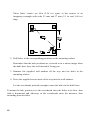
1
DFE-904 Ethernet/Fast Ethernet Dual-Speed Hub User’s Guide Rev. 01 (November 1997) 6DFE904...01 Printed In Taiwan RECYCLABLE Trademarks Copyright 1997 by D-Link Corporation. Contents subject to change without prior notice. D-Link is a registered trademark of D-Link Corporation and D-Link Systems, Inc. All other trademarks belong to their respective owners. Copyright Statement No part of this publication may be reproduced in any form or by any means or used to make any derivative such as translation, transformation, or adaptation without permission from D-Link Corporation or D-Link Systems Inc., as stipulated by the United States Copyright Act of 1976. FCC Warning This equipment has been tested and found to comply with the limits for a Class A digital device, pursuant to Part 15 of the FCC Rules. These limits are designed to provide reasonable protection against harmful interference when the equipment is operated in a commercial environment. This equipment generates, uses, and can radiate radio frequency energy and, if not installed and used in accordance with this guide, may cause harmful interference to radio communications. Operation of this equipment in a residential area is likely to cause harmful interference, in which case the user will be required to correct the interference at his or her own expense. CE Mark Warning This is a Class A product. In a domestic environment, this product may cause radio interference, in which case the user may be required to take adequate measures. Limited Warranty Hardware: D-Link warrants its hardware products to be free from defects in workmanship and materials, under normal use and service, for the following lengths of time from the date of purchase from D-Link or its Authorized Reseller: Product Type Network adapters Unmanaged and managed hubs (10 Mbps) Unmanaged hubs (100 Mbps) Managed hubs (100 Mbps) Unmanaged and managed dual-speed hubs (10/100 Mbps) * Power supply and fans in these devices Other hardware products Spare parts and spare kits Period Lifetime Lifetime * Lifetime * One year One year One year One year 90 days If a product does not operate as warranted during the applicable warranty period, D-Link shall, at its option and expense, (1) repair the defective product or part, (2) deliver to Customer an equivalent product or part to replace the defective item. All products that are replaced will become the property of D-Link. Replacement products may be new or reconditioned. Any replaced or repaired product or part has a ninety (90) day warranty or the remainder of the initial warranty period, whichever is longer. D-Link shall not be responsible for any software, firmware, information, or memory data of Customer contained in, stored on, or integrated with any products returned to D-Link pursuant to any warranty. All products with lifetime warranty have a standard five-year warranty. To qualify for lifetime warranty, the enclosed Product Registration Card must be completed and returned to D-Link within ninety (90) days of purchase. Warranty service may be obtained by contacting a D-Link office within the applicable warranty period for a Return Material Authorization (RMA) number. If a Registration Card has not been previously sent, proof of purchase, such as a copy of the dated purchase invoice, must be provided. Once an RMA number is issued, the defective product must be shipped back to D-Link prepaid, insured and wrapped in the original or similar shipping package to ensure that it will not be damaged during shipment. When returning the defective product to D-Link for service, the RMA number must be marked on the outside of the shipping package. Any product returned without an RMA number shall be rejected and sent back to the Customer, and D-Link reserves the right to have Customer bear the cost of sending back such products. A service charge may or may not be levied to Customer by D-Link. To find out if a service charge is levied or not, and the charged amount, read the RMA that is returned to Customer, or ask the DLink office when an RMA is requested. EXCLUSIVE REMEDY IF THE D-LINK PRODUCT DOES NOT OPERATE AS WARRANTED ABOVE, THE CUSTOMER'S SOLE REMEDY SHALL BE, AT D-LINK'S OPTION, REPAIR OR REPLACEMENT. THE FOREGOING WARRANTIES AND REMEDIES ARE EXCLUSIVE AND ARE IN LIEU OF ALL OTHER WARRANTIES, EXPRESSED OR IMPLIED, EITHER IN FACT OR BY OPERATION OF LAW, STATUTORY OR OTHERWISE, INCLUDING WARRANTIES OF MERCHANTABILITY AND FITNESS FOR A PARTICULAR PURPOSE. D-LINK NEITHER ASSUMES NOR AUTHORIZES ANY OTHER PERSON TO ASSUME FOR IT ANY OTHER LIABILITY IN CONNECTION WITH THE SALE, INSTALLATION MAINTENANCE OR USE OF D-LINK'S PRODUCTS D-LINK SHALL NOT BE LIABLE UNDER THIS WARRANTY IF ITS TESTING AND EXAMINATION DISCLOSE THAT THE ALLEGED DEFECT IN THE PRODUCT DOES NOT EXIST OR WAS CAUSED BY THE CUSTOMER'S OR ANY THIRD PERSON'S MISUSE, NEGLECT, IMPROPER INSTALLATION OR TESTING, UNAUTHORIZED ATTEMPTS TO REPAIR, OR ANY OTHER CAUSE BEYOND THE RANGE OF THE INTENDED USE, OR BY ACCIDENT, FIRE, LIGHTNING OR OTHER HAZARD. LIMITATION OF LIABILITY IN NO EVENT WILL D-LINK BE LIABLE FOR ANY DAMAGES, INCLUDING LOSS OF DATA, LOSS OF PROFITS, COST OF COVER OR OTHER INCIDENTAL, CONSEQUENTIAL OR INDIRECT DAMAGES ARISING OUT THE INSTALLATION, MAINTENANCE, USE, PERFORMANCE, FAILURE OR INTERRUPTION OF A D- LINK PRODUCT, HOWEVER CAUSED AND ON ANY THEORY OF LIABILITY. THIS LIMITATION WILL APPLY EVEN IF D-LINK HAS BEEN ADVISED OF THE POSSIBILITY OF SUCH DAMAGE. IF YOU PURCHASED A D-LINK PRODUCT IN THE UNITED STATES, SOME STATES DO NOT ALLOW THE LIMITATION OR EXCLUSION OF LIABILITY FOR INCIDENTAL OR CONSEQUENTIAL DAMAGES, SO THE ABOVE LIMITATION MAY NOT APPLY TO YOU. CONTENTS Introduction..................................................................................... 1 Product Description......................................................................... 1 Unpacking and Setup ...................................................................... 3 Identifying External Components.................................................... 4 Front Panel .............................................................................................. 4 Side Panels .............................................................................................. 6 Back Panel............................................................................................... 7 Installing the Hub ........................................................................... 9 Single-hub Network ................................................................................. 9 Multi-hub Ethernet Network ...................................................................11 Two-hub Fast Ethernet Network..............................................................13 Mounting....................................................................................... 14 Horizontal Mounting...............................................................................15 Vertical Mounting...................................................................................15 Powering Up.................................................................................. 17 Specifications ................................................................................ 18 Introduction This guide explains how to set up and use the D-Link DFE-904 Ethernet/Fast Ethernet mini-hub. The DFE-904 is a sophisticated device that must be installed and operated as described in this guide to work correctly. Follow the instructions in this guide carefully to ensure that your DFE-904 will provide many years of trouble-free operation. The D-Link DFE-904 dual-speed Ethernet/Fast Ethernet hub is designed to allow easy migration and integration between 10-Mbps Ethernet and 100-Mbps Fast Ethernet. The DFE-904 hub can operate with either IEEE 802.3 10BASE-T connections (twisted-pair Ethernet operating at 10 megabits per second), or IEEE 802.3u 100BASE-TX connections (twisted-pair Fast Ethernet operating at 100 megabits per second). Product Description The DFE-904 is two hubs in one: an Ethernet hub that works at 10 megabits per second (Mbps), and a Fast Ethernet hub that works at 100 Mbps. Important: The DFE-904 can work at 10 or 100 Mbps, but not at both speeds at the same time. The devices that you connect to the DFE-904 must all access the network at the same speed. 1 Standards for 10-Mbps Ethernet and 100-Mbps Fast Ethernet are administered by the International Institute of Electrical and Electronics Engineers (IEEE). The DFE-904 conforms fully to IEEE standards for hubs of its type. As a 10-Mbps Ethernet hub, the DFE-904 conforms to the IEEE's 10BASE-T standard. 10BASE-T stands for 10-Mbps "baseband" (that is, one-bit-at-a-time) signaling on twisted-pair cables. Technical note: Twisted-pair cables contain wires wound together in pairs to reduce electromagnetic interference (EMI). Some also have foil shielding to further reduce EMI. As a 100-Mbps Fast Ethernet hub, the DFE-904 conforms to the 100BASE-TX Class II standard. Terminology tip: The X in 100BASE-TX means that signals cross from the sender's transmit lines to the receiver's receive lines (this crossover occurs within the hub). 10BASE-T has crossover also, but no X; the X was added to distinguish 100BASE-TX from 100BASE-T4, a Fast Ethernet standard with no crossover. 100BASE-TX Class II hubs can be connected to each other using twisted-pair cabling; Class I hubs cannot. A twisted-pair connection between hubs is called an uplink. Terminology Tip: In an uplink connection, neither side is really "higher" than the other; uplinking simply lets each side pass to the other all valid signals that it receives from networked devices. Uplinking is sometimes referred to as cascading or daisychaining. Both 10BASE-T and 100BASE-TX allow uplinking, but the two standards have very different rules for uplink connections. Follow the connection instructions in this guide very carefully. 2 When used as a 10BASE-T Ethernet hub, the DFE-904 can interconnect end nodes and other 10BASE-T hubs in many different combinations, as long as the connection rules given in this guide are followed. Most often, the hub is used either (a) to interconnect four end nodes, or (b) to interconnect three end nodes and another hub. This guide covers both these and other ways to use the hub on a 10BASE-T network. Terminology tip: An end node is a device that can originate signals and be addressed by other devices on a network. Servers, singleuser computers, bridges, routers, and switching hubs are end nodes; hubs such as the DFE-904 are not. The DFE-904 is the type of hub technically known as a multi-port repeater or repeating hub. Unless preceded by the word switching, the word hub in this guide always refers to a repeating hub. When used as a 100BASE-TX Fast Ethernet hub, the DFE-904 can interconnect either (a) four end nodes, or (b) three end nodes and another hub. These are the only connection methods allowed by the 100BASE-TX standard for hubs such as the DFE-904. This guide covers both methods in detail. It is assumed in this guide that you will first use the DFE-904 as a 10BASE-T Ethernet hub and later convert your network to 100BASE-TX Fast Ethernet. The requirements for each type of network are explained in detail in the relevant sections of this guide. Unpacking and Setup This chapter provides information on the unpacking and initial installation of your hub. 3 Open the shipping carton of your hub and carefully unpack the contents. The carton should contain the following items: ♦ One dual-speed hub ♦ One AC power adapter, suitable for your area electrical power connections ♦ Mounting accessories (rubber feet, screws, and wall anchors) ♦ This User’s Guide Inspect the hub and all accompanying items. If any item is damaged or missing, report the problem immediately to your computer equipment dealer. Identifying External Components This section identifies all the major external components of the hub. Both the front and rear panels are shown, followed by a description of each panel feature. The indicator panel is described in detail in the next chapter. Front Panel On the DFE-904's front panel are the hub's Speed, Link/Rx, and Collision indicators. The Speed and Link/Rx indicators are all green light-emitting diodes (LEDs); the Collision indicator is a yellow LED. 4 The Speed indicators are labeled 100 and 10. These indicators show whether the hub is set for 100-Mbps or 10-Mbps operation. Hub speed is set using a sidepanel switch described in the next section. The Speed indicators also serve as power indicators. One or the other should shine whenever the hub has power. If neither one lights up when power is applied, contact the dealer for service. The Link/Rx indicators are numbered from 1 to 4. Each shows the current status of one of the hub's four ports. - When the hub detects a good connection to a device and the device is not transmitting, the Link/Rx indicator for the port shines a steady green to show "link OK" (note that the device must be turned on for the connection to be detected). - When the hub detects a transmission from a correctly operating device, the Link/Rx indicator for the port blinks off and on to show "receiving" (Rx). Technical Note: A Link/Rx indicator blinks only when signals come in on a port, not when signals go out. Valid signals received on one port are immediately sent out on all other ports. The Link/Rx indicators are important for troubleshooting. When the hub and a connected device both have power and the Link/Rx indicator for the port is unlit, the reason might be a faulty cable or adapter, a loose connection, or partitioning of the port (see next). The Collision indicator flashes yellow whenever two devices on the network attempt to transmit at the same time. Occasional collisions are normal in both 5 Ethernet and Fast Ethernet. If collisions become very frequent, the cause might be faulty cabling, network overload, or a malfunctioning device. Important: If too many consecutive transmissions from a device result in collisions, the hub will partition the port the device is connected to — that is, it will block transmissions coming in on that port. When a port is partitioned, its Link/Rx indicator does not light up. The hub will automatically departition the port when it detects that the connected device is operating correctly. Partitioning prevents a malfunctioning device from disrupting the network. Automatic partitioning and departitioning are required features of Ethernet and Fast Ethernet hubs. The term collision domain is often used to describe an Ethernet or Fast Ethernet network. A collision domain is a collection of end nodes whose signals can collide. End nodes connected to the same hub or to uplinked hubs are in the same collision domain; end nodes linked through a bridge, router, or switching hub are in separate collision domains. In this manual, the word network always refers to a collision domain. Side Panels On the DFE-904's right-hand panel are the speed switch and air inlets. The lefthand panel holds the fan outlet. 6 The speed switch is marked 100 M (for 100-Mbps Fast Ethernet) at one end and 10 (for 10-Mbps Ethernet) at the other. To prevent accidental changing of the setting, the switch tab protrudes only slightly. A groove in the tab lets you set the switch with a fingernail or pencil tip. Slide the tab toward the front of the hub for 100-Mbps operation and toward the back for 10-Mbps operation. The setting can be adjusted at any time, whether the hub is on or off. The air inlets on the right side and the fan outlet on the left side allow the cooling fan to maintain airflow in the hub. Important: Never block the air inlets or the fan outlet. Cooling is extremely important for the hub. Back Panel On the back of the hub, starting at the end closest to the fan, are the hub's DC power jack and five RJ-45 jacks labeled 1, 2, 3, 4, and Uplink. The DC power jack is marked with the voltage, amperage, and polarity required by the hub (9V DC, 1A, inside positive, outside negative). This jack takes a barrel connector such as that on the supplied AC adapter. Use only this adapter or an equivalent adapter obtained from your computer equipment dealer. You can connect the hub to DC power at any time. The Collision indicator and the indicator for the currently selected speed will light up. After a few seconds the Collision indicator will go out and the hub will be ready. 7 Jacks 1, 2, 3, and 4 are RJ-45 connectors for the hub's network ports. Each is wired to work with a cable from a network end node or from another hub's uplink jack. The Uplink jack is an RJ-45 jack wired for an uplink connection to another hub. This jack is part of the same circuit as jack 4; never use both of these jacks at the same time. Technical Note: The difference between the Uplink jack and jack 4 is that the transmit and receive lines are crossed in jack 4 and uncrossed in the Uplink jack. If the hub had no Uplink jack, you would need a special cross-wired cable to make an uplink connection. Use the Uplink jack only for a connection to another hub, never for a connection to an end node. Note that such a connection will require a cross-wired jack (the kind that is wired for an end node) on the other hub. Use only standard (straight-through) UTP or STP cables with the DFE-904. Category 3, 4, and 5 cables are all acceptable for 10 Mbps; only Category 5 and equivalent cables are acceptable for 100 Mbps. Network cables can be attached and detached at any time, whether the hub is on or off. Read the relevant connection instructions in this guide carefully before making connections. Bottom Panel On the bottom of the hub are two mounting holes and four indented square outlines. The mounting holes, together with the supplied screws and wall anchors, let you mount the hub on a vertical surface. The holes are diagonally oriented so the hub can face in any direction. We recommend mounting the hub with its cable jacks facing down or sideways to help keep dust off the contacts. 8 The square outlines show where to attach the rubber feet included with the hub. The feet help to cushion the hub, and should be attached whether you set the hub on a desk, table, etc., or mount it on a vertical surface. Installing the Hub When you connect only end nodes to the DFE-904, connections are made the same way whether the network works at 10 Mbps or 100 Mbps. The first section of this chapter explains how to make connections for a one-hub network. The second section of this chapter explains how to make connections for a multihub network that runs at 10 Mbps. If your network runs at 100 Mbps and you wish to connect another 100BASE-TX Class II hub to the DFE-904, see the third section of this chapter. Caution: A twisted-pair network cable can ordinarily be connected or disconnected at any time, whether the devices are on or off. Where an end node has a plug-in adapter, however, we strongly recommend turning the end node off before connecting it for the first time. If the plug fits poorly and the adapter is loose, forcible insertion can momentarily open an internal contact and damage both the adapter and the end node. Single-hub Network If your network consists of the DFE-904 and two, three, or four end nodes only, make connections as described in this section. 9 For the purpose of making connections to the DFE-904, a bridge, router, or switching hub (also known as a "switch") is considered an end node. Such a device acts as an end node in each of two or more collision domains, making them seem like a single network. Before making connections, check the rules and precautions and the mounting instructions given in this guide. Make sure all requirements for safe, correct operation have been met. Make connections for each end node as follows: 1. Double-check to make sure the end node will access the network at the same speed as the hub and your other end nodes (10 or 100 Mbps). Check the setting of the DFE-904's speed switch and the specifications for the end node's network interface. 2. Select a cross-wired RJ-45 jack on the hub. This can be any one of the jacks labeled 1 through 4. 3. Plug one end of the cable into the end node's RJ-45 jack. Align the plug so its contacts will meet the metal contacts inside the jack, then push it in firmly. The plug's catch tab should click audibly when the plug is all the way in. 4. Plug the cable's other end into the selected jack on the hub. The following figure shows a single-hub network on which all possible connections to the DFE-904 have been made. 10 Multi-hub Ethernet Network If all your end nodes will access the network at 10 Mbps and you will connect the DFE-904 to one or more other hubs, make connections as described in this section. Before making connections, check the rules and precautions and the mounting instructions given in this guide. Make sure all requirements for safe, correct operation have been met. Important: This section describes how to create a multi-hub 10-Mbps network in which all the hubs are DFE-904 units. If you have 10BASE-T hubs of other kinds as well, see those hub's manuals for instructions on making end node and uplink connections. All 10BASE-T hubs allow uplinking. On some, however, you must set a switch to make a jack suitable for uplinking, and on some the jack used for uplinking is labeled not Uplink but MDI-II (medium-dependent interface, uncrossed). Interconnecting Two 10BASE-T Hubs With two DFE-904 units working at 10 Mbps uplinked together, you can create a network that will accommodate up to six end nodes. Interconnect the hubs as follows: 1. For the sake of identification, designate one hub as hub A and the other as hub B. 11 2. Set both hubs for 10 Mbps. 3. Make sure jack 4 on hub A is unused. This jack must remain unused after all connections are made. 4. Plug one end of a suitable cable into hub A's Uplink jack. Use the same kind of cable as you would use for a 10BASE-T end node. 5. Plug the other end of the cable into any jack except the Uplink jack on hub B. Assuming you are interconnecting only two hubs, you can use all of hub B's numbered jacks, but you must leave hub B's Uplink jack unused. Connect end nodes to the hubs as described under "Single-hub Network," above, but leave jack 4 on hub A and the Uplink jack on hub B unused. The following figure shows a two-hub 10-Mbps network on which all possible connections to both hubs have been made. Connecting Additional Hubs To add a third and a fourth hub to a 10-Mbps network, connect them between hubs A and B. The four hubs on the left in the figure below show how connections should be made. Once you have interconnected four 10-Mbps hubs, any additional hubs must be uplinked to the two middle hubs, as shown below. This ensures that there 12 will be no more than three uplink connections between any two end nodes. The following illustration shows a maximum-extent 10-Mbps network created with DFE-904 units. Two-hub Fast Ethernet Network When set for 100-Mbps operation, the DFE-904 can have a single uplink connection to another 100BASE-TX Class II Fast Ethernet hub. In addition to the 100-meter (328-foot) absolute limit on the length of any single cable, there must not be more than 205 meters (672.4 feet) of cabling between any two end nodes. This is shown in the following illustration. 13 Mounting You can mount the DFE-904 on a desk, table, or other firm horizontal surface, or on a vertical surface such as a wall or the side of a desk. Important: Choose a location where the air inlets and fan outlet will never be blocked. Make sure the hub will not be exposed to direct sunlight, strong magnetic fields, excessive moisture, very dusty air, extreme heat or cold, or rapid temperature changes. Before mounting the hub, check the distance from the planned location to each device you will connect to the hub. Make sure all connections can be made using cables of allowable lengths: - On a 10-Mbps Ethernet network, every cable can be up to 100 meters (328 feet) long. If hubs are uplinked together, there can be no more than three uplink connections between any two end nodes. - On a 100-Mbps Fast Ethernet network with no uplink connection (that is, just the DFE-904 and four end nodes), every cable can be up to 100 meters (328 feet) long. This allows a maximum signal path of 200 meters (656 feet). - On a 100-Mbps Fast Ethernet network with an uplink connection (for example, two DFE-904 units uplinked together and six end nodes), no cable 14 can be more than 100 meters (328 feet) long, and the signal path between any two end nodes must not exceed 205 meters (672.4 feet). If both hubs have end nodes connected through 100-meter-long cables, the uplink cable cannot be more than 5 meters (16.4 feet) long. Horizontal Mounting Prepare the hub for desktop or tabletop mounting as follows: 1. Make sure the hub's bottom surface is clean. 2. Peel the backing from the supplied rubber feet. 3. Attach the feet to the hub's bottom surface, one in each corner. Then set the hub in place and make sure it will not easily rock or slide. Also make sure nothing will press against the air inlets or the fan outlet. Vertical Mounting To mount the hub on a vertical surface you will need a medium-size Phillips screwdriver. You might also need a drill, a drill bit suitable for the supplied wall anchors, and a hammer. We strongly recommend mounting the hub with its cable jacks facing down or sideways to help keep dust off the contacts. If the surface does not already have suitable mounting holes, prepare it as follows: 1. Note the arrangement of the mounting holes in the hub's base. 15 These holes' centers are 65m (2.56 in.) apart, at the corners of an imaginary rectangle with sides 53 mm and 37 mm (2.1 in. and 1.46 in.) long. 2. Drill holes in the corresponding positions on the mounting surface. Remember that the hole positions are reversed as in a mirror image when the hub's base faces the wall instead of facing you. 3. Hammer the supplied wall anchors all the way into the holes in the mounting surface. 4. Drive the supplied screws most of the way into the wall anchors. Let the screwheads protrude enough to enter the holes in the hub's base. To mount the hub, position it so the screwheads enter the holes in its base, then slide it downward and sideways so the screwheads enter the narrower slots extending from the holes. 16 Powering Up The DFE-904 and connected devices can be powered up in any order. Before powering up the DFE-904, make sure that — - the hub is set to work at the speed at which all connected devices will access the network; - the AC adapter is designed for the line voltage and the kind of AC outlet used in your location; - the adapter provides the voltage, amperage, and polarity required by the hub (9V DC, 1A, inside positive, outside negative) and has the correct type of barrel connector for the hub's DC power jack. Important: Double-check the input rating of the supplied power adapter to make sure it matches the line voltage in your area. If it does not, contact your computer equipment dealer and obtain a replacement adapter. When certain that the power adapter is suitable, plug the adapter into a standard wall outlet and plug the adapter's barrel connector into the DFE-904's DC power jack. When power is applied, the Collision indicator and the indicator for the currently selected speed will light up. After a few seconds the Collision indicator will go out and the hub will be ready. 17 Specifications Standards: IEEE 802.3 10BASE-T Ethernet repeater, IEEE 802.3u 100BASE-TX Fast Ethernet repeater (Class II). Topology: Star. Protocol: CSMA/CD. Data Transfer Rate: Ethernet—10 Mbps; Fast Ethernet—100 Mbps. Number of Ports: Four. Network Media: Ethernet—Category 3 or better UTP or STP cable; max. cable length 100 m, max. cabling between stations 500 m. Fast Ethernet—Category 5 or better UTP or STP cable; max. cable length 100 m, max. cabling between stations 205 m. Indicators: 10 Mbps, 100 Mbps, collision, port link/activity. Power Supply: External power supply with 9V DC/1A output. Power Consumption: 4W. Dimensions (W × D × H): 110 × 75 × 29 mm (4.33 × 2.95 × 1.14 in.) Weight: 500 g. Operating Temperature: -10° to 55° C. Storage Temperature: -25° to 55° C. Humidity: 5% to 95%, non-condensing. Cooling: One 25 × 25 × 10 mm DC fan. Emissions: FCC Class A, CE , VCCI Class A, C-Tick. Safety: UL, CSA. 18