1
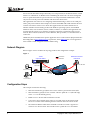
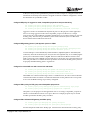
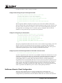
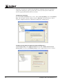
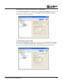
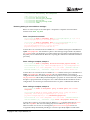
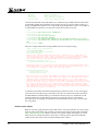
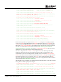
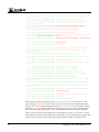
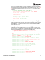
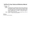
Application Note
J Series / SRX Series
Remote Access VPN with XAuth
Configuration and Troubleshooting
Version 1.5
Richard Kim
Technical Support Engineer
Advanced JTAC
June 2009
Juniper Networks, Inc.
1194 North Mathilda Avenue
Sunnyvale, CA 94089 USA
408 745 2000 or 888 JUNIPER
www.juniper.net
Contents
Introduction ........................................................................................................................................... 3
Included Platforms and Software Versions ....................................................................................... 3
Overview ................................................................................................................................................ 3
Network Diagram ................................................................................................................................. 4
Configuration Steps .............................................................................................................................. 4
Basic Steps to Configure .................................................................................................................... 5
Corporate Office Configuration Example .......................................................................................... 5
Configure interface IP addresses...................................................................................................... 5
Configure default route ..................................................................................................................... 6
Configure security zones and assign interfaces to the zones ....................................................... 6
Configure host-inbound services for each zone ............................................................................. 6
Configure address book entry for “trust” zone.............................................................................. 6
Configure access profile for XAuth users........................................................................................ 6
Configure IKE policy for aggressive mode, Compatible proposal-set and pre-shared key ..... 7
Configure IKE gateway (phase 1) with dynamic peer as u-FQDN ............................................. 7
Configure for shared IKE user with 10 user limit and XAuth...................................................... 7
Configure IPSec policy for PFS group 2 and Compatible proposal set....................................... 7
Configure IPSec VPN with IKE gateway and IPSec policy .......................................................... 7
Configure VPN security policy for incoming tunnel traffic ......................................................... 8
Configure security policy for Internet traffic.................................................................................. 8
Configure tcp-mss to eliminate fragmentation of TCP traffic across the tunnel ....................... 8
NetScreen-Remote Client Configuration............................................................................................ 8
Verifying Configuration ..................................................................................................................... 12
Confirm IKE (phase 1) status .......................................................................................................... 12
Confirm XAuth status...................................................................................................................... 12
Confirm IPsec (phase 2) status........................................................................................................ 13
Check statistics and errors for an IPSec SA................................................................................... 14
Test traffic flow across the VPN ..................................................................................................... 14
Troubleshooting Basics ....................................................................................................................... 15
Checking traceoption logs............................................................................................................... 15
Troubleshooting IKE and IPSec Issues ............................................................................................. 16
Enable IKE traceoptions for phase 1 and phase 2 negotiation issues ........................................ 16
Reviewing kmd log for success/failure messages ........................................................................ 17
Troubleshooting Authentication (XAuth) Issues ............................................................................ 19
Enable authentication traceoptions for XAuth issues.................................................................. 19
Troubleshooting Flow Issues ............................................................................................................. 20
Problem Scenario.............................................................................................................................. 20
Enable security flow traceoptions for routing or policy issues .................................................. 21
Reviewing trace outputs.................................................................................................................. 22
Appendix A: Show Configuration .................................................................................................... 26
2
Copyright © 2007, Juniper Networks, Inc.
Introduction
Building upon the existing JUNOS key management daemon, JUNOS has integrated valueadded features from ScreenOS. This approach combines the best of both worlds, providing a
robust and advanced IKE implementation. The purpose of this application note is to detail
IPSec interoperability configuration between a J Series or SRX Series device and a remote access
(formerly referred to as dialup) peer. In this example we will be using Juniper Networks
NetScreen-Remote VPN Client which is a robust IPSec client application for Windows-based
systems. This application note also includes troubleshooting information for J Series and SRX
Series devices, as well as some basic details from NetScreen-Remote VPN Client.
Included Platforms and Software Versions
This document applies to the following devices:
•
•
J Series devices running:
o
JUNOS 9.4 and above
o
JUNOS with Enhanced Services 8.5 through 9.3
SRX210, SRX240, and SRX650 (Check KB14370 for the latest list of supported devices.)
Overview
Before discussing configuration of a remote access VPN, it is important to understand the
difference when compared with a site-to-site VPN. A site-to-site VPN consists of two VPN peer
endpoints which service network(s) on both sides. PC clients do not need to run any particular
VPN application and need only to point to the VPN device as the gateway to reach the remote
network. This requires two devices on each end with the ability to terminate the VPN tunnel
and also route traffic to the network(s) they service. In a remote access VPN, on one side there is
no tunnel gateway endpoint device; the tunnel extends directly to the client itself. Thus the
tunnel endpoint on the remote access peer services only that host and does not service a
network. For this reason a policy-based VPN tunnel makes sense. While you can configure
route-based for dialup VPN peers, this is not common and not considered ideal for this
scenario. In addition, since the client tunnel peer is not identified by IP address this allows for
consolidation of multiple clients sharing a single IKE gateway configuration. This can be done
with either group IKE or shared IKE.
Group IKE with pre-shared keys is a technique for performing IKE authentication for a group
of dialup users with out configuring separate IKE profiles for each one. The VPN gateway uses
a single group IKE profile which contains the partial IKE ID. A dialup user can successfully
build a VPN tunnel to a gateway if the VPN client has the correct pre-shared key and if the
rightmost part of the userʹs full IKE ID matches the group IKE ID. However the security risk is
such that an unauthorized client with the correct pre-shared key and group ID could establish a
VPN without restriction. Thus if the group ID and pre-shared keys were compromised then this
would require that the J Series or SRX Series device and all clients be updated with the new
group ID and pre-shared key.
Shared IKE also facilitates the deployment of a large number of remote access users. The VPN
gateway authenticates multiple remote access users using a single shared IKE ID and preshared key. However shared IKE differs from group IKE in that extended authentication
(XAuth) is mandatory which adds another layer of authentication to the VPN client. This means
Copyright © 2007, Juniper Networks, Inc.
3
that even if the shared ID and pre-shared key were compromised, an unauthorized user would
still have to authenticate via Radius before establishing the VPN. This is far more manageable
since if a particular XAuth user password were to be compromised the administrator would
only need to reset the password on Radius and inform the affected user.
This application note will focus on configuring and troubleshooting a remote access VPN peer
with a policy-based VPN. In this example we will use shared IKE and XAuth which is the most
common scenario for remote access clients. This application note assumes that the user is
familiar with the basic functioning of Microsoft Windows operating systems, and standard
Windows items, such as buttons, menus, toolbars, windows, etc. Further, this application note
assumes that the remote access client has an Internet connection, whether through a private
network, DSL connection, Ethernet, wireless Ethernet, dial-up modem, or some other form of
connection.
Additional J Series and SRX Series specific application notes can be found on Juniper Networks’
Knowledge Base at http://kb.juniper.net. In particular, article KB10182 lists several application
notes related to VPN configuration and troubleshooting.
Network Diagram
Refer to Figure 1 below for Network Topology used for this configuration example.
Figure 1.
Clear traffic
VPN traffic
J4350
Corporate Office
ER
POW
US
0
STAT
1
M
ALAR
HA
POWER
RESET
CONFIG
TX/RX
0/0
L INK T X/RX
0/ 1 LIN K TX/RX 0/2
10/1 00/10 00
L INK T X/R X
0/3
LI NK
CO NSO LE
AUX
SLOT NUMBER
1
2
3
4
5
6
J635 0
US B
ge-0/0/0.0
10.10.10.1/24
zone: trust
Radius
10.10.10.100/24
NetScreen-Remote
VPN Client
192.168.168.10/24
ge-0/0/3.0
1.1.1.2/30
zone: untrust
edge router
1.1.1.1/30
NAT router
5.5.5.5
Host
10.10.10.10/24
Configuration Steps
This example assumes the following:
4
•
Internal LAN interface ge-0/0/0 in zone “trust” will have private IP 10.10.10.10/24.
•
Internet interface ge-0/0/3 in zone “untrust” will have public IP 1.1.1.2/30 with edge
router 1.1.1.1 as the default gateway.
•
Radius server is 10.10.10.100 on internal local LAN.
•
You want to allow all traffic from remote access VPN clients to the internal LAN.
However no traffic will be initiating from the internal LAN to the remote clients.
•
The NetScreen-Remote VPN Client is behind a NAT device which is typical for a
remote access client scenario. The NAT device has a public IP 5.5.5.5 and will be
Copyright © 2007, Juniper Networks, Inc.
performing port translation for the 192.168.168.0/24 private subnet.
•
NetScreen-Remote VPN Client is already installed and working properly on a
Windows-based PC.
Basic Steps to Configure
1.
Configure the IP addresses for ge-0/0/0.0 and ge-0/0/3.0.
2.
Configure default route to Internet next-hop. Optionally you can use a dynamic routing
protocol such as OSPF instead but that is beyond the scope of this app note.
3.
Configure security zones and bind the interfaces to the appropriate zones. Also be sure to
enable necessary host-inbound services on the interfaces or the zone. For this example
you must enable IKE service on either ge-0/0/3 interface or the untrust zone.
4.
Configure address book entries for the internal LAN subnet in the trust zone. This will be
needed for the tunnel policy and must match the Remote Party subnet in NetScreenRemote.
5.
Configure access profile to specify Radius server parameters. It may also be desirable to
configure an idle timeout to drop the tunnel if there is no activity for a certain period of
time.
6.
Configure phase 1 (IKE) gateway settings for aggressive mode and dynamic IP peer. For
this example we are using “Compatible” proposal set. However you can create a
different proposal based on your corporate security policy.
7.
Configure shared IKE user type with user limit. For this example we will allow up to 10
users. Also configure XAuth to use the access profile as configured in step 5.
8.
Configure phase 2 (IPSec) VPN settings. For this example we are using “Compatible”
proposal set and PFS group 2. However you can create a different proposal based on
your corporate security policy.
9.
Configure VPN security policies to permit VPN client traffic into the corporate LAN.
Note that for JUNOS-ES 8.5, bidirectional policies are not supported. Also configure
outgoing trust to untrust permit all policy with source NAT for Internet traffic.
10.
Configure tcp-mss for IPSec traffic to eliminate the possibility of fragmented TCP traffic.
This can decrease the resource utilization on the device.
Corporate Office Configuration Example
To begin, enter configuration mode with either command: configure or edit.
Configure interface IP addresses
set interfaces ge-0/0/0 unit 0 family inet address 10.10.10.1/24
set interfaces ge-0/0/3 unit 0 family inet address 1.1.1.2/30
JUNOS uses the concept of units for the logical component of an interface. In this example unit
0 and family inet (IPv4) is used.
Configure default route
Copyright © 2007, Juniper Networks, Inc.
5
set routing-options static route 0.0.0.0/0 next-hop 1.1.1.1
This is the only required static route for this example. Note that no route is required for
incoming direction.
Configure security zones and assign interfaces to the zones
set security zones security-zone trust interfaces ge-0/0/0.0
set security zones security-zone untrust interfaces ge-0/0/3.0
The ingress and egress zones are determined by the ingress and egress interfaces involved in
the route lookup. Thus from above we can see that IPSec packets incoming on ge-0/0/3 also
means that the ingress zone is “untrust”. Following the route lookup we can see the egress
interface for 10.10.10.0/24 subnet is ge-0/0/0 thus the egress is zone “trust”. So the tunnel policy
will need to be “from-zone untrust to-zone trust”.
Configure host-inbound services for each zone
set security zones security-zone trust host-inbound-traffic system-services all
set security zones security-zone untrust host-inbound-traffic system-services ike
Host-inbound services are for traffic destined for the J Series or SRX Series device itself. This
includes but is not limited to FTP, HTTP, HTTPS, IKE, ping, rlogin, RSH, SNMP, SSH, Telnet,
TFTP and traceroute. For this example we are assuming that we want to allow all such services
from zone “trust”. For security reasons we are only allowing IKE on the Internet facing zone
“untrust” which is required for IKE negotiations to occur. However other services such as for
management and/or troubleshooting can also be individually enabled if required.
Configure address book entry for “trust” zone
set security zones security-zone trust address-book address local-net
10.10.10.0/24
For this example we are using address-book object name “local-net” to represent 10.10.10.0/24.
This address must match the remote party subnet configured in NetScreen-Remote. This
address will be used for the proxy-id during phase 2 negotiations. There are some limitations
with regards to which characters are supported for address-book names. Please refer to
complete JUNOS documentation for more details.
Configure access profile for XAuth users
set access profile xauth-users authentication-order radius
set access profile xauth-users session-options client-idle-timeout 180
set access profile xauth-users radius-server 10.10.10.100 port 1812
set access profile xauth-users radius-server 10.10.10.100 secret “radius"
Radius authentication is mandatory for shared IKE user type. Thus an access profile must
specify Radius in the authentication order. The J Series or SRX Series device will be a network
access server (NAS) and needs to be configured as a client on the Radius server. The necessary
components to configure a client in Radius include a NAS IP and Radius secret. By default the
NAS IP is the IP of the egress interface of the Radius request packet on the J Series or SRX Series
device, but the NAS IP can also be manually configured to any other IP that is owned by the J
Series or SRX Series device. Other details which may be included are the Radius port (typically
1812 or 1645) and client idle timeout. The client idle timeout will drop the SA if the connection
6
Copyright © 2007, Juniper Networks, Inc.
is idle (no activity) for the specified time period. So for this example we configured a timeout of
180 minutes of inactivity before the SA is dropped. For details on Radius configuration, consult
documentation for your Radius vendor.
Configure IKE policy for aggressive mode, Compatible proposal-set and pre-shared key
set security ike policy dialup-policy1 mode aggressive
set security ike policy dialup-policy1 proposal-set compatible
set security ike policy dialup-policy1 pre-shared-key ascii-text "secretkey"
Aggressive mode is recommended for dynamic IP peers. For the purposes of this application
note we are using aggressive mode and “Compatible” proposal set. However, a unique
proposal may be created and then specified in the IKE policy in accordance with your corporate
security policy. Note that the pre-shared key must match on both the J Series or SRX Series
device and the NetScreen-Remote VPN client.
Configure IKE gateway (phase 1) with dynamic peer as u-FQDN
set security ike gateway dialup-ike ike-policy dialup-policy1
set security ike gateway dialup-ike dynamic user-at-hostname “[email protected]”
set security ike gateway dialup-ike external-interface ge-0/0/3
A remote IKE peer can be identified by either IP address, FQDN/u-FQDN or ASN1-DN (PKI
certificates). Since the client IP may not always be the same (dynamic IP), we are identifying the
peer by user-at-hostname which is u-FQDN. Therefore all NetScreen-Remote clients would
need to specify the same u-FQDN. It is important also to specify the correct external interface. If
either the peer address or external interface specified is incorrect then the IKE gateway will not
be properly identified during phase 1 negotiations.
Configure for shared IKE user with 10 user limit and XAuth
set security ike gateway dialup-ike dynamic ike-user-type shared-ike-id
set security ike gateway dialup-ike dynamic connections-limit 10
set security ike gateway dialup-ike xauth access-profile xauth-users
Shared IKE user connection limit range is from 1 to 1000. However, be sure to observe the limit
on maximum number of tunnels as stated in the datasheets for the platform. The access profile
is set to use the Radius settings as previously configured.
Configure IPSec policy for PFS group 2 and Compatible proposal set
set security ipsec policy dialup-policy2 perfect-forward-secrecy keys group2
set security ipsec policy dialup-policy2 proposal-set compatible
Like phase 1, for the purposes of this application note we are using ”Compatible” proposal set
which is recommended for remote access peers. However a unique proposal may be created
and then specified in the IPSec policy if needed.
Configure IPSec VPN with IKE gateway and IPSec policy
set security ipsec vpn dialup-vpn ike gateway dialup-ike
set security ipsec vpn dialup-vpn ike ipsec-policy dialup-policy2
For this example the VPN name “dialup-vpn” will need to be referenced in the security policy
Copyright © 2007, Juniper Networks, Inc.
7
in order to be able to create a security association.
Configure VPN security policy for incoming tunnel traffic
edit security policies from-zone untrust to-zone trust
## Enter zone untrust to zone trust hierarchy
set policy dialup-unt-tr match source-address any
set policy dialup-unt-tr match destination-address local-net
set policy dialup-unt-tr match application any
set policy dialup-unt-tr then permit tunnel ipsec-vpn dialup-vpn
exit
Since the gateway address is dynamic we specify ʺanyʺ for the source-address in the policy.
Since the tunnel traffic will be initiated by the NetScreen-Remote Client from the “untrust” side,
the policy needs to be from zone “untrust” to zone “trust”. Note that bidirectional policies are
not supported, so no matching “trust” to “untrust” policy is configured. Note also that in
addition to action permit, the ipsec-vpn must also be specified.
Configure security policy for Internet traffic
edit security policies from-zone trust to-zone untrust
## Entering from-zone trust to-zone untrust hierarchy
set policy any-permit match source-address any
set policy any-permit match destination-address any
set policy any-permit match application any
set policy any-permit then permit source-nat interface
exit
This policy will permit all traffic from zone “trust” to zone “untrust”. By specifying “source-nat
interface” the device will translate the source IP and port for outgoing traffic using the IP
address of the egress interface as the source IP and random higher port for the source port. If
required more granular policies can be created to permit/deny certain traffic.
Configure tcp-mss to eliminate fragmentation of TCP traffic across the tunnel
set security flow tcp-mss ipsec-vpn mss 1350
Tcp-mss is negotiated as part of the TCP 3-way handshake. It limits the maximum size of a TCP
segment to better fit the MTU limits on a network. This is especially important for VPN traffic
as the IPSec encapsulation overhead along with the IP and frame overhead can cause the
resulting ESP packet to exceed the MTU of the physical interface causing fragmentation.
Fragmentation increases bandwidth and device resources and is always best avoided. Note the
value of 1350 is a recommended starting point for most ethernet-based networks with MTU of
1500 or greater. This value may need to be altered if any device in the path has lower MTU
and/or if there is any added overhead such as PPP, frame relay, etc. As a general rule you may
need to experiment with different tcp-mss values to obtain optimal performance.
NetScreen-Remote Client Configuration
The focus of this application note is on J Series and SRX Series configuration and
troubleshooting. For the purpose of completing the diagram above, a sample of relevant
configurations is provided from a NetScreen-Remote VPN Client. For reference the NetScreen-
8
Copyright © 2007, Juniper Networks, Inc.
Remote VPN Client guides can be found here:
http://www.juniper.net/techpubs/hardware/netscreen-remote.html.
Create security policy and configure Remote Party Identity and Gateway
Under the Edit dropdown, select Add > Connection. Give the connection a name. In the sample
below we created a connection called “Corporate Office”. Within Corporate Office configure as
below.
Note that Remote Party Identity is IP subnet 10.10.10.0/24 which matches the address book
entry “local-net” on the J Series or SRX Series device. Note also that Secure Gateway Tunnel IP
address matches the J Series or SRX Series device’s public interface IP.
Configure My Identity to specify E-mail Address (u-FQDN)
Within My Identity, configure ID type as E-mail Address, and set the u-FQDN information as
below.
Copyright © 2007, Juniper Networks, Inc.
9
Note that “[email protected]” matches the peer IKE id as configured in the user-at-hostname
setting in the “dialup-ike” gateway profile. This is necessary for the J Series or SRX Series
device to properly identify the remote access client.
Configure pre-shared key
Be sure that Select Certificate is set to “None”. Then, within My Identity, click on “Pre-Shared
Key”. This will open a separate window. Click on “Enter Key” and enter the key to match
exactly as configured on J Series or SRX Series for IKE policy “dialup-policy1”.
Configure security policy for aggressive mode and PFS group 2
Within Security Policy, select Aggressive Mode and check the “Enable Perfect Forward
Secrecy (PFS)” box. Be sure that PFS Key Group is set for “Diffie-Hellman Group 2” as below.
10
Copyright © 2007, Juniper Networks, Inc.
Configure phase 1 proposal and authentication method XAuth
Within Authentication (Phase 1) > Proposal 1 under Authentication Method, select “Pre-Shared
Key; Extended Authentication”. Also be sure that Encryption and Data Integrity Algorithms
match as below which are the defaults.
Configure phase 2 proposal for ESP
Within Key Exchange (Phase 2) > Proposal 1, be sure that the “Encapsulation Protocol (ESP)”
box is checked. The Encrypt Alg, Hash Alg and Encapsulation are correctly set by default as
Triple DES, SHA-1 and Tunnel mode. See the example below. Finally, click the Save icon.
Copyright © 2007, Juniper Networks, Inc.
11
Verifying Configuration
Confirm IKE (phase 1) status
The first step to confirm VPN status is to check the status of any IKE phase 1 security
associations. Below is the CLI command.
root@CORPORATE> show security ike security-associations
Index
Remote Address State Initiator cookie Responder cookie
7
5.5.5.5
UP
787e9965981c8ee0 1cb0f17de5643df5
Mode
Aggressive
We can see that the client public IP is 5.5.5.5. The State shows UP. If the State shows DOWN or
if there is no IKE security associations present, then there is a problem with phase 1
establishment. Confirm that the remote IP address, IKE policy and external interfaces are all
correct. Common errors include incorrect IKE policy parameters such as wrong Mode type
(Aggressive or Main), pre-shared keys or phase 1 proposals (all must match on both peers).
Incorrect external interface is another common mis-configuration. This interface must be the
correct interface that would receive the IKE packets. If configurations have been checked then
check kmd log for any errors or run traceoptions (see troubleshooting section later in this
application note).
Note also Index number 7. This value is unique for each IKE security association and allows
you to get more details from that particular security association as below.
root@CORPORATE> show security ike security-associations index 7 detail
IKE peer 5.5.5.5, Index 7,
Role: Responder, State: UP
Initiator cookie: 787e9965981c8ee0, Responder cookie: 1cb0f17de5643df5
Exchange type: Aggressive, Authentication method: Pre shared keys with XAuth
(responder)
Local: 1.1.1.2:4500, Remote: 5.5.5.5:3999
Lifetime: Expires in 3580 seconds
Algorithms:
Authentication
: sha1
Encryption
: 3des-cbc
Pseudo random function: hmac-sha1
Traffic statistics:
Input bytes :
1024
Output bytes :
996
Input packets:
6
Output packets:
4
Flags: Caller notification sent
IPSec security associations: 1 created, 0 deleted
Phase 2 negotiations in progress: 0
The detail command gives much more information which includes the Role (initiator or
responder). This is useful to know because troubleshooting is usually always best done on the
peer which has responder role. In the case of a dynamic peer, the J Series or SRX Series device
will always be the responder. Also shown are details regarding the authentication and
encryption algorithms used, the phase 1 lifetime and traffic statistics. Traffic statistics can be
used to verify that traffic is flowing properly in both directions. Finally note also the number of
IPSec security associations created or in progress. This can help to determine the existence of
any completed phase 2 negotiations.
Confirm XAuth status
Although XAuth is configured as part of phase 1, XAuth authentication actually occurs after
phase 1 completes but before phase 2. In order to advance to phase 2 negotiations the client
must successfully authenticate with username and password. Therefore the next step in any
troubleshooting is to confirm XAuth is successful before looking at any phase 2 related issues.
12
Copyright © 2007, Juniper Networks, Inc.
To see if any Radius requests are still pending run the command below.
root @CORPORATE> show network-access requests pending
Information about pending authentication entries
Total pending authentication requests: 0
The output above shows that there are zero pending requests which implies that Radius was
able to respond to the access request. Furthermore you can confirm access-accepts or accessrejects with the command below.
root @CORPORATE> show network-access requests statistics
General authentication statistics
Total requests received: 3
Total responses sent: 3
Radius authentication statistics
Total requests received: 3
Success responses: 3
Failure responses: 0
Local authentication statistics
Total requests received: 0
Success responses: 0
Failure responses: 0
LDAP authentication statistics
Total requests received: 0
Success responses: 0
Failure responses: 0
Note that according to the data above 3 total requests were received, all were successful.
Failures could be a result of access-rejects or possibly a problem with the Radius server. If
possible, check the Radius logs to confirm that Radius service is running and that access
requests are received. If the Radius server is running and configurations check out fine, then it
may be necessary to enable authentication process traceoptions (see troubleshooting section
later in this application note).
Confirm IPsec (phase 2) status
Once IKE phase 1 is confirmed and XAuth is also successful then run the command below to
view IPSec (phase 2) security associations.
root@CORPORATE> show security ipsec security-associations
total configured sa: 2
ID
Gateway
Port Algorithm
SPI
Life:sec/kb
<32774 5.5.5.5
3999 ESP:3des/sha1
5cd76c99 28780/unlim
>32774 5.5.5.5
3999 ESP:3des/sha1
4d287385 28780/unlim
Mon vsys
0
0
From above we can see that there is one IPSec SA pair. The Port used is random high port 3999
which means nat-traversal is being used (no nat-traversal would show port 500). Also we can
see the SPI used for both directions as well as the lifetime (in seconds) and usage limits or
lifesize (in Kilobytes). So from above, we see ‘28780/ unlim’ which means phase 2 lifetime is set
to expire in 28780 seconds and there is no lifesize specified thus it shows unlimited. Phase 2
lifetime can differ from phase 1 lifetime since phase 2 is not dependent on phase 1 once the
VPN is up. The ‘Mon’ column refers to VPN monitoring status. A hyphen (-) means VPN
monitoring is not enabled for this SA. For more details regarding VPN monitoring, refer to the
complete documentation for JUNOS. Note that Vsys will always show 0.
Note also the ID number 32774 above. This is the Index value and is unique for each IPSec
security association. You can view more details for a particular security association as below.
root@CORPORATE> show security ipsec security-associations index 32774 detail
Virtual-system: Root
Local Gateway: 1.1.1.2, Remote Gateway: 5.5.5.5
Copyright © 2007, Juniper Networks, Inc.
13
Local Identity: ipv4_subnet(any:0,[0..7]=10.10.10.0/24)
Remote Identity: ipv4(any:0,[0..3]=192.168.168.10)
DF-bit: clear
Policy-name: dialup-unt-tr
Direction: inbound, SPI: 1557621913, AUX-SPI: 0
Hard lifetime: Expires in 28773 seconds
Lifesize Remaining: Unlimited
Soft lifetime: Expires in 28201 seconds
Mode: tunnel, Type: dynamic, State: installed, VPN Monitoring: Protocol: ESP, Authentication: hmac-sha1-96, Encryption: 3des-cbc
Anti-replay service: enabled, Replay window size: 32
Direction: outbound, SPI: 1294496645, AUX-SPI: 0
Hard lifetime: Expires in 28773 seconds
Lifesize Remaining: Unlimited
Soft lifetime: Expires in 28201 seconds
Mode: tunnel, Type: dynamic, State: installed, VPN Monitoring: Protocol: ESP, Authentication: hmac-sha1-96, Encryption: 3des-cbc
Anti-replay service: enabled, Replay window size: 32
From above we can see Local Identity and Remote Identity. These elements comprise the proxyID for this SA. The Local Identity needs to match the address object as configured in the
security policy. Notice that the Remote Identity shows the VPN client’s private IP address.
Since the policy is configured with any source address the Remote Identity could be any subnet.
If phase 2 fails due to a proxy ID mismatch, then confirm from the policy which address book
entries are configured and double-check the addresses to confirm they match what is being
sent. Also double-check the service to ensure that the ports match what is being sent. Another
common reason for phase 2 failing to complete can be mismatched phase 2 proposals. If IPSec
cannot complete then you may need to check logs and set traceoptions as detailed in the
troubleshooting section later in this application note.
Check statistics and errors for an IPSec SA
The command below is used to check ESP and AH counters and for any errors with a particular
IPSec security associations.
root@CORPORATE> show security ipsec statistics index 32774
ESP Statistics:
Encrypted bytes:
920
Decrypted bytes:
6208
Encrypted packets:
5
Decrypted packets:
87
AH Statistics:
Input bytes:
0
Output bytes:
0
Input packets:
0
Output packets:
0
Errors:
AH authentication failures: 0, Replay errors: 0
ESP authentication failures: 0, ESP decryption failures: 0
Bad headers: 0, Bad trailers: 0
You normally do not want to see error values other than zero. However if you are experiencing
packet loss issues across a VPN, then one approach is to run the above command multiple times
and confirm that the Encrypted and Decrypted packet counters are incrementing. Also see if
any of the error counters increment while you are experiencing the issue. It may also be
necessary to enable security flow traceoptions (see troubleshooting section) to see which ESP
packets are experiencing errors and why.
Test traffic flow across the VPN
Once you have confirmed status of phase 1 and phase 2, then the next step is to test traffic flow
14
Copyright © 2007, Juniper Networks, Inc.
across the VPN. One way to test traffic flow is through pings. We can ping from the NetScreenRemote Client to a host on the J Series or SRX Series trust side. This should be successful. If
pings fail from the client then this could indicate an issue with routing, policy, end host or
perhaps an issue with the encryption/decryption of the ESP packets. One way to check if this is
an encryption/
decryption problem is to view IPSec statistics as mentioned above to see if any errors are
reported. Also you can confirm end host connectivity by pinging from a host on the same
subnet as the end host. For routing and policy issues we can enable traceoptions for security
flow which will be detailed in the troubleshooting section.
Troubleshooting Basics
Basic troubleshooting begins by first isolating the issue and then focusing the debugging efforts
on the area where the problem is occurring. One common approach is to start with the lowest
layer of the OSI model and work up the OSI stack to confirm at which layer the failure occurs.
Following this methodology the first step to troubleshooting is to confirm the physical
connectivity of the Internet link at the physical and data link level. Next, using ping, confirm
that the J Series or SRX Series device has connectivity to the Internet next-hop followed by
confirming connectivity to the remote IKE peer. Assuming that has all been confirmed then
confirm that IKE phase 1 can complete by running the verification commands as shown above.
Once phase 1 is confirmed then confirm phase 2. Finally confirm traffic is flowing across the
VPN. If the VPN is not in UP state then there is very little reason to test any transit traffic across
the VPN. Likewise if phase 1 was not successful, then looking at phase 2 issues is pointless.
To troubleshoot issues further at the different levels, configure traceoptions. Traceoptions are
enabled in configuration mode and are a part of a JUNOS operating configuration. This means
that a configuration commit is necessary before a traceoption will take affect. Likewise,
removing traceoptions require deleting or deactivating the configuration followed by a commit.
By enabling a traceoption flag, the data from the traceoption will be written to a log file which
may be predetermined or manually configured and stored in flash memory. This means that
any trace logs will be retained even after a system reboot. Keep in mind the available storage on
flash before implementing traceoptions. You can check your available storage as below.
root@CORPORATE> show system storage
Filesystem
Size
Used
/dev/ad0s1a
213M
136M
devfs
1.0K
1.0K
devfs
1.0K
1.0K
/dev/md0
144M
144M
/cf
213M
136M
devfs
1.0K
1.0K
procfs
4.0K
4.0K
/dev/bo0s1e
24M
13K
/dev/md1
168M
7.3M
/dev/md2
58M
38K
/dev/md3
7.7M
108K
devfs
1.0K
1.0K
/dev/md4
1.9M
6.0K
Avail
75M
0B
0B
0B
75M
0B
0B
24M
147M
53M
7.0M
0B
1.7M
Capacity
65%
100%
100%
100%
65%
100%
100%
0%
5%
0%
1%
100%
0%
Mounted on
/
/dev
/dev/
/junos
/junos/cf
/junos/dev/
/proc
/config
/mfs
/jail/tmp
/jail/var
/jail/dev
/jail/html/oem
As shown above, /dev/ad0s1a represents the onboard flash memory and is currently at 65%
capacity. You can also view available storage on the J-Web homepage under System Storage.
The output of all traceoptions write to logs stored in directory /var/log. To view a list of all logs
in /var/log, run operational mode command: show log.
Checking traceoption logs
Copyright © 2007, Juniper Networks, Inc.
15
As noted earlier, enabling traceoptions begins the logging of the output to the filenames
specified or to the default log file for the traceoption. View the appropriate log to view the trace
output. Below are the commands to view the appropriate logs.
root@CORPORATE> show log kmd
root@CORPORATE> show log security-trace
root@CORPORATE> show log messages
Logs can also be uploaded to an FTP server with the ‘file copy’ command. The syntax is as
follows: file copy <filename> <destination> as below.
root@CORPORATE> file copy /var/log/kmd ftp://10.10.10.10/kmd.log
ftp://10.10.10.10/kmd.log
100% of
35 kB
12 MBps
Troubleshooting IKE and IPSec Issues
To view success or failure messages in IKE or IPSec, view the kmd log with command: show
log kmd. Although the kmd log will give a general reason for any failure, it may be necessary
to obtain additional details. For this we can enable IKE traceoptions. Note as a general rule, it is
always best to troubleshoot on the peer which has the role of Responder.
Enable IKE traceoptions for phase 1 and phase 2 negotiation issues
Below is an example of all IKE traceoptions.
root@CORPORATE> configure
Entering configuration mode
[edit]
root@CORPORATE# edit security ike traceoptions
[edit security ike traceoptions]
root@CORPORATE# set file ?
Possible completions:
<filename>
Name of file in which to write trace information
files
Maximum number of trace files (2..1000)
match
Regular expression for lines to be logged
no-world-readable
Don't allow any user to read the log file
size
Maximum trace file size (10240..1073741824)
world-readable
Allow any user to read the log file
[edit security ike traceoptions]
root@CORPORATE# set flag ?
Possible completions:
all
Trace everything
certificates
Trace certificate events
database
Trace security associations database events
general
Trace general events
ike
Trace IKE module processing
parse
Trace configuration processing
policy-manager
Trace policy manager processing
routing-socket
Trace routing socket messages
timer
Trace internal timer events
By default if no file name is specified then all IKE traceoptions write to kmd log. However you
can specify a different filename if desired. To write trace data to the log you must specify at
least one flag option. Option `file size’ determines the maximum size of a log file in bytes. For
example 1m or 1000000 will generate a maximum file size of 1 MB. Option `file files’ determines
the maximum number of log files that will be generated and stored in flash. Remember to
commit the changes to start the trace. Below is an example of recommended traceoptions for
troubleshooting most IKE related issues.
[edit]
16
Copyright © 2007, Juniper Networks, Inc.
root@CORPORATE# edit security ike traceoptions
[edit security ike traceoptions]
root@CORPORATE# set file size 1m
root@CORPORATE# set flag policy-manager
root@CORPORATE# set flag ike
root@CORPORATE# set flag routing-socket
root@CORPORATE# commit
Reviewing kmd log for success/failure messages
Below are some excerpts of successful phase 1 and phase 2 completion and some failure
instances from ‘show log kmd’.
Phase 1 and phase 2 successful
Oct 15 18:22:41 Phase-1 [responder] done for local=ipv4(udp:500,[0..3]=1.1.1.2)
remote=usr@fqdn(udp:500,[0..15][email protected])
Oct 15 18:22:47 Phase-2 [responder] done for p1_local=ipv4(udp:500,[0..3]=
1.1.1.2) p1_remote=usr@fqdn(udp:500,[0..15][email protected])
p2_local=ipv4_subnet(any:0,[0..7]=10.10.10.0/24)
p2_remote=ipv4(any:0,[0..3]=192.168.168.10)
So from above we can see that our local address is 1.1.1.2 and the remote peer is identified as uFQDN [email protected]. You should see a phase 1 done message along with the role (initiator
or responder). Next you should also see a phase 2 done message with proxy ID information. At
this point you can confirm that the IPSec SA is up using the verification commands mentioned
previously.
Phase 1 failing to complete, example 1
Oct 15 18:22:41 Phase-1 [responder] failed with error(No proposal chosen) for
local=unknown(any:0,[0..0]=) remote=usr@fqdn(udp:500,[0..15][email protected])
Oct 15 18:22:41 1.1.1.2:500 (Responder) <-> 5.5.5.5:4865 { ab683825 3352c54f 4d0c0941 b8d86856 [-1] / 0x00000000 } Aggr; Error = No proposal chosen (14)
So from above we can see that our local address is 1.1.1.2 and the remote peer is identified as uFQDN [email protected]. The role is responder. We can confirm that the correct email is
configured on the client as evidenced by the first message above. The reason for failing is due to
No proposal chosen. This is likely mismatched phase 1 proposals. To resolve this issue, confirm
that phase 1 proposals match on both peers. Also confirm that the NetScreen Remote client is
configured for “Pre-shared Key; Extended Authentication” for phase 1 authentication method.
Phase 1 failing to complete, example 2
Oct 15 18:22:41 Unable to find phase-1 policy as remote peer:5.5.5.5 is not
recognized.
Oct 15 18:22:41 KMD_PM_P1_POLICY_LOOKUP_FAILURE: Policy lookup for Phase-1
[responder] failed for p1_local=ipv4(any:0,[0..3]=1.1.1.2)
p1_remote=usr@fqdn(udp:500,[0..22][email protected])
Oct 15 18:22:41 1.1.1.2:500 (Responder) <-> 5.5.5.5:3999 { ff4880e6 b81680f0 9f3e7d7d 12d4811f [-1] / 0x00000000 } Aggr; Error = No proposal chosen (14)
So from above again we can see that our local address is 1.1.1.2 and the remote peer is 5.5.5.5.
The role is responder. The reason for failing may seem to indicate No proposal chosen.
However in this case we also see a message that peer:5.5.5.5 is not recognized. Peer not
recognized is likely mismatched peer ID type or incorrect peer ID (u-FQDN or email in this
Copyright © 2007, Juniper Networks, Inc.
17
case). This needs to be checked first before the phase 1 proposal is checked. Notice in the second
message above, the client sent u-FQDN as “[email protected]” whereas the correct uFQDN should have been “[email protected]”. To resolve this issue, confirm that the remote peer
is configured with user type as Email Address and that the correct email is specified.
Phase 1 failing to complete, example 3
Oct 15 18:22:41 1.1.1.2:4500 (Responder) <-> 5.5.5.5:3999 { a305546e f5a44130 bd6bfaf0 614aae6b [0] / 0xa876e188 } Info; Received notify err = Invalid hash
information (23) to isakmp sa, delete it
Oct 15 18:22:41 1.1.1.2:4500 (Responder) <-> 5.5.5.5:3999 { a305546e f5a44130 bd6bfaf0 614aae6b [-1] / 0x00000000 } Aggr; Connection got error = 23, calling
callback
Oct 15 18:22:41 Phase-1 [responder] failed with error(Invalid hash information)
for local=ipv4(udp:500,[0..3]=1.1.1.2) remote=usr@fqdn(udp:500,[0..15]=
[email protected])
So from above we can see that the remote peer is 5.5.5.5. Invalid hash information usually
means there was a problem with the decryption of the IKE packet due to mismatch pre-shared
key. To resolve this issue confirm that pre-shared keys match on both peers.
Phase 1 successful, phase 2 failing to complete, example 1
Oct 15 18:22:41 Phase-1 [responder] done for local=ipv4(udp:500,[0..3]=1.1.1.2)
remote=usr@fqdn(udp:500,[0..15][email protected])
Oct 15 18:22:45 1.1.1.2:4500 (Responder) <-> 5.5.5.5:3999 { 8f64bcb5 61e3615d ac7e3f78 b88eddfe [2] / 0x97e5fbe8 } QM; Error = No proposal chosen (14)
So from above we can see that our local address is 1.1.1.2 and the remote peer is identified as uFQDN [email protected]. The role is responder. We can clearly see that phase 1 was successful
based on the “Phase-1 [responder] done” message. The reason for failing is due to No proposal
chosen during phase 2 negotiation. The issue is likely phase 2 proposal mismatch between the
two peers. To resolve this issue, confirm that phase 2 proposals match on both peers.
Phase 1 successful, phase 2 failing to complete, example 2
Oct 15 10:05:23 Phase-1 [responder] done for local=ipv4(udp:500,[0..3]=1.1.1.2)
remote=usr@fqdn(udp:500,[0..15][email protected])
Oct 15 10:05:33 unknown (unknown) <-> unknown { unknown [unknown] / unknown }
unknown; Invalid NAT-T IKE packet, Localip = 1.1.1.2:4500Remoteip = 5.5.5.5:3999
Oct 15 10:05:53 unknown (unknown) <-> unknown { unknown [unknown] / unknown }
unknown; Invalid NAT-T IKE packet, Localip = 1.1.1.2:4500Remoteip = 5.5.5.5:3999
So from above we can see that our local address is 1.1.1.2 and the remote peer is identified as uFQDN [email protected]. The role is responder. We can clearly see that phase 1 was successful
based on the “Phase-1 [responder] done” message. However no phase 2 messages are seen and
the Invalid NAT-T IKE packet repeats continuously. This is the message seen when waiting for
XAuth authentication to complete. Likely XAuth failed thus the session never reaches phase 2.
To resolve this perform the XAuth troubleshooting steps outlined later in this application note.
18
Copyright © 2007, Juniper Networks, Inc.
Troubleshooting Authentication (XAuth) Issues
Enable authentication traceoptions for XAuth issues
Assuming that phase 1 completes but you do not see any phase 2 activity then the issue may be
related to XAuth authentication. All authentication traceoptions can be configured in the
system>processes>general-authentication-service hierarchy. Below is an example of
all authentication traceoptions.
[edit]
root@CORPORATE# edit system processes general-authentication-service
[edit system processes general-authentication-service]
root@CORPORATE# set traceoptions file ?
Possible completions:
<filename>
Name of file in which to write trace information
files
Maximum number of trace files (2..1000)
match
Regular expression for lines to be logged
no-world-readable
Don't allow any user to read the log file
size
Maximum trace file size (10240..1073741824)
world-readable
Allow any user to read the log file
[edit system processes general-authentication-service]
root@CORPORATE# set traceoptions flag ?
Possible completions:
address-assignment
Trace address-assignment events
all
Trace everything
configuration
Trace configuration events
framework
Trace authentication framework events
ldap
Trace ldap authentication events
local-authentication Trace local authentication events
radius
Trace radius authentication events
[edit system processes general-authentication-service]
For our example the flags that we are interested in are ‘radius’ and ‘framework’. See example
below.
[edit]
root@CORPORATE# edit system processes general-authentication-service
[edit system processes general-authentication-service]
root@CORPORATE# set traceoptions file auth-trace-log
root@CORPORATE# set traceoptions file size 1m
root@CORPORATE# set traceoptions flag radius
root@CORPORATE# set traceoptions flag framework
root@CORPORATE# commit
Below is an example of traceoption log output showing a successful Radius authentication.
root@CORPORATE> show log auth-trace-log
Oct 15 18:22:45 authd_read_msg: message arrival
Oct 15 18:22:45 Connection params. fd=9, hdr_read=0, hdr_remnant=0, payload_read=0
payload_remnant=0
Oct 15 18:22:45 fresh message conn=0x8342180
Oct 15 18:22:45 read fresh fresh message conn=0x8342180 hdr_remnant=0 hdr_read=16
Oct 15 18:22:45 Read payload for new message. fd=9, rqst_len=62
Oct 15 18:22:45 Read payload for new message. fd=9, payload_len=46, rqst_len=62,
cookie=0
Oct 15 18:22:45 authd_conn_process_msg: authenticate request recvd
Oct 15 18:22:45 Framework: message passed sanity test profile=xauth-users,
username=johndoe, user_id=0
Oct 15 18:22:45 Framework: Starting authentication
Oct 15 18:22:45 Authd module start
Oct 15 18:22:45 authd_radius_start_auth: Starting RADIUS authentication
Oct 15 18:22:45 authd_radius_start_auth: got params profile=xauth-users,
username=johndoe
Oct 15 18:22:45 AUTHEN - module(radius) return: ASYNC
Oct 15 18:22:45 SIGNAL. got_SIGHUP=No got_SIGTERM=No
Copyright © 2007, Juniper Networks, Inc.
19
Oct 15 18:22:46 enter authd_radius_mark_servers_dead
Oct 15 18:22:46 Radius : authd_radius_mark_servers_dead: server[0] used for last
request - 10.10.10.100:1812, status : NOT DEAD
Oct 15 18:22:46 Radius result is CLIENT_REQ_STATUS
Oct 15 18:22:46 Vendor-Id: 0 Attribute Type:Framed-Protocol(7) Length:4 Decodedval:1(0x1)
Oct 15 18:22:46 Vendor-Id: 0 Attribute Type:Service-Type(6) Length:4 Decodedval:2(0x2)
Oct 15 18:22:46 Vendor-Id: 0 Attribute Type:Class(25) Value:Opaque Length:30
Oct 15 18:22:46 Framework - module(radius) return: SUCCESS
Oct 15 18:22:46 Framework: auth result is 1. Performing post-auth operations
Oct 15 18:22:46 Framework: Updating session timeout (0) in response for user
'johndoe' from profile 'xauth-users'
Oct 15 18:22:46 Framework: Updating idle timeout (180) in response for user
'johndoe' from profile 'xauth-users'
Oct 15 18:22:46 Framework: length of first client-group if already present = 0
Oct 15 18:22:46 Framework: result is 1.
The first message seen is message arrival to the authd daemon. The message is an
authentication request from username “johndoe” from profile “xauth-users”. The user
“johndoe” must exist on the Radius user list. The request is sent to Radius server 10.10.10.100
using UDP port 1812. “Status: Not Dead” indicates that the server is reachable and able to
respond to an access-request message. Status: Dead could indicate an issue with reachability of
the Radius server, an issue with the Radius service on the server, or incorrect NAS client
configuration on either the Radius server or the J Series/SRX Series device. Keep in mind that
the NAS is identified on the server by the IP address. So if necessary the source IP may need to
be specified in the access configuration. The idle timeout is adjusted to 180 minutes per
configuration. Radius result “CLIENT_REQ_STATUS” indicates that the J Series or SRX Series
device received a response from the Radius server which includes attributes. The auth result is
1 which is an access-accept which results in SUCCESS message.
A result of 2 would indicate access-reject and authentication failure. Below is an example of an
auth failure message due to incorrect username/password.
Oct 15 10:05:30 Radius : authd_radius_mark_servers_dead: server[0] used for last
request - 10.10.10.100:1812, status : NOT DEAD
Oct 15 10:05:30 Radius result is CLIENT_REQ_STATUS
Oct 15 10:05:30 Framework - module(radius) return: FAILURE
Oct 15 10:05:30 Framework: auth result is 2. Performing post-auth operations
Oct 15 10:05:30 Framework: result is 2.
To resolve such an issue, confirm that the user exists on the Radius Server and confirm the
password matches what is expected. You may need to contact your Radius administrator, or if
you are the administrator, contact your Radius vendor to confirm all settings are correct.
Troubleshooting Flow Issues
Problem Scenario
Here is a problem scenario using the network diagram shown on page 4:
1. Based on show commands, IPSec SA is up and statistics show no errors.
2. Remote PC 192.168.168.10 cannot ping local PC 10.10.10.10.
Considering that the IPSec tunnel is up then likely there is a problem with the route lookup,
security policy, or some other flow issue. Enable security flow traceoptions to learn why the
traffic is successful in one direction but not the other.
20
Copyright © 2007, Juniper Networks, Inc.
Note: Enabling flow traceoptions can cause an increase in system CPU and memory utilization.
Therefore enabling flow traceoptions is not recommended during peak traffic load or if CPU
utilization is very high. Enabling packet-filters is also highly recommended to lower resource
utilizations and to facilitate pinpointing of packets of interest. Finally be sure to delete or
deactivate flow traceoptions and remove any log files from flash after completing troubleshooting.
Enable security flow traceoptions for routing or policy issues
See the below example of flow traceoptions.
[edit]
root@CORPORATE# edit security flow traceoptions
[edit security flow traceoptions]
root@CORPORATE# set file ?
Possible completions:
<filename>
Name of file in which to write trace information
files
Maximum number of trace files (2..1000)
match
Regular expression for lines to be logged
no-world-readable
Don't allow any user to read the log file
size
Maximum trace file size (10240..1073741824)
world-readable
Allow any user to read the log file
[edit security flow traceoptions]
root@CORPORATE# set flag ?
Possible completions:
ager
Ager events
all
All events
basic-datapath
Basic packet flow
cli
CLI configuration and commands changes
errors
Flow errors
fragmentation
Ip fragmentation and reassembly events
high-availability
Flow high-availability information
host-traffic
Flow host-traffic information
lookup
Flow lookup events
multicast
Multicast flow information
packet-drops
Packet drops
route
Route information
session
Session creation and deletion events
session-scan
Session scan information
tcp-advanced
Advanced TCP packet flow
tcp-basic
TCP packet flow
tunnel
Tunnel information
By default if no file name is specified then all flow traceoptions output writes to security-trace
log. However you can specify a different filename if desired. To write trace data to the log you
must specify at least one flag option. Option `file size’ determines the maximum size of a log
file in bytes. For example 1m or 1000000 will generate a maximum file size of 1 MB. Option `file
files’ determines the maximum number of log files that will be generated and stored in flash.
Remember to commit the changes to start the trace.
In addition to the above, JUNOS on J Series or SRX Series devices has the ability to configure
packet filters to limit the scope of the traffic to be captured. You can filter the output based on
source/destination IP, source/destination port, interface and IP protocol. Up to 64 filters can be
configured. Furthermore a packet-filter will also match the reverse direction to capture the
reply traffic assuming the source of the original packet matches the filter. See below example of
flow packet-filter options.
[edit security flow traceoptions]
root@CORPORATE# set packet-filter <filter-name> ?
Possible completions:
+ apply-groups
Groups from which to inherit configuration data
+ apply-groups-except Don't inherit configuration data from these groups
destination-port
Match TCP/UDP destination port
destination-prefix
Destination IPv4 address prefix
Copyright © 2007, Juniper Networks, Inc.
21
interface
protocol
source-port
source-prefix
Logical interface
Match IP protocol type
Match TCP/UDP source port
Source IPv4 address prefix
Terms listed within the same packet-filter act as a Boolean logical AND statement. That means
all statements within the packet-filter need to match in order to write the output to the log. A
listing of multiple filter-names acts as a logical OR. Using packet-filters, below is an example of
recommended traceoptions for security flow for the above problem scenario.
[edit]
root@CORPORATE# edit security flow traceoptions
[edit security flow traceoptions]
root@CORPORATE# set file size 1m files 3
root@CORPORATE# set flag basic-datapath
root@CORPORATE# set packet-filter remote-to-local destination-prefix 10.10.10.10/32
root@CORPORATE# set packet-filter remote-natt source-prefix 5.5.5.5/32 destination-port
4500
root@CORPORATE> commit
The below output details the reasoning behind each flow traceoption setting.
[edit security flow traceoptions]
root@CORPORATE# show
file flow-trace-log size 1m files 3;
flag basic-datapath;
The log file “security-trace” has been set to 1 MB and up to 3 files will be
created. The reason for this is due to the nature of flow traceoptions a single
file could become full fairly quickly depending on how much traffic is captured.
Flag “basic-datapath” will show details for most flow related problems.
packet-filter remote-to-local {
destination-prefix 10.10.10.10/32;
}
The above filter is for capturing the de-capsulated or unencrypted traffic from
remote VPN client to the local PC. Since packet-filters are bi-directional, it is
not necessary to configure a filter for the reply traffic.
packet-filter remote-natt {
source-prefix 5.5.5.5/32;
destination-port 4500;
}
The above filter is optional and depends on whether or not the previous filter is
able to capture any packets. This filter will capture all UDP-encapsulated (nattraversal) ESP or encrypted packets from remote peer 5.5.5.5. Since there are
multiple terms this acts as a Boolean logical AND. That means the source IP and
protocol must both match the filter. If the protocol matched but the source IP did
not, then the packet will not be captured. Note, however, that this last filter
will capture ALL encrypted traffic from the remote VPN client including packets
that perhaps we are not interested in. If the unencrypted traffic is captured then
this last filter may not be necessary.
So with the two problem statements mentioned in the problem scenario we can now begin to
look at the flow traceoptions log to isolate the issue. We can assume from the first statement
that IKE and IPSec troubleshooting is not needed. So the next step is to validate the second
problem statement to confirm that the remote PC can ping the local PC. Assuming the
traceoptions are set and ping was initiated from the VPN client the next step is to review the
trace log output.
Reviewing trace outputs
Begin by sourcing a ping from the remote VPN client to 10.10.10.10 and then view the securitytrace log. Since no file name was specified, view all flow traceoptions output with command:
show log security-trace. Below is the flow traceoptions output showing the successful
traffic flow from remote VPN client to the local PC. The first packet captured is UDP 4500
packet which is the nat-traversal encapsulated ESP packet as below.
22
Copyright © 2007, Juniper Networks, Inc.
******<5.5.5.5/3999->1.1.1.2/4500;17> matched filter remote-natt: <untrust/ge-0/0/3.0> ******
Oct 15 18:24:51 18:24:51.479645:CID-0:RT:
packet [120] ipid = 1, @49eabdee ******
Oct 15 18:24:51 18:24:51.479654:CID-0:RT:
ge-0/0/3.0:5.5.5.5/3999->1.1.1.2/4500, udp
Oct 15 18:24:51 18:24:51.479663:CID-0:RT: find flow: table 0x4b5295e0, hash 220049(0x3ffff),
sa 5.5.5.5, da 1.1.1.2, sp 3999, dp 4500, proto 17, tok 12
Oct 15 18:24:51 18:24:51.479680:CID-0:RT: find flow: table 0x4b5a1b00, hash 2961(0xfff), sa
5.5.5.5, da 1.1.1.2, sp 3999, dp 4500, proto 17, tok 12
Oct 15 18:24:51 18:24:51.479695:CID-0:RT:
flow session id 257041
Oct 15 18:24:51 18:24:51.479702:CID-0:RT:
flow_decrypt: tun 517c6528(flag 1), iif 67
Oct 15 18:24:51 18:24:51.479708:CID-0:RT:dec vector=837b150.
Oct 15 18:24:51 18:24:51.479714:CID-0:RT:In natt_decap Completed NATT decap
Oct 15 18:24:51 18:24:51.479717:CID-0:RT:In natt_decap After NATT decap, pak_ptr->src =
c01c18ac and pak_ptr->dst = a23313ac
Oct 15 18:24:51 18:24:51.479726:CID-0:RT:dec vector=837b150. rc 0x0
Oct 15 18:24:51 18:24:51.479732:CID-0:RT:
ge-0/0/3.0:5.5.5.5->1.1.1.2, 50
Oct 15 18:24:51 18:24:51.479738:CID-0:RT: find flow: table 0x4b5295e0, hash 18390(0x3ffff),
sa 5.5.5.5, da 1.1.1.2, sp 23767, dp 27801, proto 50, tok 12
Oct 15 18:24:51 18:24:51.479754:CID-0:RT: find flow: table 0x4b5a1b00, hash 2006(0xfff), sa
5.5.5.5, da 1.1.1.2, sp 23767, dp 27801, proto 50, tok 12
Oct 15 18:24:51 18:24:51.479769:CID-0:RT:
flow session id 257039
Oct 15 18:24:51 18:24:51.479774:CID-0:RT:
flow_decrypt: tun 517c6298(flag b), iif 67
Oct 15 18:24:51 18:24:51.479815:CID-0:RT:inject tunnel pkt mbuf 0x49eabc60
Oct 15 18:24:51 18:24:51.479821:CID-0:RT:injected tunnel pkt mbuf 0x49eabc60
Based on the top header, the packet is from 5.5.5.5 to 1.1.1.2; IP protocol 17 (UDP). The UDP
source port is 3999 and the destination port is 4500. The ingress interface is ge-0/0/3.0 in zone
“untrust” and matching packet-filter “remote-natt”. This is the UDP packet encapsulating the
ESP packet. “Flow session id 257041” is the tunnel session created for the nat-traversal packet.
You can view details about a session with command: show security flow session
session-identifier <session id>. Finally “Completed NATT decap” indicates that the
UDP header was removed leaving the decapsulated ESP packet.
We next see the packet from 5.5.5.5 to 1.1.1.2; IP protocol 50. This is the decapsulated ESP
packet from the remote peer. The port values for IP protocol 50 are not the same as with
TCP/UDP. The values are an amalgamation of the SPI value for the tunnel. “Flow session id
257039” is the tunnel session created for the ESP traffic. The “flow_decrypt” message indicates
that the decryption process is to take place. The “tun” value is an internal pointer and “iif”
refers to the incoming logical interface index. You can view all logical interface index numbers
with command: show interface extensive.
Once the ESP decrypt completes, the original packet from the VPN client can now be viewed in
the log. Below is the decrypted packet output.
******<192.168.168.10/2048->10.10.10.10/19764;1> matched filter remote-to-local: <untrust/ge0/0/3.0> ******
Oct 15 18:24:51 18:24:51.479860:CID-0:RT:
packet [60] ipid = 13331, @49eabe1a ******
Oct 15 18:24:51 18:24:51.479870:CID-0:RT:
(8/0)
ge-0/0/3.0:192.168.168.10->10.10.10.10, icmp,
Oct 15 18:24:51 18:24:51.479876:CID-0:RT: find flow: table 0x4b5295e0, hash 215984(0x3ffff),
sa 192.168.168.10, da 10.10.10.10, sp 39, dp 1, proto 1, tok 12
Oct 15 18:24:51 18:24:51.479891:CID-0:RT:
<N/A>
flow_first_sanity_check: in <ge-0/0/3.0>, out
Oct 15 18:24:51 18:24:51.479901:CID-0:RT:
flow_first_in_dst_nat: in <ge-0/0/3.0>, out <N/A>
Copyright © 2007, Juniper Networks, Inc.
23
Oct 15 18:24:51 18:24:51.479904:CID-0:RT:
dp 1
flow_first_in_dst_nat: dst_adr 10.10.10.10, sp 39,
Oct 15 18:24:51 18:24:51.479909:CID-0:RT:
chose interface N/A as incoming nat if.
Oct 15 18:24:51 18:24:51.479913:CID-0:RT:
<ge-0/0/3.0>, out <N/A>
flow_first_routing: Before route-lookup ifp: in
Oct 15 18:24:51 18:24:51.479916:CID-0:RT:flow_first_routing: call flow_route_lookup(): src_ip
192.168.168.10, x_dst_ip 10.10.10.10, ifp ge-0/0/3.0, sp 39, dp 1, ip_proto 1, tos 0
Oct 15 18:24:51 18:24:51.479924:CID-0:RT:Doing DESTINATION addr route-lookup
Oct 15 18:24:51 18:24:51.479933:CID-0:RT:Doing SOURCE addr route-lookup
Oct 15 18:24:51 18:24:51.479938:CID-0:RT: routed (x_dst_ip 10.10.10.10) from ge-0/0/3.0 (ge0/0/3.0 in 0) to ge-0/0/0.0, Next-hop: 10.10.10.10
Oct 15 18:24:51 18:24:51.479946:CID-0:RT:
6
Oct 15 18:24:51 18:24:51.479963:CID-0:RT:
policy search from zone (untrust) 7-> zone (trust)
policy found 5
Oct 15 18:24:51 18:24:51.479969:CID-0:RT:No src xlate
Oct 15 18:24:51 18:24:51.479972:CID-0:RT:
choose interface ge-0/0/0.0 as outgoing phy if
Oct 15 18:24:51 18:24:51.479977:CID-0:RT:is_loop_pak: No loop: on ifp: ge-0/0/0.0, addr:
10.10.10.10, rtt_idx:0
Oct 15 18:24:51 18:24:51.479983:CID-0:RT: Using app_id from service lookup 0
Oct 15 18:24:51 18:24:51.479986:CID-0:RT:
60sec, alg 0
session application type 0, name (null),
timeout
Oct 15 18:24:51 18:24:51.479991:CID-0:RT:
service lookup identified service 0.
Oct 15 18:24:51 18:24:51.479995:CID-0:RT:
0/0/0.0>
flow_first_final_check: in <ge-0/0/3.0>, out <ge-
Oct 15 18:24:51 18:24:51.480005:CID-0:RT:
existing vector list 2-59b5f3a8.
Oct 15 18:24:51 18:24:51.480011:CID-0:RT:
existing vector list 2-59b5f3a8.
Oct 15 18:24:51 18:24:51.480017:CID-0:RT:
Session (id:25) created for first pak 2
Oct 15 18:24:51 18:24:51.480021:CID-0:RT:
flow_first_install_session======> 0x4c760f10
Oct 15 18:24:51 18:24:51.480027:CID-0:RT: nsp 0x4c760f10, nsp2 0x4c760f68
Oct 15 18:24:51 18:24:51.480039:CID-0:RT: 5 tuple sa 192.168.168.10, da 10.10.10.10, sp 39,
dp 1, proto 1
Oct 15 18:24:51 18:24:51.480046:CID-0:RT: set route old fto 0x59b5f308, new fto 0x59b5f308
Oct 15 18:24:51 18:24:51.480055:CID-0:RT: 5 tuple sa 10.10.10.10, da 192.168.168.10, sp 1, dp
39, proto 1
Oct 15 18:24:51 18:24:51.480062:CID-0:RT: set route old fto 0x59b5f330, new fto 0x59b5f330
Oct 15 18:24:51 18:24:51.480073:CID-0:RT:
flow session id 25
Oct 15 18:24:51 18:24:51.480079:CID-0:RT:
post addr xlation: 192.168.168.10->10.10.10.10.
Oct 15 18:24:51 18:24:51.480086:CID-0:RT:
encap vector
Oct 15 18:24:51 18:24:51.480088:CID-0:RT:
no more encapping needed
Based on the top header, the packet is from 192.168.168.10 to 10.10.10.10; IP protocol 1. The
ingress interface is ge-0/0/3.0 since the source was from across the VPN. Therefore the ingress
zone is zone “untrust” and matching packet-filter “remote-to-local”. This is an ICMP packet. In
particular “icmp, (8/0)” indicates that this is an ICMP type 8, code 0, which is an echo request.
The source port is the ICMP sequence value, and the destination port is the ICMP identifier.
There is not an existing session for this flow so first-packet processing occurs. Next we see the
route lookup take place. Route lookup needs to take place in order to determine the ingress and
egress zones for security policy lookup. Route lookup determines that the packet needs to
24
Copyright © 2007, Juniper Networks, Inc.
egress out ge-0/0/0.0. Since interface ge-0/0/0.0 is associated with zone “trust” and ge-0/0/3.0 is
associated with zone “untrust“, the policy lookup is from-zone “untrust” to-zone “trust”. Policy
5 was found which permits the traffic. The details for policy 5 can be viewed with the below
command.
root@CORPORATE> show security policies | find “Index: 5”
Policy: dialup-unt-tr, action-type: permit, State: enabled, Index: 5
Sequence number: 1
From zone: untrust, To zone: trust
Source addresses:
any: 0.0.0.0/0
Destination addresses:
local-net: 10.10.10.0/24
Application: any
IP protocol: 0, ALG: 0, Inactivity timeout: 0
Source port range: [0-0]
Destination port range: [0-0]
Tunnel: dialup-vpn, Type: IPSec, Index: 3
At this point the session is created, in this case session id 25. Since the flow traceoption packet
filter is bi-directional in nature, we should then expect to see the reply packet. No reply packet
would help to narrow down the issue with our problem statement. Since we confirmed that
packets are arriving from the remote VPN client and sent out to 10.10.10.10, then the issue must
be either the host at 10.10.10.10 cannot respond or an issue exists between the host and the J
Series or SRX Series device.
Assuming that the J Series or SRX Series device can successfully ping 10.10.10.10, then this
confirms that the host is reachable. Thus perhaps there is a routing issue on host 10.10.10.10.
Confirm that the host has a default route back set for 10.10.10.1 which is the IP of the ge-0/0/0
interface. Assuming the default route is now properly configured on the host, the reply packet
should also be captured and will show existing session 25 is found as below.
******<10.10.10.10/0->192.168.168.10/21812;1> matched filter remote-to-local:
<trust/ge-0/0/0.0> ******
Oct 15 18:24:51 18:24:51.481696:CID-0:RT:
packet [60] ipid = 34088, @4a15024e ******
Oct 15 18:24:51 18:24:51.481706:CID-0:RT:
(0/0)
ge-0/0/0.0:10.10.10.10->192.168.168.10, icmp,
Oct 15 18:24:51 18:24:51.481713:CID-0:RT: find flow: table 0x4b5295e0, hash 70894(0x3ffff),
sa 10.10.10.10, da 192.168.168.10, sp 1, dp 39, proto 1, tok 10
Oct 15 18:24:51 18:24:51.481728:CID-0:RT:
flow session id 25
Oct 15 18:24:51 18:24:51.481735:CID-0:RT:xlate_icmp_pak: set nat invalid 25, timeout 1,
reason 3
Oct 15 18:24:51 18:24:51.481741:CID-0:RT:
post addr xlation: 10.10.10.10->192.168.168.10.
Oct 15 18:24:51 18:24:51.481748:CID-0:RT:
encap vector
Oct 15 18:24:51 18:24:51.481751:CID-0:RT:
going into tunnel 40008006.
Oct 15 18:24:51 18:24:51.481756:CID-0:RT: flow_encrypt: 0x517c6298
Oct 15 18:24:51 18:24:51.481800:CID-0:RT:inject tunnel pkt mbuf 0x4a1500c0
Oct 15 18:24:51 18:24:51.481807:CID-0:RT:injected tunnel pkt mbuf 0x4a1500c0
Oct 15 18:24:51 18:24:51.481815:CID-0:RT:nsp_tunnel 0x517c6298
Oct 15 18:24:51 18:24:51.481821:CID-0:RT:
encap vector
Oct 15 18:24:51 18:24:51.481823:CID-0:RT:
going into tunnel c0008006.
Oct 15 18:24:51 18:24:51.481828:CID-0:RT: flow_encrypt: 0x517c6528
Oct 15 18:24:51 18:24:51.481833:CID-0:RT: flow_encrypt:
Oct 15 18:24:51 18:24:51.481836:CID-0:RT:enc vector=837b860.
Oct 15 18:24:51 18:24:51.481841:CID-0:RT:In natt_encap Starting NATT encap
Oct 15 18:24:51 18:24:51.481845:CID-0:RT:In natt_encap Encap ends
Copyright © 2007, Juniper Networks, Inc.
25
Oct 15 18:24:51 18:24:51.481849:CID-0:RT:nsp_tunnel 0x517c6528
Oct 15 18:24:51 18:24:51.481854:CID-0:RT:tunnel not ready nsp 0x517c64d0, nsp_tunnel
0x517c6528, nspflag 0x600
Oct 15 18:24:51 18:24:51.481872:CID-0:RT: modify route old fto 0x59b5f308, new fto 0x59b5f308
Oct 15 18:24:51 18:24:51.481881:CID-0:RT:fto 0x59b5f308
Oct 15 18:24:51 18:24:51.481886:CID-0:RT:nh word 0x30010
Oct 15 18:24:51 18:24:51.481890:CID-0:RT:inline encapping is done. go to jexec
Note that ‘icmp, (0/0)’ indicates that this is an ICMP packet type 0, code 0, which is an ICMP
echo reply. The packet is shown going into tunnel 40008006 and then to c0008006. This means
that the tunnel is 0x8006 which converts to SA index 32774 in decimal. Recall that SA index
32774 matches the IPSec SA information. This confirms that the traffic initiating from remote PC
192.168.168.10 to local PC 10.10.10.10 is successful.
Any flow troubleshooting can be done in a similar fashion. The general rule is if the packet is
able to reach the J Series or SRX Series device then it should be captured in flow traceoptions
assuming the packet matches a configured packet-filter. However there may be instances where
you may not see any packets in the filter. At that point it may be necessary to check for interface
level errors. Also a packet capture outside of the J Series or SRX Series device may be
invaluable. One way to do this is to mirror a port on your LAN switch and send the mirrored
data to both the J Series/SRX Series device and to another PC running some sort of LAN sniffing
application (e.g., Ethereal or Wireshark). JUNOS traffic monitoring would not be useful in these
scenarios since only traffic destined for the device itself can be captured and not through traffic.
Appendix A: Show Configuration
Below is the output of show configuration. For reference, highlighted are traceoption
configurations for troubleshooting purposes. Always remember to delete or deactivate the
traceoptions once troubleshooting is complete.
root@CORPORATE> show configuration
system {
host-name CORPORATE;
authentication-order password;
root-authentication {
encrypted-password "$1$wUchK29B$IACQWVtsyF2PBlKtl1Air."; ## SECRET-DATA
}
services {
ssh;
telnet;
web-management {
http {
interface ge-0/0/0.0;
}
}
}
syslog {
user * {
any emergency;
}
file messages {
any any;
26
Copyright © 2007, Juniper Networks, Inc.
authorization info;
}
file interactive-commands {
interactive-commands any;
}
}
processes {
general-authentication-service {
traceoptions {
file authtrace size 1m files 3;
flag radius;
flag framework;
}
}
}
}
interfaces {
ge-0/0/0 {
unit 0 {
family inet {
address 10.10.10.1/24;
}
}
}
ge-0/0/3 {
unit 0 {
family inet {
address 1.1.1.2/30;
}
}
}
}
routing-options {
static {
route 0.0.0.0/0 next-hop 1.1.1.1;
}
}
security {
ike {
policy dialup-policy1 {
mode aggressive;
proposal-set compatible;
pre-shared-key ascii-text "$9$XBRNsgPfz39pgoi.P56/lKM8N"; ## SECRET-DATA
}
gateway dialup-ike {
ike-policy dialup-policy1;
dynamic {
user-at-hostname "[email protected]";
connections-limit 10;
ike-user-type shared-ike-id;
}
external-interface ge-0/0/3;
Copyright © 2007, Juniper Networks, Inc.
27
xauth access-profile xauth-users;
}
}
ipsec {
policy dialup-policy2 {
perfect-forward-secrecy {
keys group2;
}
proposal-set compatible;
}
vpn test-vpn {
ike {
gateway dialup-ike;
ipsec-policy dialup-policy2;
}
}
}
zones {
security-zone trust {
address-book {
address local-net 10.10.10.0/24;
}
host-inbound-traffic {
system-services {
all;
}
}
interfaces {
ge-0/0/0.0;
}
}
security-zone untrust {
host-inbound-traffic {
system-services {
ike;
}
}
interfaces {
ge-0/0/3.0;
}
}
}
policies {
from-zone trust to-zone trust {
policy intrazone-permit {
match {
source-address any;
destination-address any;
application any;
}
then {
permit;
28
Copyright © 2007, Juniper Networks, Inc.
}
}
}
from-zone untrust to-zone trust {
policy dialup-unt-tr {
match {
source-address any;
destination-address local-net;
application any;
}
then {
permit {
tunnel {
ipsec-vpn test-vpn;
}
}
}
}
}
from-zone trust to-zone untrust {
policy any-permit {
match {
source-address any;
destination-address any;
application any;
}
then {
permit {
source-nat {
interface;
}
}
}
}
}
}
flow {
traceoptions {
file size 1m files 3;
flag basic-datapath;
packet-filter remote-to-local {
destination-prefix 10.10.10.10/32;
}
packet-filter remote-natt {
source-prefix 5.5.5.5/32;
destination-port 4500;
}
}
tcp-mss {
ipsec-vpn {
mss 1400;
}
Copyright © 2007, Juniper Networks, Inc.
29
}
}
}
access {
profile xauth-users {
authentication-order radius;
session-options {
client-idle-timeout 180;
}
radius-server {
1.1.1.100 secret "$9$.f3/SyKMX-/C1hSr8LGDi"; ## SECRET-DATA
}
}
}
Copyright © 2007, Juniper Networks, Inc. All rights reserved. Juniper Networks and the Juniper Networks logo are
registered trademarks of Juniper Networks, Inc. in the United States and other countries. All other trademarks, service
marks, registered trademarks, or registered service marks in this document are the property of Juniper Networks or their
respective owners. All specifications are subject to change without notice. Juniper Networks assumes no responsibility for
any inaccuracies in this document or for any obligation to update information in this document. Juniper Networks
reserves the right to change, modify, transfer, or otherwise revise this publication without notice.
30
Copyright © 2007, Juniper Networks, Inc.